Alvarion Technologies BMAX-2-OR-25 BreezeMAX 4Motion Broadband Wireless Access System User Manual 4Motion System Manual
Alvarion Technologies Ltd. BreezeMAX 4Motion Broadband Wireless Access System 4Motion System Manual
UserManual.wiki
>
Alvarion Technologies
>
BMAX 2 OR 25 User Manual
User Manual
Navigation menu
Upload a User Manual
Namespaces
Wiki Guide
HTML
PDF
Info
Views
User Manual
Discussion / Help
Navigation
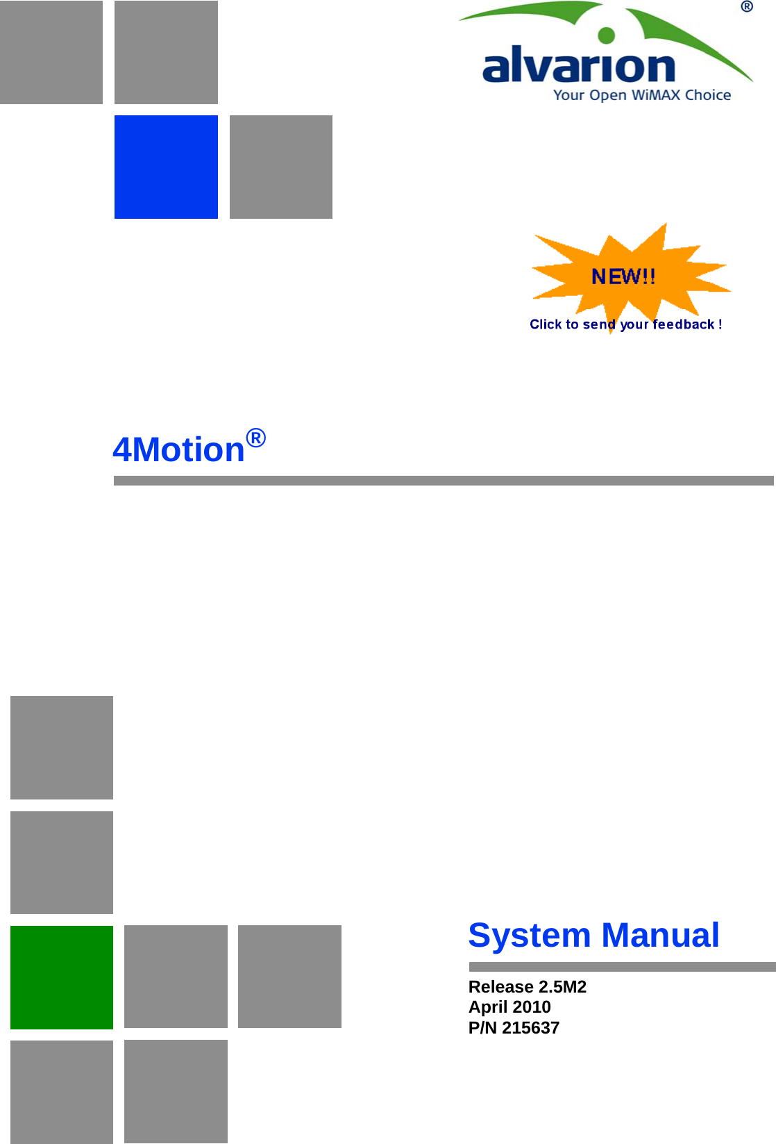
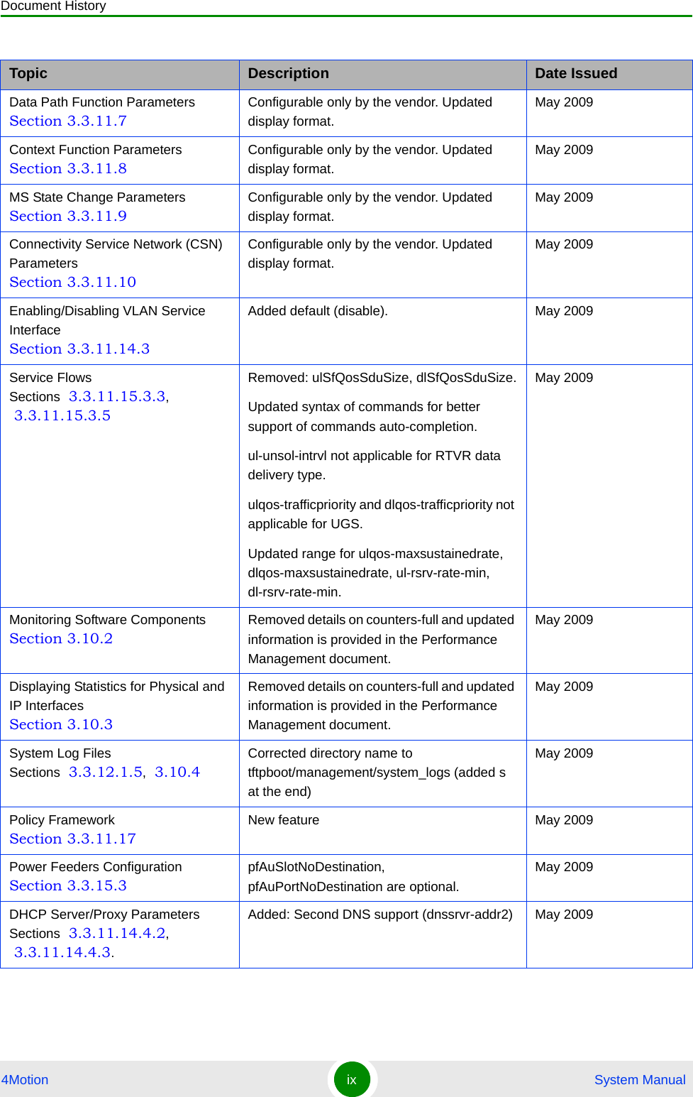
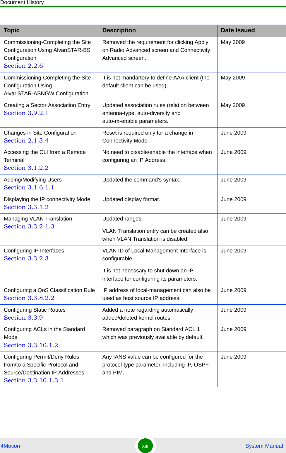
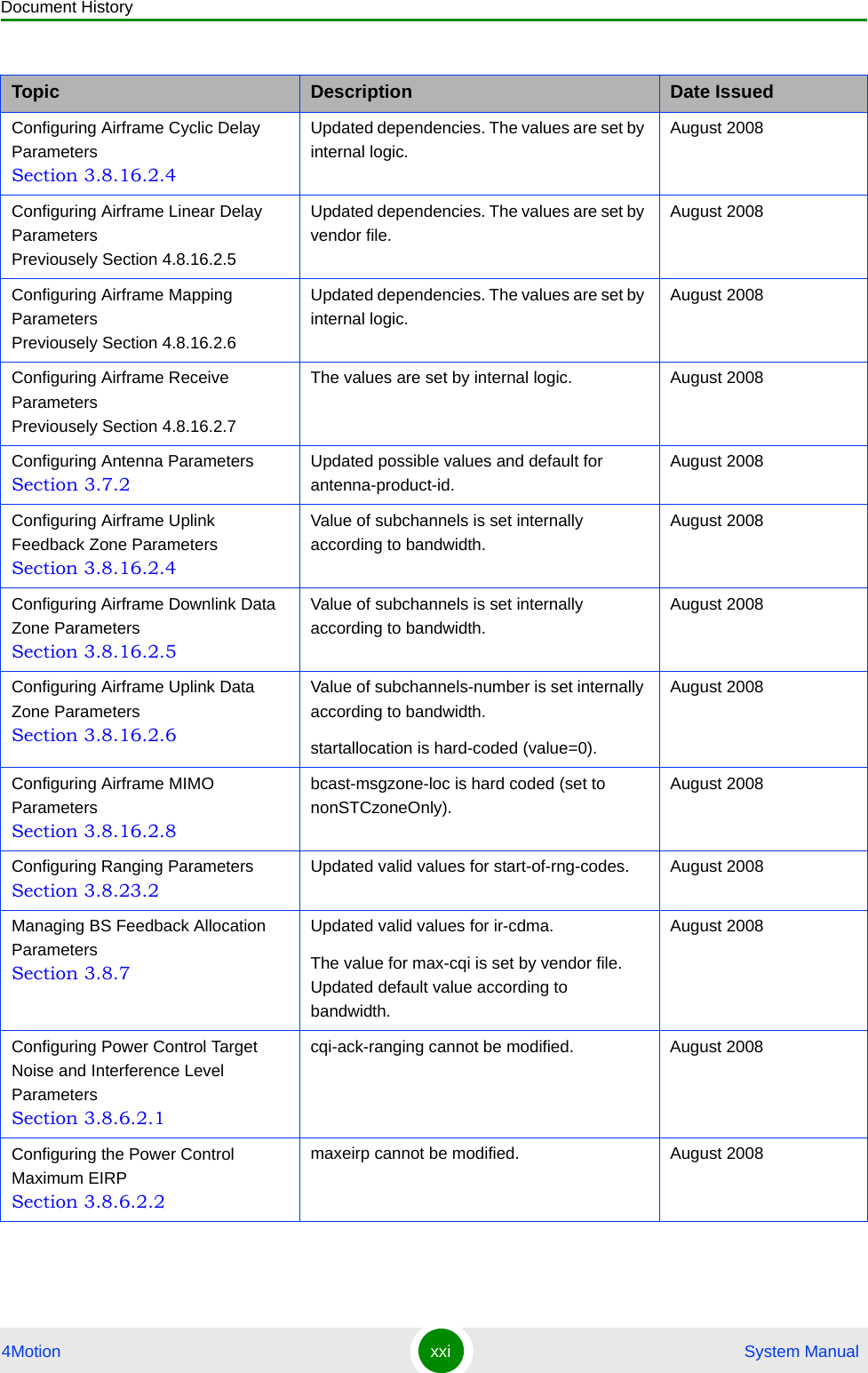
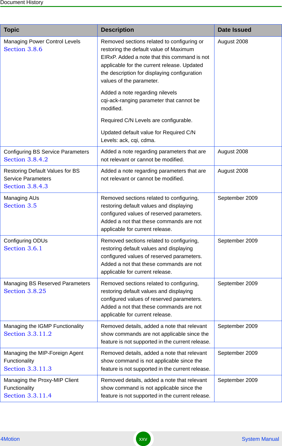
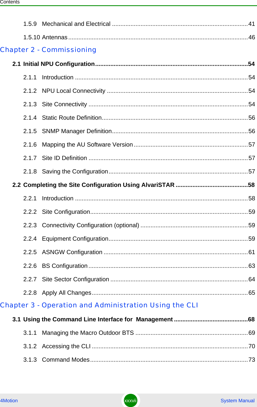
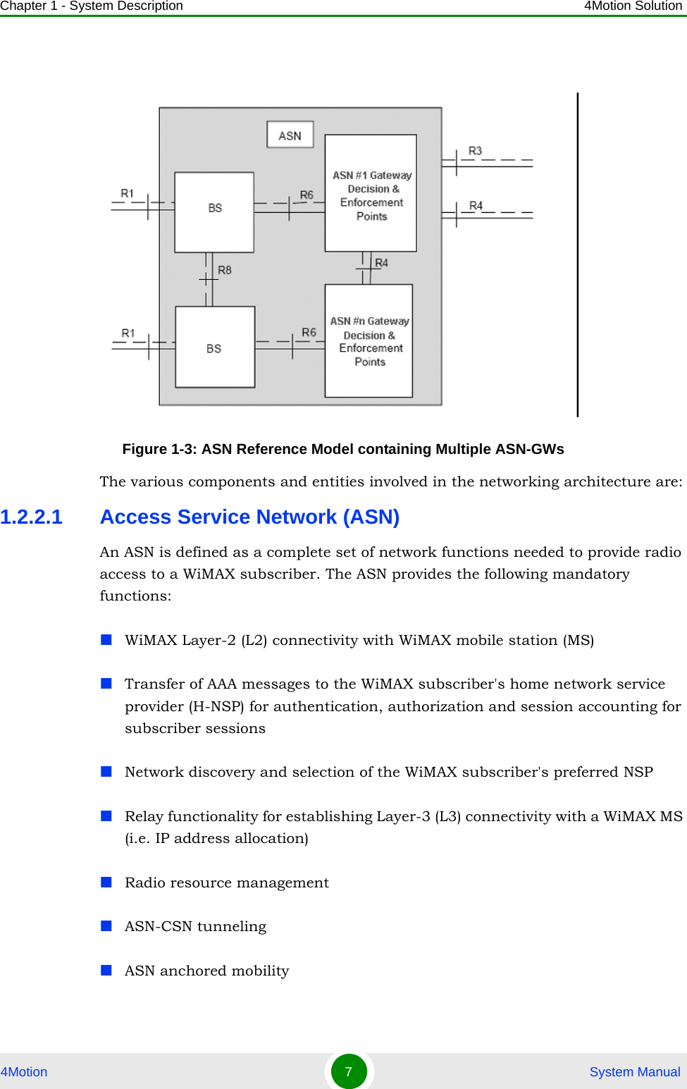
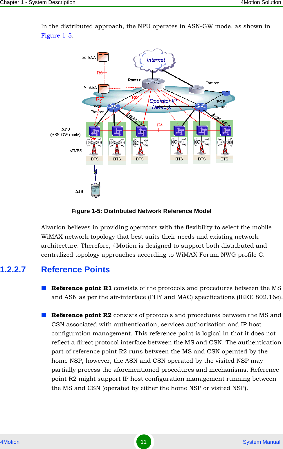
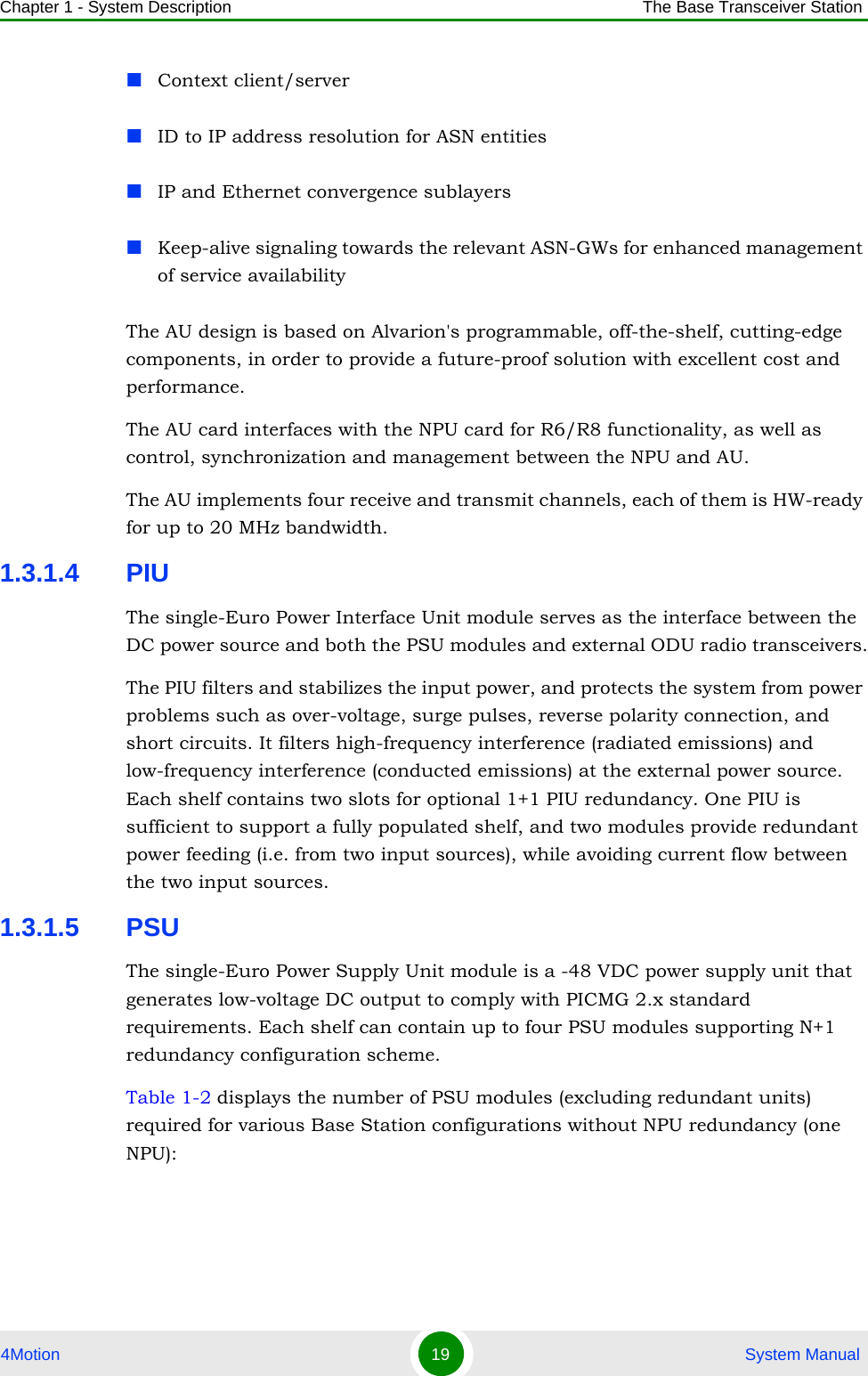
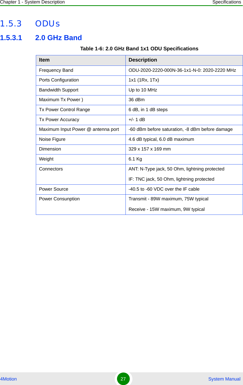
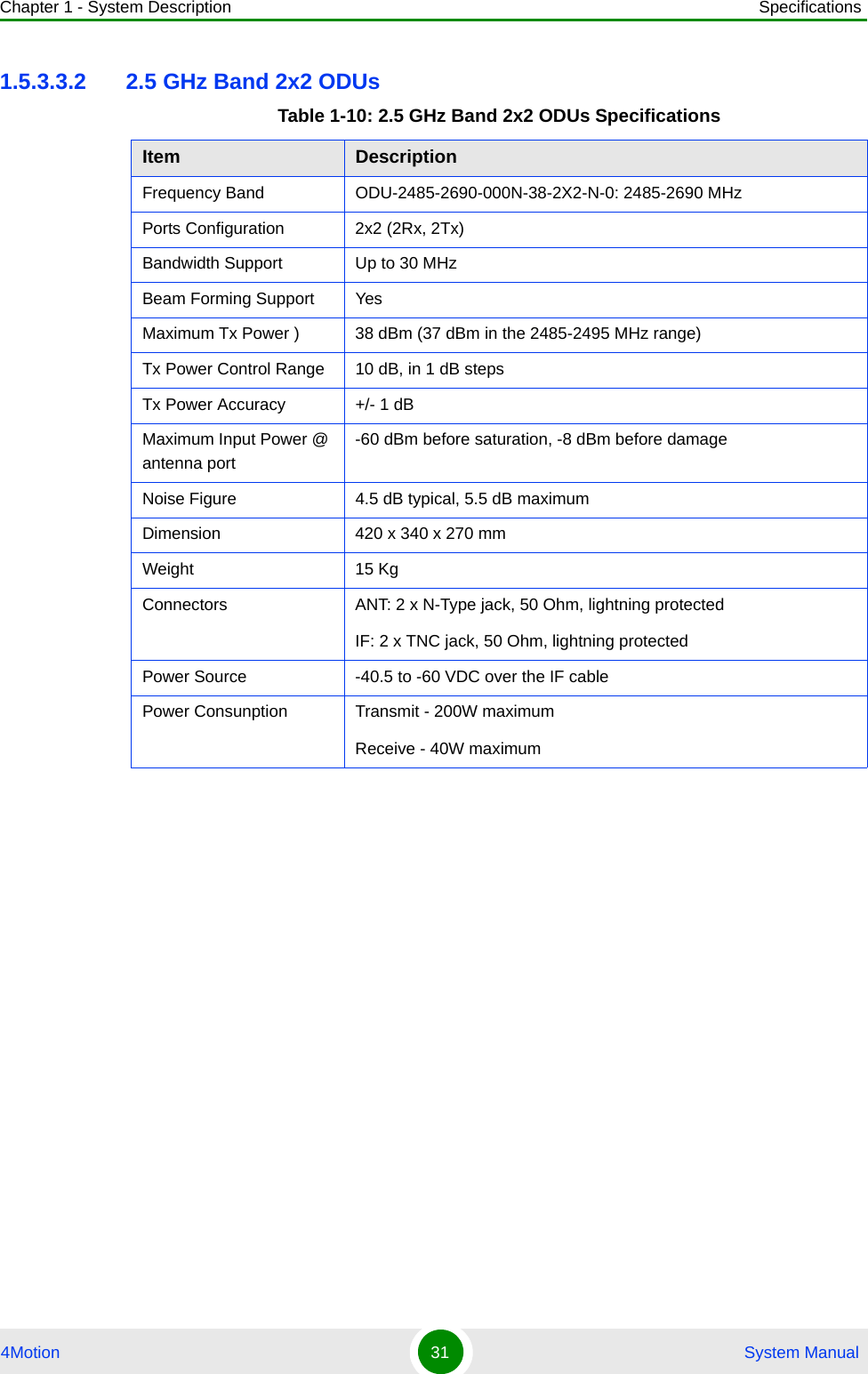
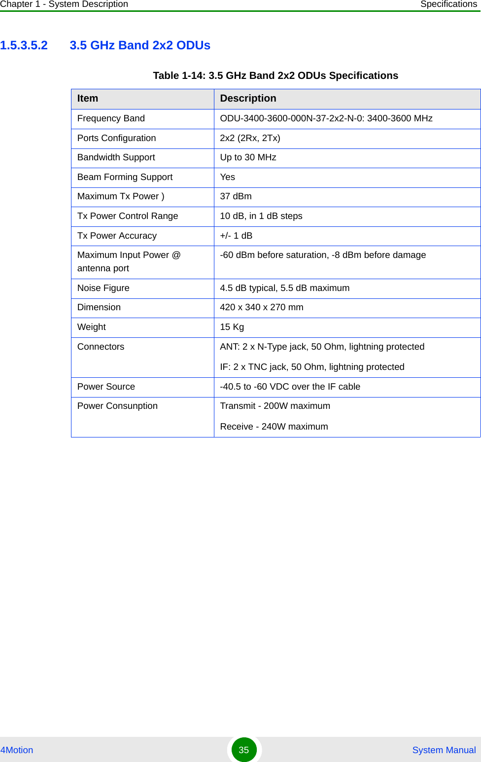
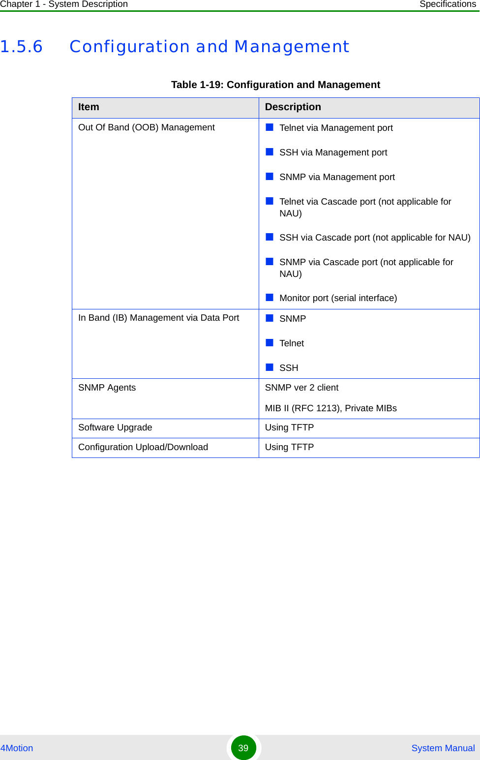
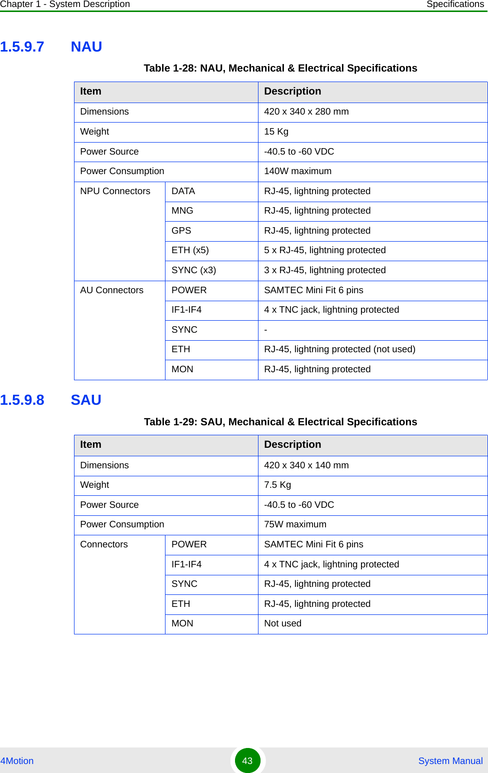
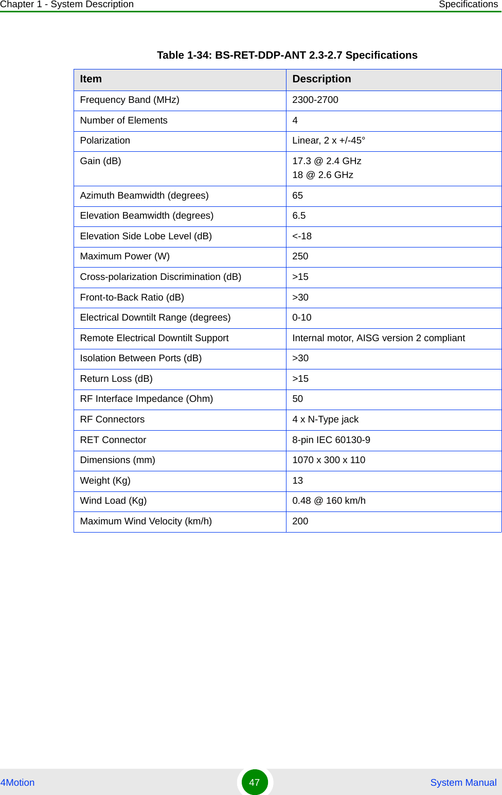


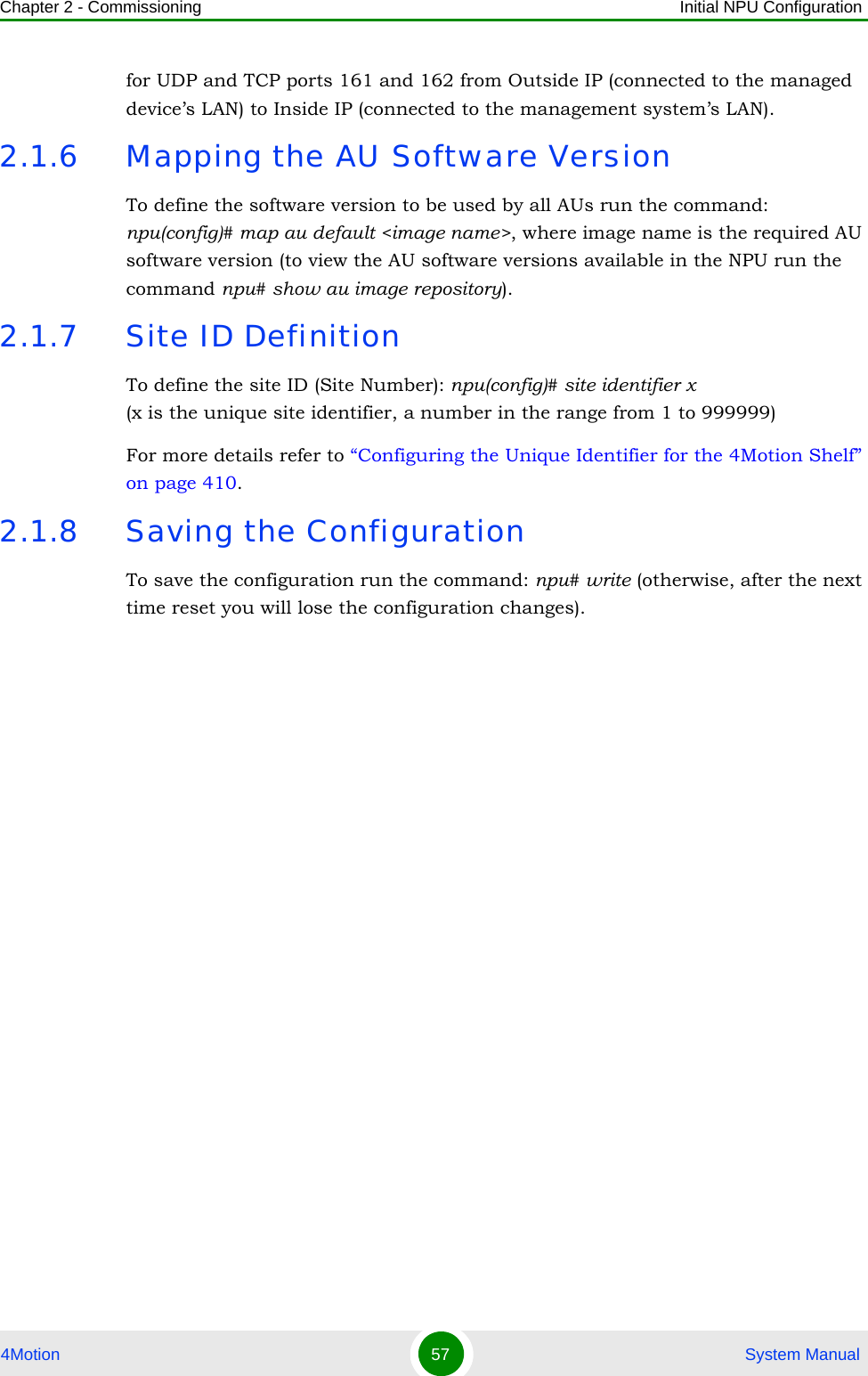
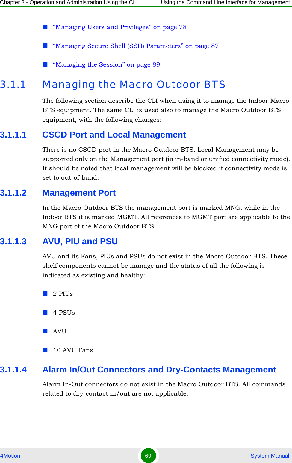
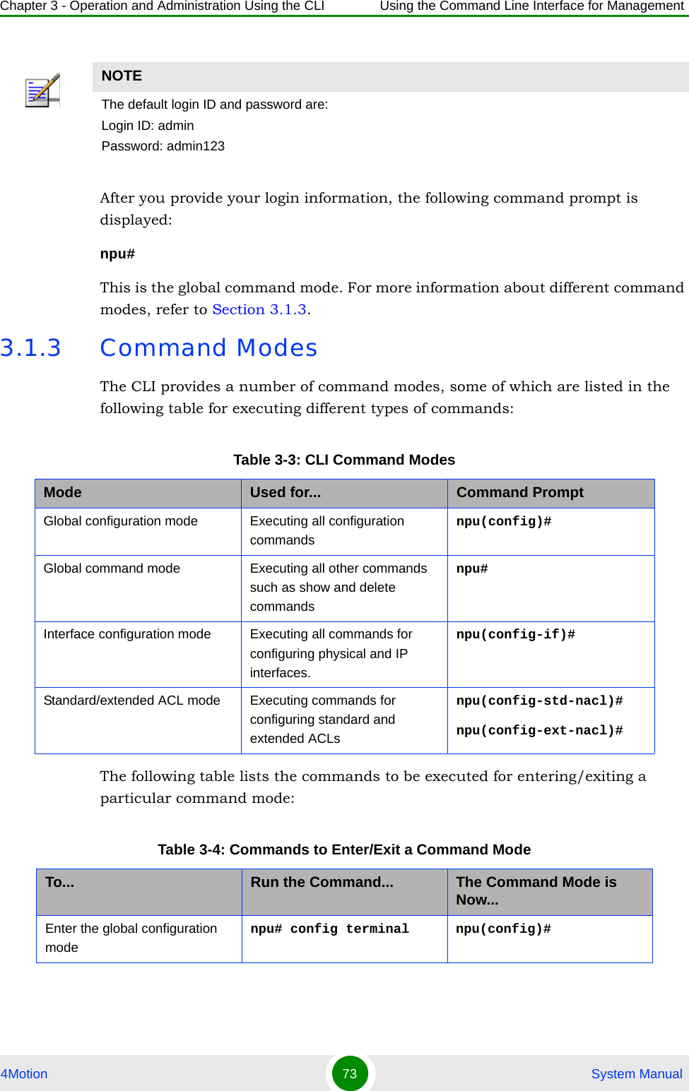
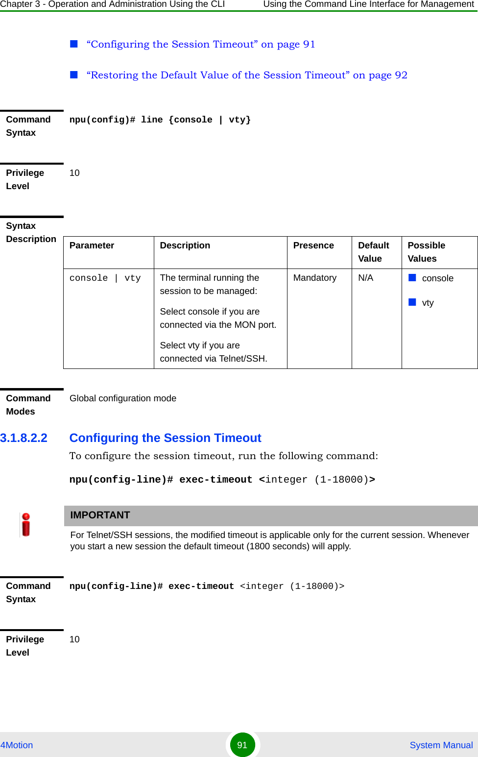
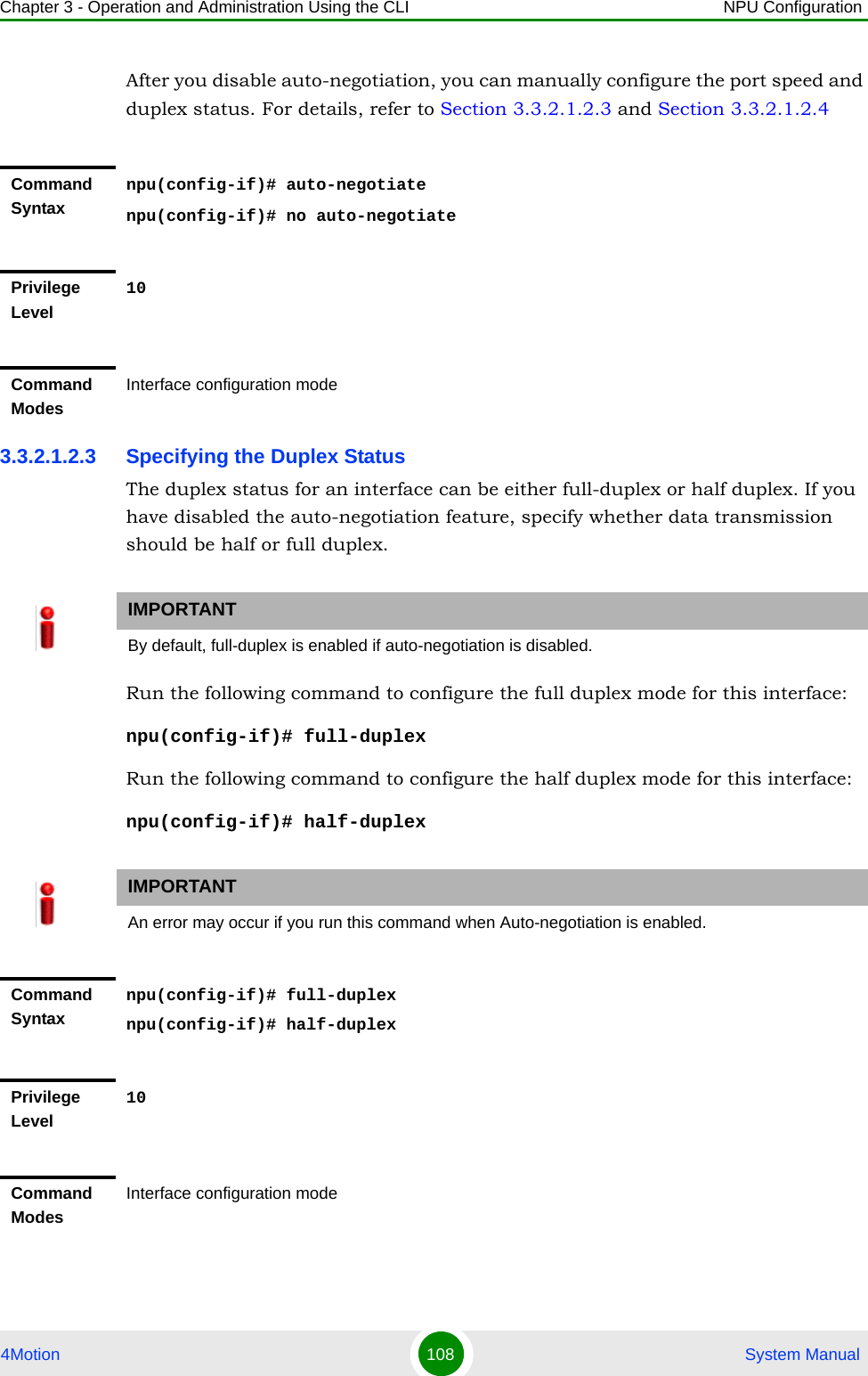
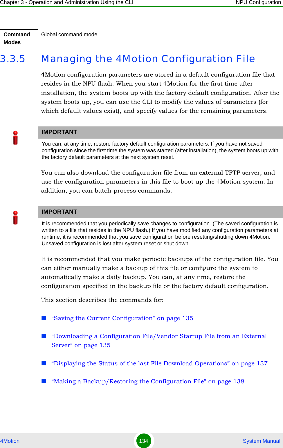
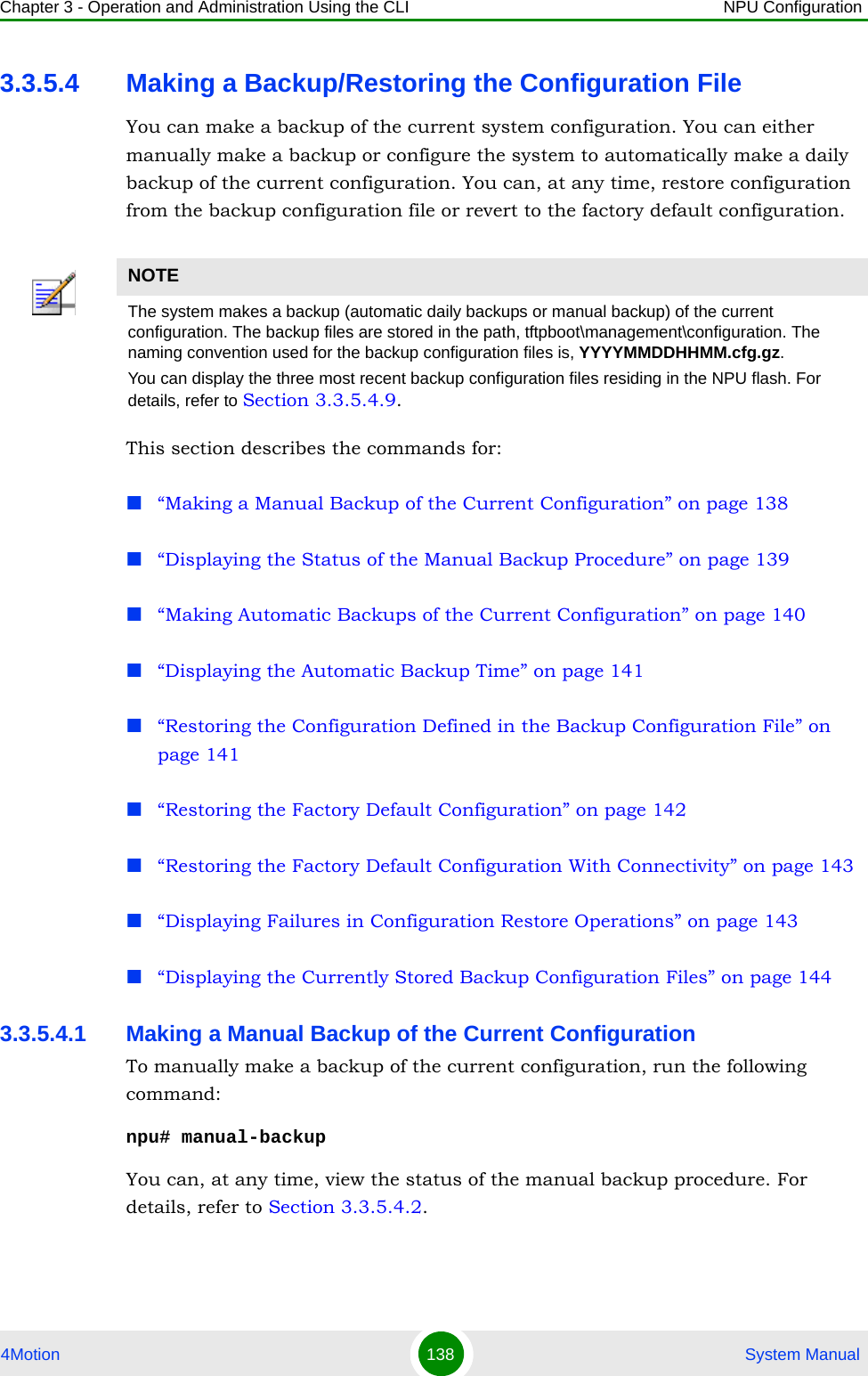
![Chapter 3 - Operation and Administration Using the CLI Using the Command Line Interface for Management4Motion 74 System Manual3.1.4 Interpreting the Command SyntaxThe following table lists the conventions used in the command syntax for all 4Motion commands:Enter the interface configuration modenpu(config)# interface {<interface-type> <interface-id> |internal-mgmt |external-mgmt | bearer | local-mgmt | npu-host | all-au}npu(config-if)# Exit the configuration mode and enter the global command mode.npu(config)# endnpu (config-if)# endnpu#npu#Exit the current configuration mode by one levelnpu (config-if)# exit npu(config)#Table 3-5: Conventions Used in the 4Motion Command SyntaxConvention Description Example{ } Indicates that the parameters enclosed in these brackets are mandatory, and only one of these parameters should be specified.npu(config)# limit { cpu | memory} ([softlimit <limit>] [hardlimit <limit>])This command is used for specifying the soft and hard limits for memory and CPU utilization. The cpu/memory parameters are enclosed within {} brackets, indicating that their presence is mandatory, and that only one of these parameters is required. ( ) Indicates that one or all parameters enclosed within these brackets are optional. However, the presence of at least one parameter is required to successfully execute this command.npu(config)# limit { cpu | memory} ([softlimit <limit>] [hardlimit <limit>])This command is used for specifying the soft and hard limits for memory and CPU utilization. The softlimit and hardlimit parameters are enclosed within () brackets, indicating that you are required to specify the value of at least one of these parameters to successfully execute this command.Table 3-4: Commands to Enter/Exit a Command Mode](https://usermanual.wiki/Alvarion-Technologies/BMAX-2-OR-25/User-Guide-1325752-Page-116.png)
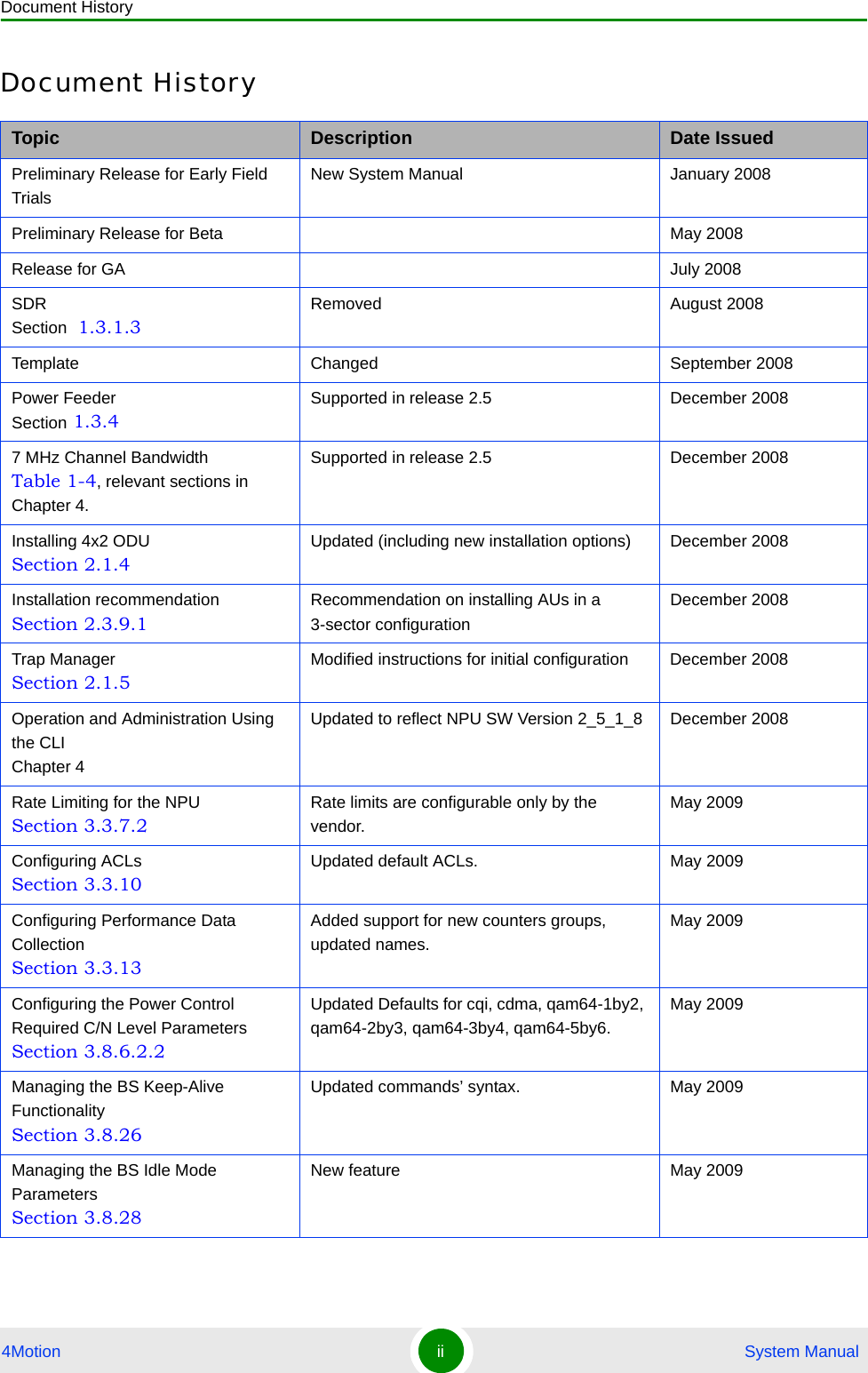
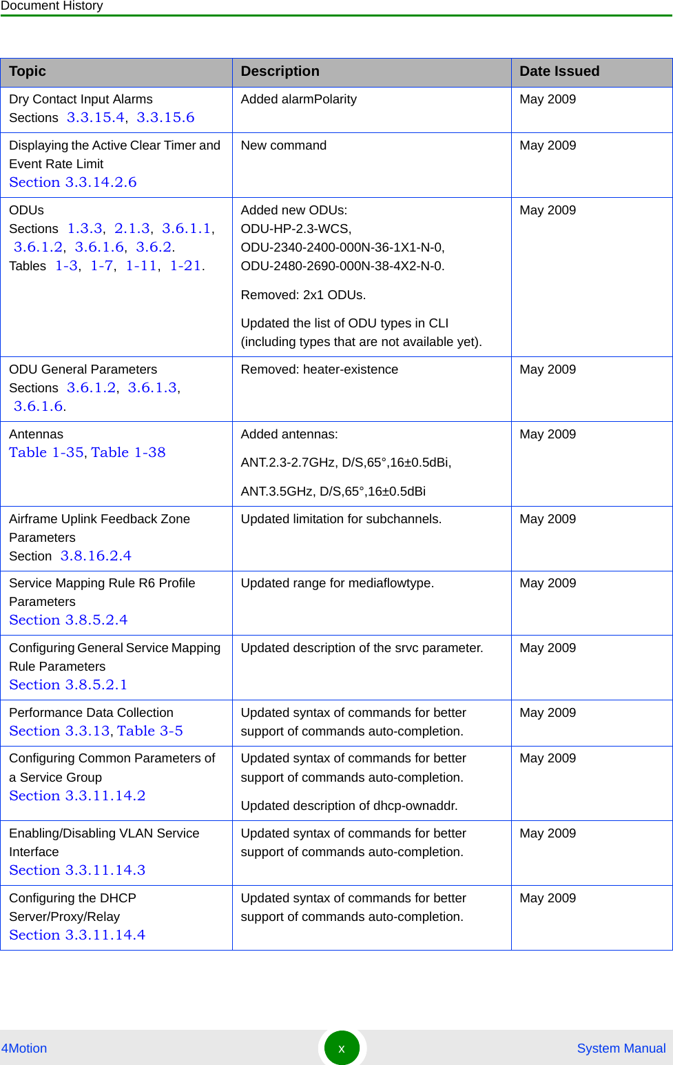
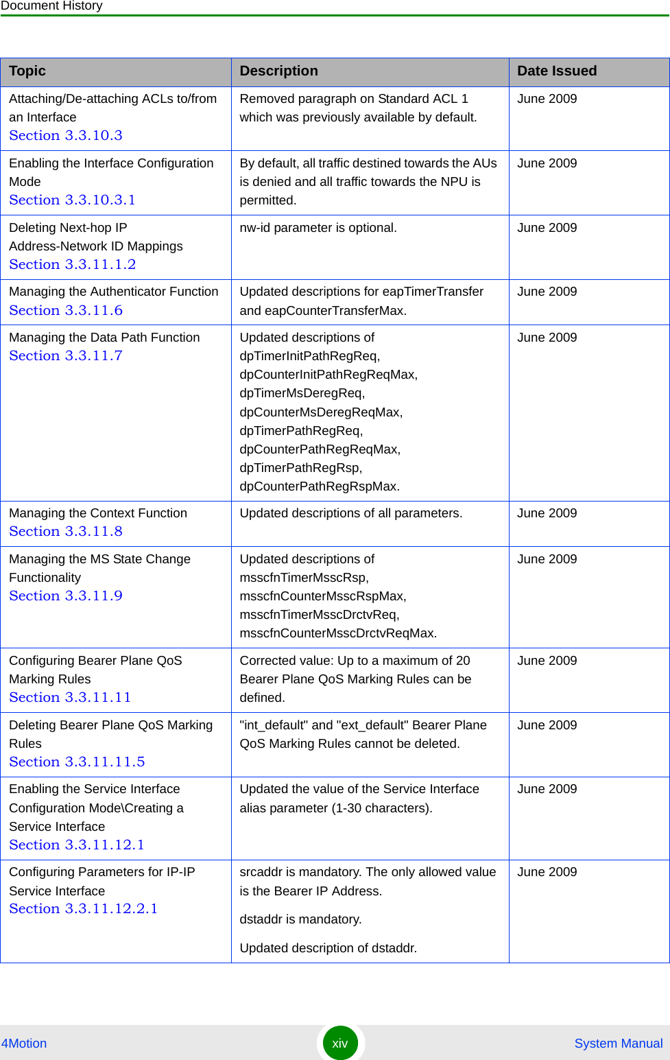
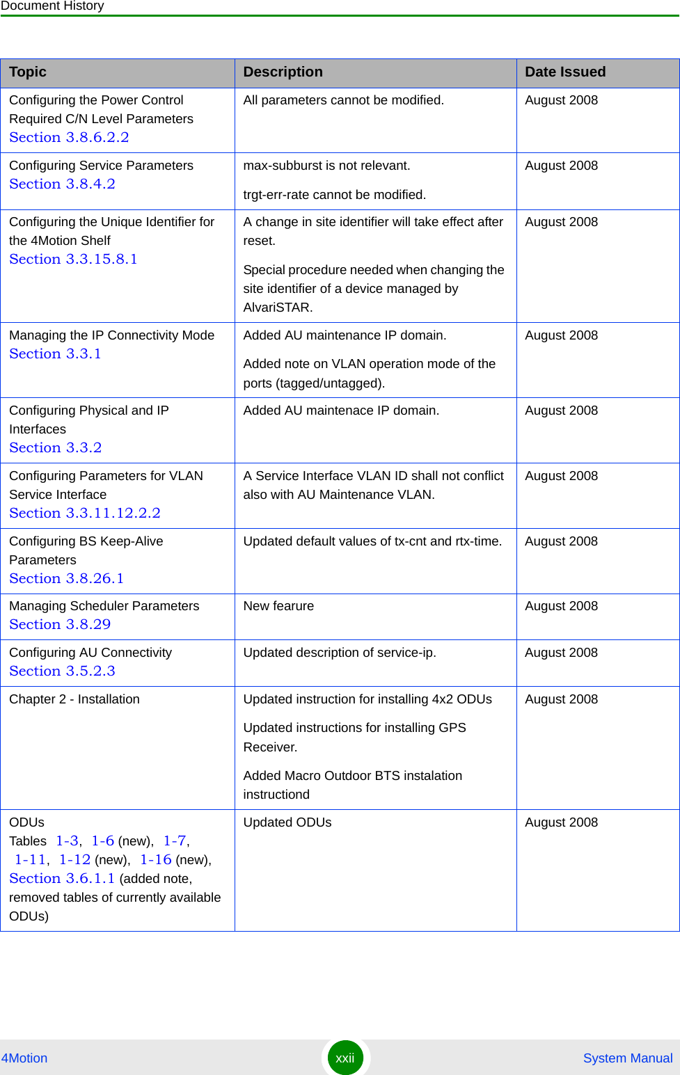
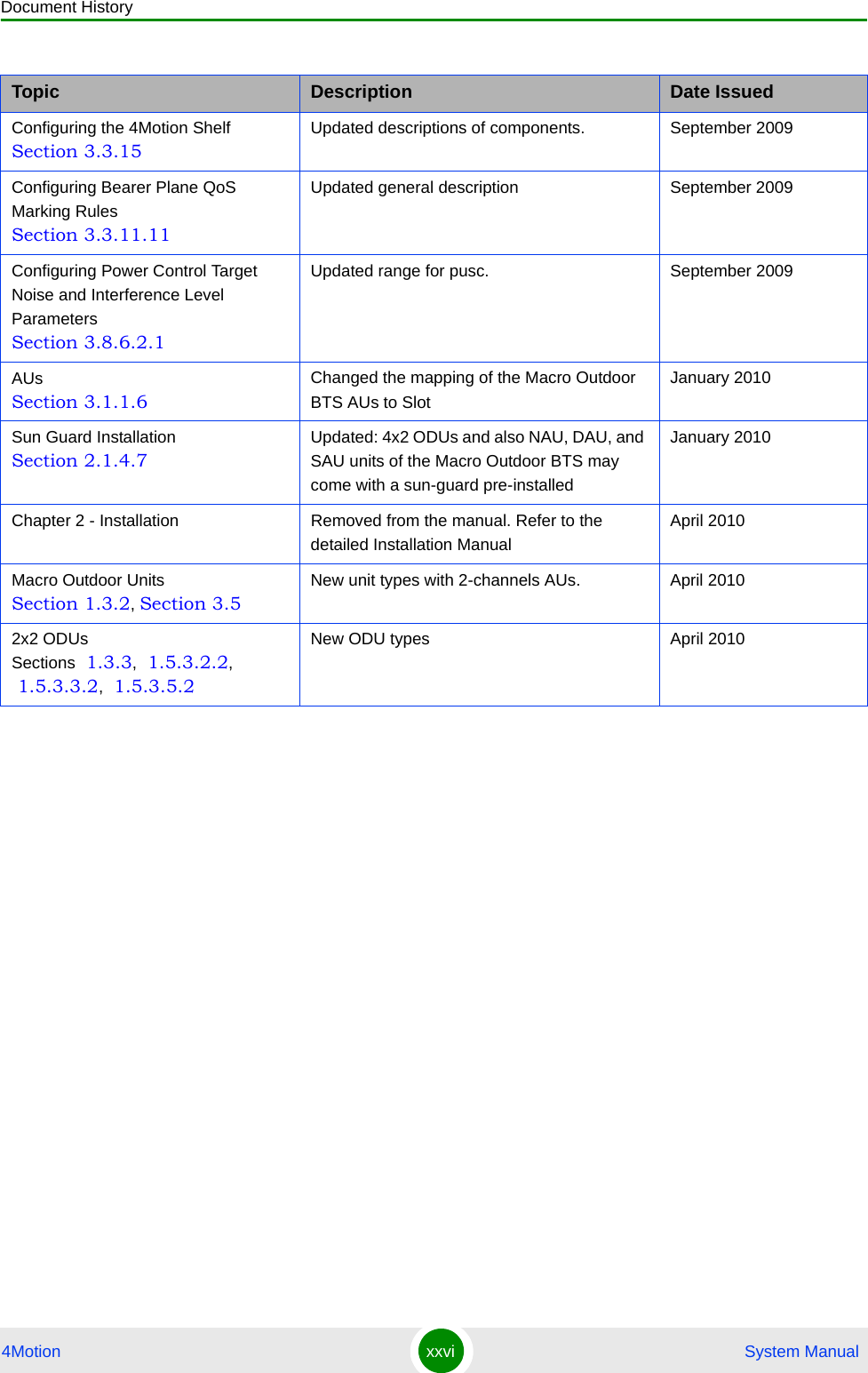
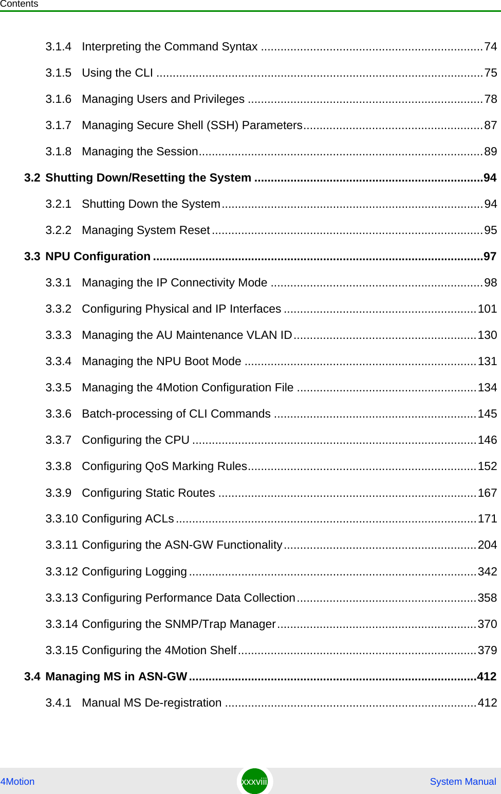
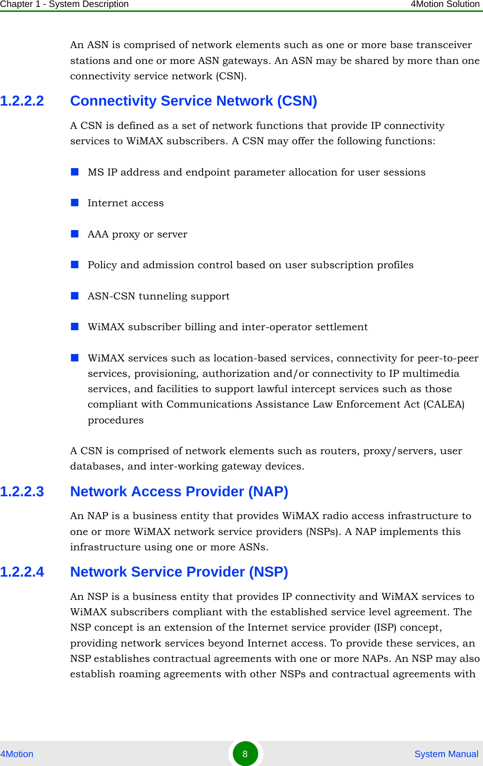
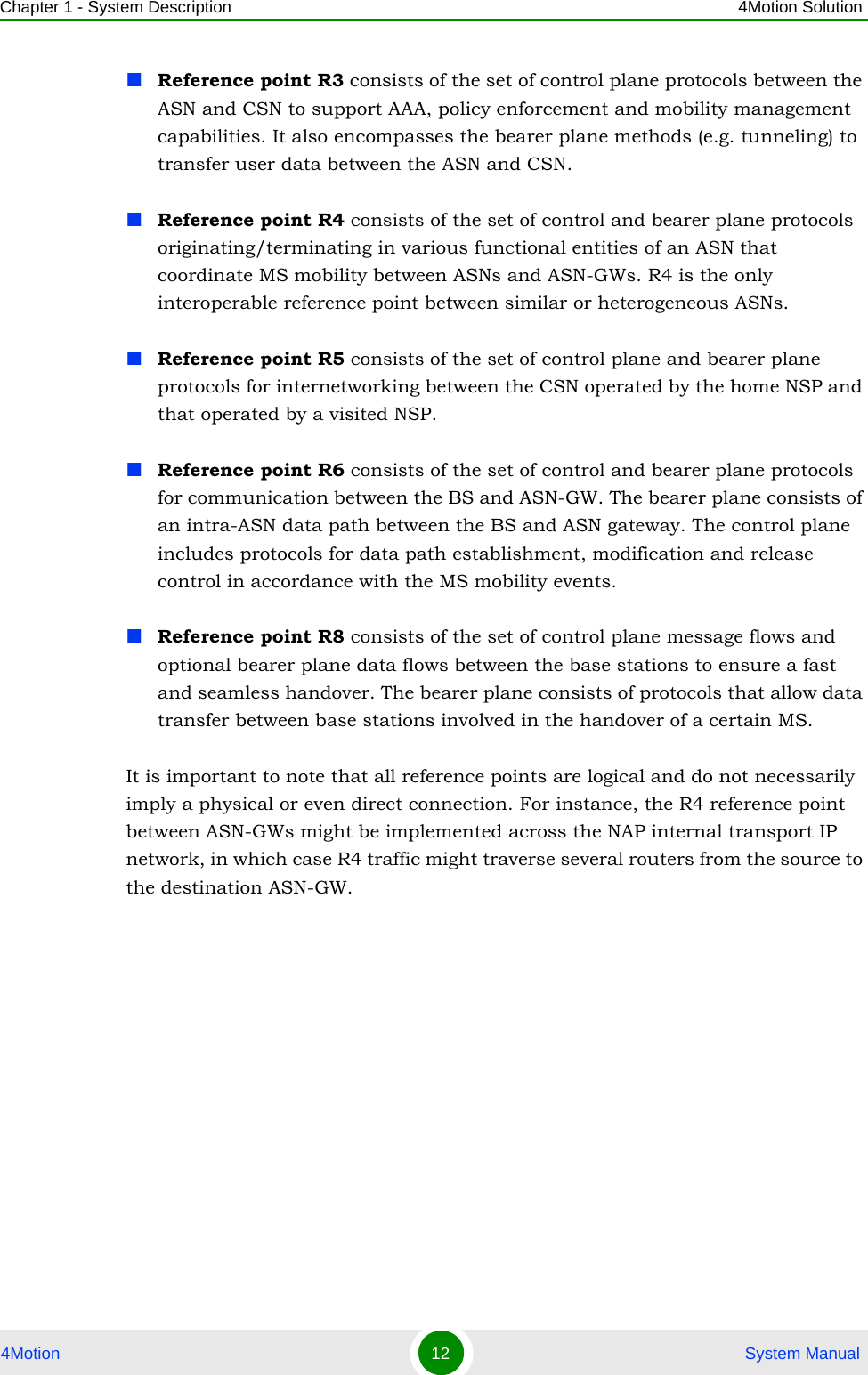
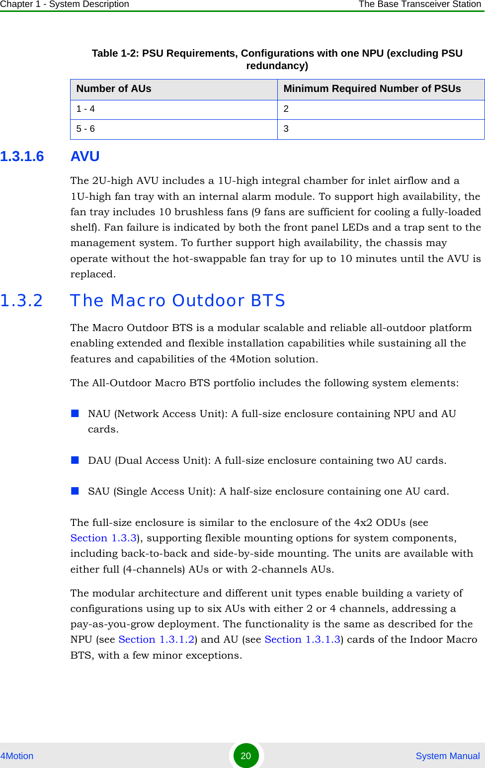
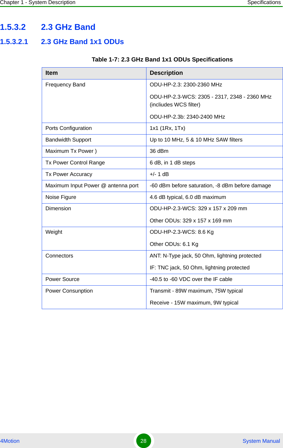
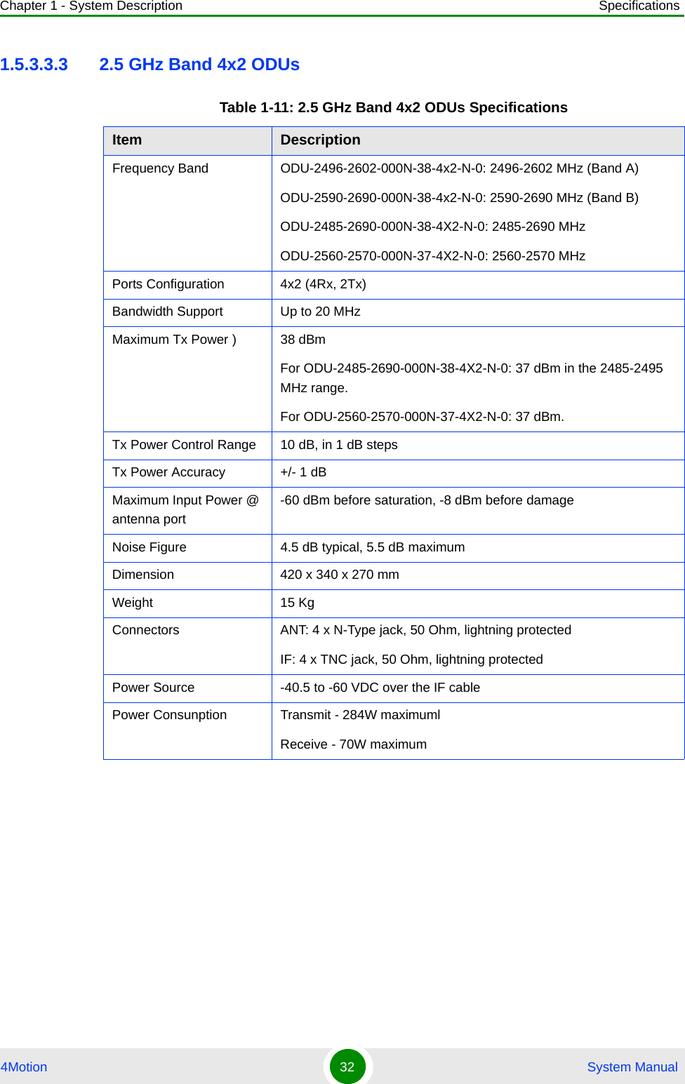
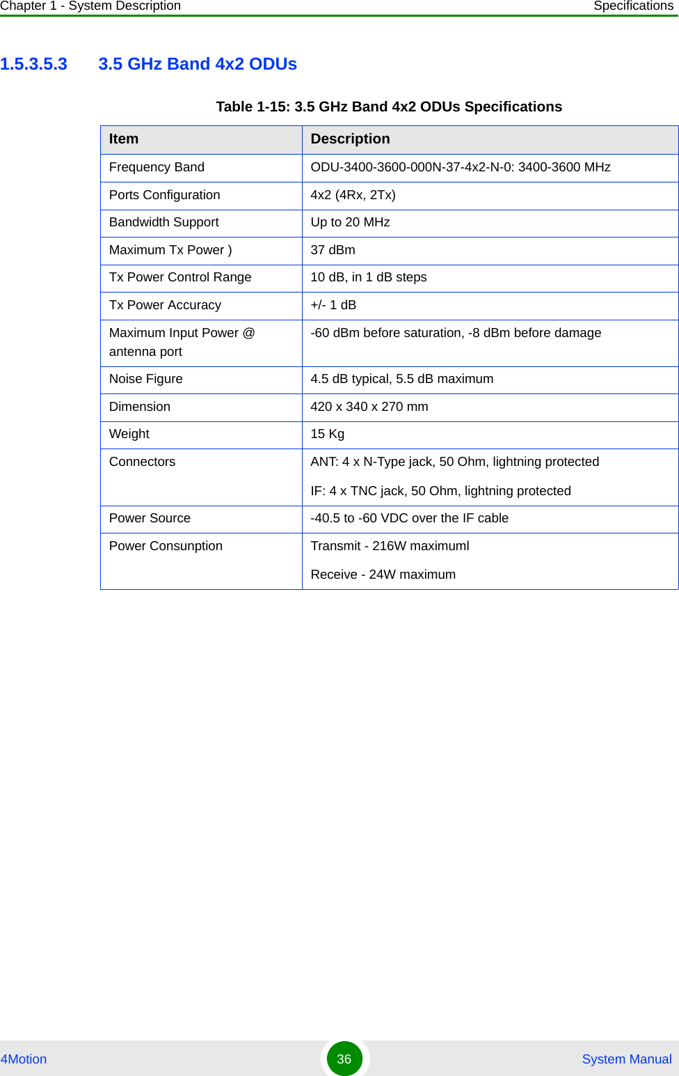
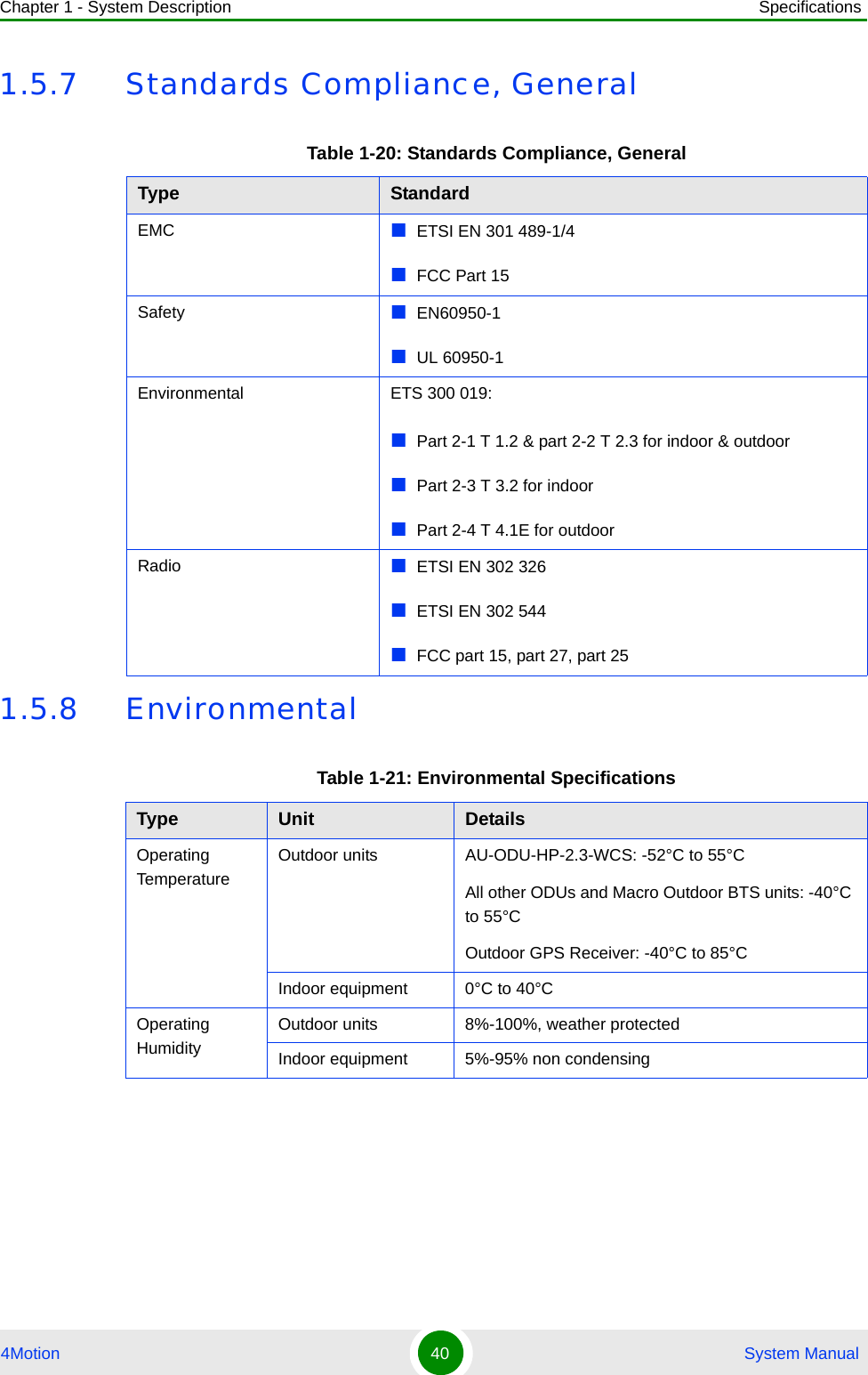
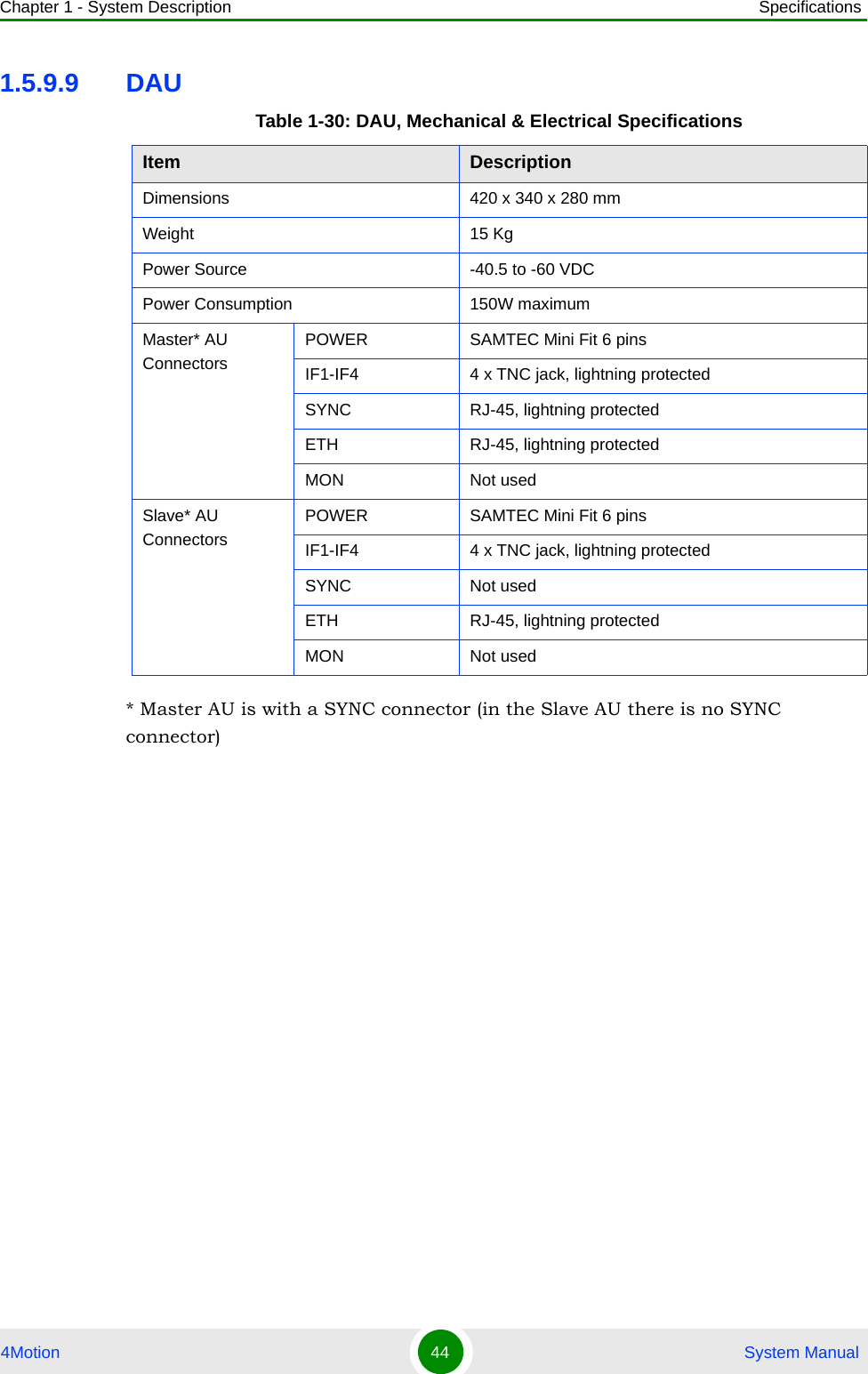
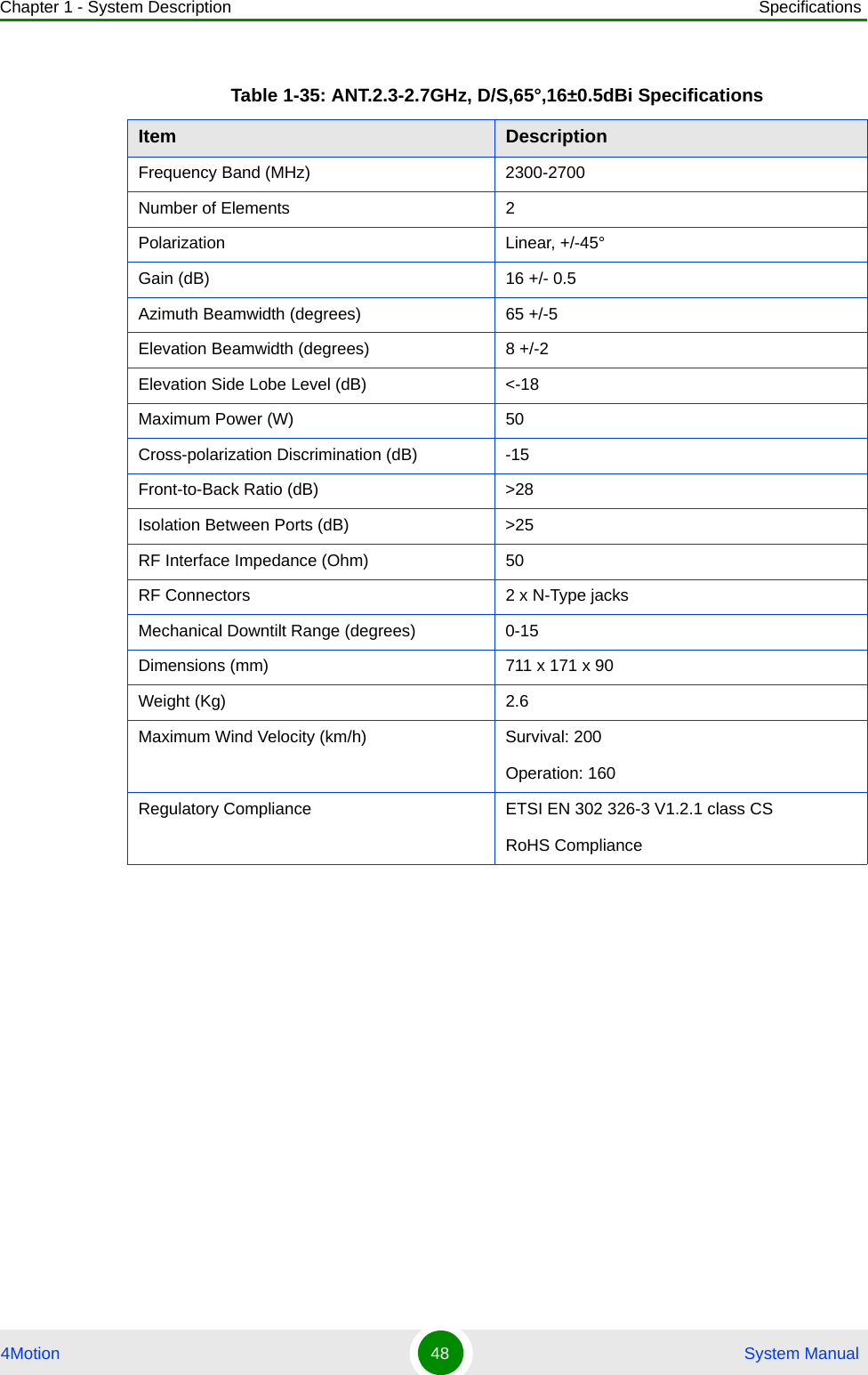
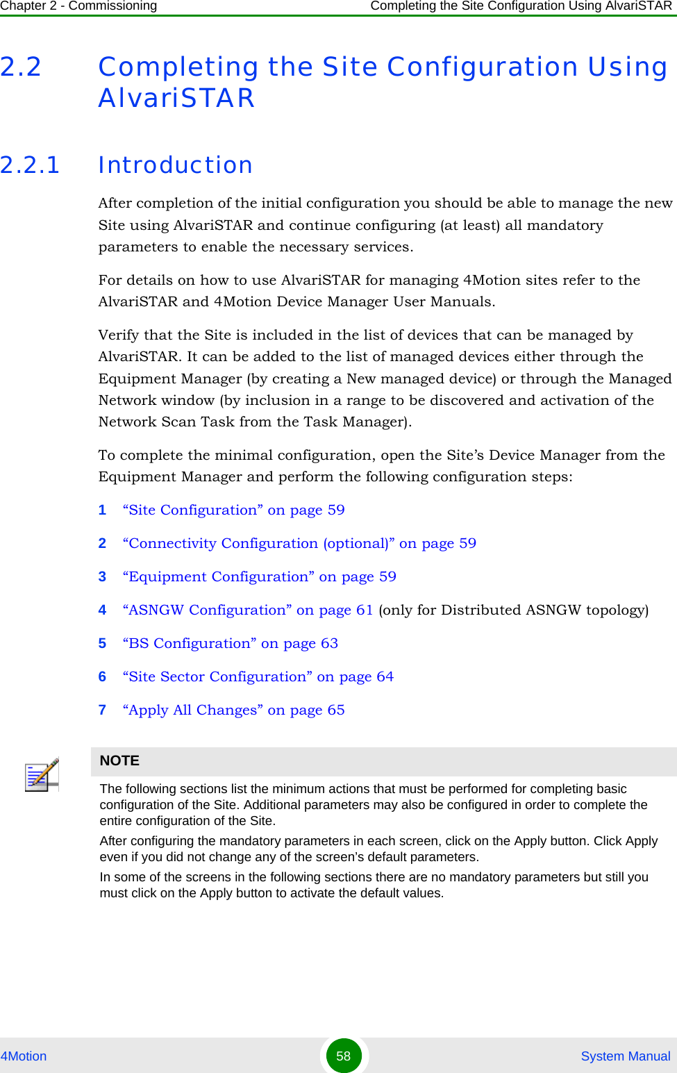
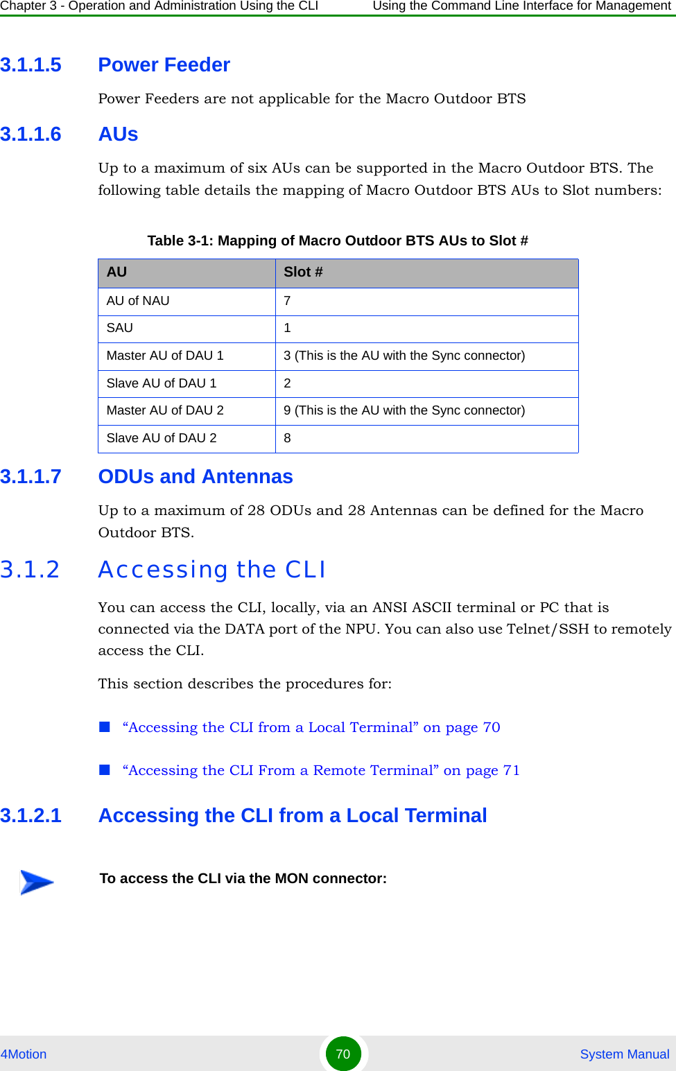
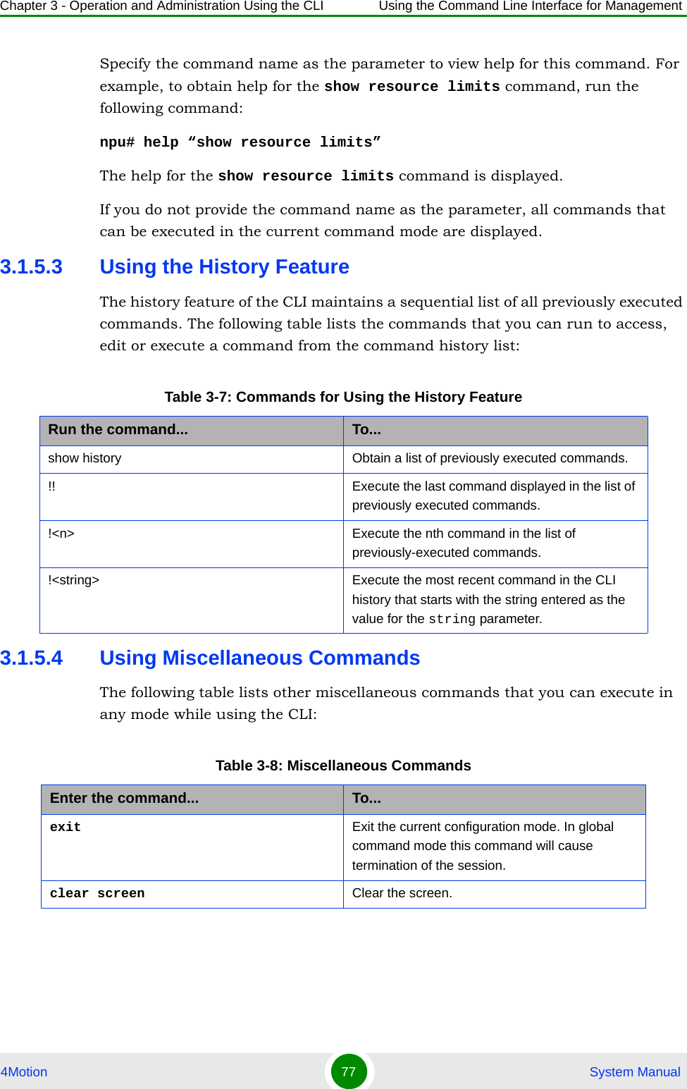
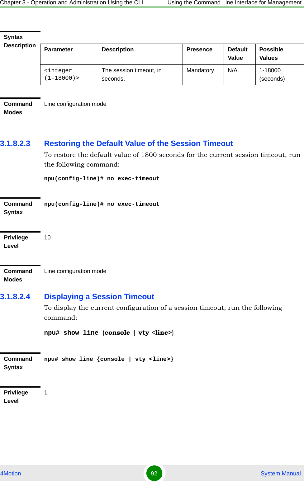
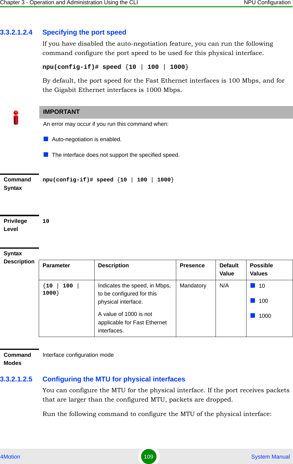
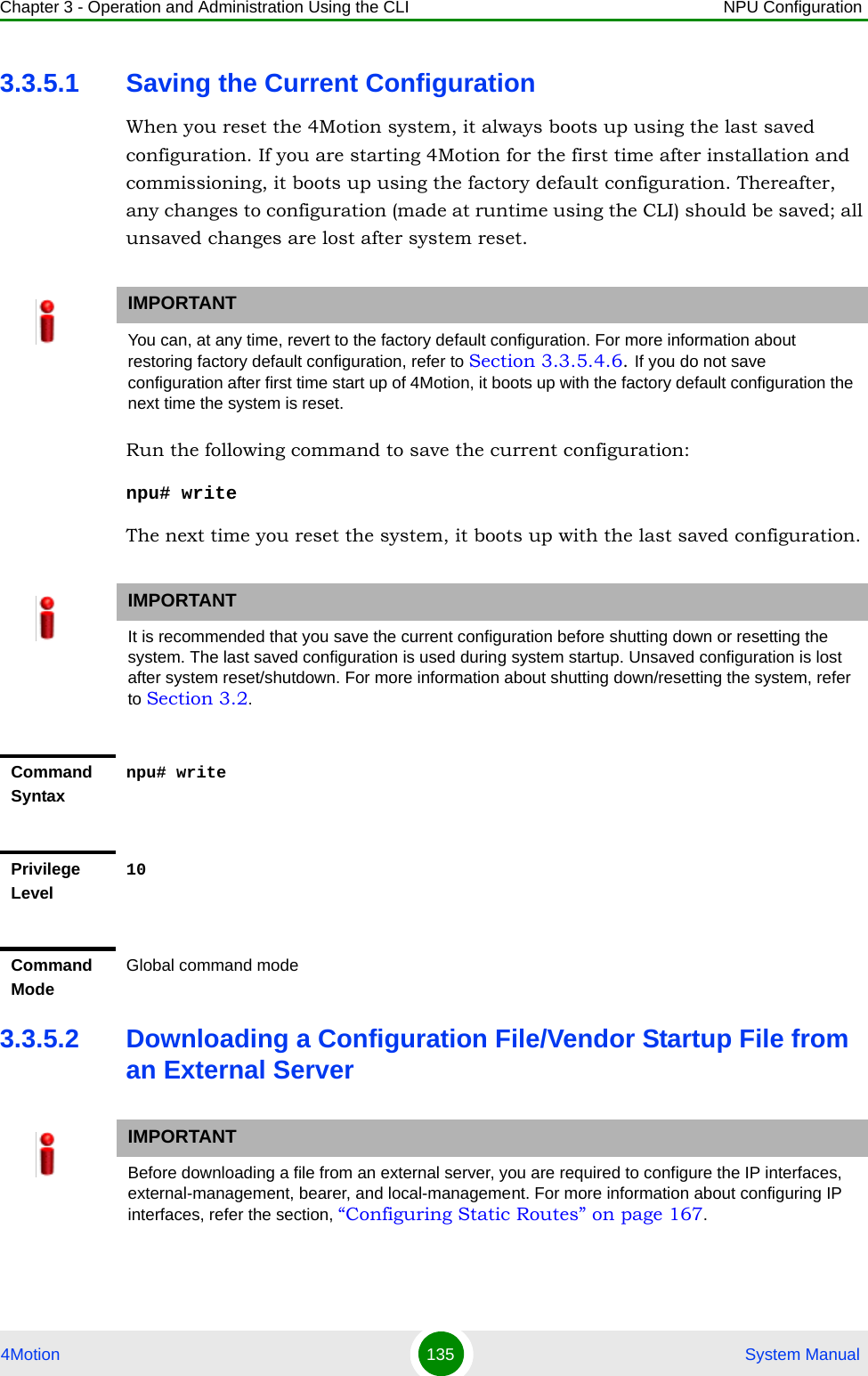
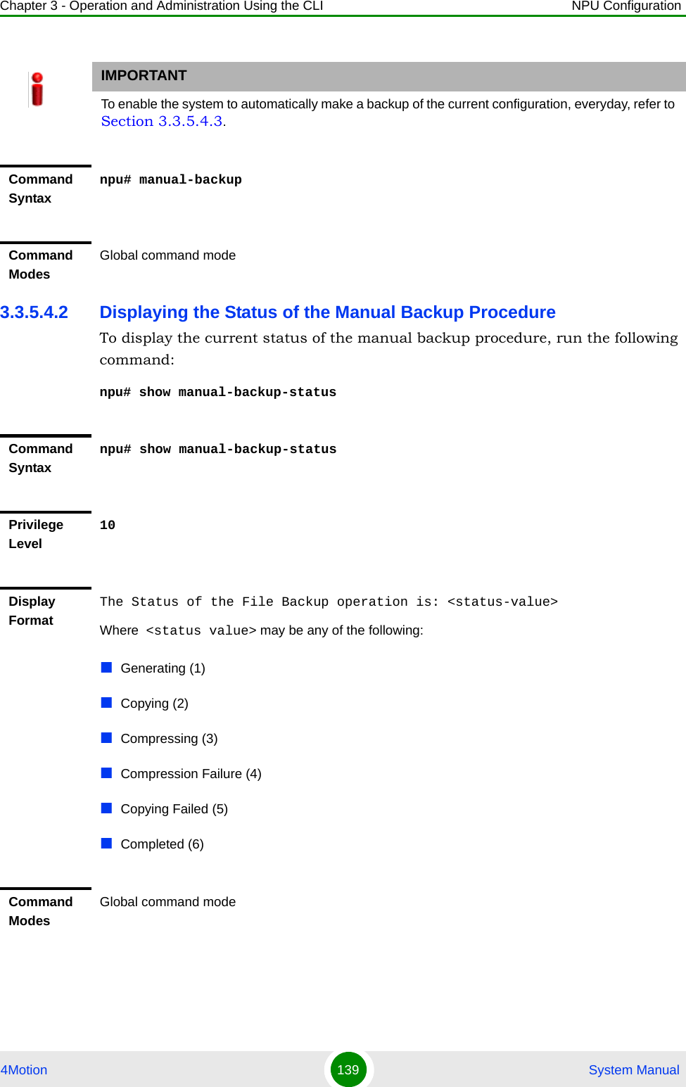
![Chapter 3 - Operation and Administration Using the CLI Using the Command Line Interface for Management4Motion 75 System Manual3.1.5 Using the CLITo help you use the CLI, this section provides information about:“Using Control Characters” on page 76[ ] Indicates that the parameter enclosed within these brackets is optional.npu(config)# reboot from shadow [<shadow image name>]This command is used to reboot the system with the shadow image. The shadow image name parameter is enclosed with the [ ] brackets, indicating that it is optional. If you do not specify the value of this parameter, the system automatically boots up with the last downloaded shadow image.< > Indicates that the parameter is mandatory and requires a user-defined value (and not a discrete value).npu(config)# load to shadow <shadow image name>This command is used to load the system with a particular shadow image. It is mandatory to specify a value for the shadow image name parameter; otherwise an error is raised by the system. The value of this parameter is not a discrete value; you are required to specify a value for this parameter.| Indicates the OR conditional operator that is used between two or more parameters. The presence of this parameter indicates that only one of the parameters separated by the I conditional parameter should be specified in the command.npu(config)# pm-group enable npu {BckhlPort | MgmtPort | CascPort | AuPortTable | IntMgmtIf | ExtMgmtIf | LclMgmtIf | BearerIf | Sfa | DatapathFn | AaaClient | Authenticator | ContextFn | ProxyDhcp | RelayDhcp | ServerDhcp | MsStateChangeFn}This command is used to specify the group for which performance data collection and storage is to be enabled. The | conditional operator indicates that only one parameter should be specified.NOTEIn this document, all discrete values are specified in boldface, and all user-defined values are not bold.Table 3-5: Conventions Used in the 4Motion Command Syntax](https://usermanual.wiki/Alvarion-Technologies/BMAX-2-OR-25/User-Guide-1325752-Page-117.png)
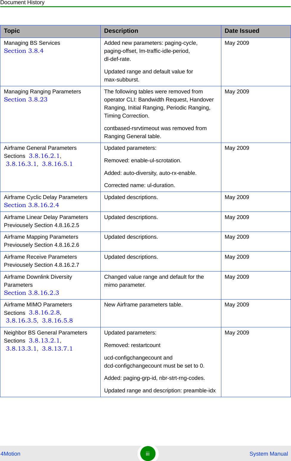
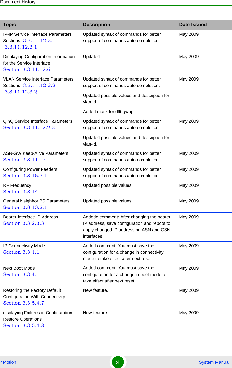
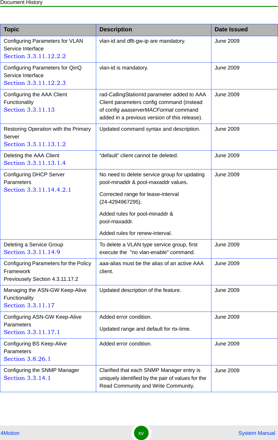
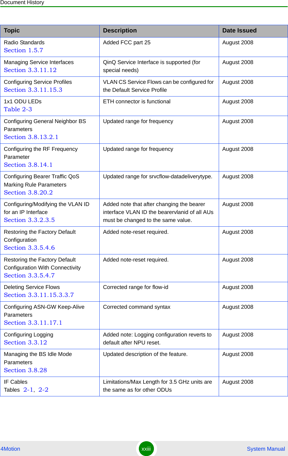
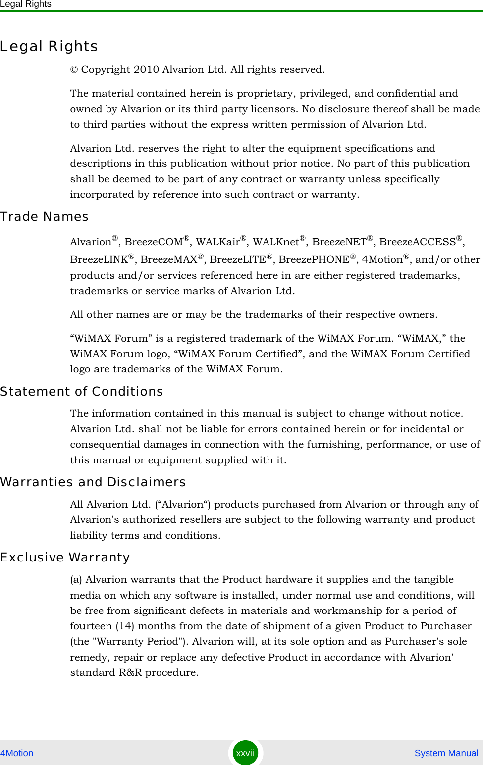
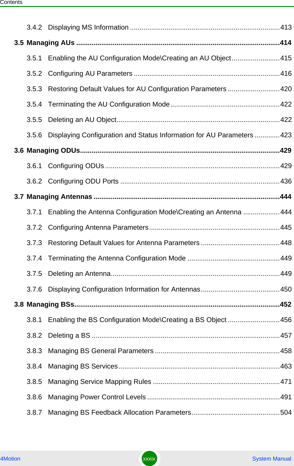
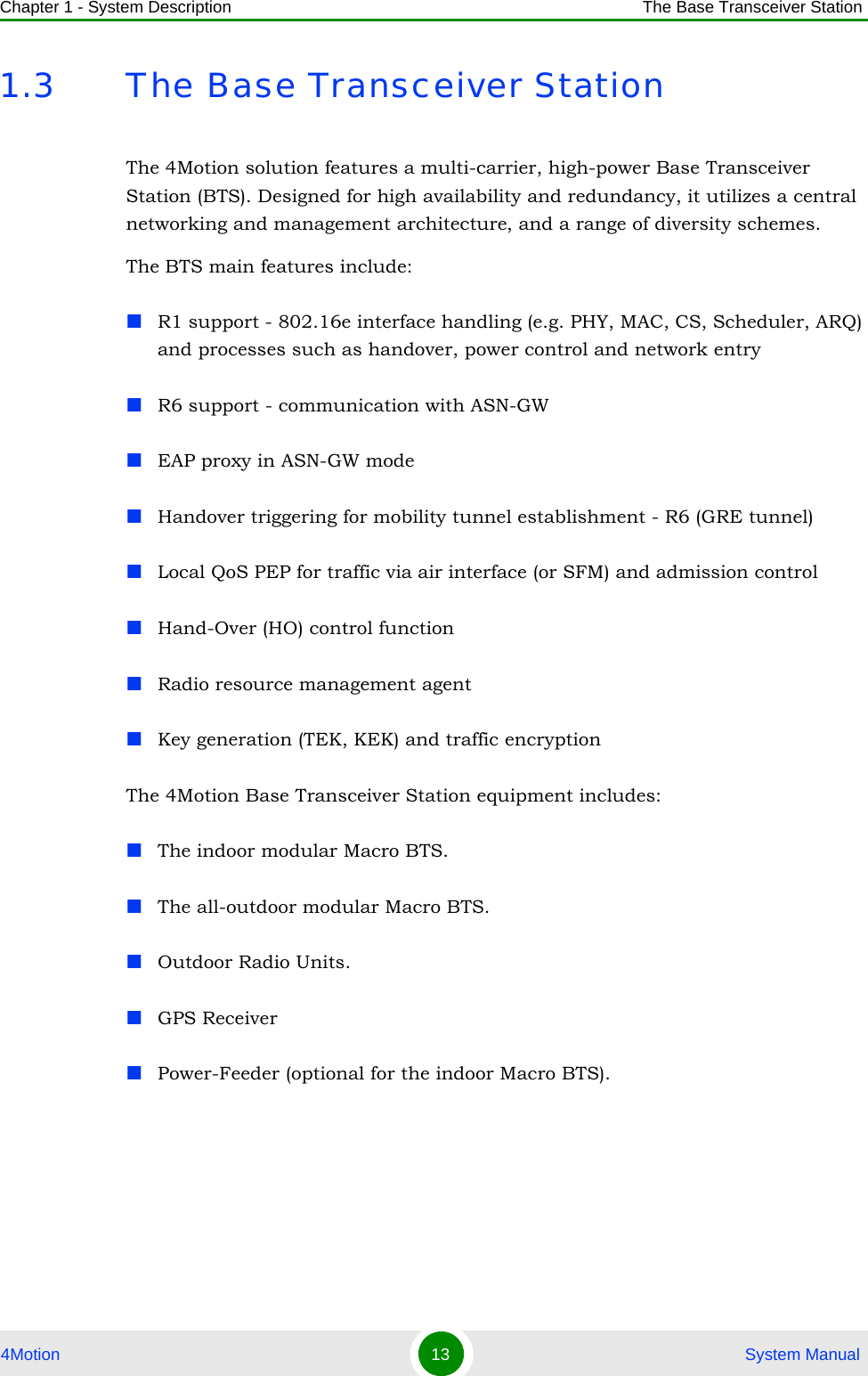
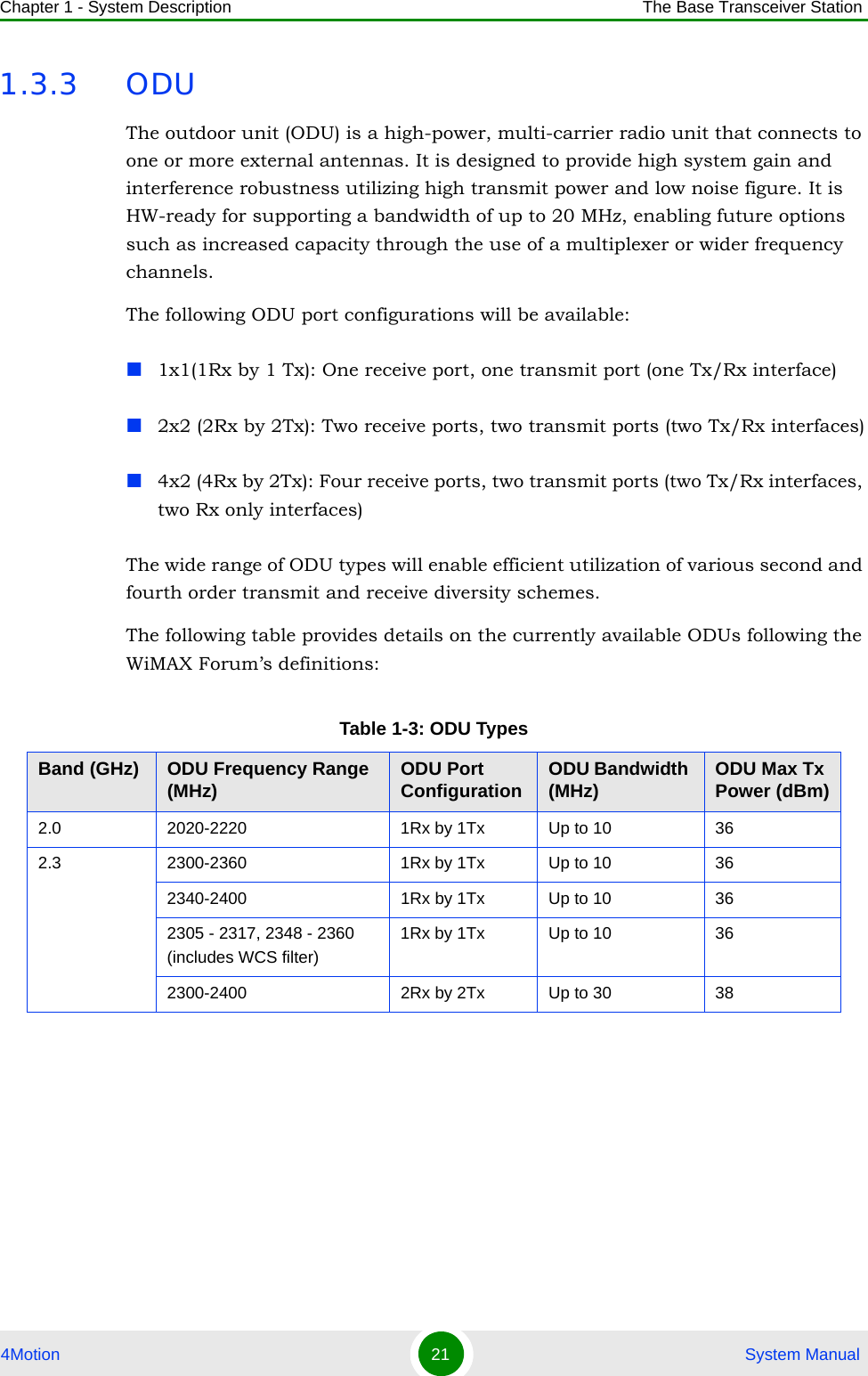
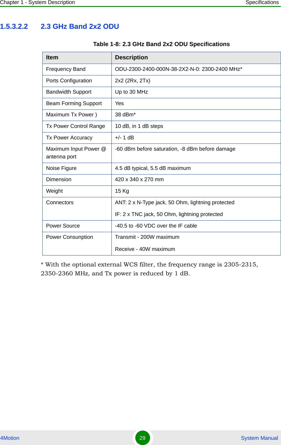
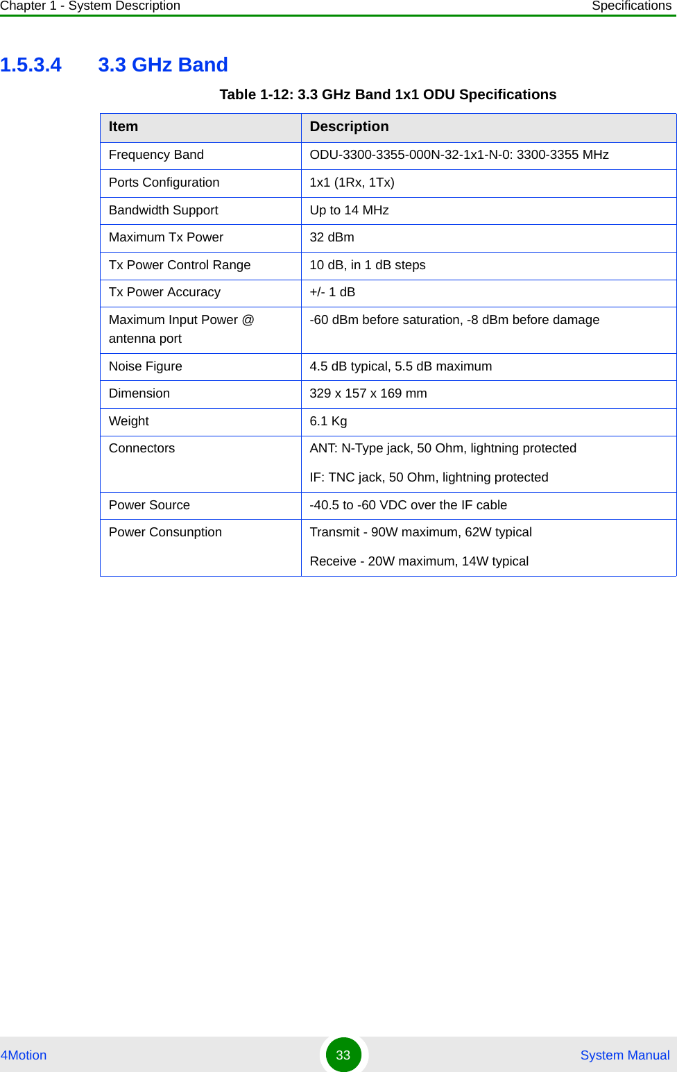
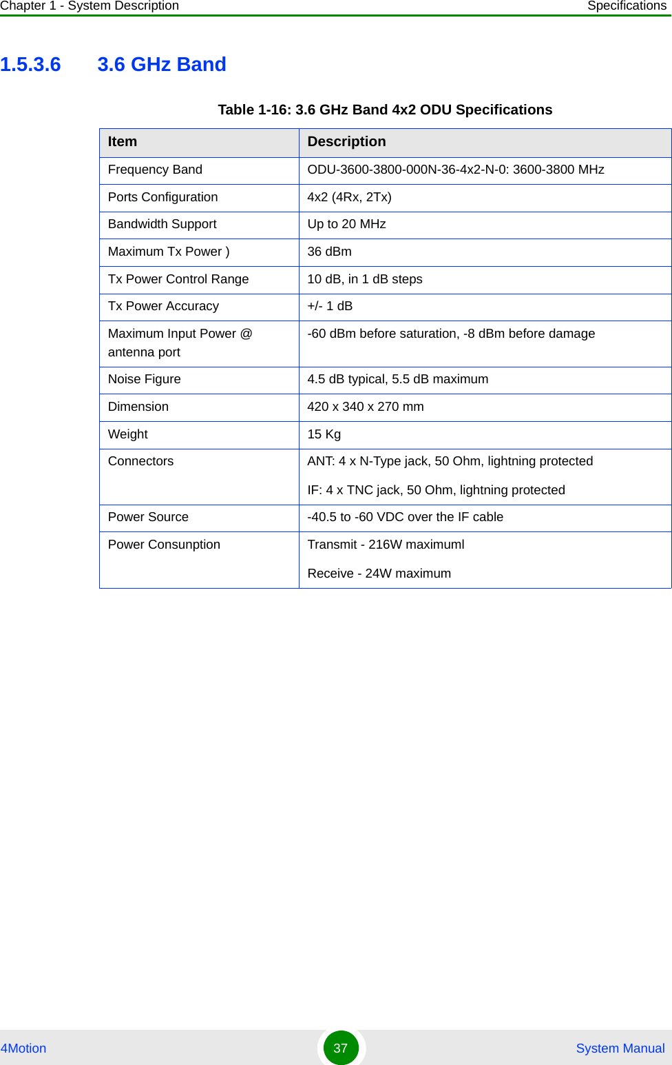
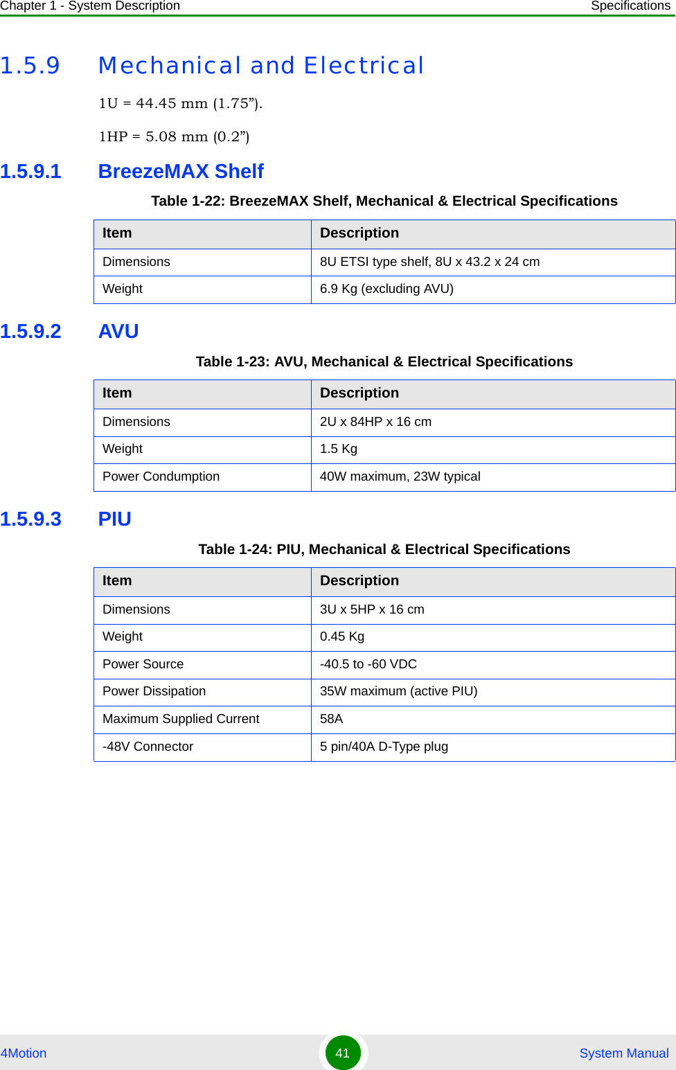
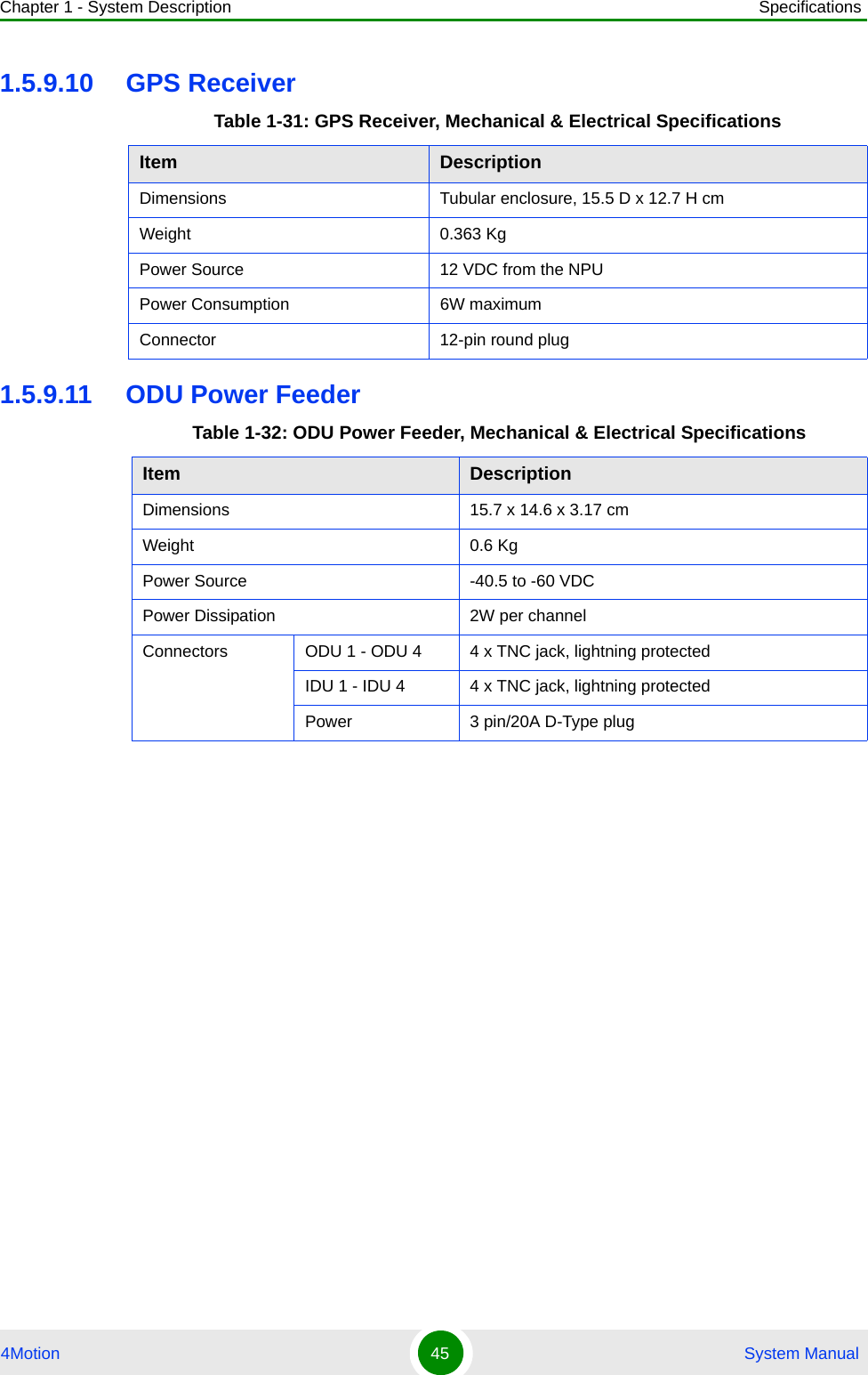
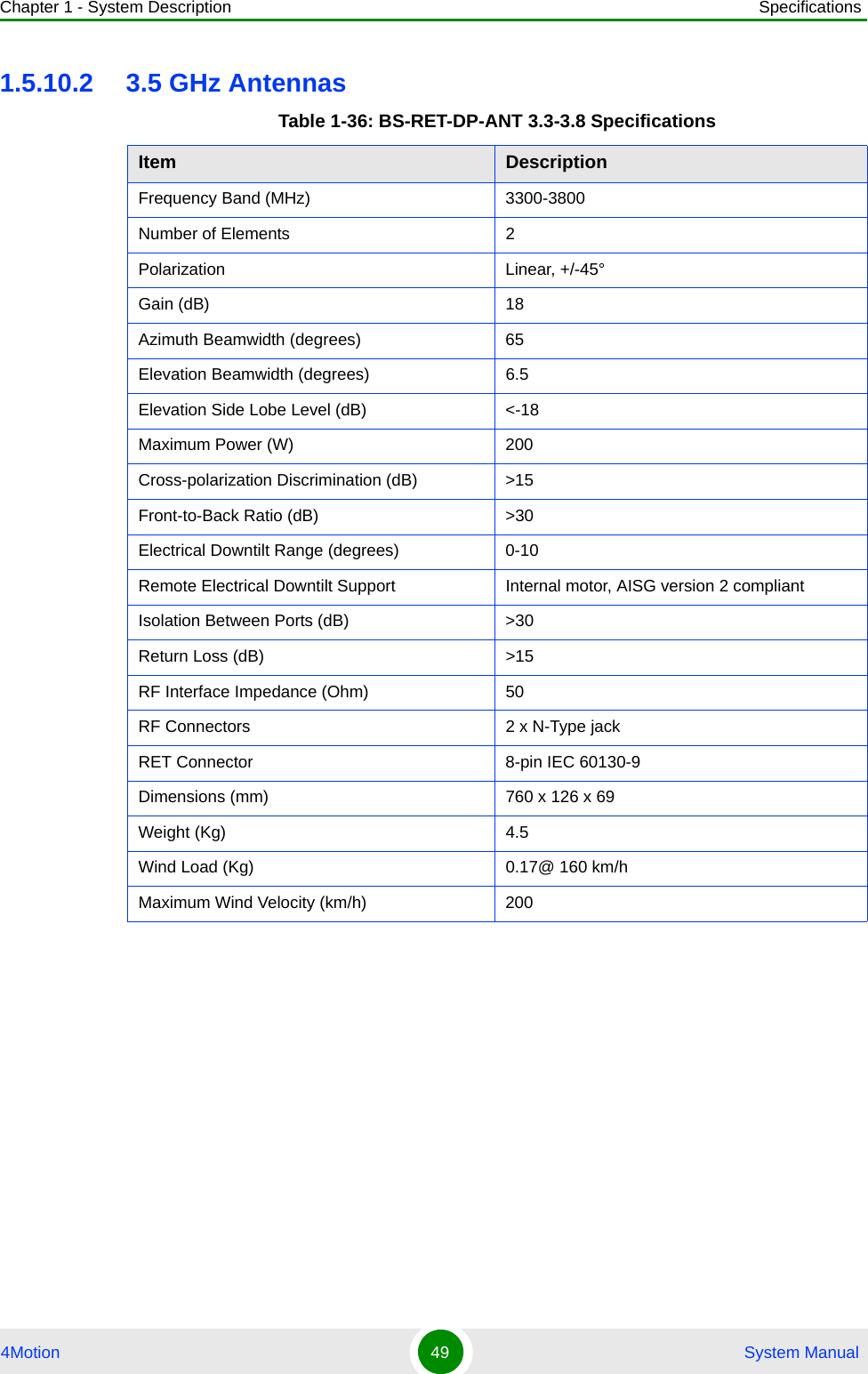
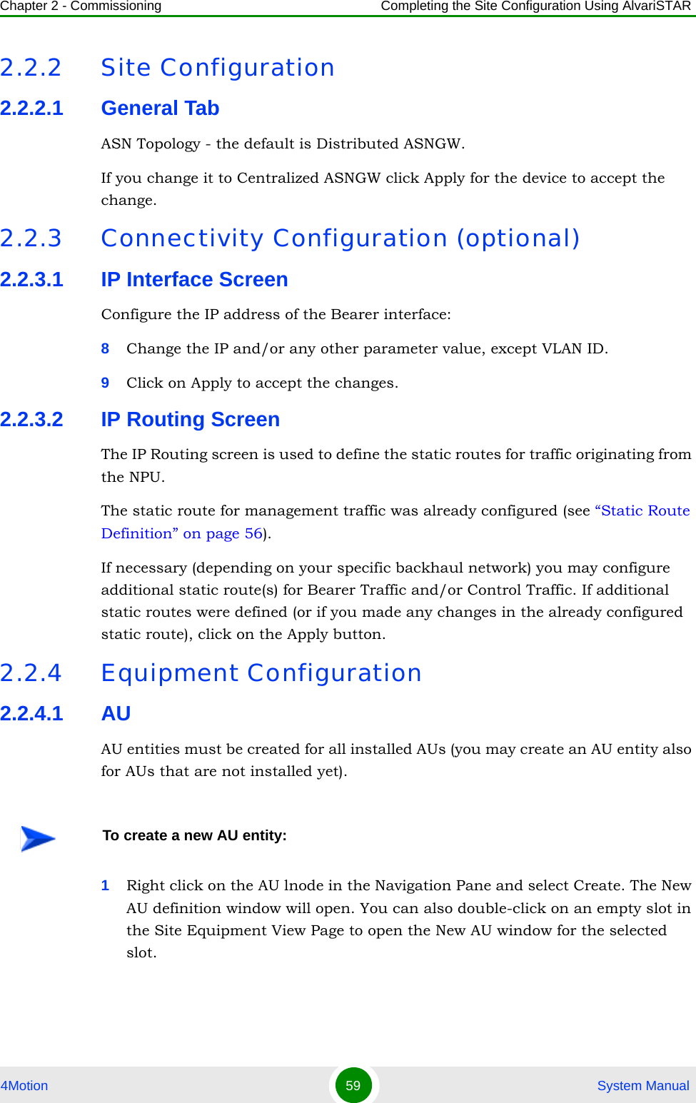
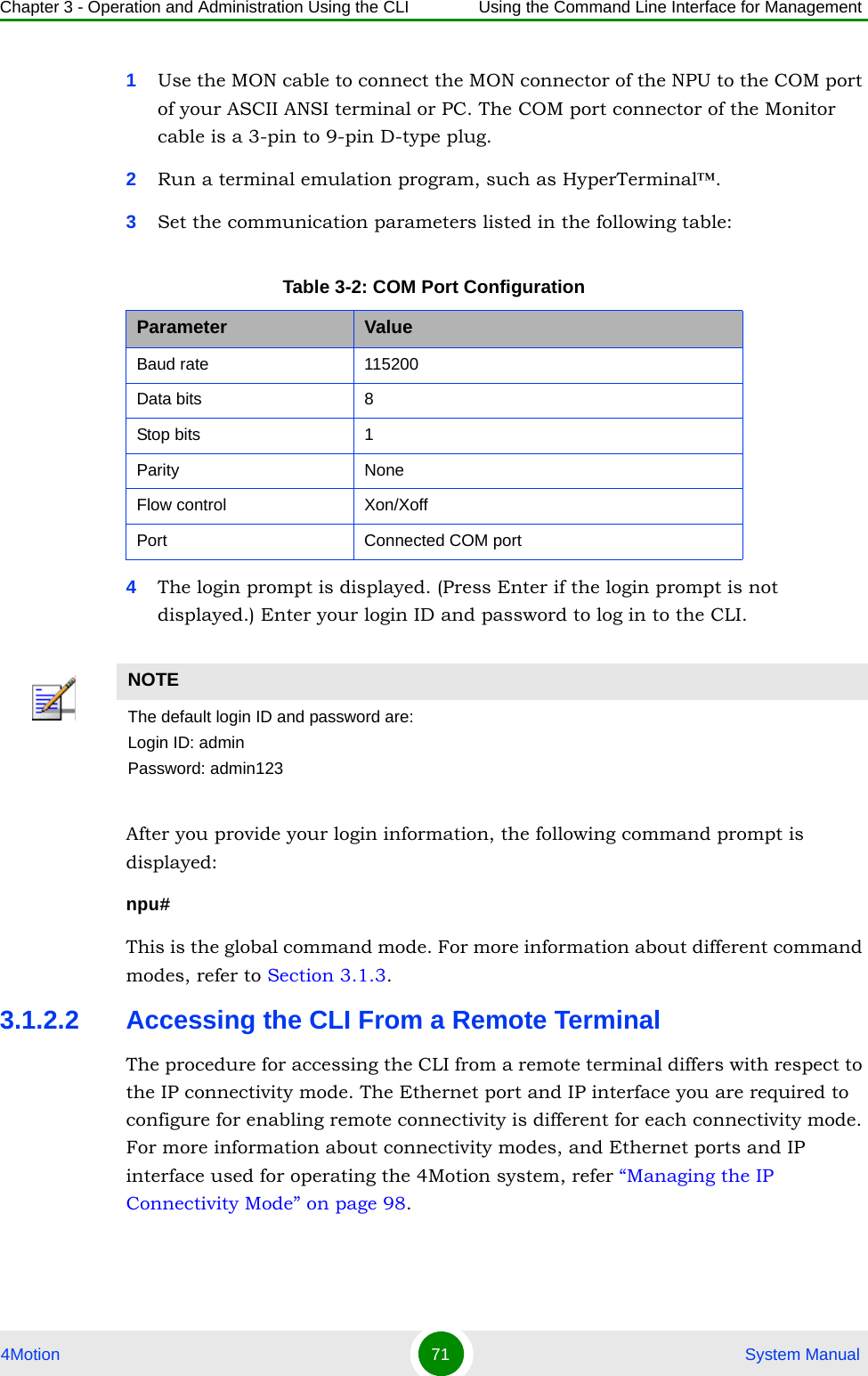
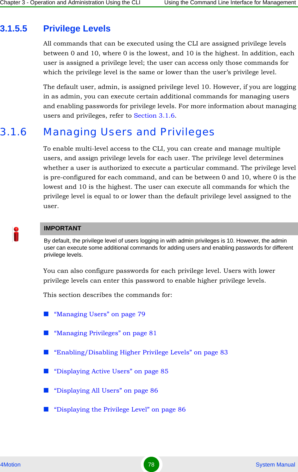
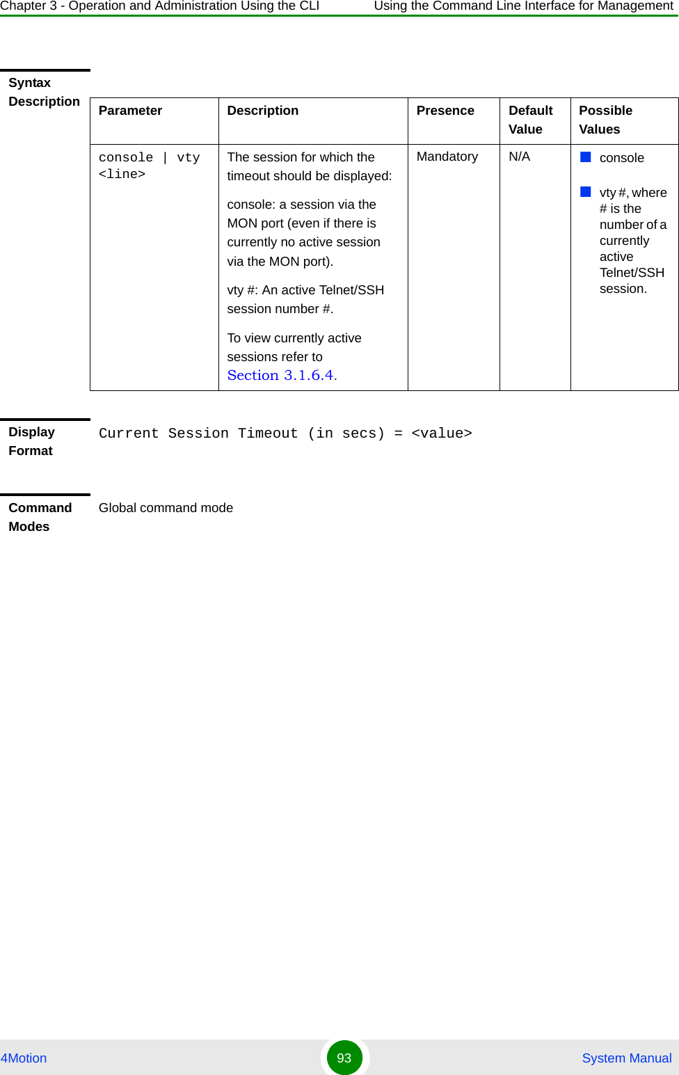
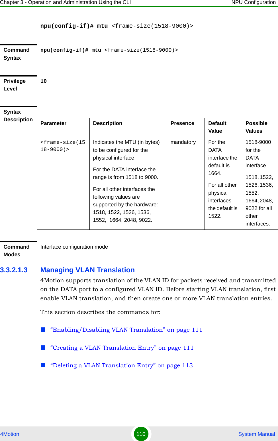
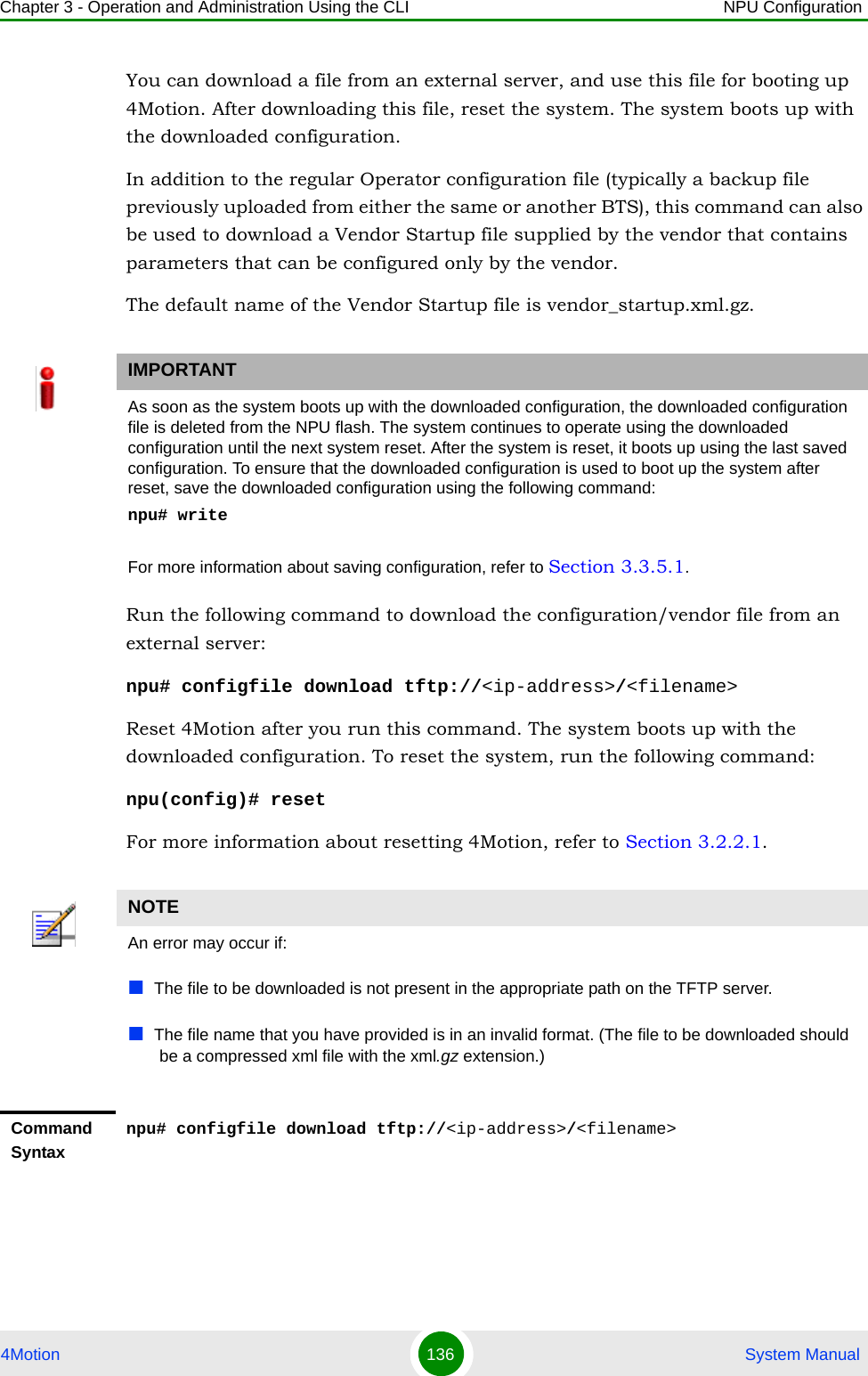
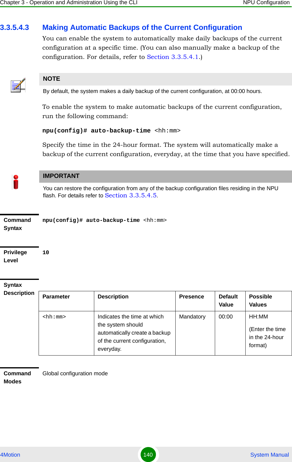
![Chapter 3 - Operation and Administration Using the CLI Using the Command Line Interface for Management4Motion 76 System Manual“Using the CLI Help” on page 76“Using the History Feature” on page 77“Using Miscellaneous Commands” on page 77“Privilege Levels” on page 783.1.5.1 Using Control CharactersControl characters refer to special characters that you can use to recall or modify previously-executed commands. The following table lists the control characters to be used for executing commands on the CLI:3.1.5.2 Using the CLI HelpThe CLI provides help that you can access while using the CLI. Execute the following command to obtain help for a specific command:help [“<text>”]Table 3-6: Control Characters for Using the CLIPress To...Up/Down arrow keys Scroll the previously executed CLI commands. Press Enter if you want to select and execute a particular command.Right/Left arrow keys Navigate to the right/left of the selected character in a command.Home key Navigate to the first character of a command.End key Navigate to the last character of a command.Backspace key Delete the characters of a command.TAB key Prompt the CLI to complete the command for which you have specified a token command. Remember that the CLI that is the nearest match to the token command that you have specified is displayed.? key View the list of commands available in the current mode. If you press ? after a command, a list of parameters available for that command is displayed.](https://usermanual.wiki/Alvarion-Technologies/BMAX-2-OR-25/User-Guide-1325752-Page-118.png)
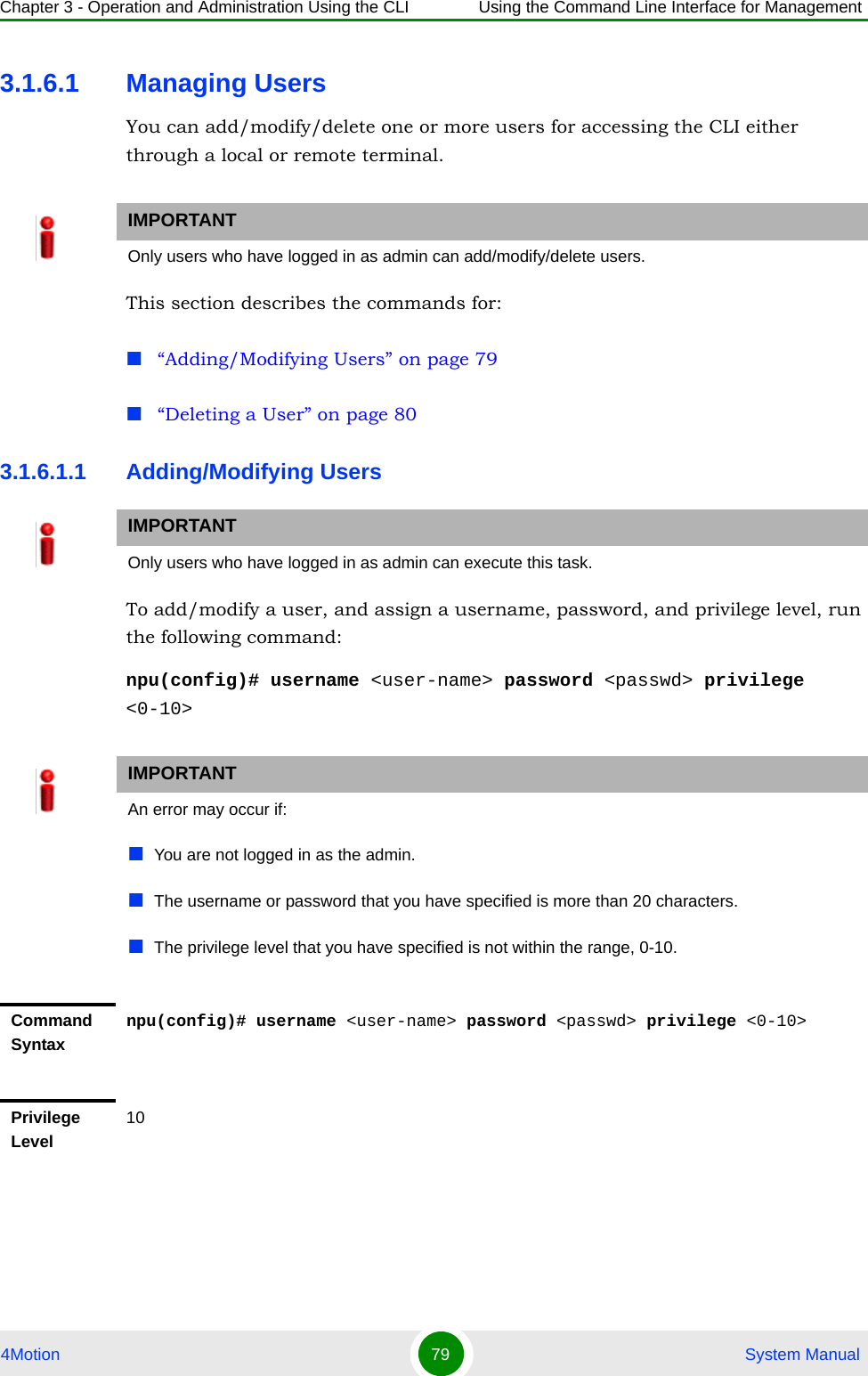
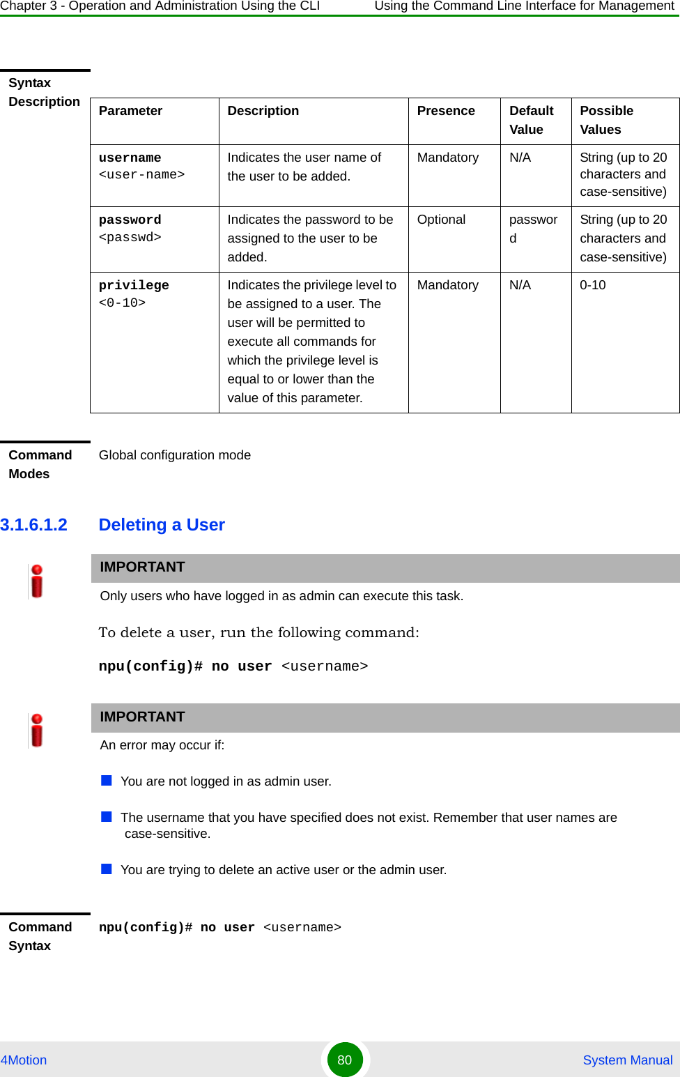
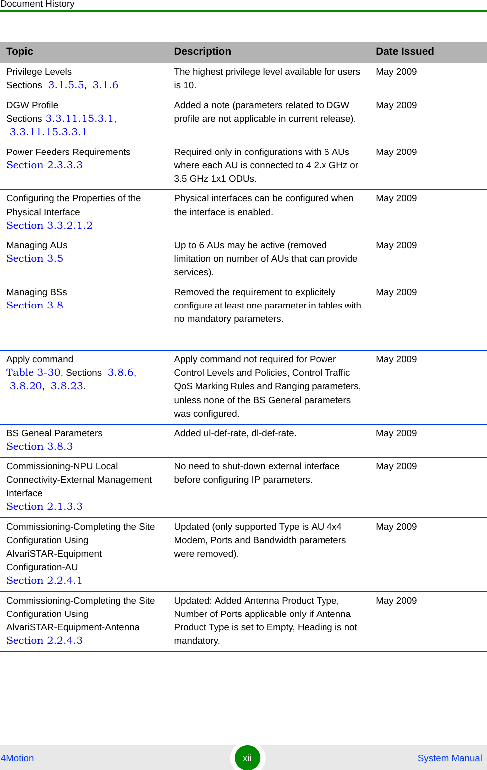
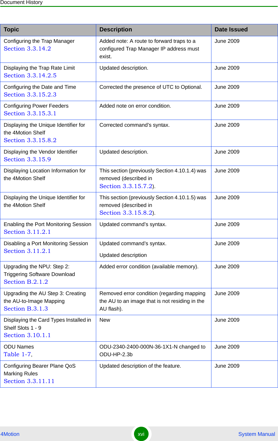
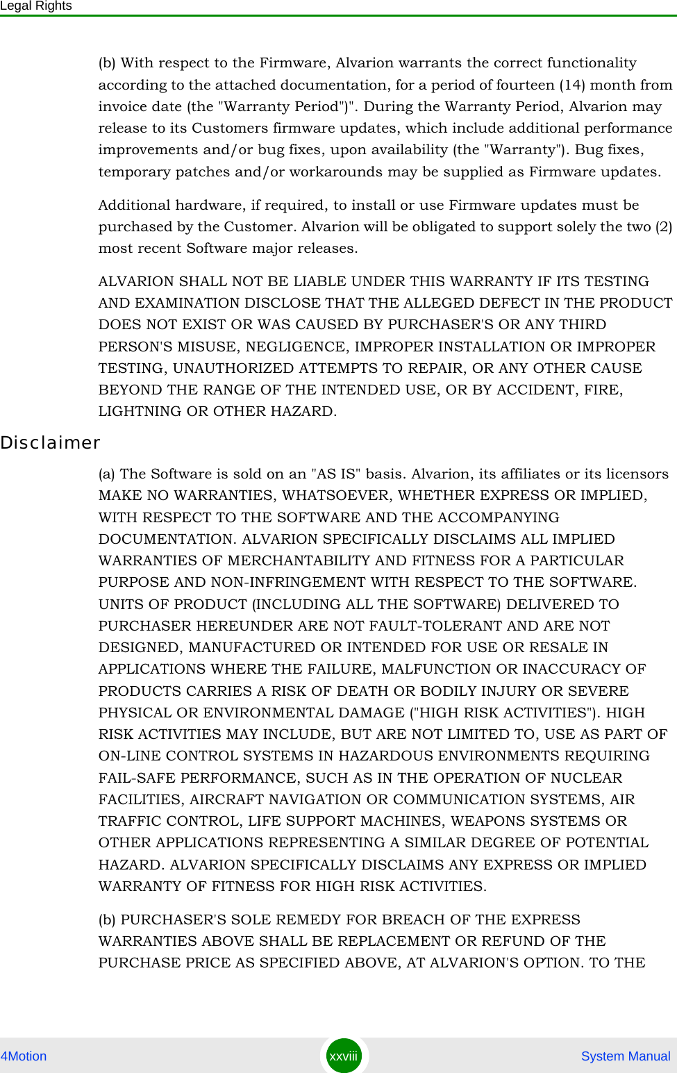
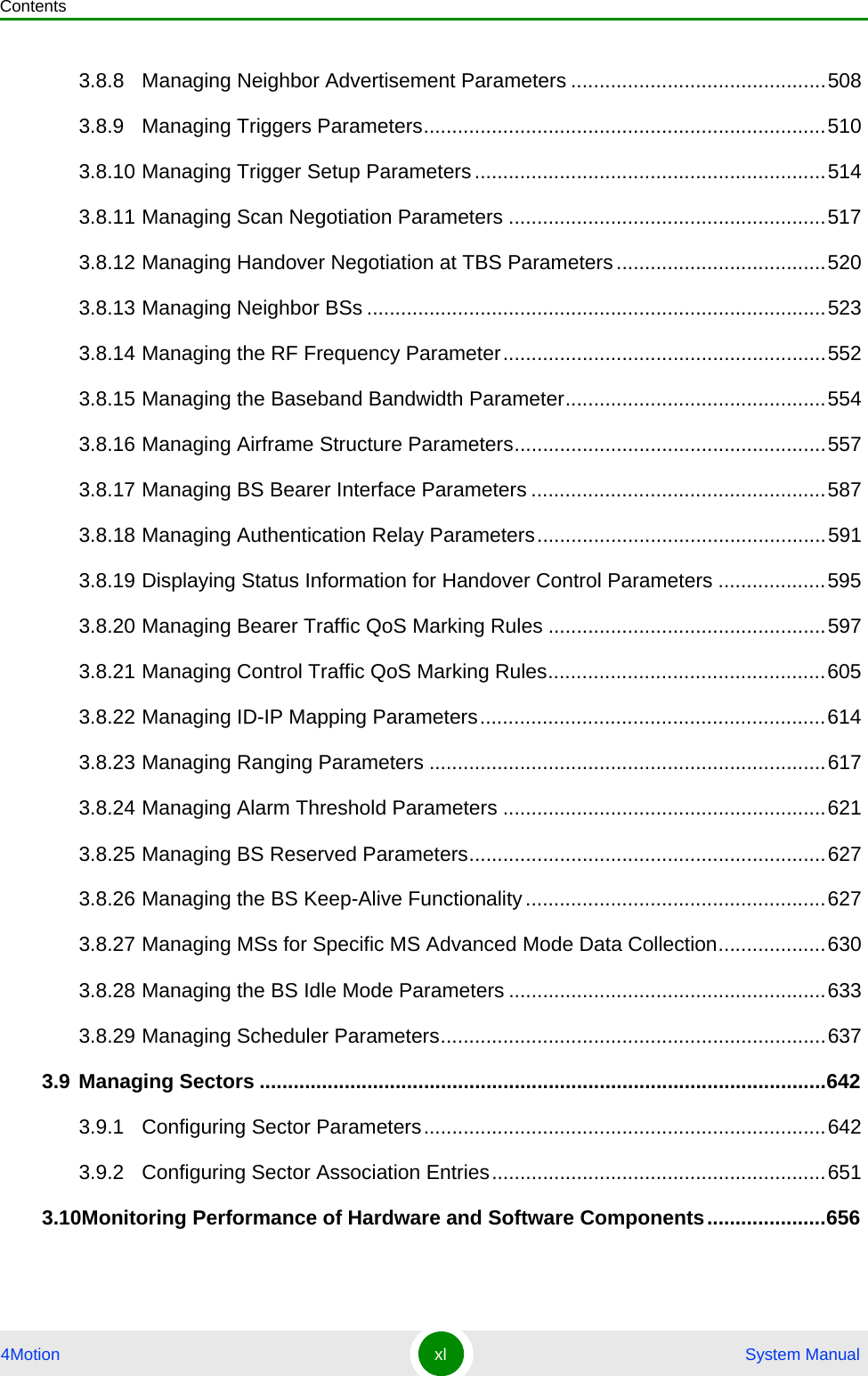
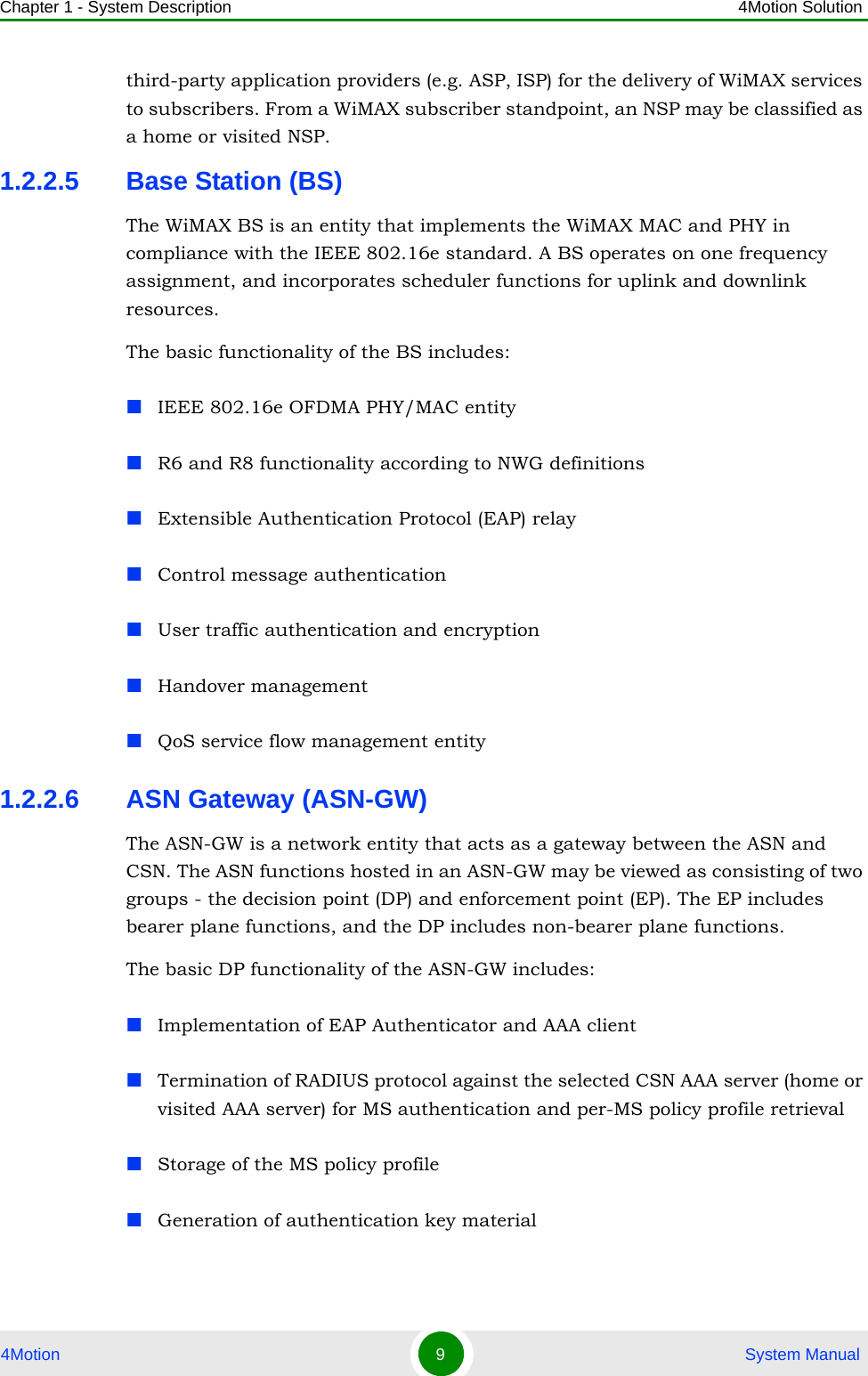
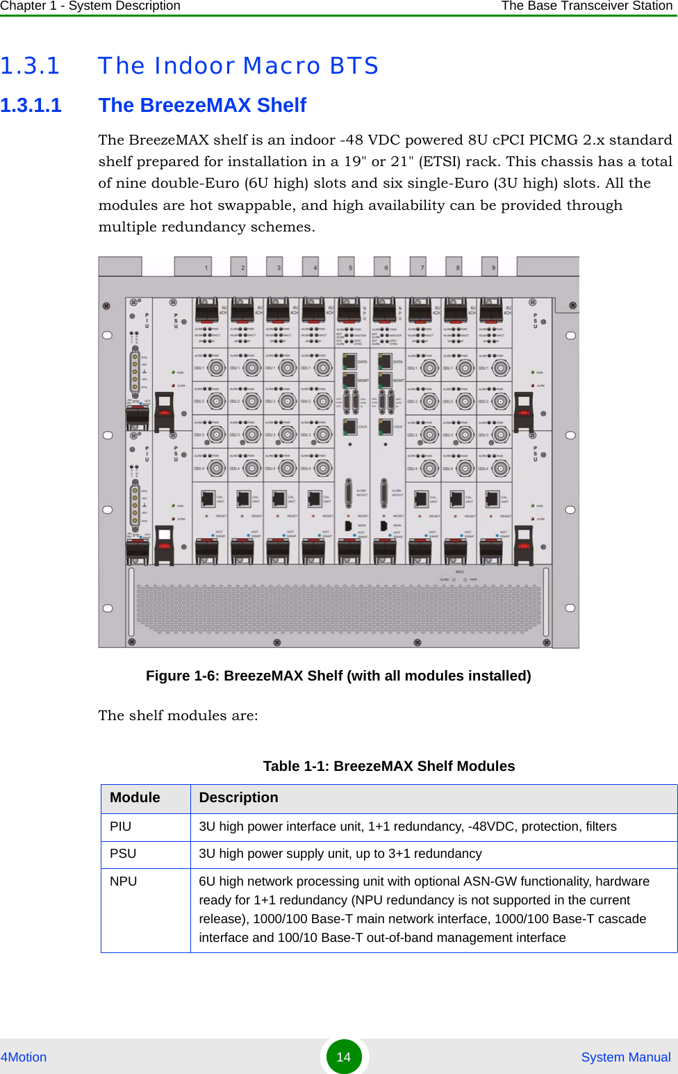
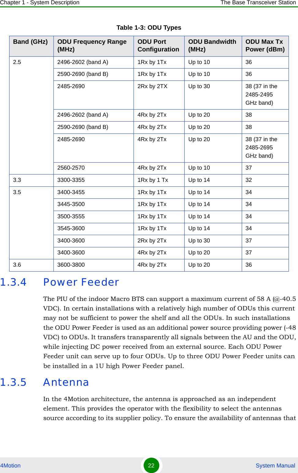
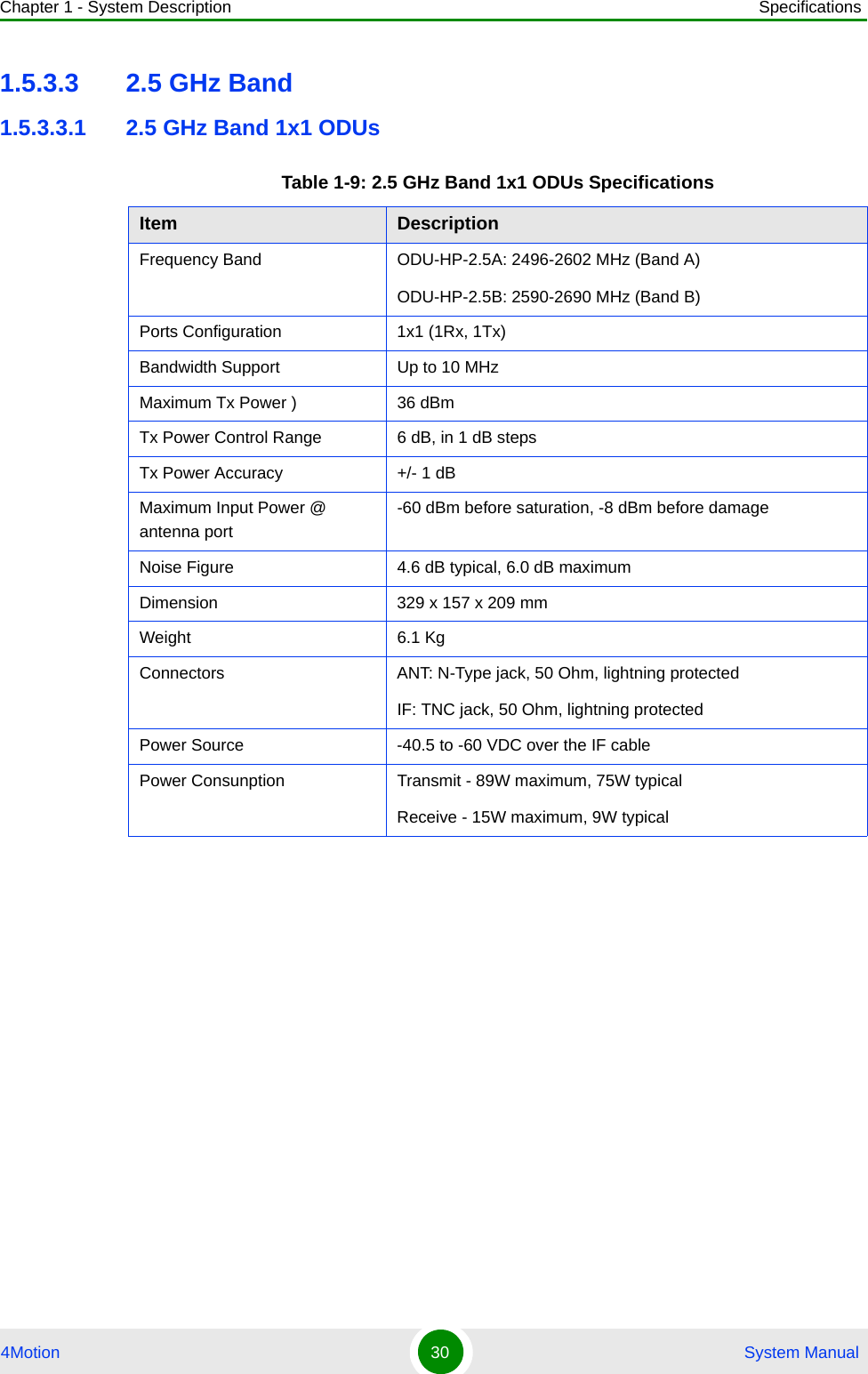
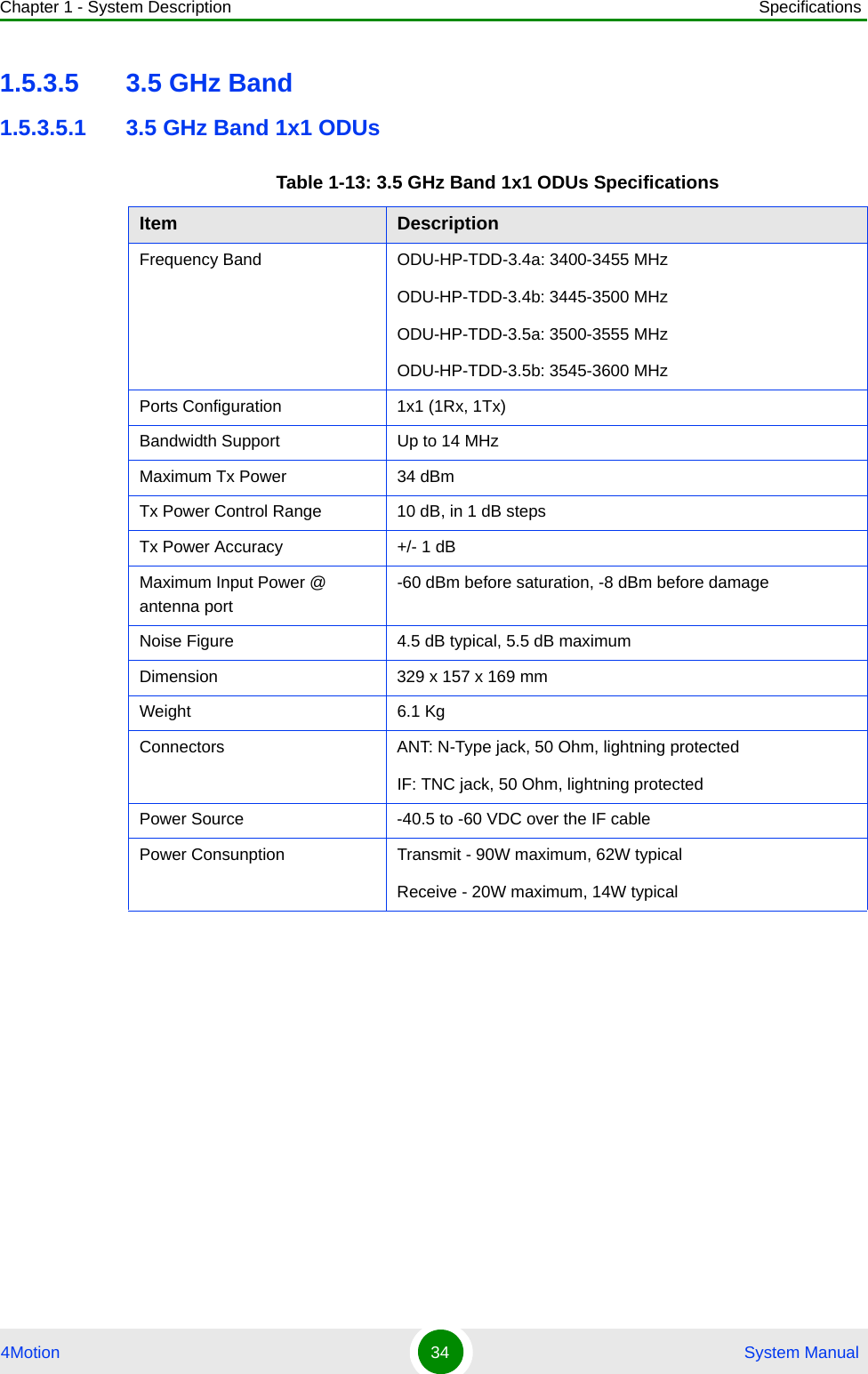
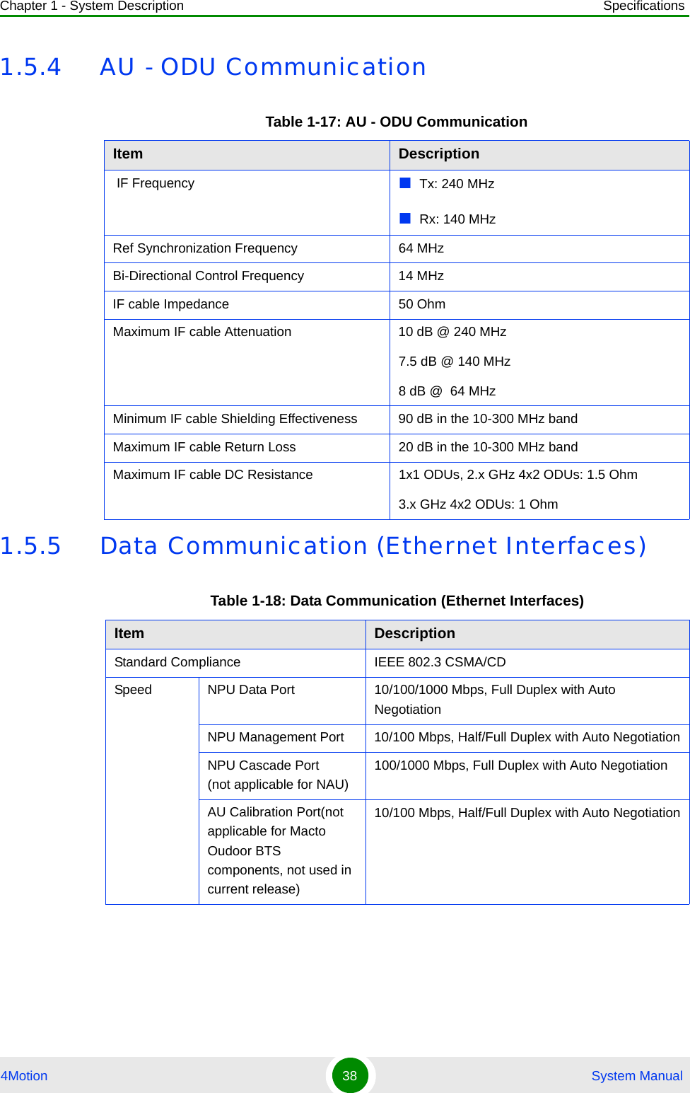
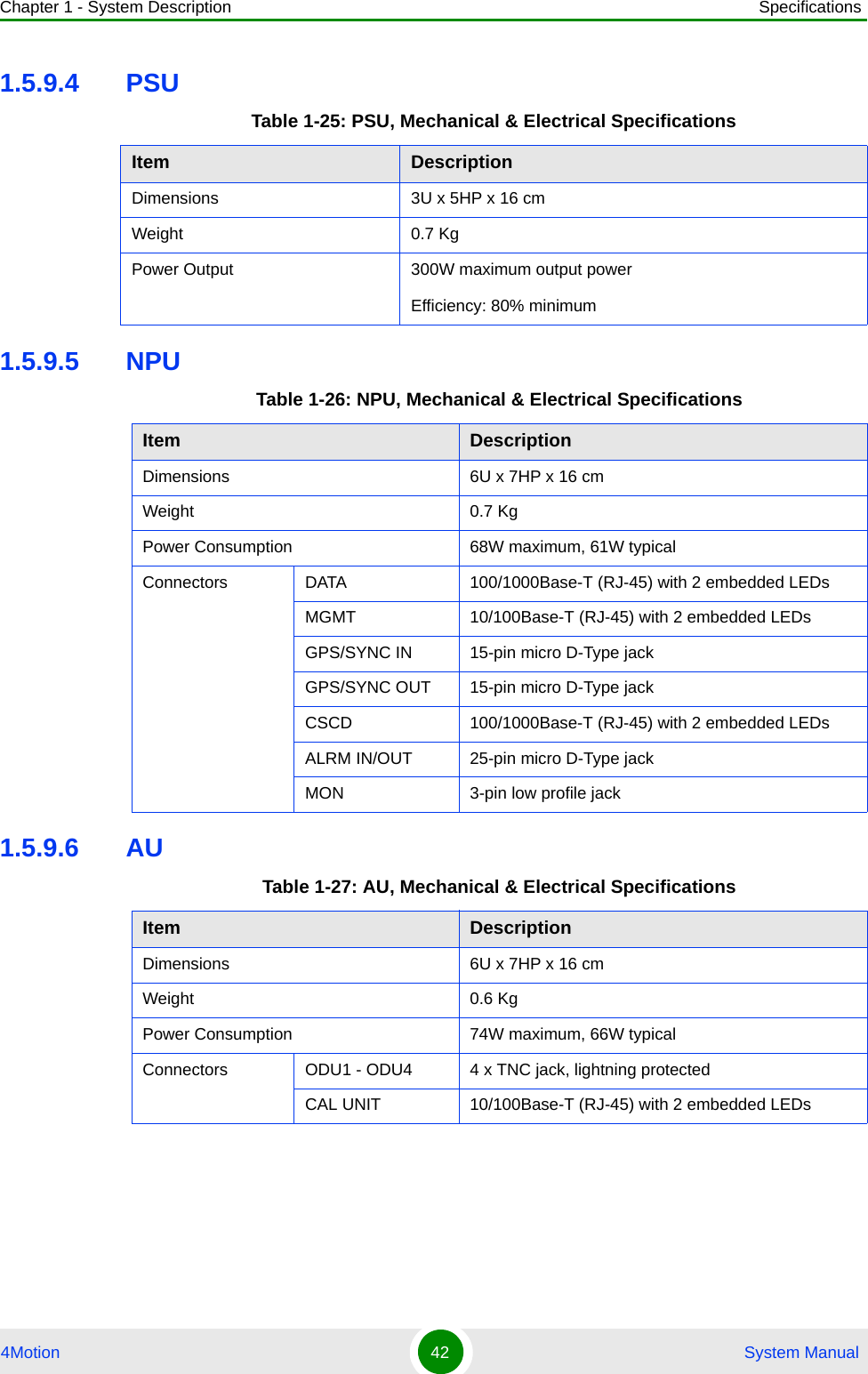
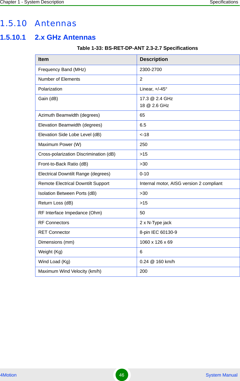
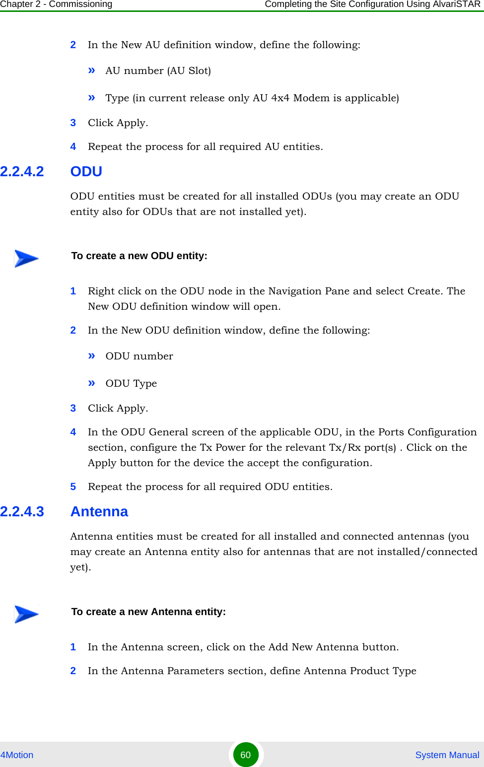
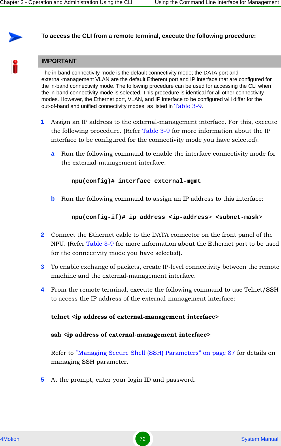
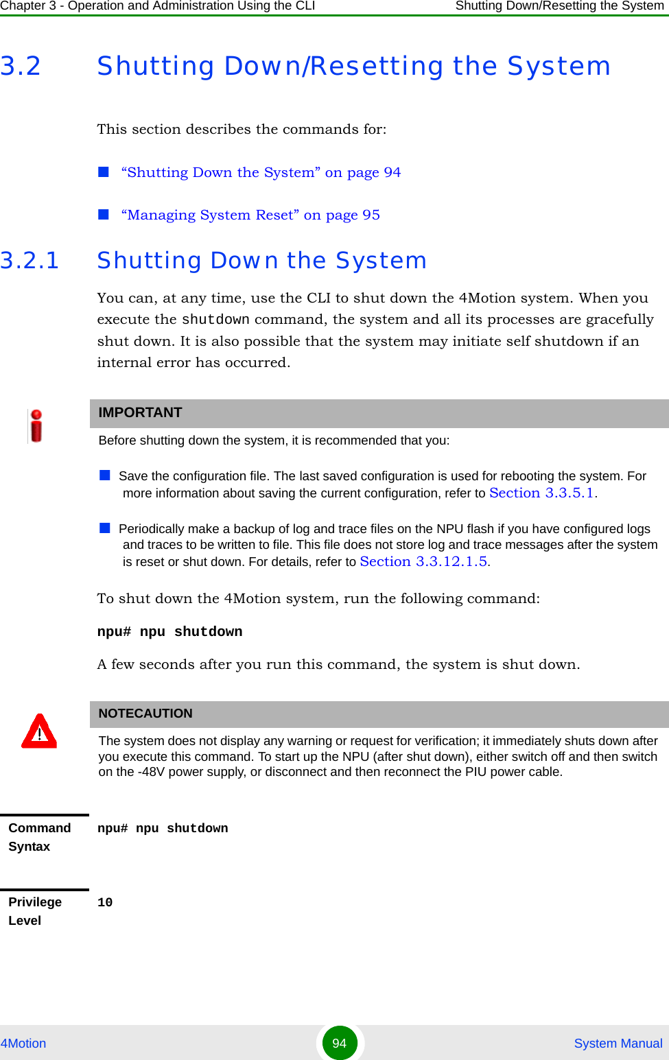
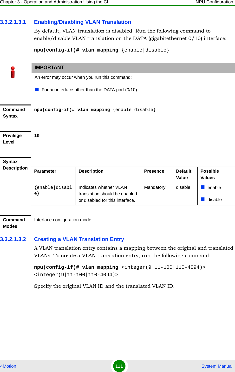
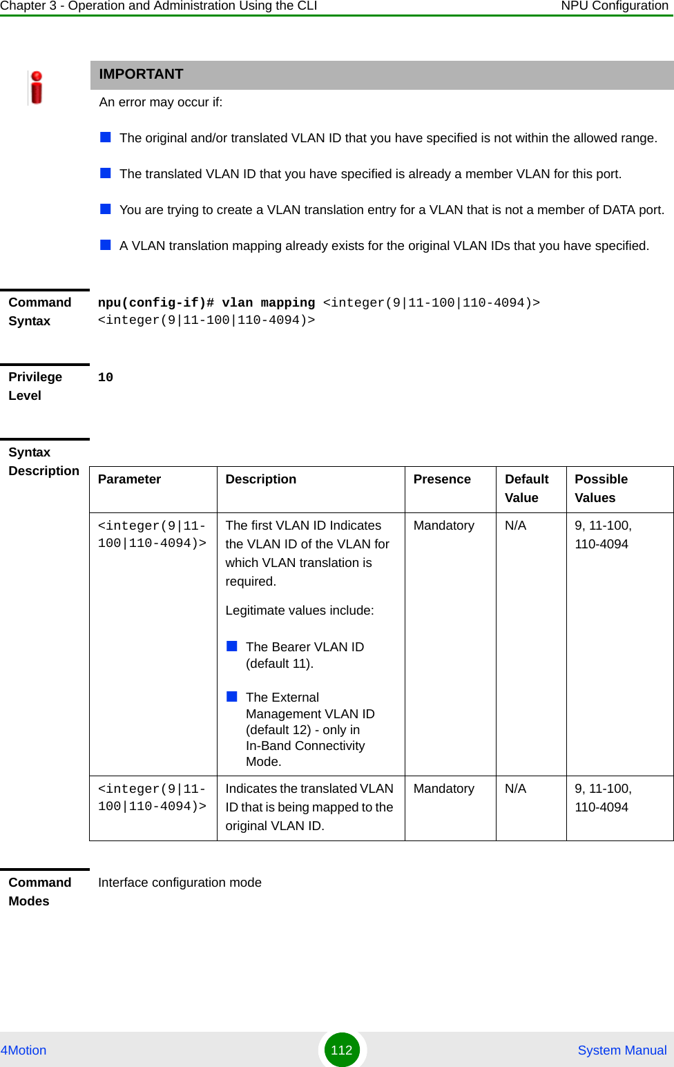
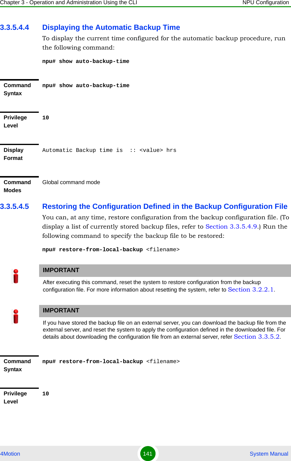
![Chapter 3 - Operation and Administration Using the CLI Using the Command Line Interface for Management4Motion 81 System Manual3.1.6.2 Managing PrivilegesTo enable users to execute commands that require a higher privilege level (than their currently configured default level), you can configure a password for each privilege level. Other users can then use the password you have specified to enable a higher privilege level. This section describes the commands for:“Assigning a Password for a Privilege Level” on page 81“Deleting a Password for a Privilege Level” on page 823.1.6.2.1 Assigning a Password for a Privilege LevelTo assign a password for a privilege level, run the following command:npu(config)# enable password [Level <0-10>] <password> Privilege Level10Syntax Description Parameter Description Presence Default ValuePossible Valuesusername <name>Indicates the username of the user to be deleted.Mandatory N/A String (upto 20 characters and case-sensitive)Command ModesGlobal configuration modeIMPORTANTOnly users who have logged in as admin can assign or delete passwords for any privilege level.IMPORTANTOnly users who have logged in as admin can execute this command.](https://usermanual.wiki/Alvarion-Technologies/BMAX-2-OR-25/User-Guide-1325752-Page-123.png)
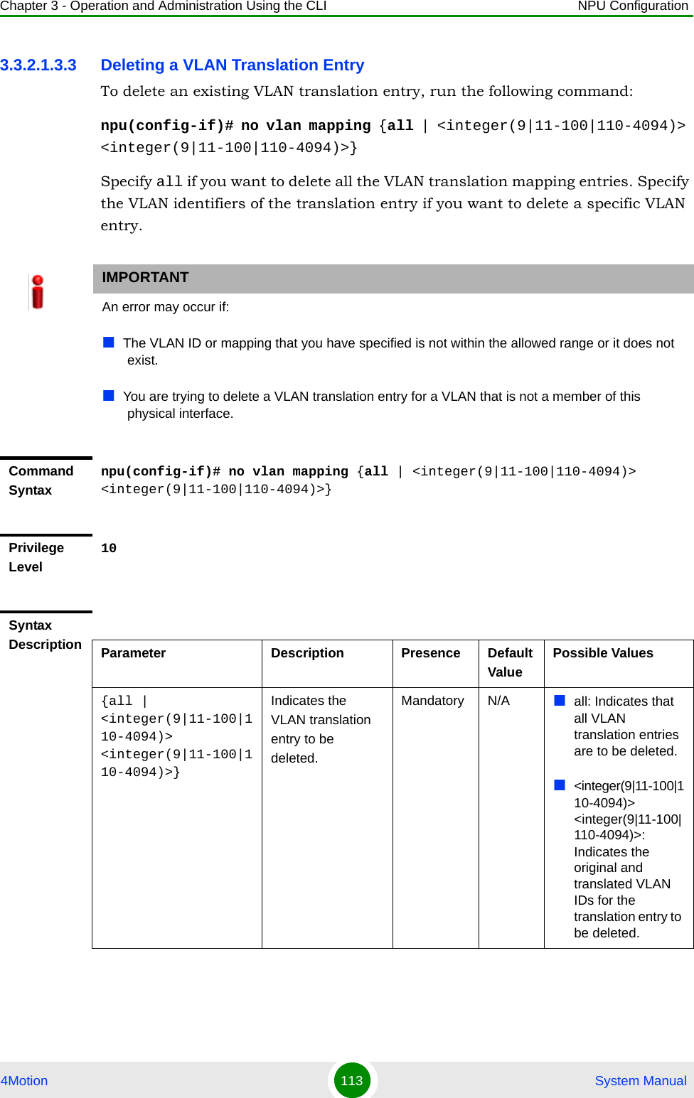
![Chapter 3 - Operation and Administration Using the CLI Using the Command Line Interface for Management4Motion 82 System Manual3.1.6.2.2 Deleting a Password for a Privilege LevelTo delete a password for a privilege level, run the following command:IMPORTANTAfter you execute this command, any user can use this password to enable the (higher) privilege level for which you have configured the password. For more information about using passwords for enabling higher privilege levels, refer Section 3.1.6.3.IMPORTANTAn error may occur if:You are trying to configure a password for a privilege level that is higher than your default privilege level. The password that you have specified is more than 20 characters.The privilege level that you have specified is not within the range, 0-10.Command Syntaxnpu(config)# enable password [Level <0-10>] <password>Privilege Level10Syntax Description Parameter Description Presence Default ValuePossible Values[Level <0-10>] Indicates the privilege level for which a password is to be enabled.Optional 10 0-10<password> Denotes the password to be assigned for the current privilege level.Mandatory N/A String (up to 20 characters and case-sensitive)Command ModesGlobal configuration modeIMPORTANTOnly users who have logged in as admin can execute this command.](https://usermanual.wiki/Alvarion-Technologies/BMAX-2-OR-25/User-Guide-1325752-Page-124.png)
![Chapter 3 - Operation and Administration Using the CLI Using the Command Line Interface for Management4Motion 83 System Manualnpu(config)# no enable password [Level <0-10>]3.1.6.3 Enabling/Disabling Higher Privilege LevelsYou can execute commands that require higher privilege levels. If the admin user has configured a password for that level, you can use that password to enable higher privilege levels.For example, if your privilege level is 1, you can provide the password configured for privilege level 10 to execute all commands that require privilege level 10.This section describes the commands for:“Enabling a Higher Privilege Level” on page 84“Returning to the Default Privilege Level” on page 85IMPORTANTAn error may occur if:The privilege level that you have specified is not within the range, 0-10.You are trying to delete a password for a privilege level that is higher than your default privilege level.Command Syntaxnpu(config)# no enable password [Level <0-10>]Privilege Level10Syntax Description Parameter Description Presence Default ValuePossible Values[Level <0-10>] Indicates the privilege level for which a password is to be disabled.Optional 10 0-10Command Syntax Global configuration mode](https://usermanual.wiki/Alvarion-Technologies/BMAX-2-OR-25/User-Guide-1325752-Page-125.png)
![Chapter 3 - Operation and Administration Using the CLI Using the Command Line Interface for Management4Motion 84 System Manual3.1.6.3.1 Enabling a Higher Privilege Level1Log in to the CLI.2Run the following command to specify the privilege level and password:npu(config)# enable [Level <0-10>]3At the password prompt, specify the password configured for the privilege level that you have specified.If you specify the correct password, you are logged in to the CLI with the privilege level that you had specified. You can now execute all commands that require the current privilege level.You can, at any time, return to your default privilege level. For details, refer Section 3.1.6.3.2.To enable a higher privilege level:NOTEYou can display your current privilege level, using the following command:npu# show privilege NOTEAn error may occur if:You have specified an incorrect password. Remember that all passwords are case-sensitive.No password is not configured for the privilege level you are trying to access.Command Syntaxnpu(config)# enable [Level <0-10>]Privilege Level10](https://usermanual.wiki/Alvarion-Technologies/BMAX-2-OR-25/User-Guide-1325752-Page-126.png)
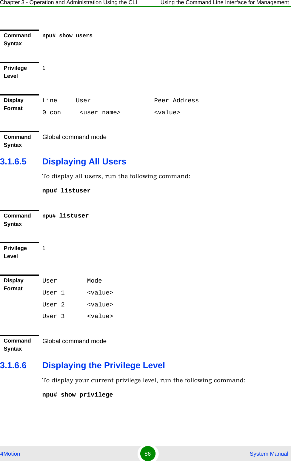
![Chapter 3 - Operation and Administration Using the CLI Using the Command Line Interface for Management4Motion 85 System Manual3.1.6.3.2 Returning to the Default Privilege LevelRun the following command to disable the current privilege level, and return to your default privilege level:npu(config)# disable [Level <0-10>]After you run this command, you automatically return to your default privilege level. You can display your current privilege level, using the following command:npu# show privilege 3.1.6.4 Displaying Active UsersTo display all active users, run the following command:npu# show usersSyntax Description Parameter Description Presence Default ValuePossible Values[Level <0-10>] Indicates the privilege level you want to enable.Mandatory N/A 0-10Command ModesGlobal configuration modeCommand Syntaxnpu(config)# disable [Level <0-10>]Privilege Level1Syntax Description Parameter Description Presence Default ValuePossible Values[Level <0-10>] Indicates the privilege level you want to disable.Mandatory N/A 0-10Command ModesGlobal command mode](https://usermanual.wiki/Alvarion-Technologies/BMAX-2-OR-25/User-Guide-1325752-Page-127.png)
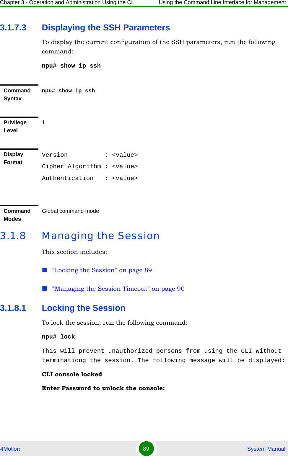
![Chapter 3 - Operation and Administration Using the CLI Using the Command Line Interface for Management4Motion 87 System Manual3.1.7 Managing Secure Shell (SSH) ParametersThe SSH parameters define the parameters used for establishing remote secure access to the device using SSH protocol rather than the plaintext-based insecure Telnet protocol.This section includes:“Configuring SSH Parameters” on page 87“Restoring the Default Values of SSH Parameters” on page 88“Displaying the SSH Parameters” on page 893.1.7.1 Configuring SSH ParametersTo configure SSH parameters, run the following command:npu(config)# ip ssh {version compatibility | cipher ([des-cbc] [3des-cbc]) | auth ([hmac-md5] [hmac-sha1]) }Command Syntaxnpu# show privilegePrivilege Level1Display FormatCurrent privilege level is <value>Command SyntaxGlobal command modeCommand Syntaxnpu(config)# ip ssh {version compatibility | cipher ([des-cbc] [3des-cbc]) | auth ([hmac-md5] [hmac-sha1]) }Privilege Level10](https://usermanual.wiki/Alvarion-Technologies/BMAX-2-OR-25/User-Guide-1325752-Page-129.png)
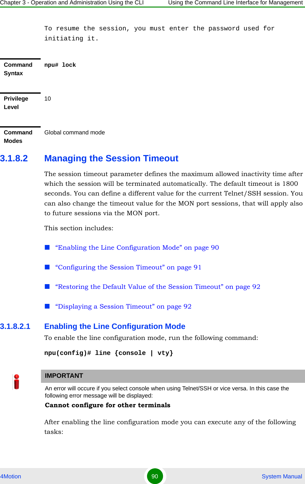
![Chapter 3 - Operation and Administration Using the CLI Using the Command Line Interface for Management4Motion 88 System Manual3.1.7.2 Restoring the Default Values of SSH ParametersTo restore the default value of one or more SSH parameters, run the following command:npu(config)# no ip ssh {version compatibility | cipher ([des-cbc] [3des-cbc]) | auth ([hmac-md5] [hmac-sha1]) }.To restore the default values of all SSH parameters run the following command:npu(config)# no ip sshSyntax Description Parameter Description Presence Default ValuePossible Valuesversion compatibilityThe SSH version that can be used: The default is SSH version 2. The command npu(config)# ip ssh version compatibility enables compatibility with both SSH version 1 and SSH version 2.Optional SSH2 version compatibilitycipher ([des-cbc] [3des-cbc])The encryption algorithm used by the SSH protocol: DES-CCBC or 3DES-CBC.Optional des-cbc des-cbc3des-cbcauth ([hmac-md5] [hmac-sha1])The authentication mechanism used by the SSH protocol: HMAC-MD5 or HMAC-SHA1.OPtional hmac-sha1hmac-md5hmac-sha1Command ModesGlobal configuration modeCommand Syntaxnpu(config)# no ip ssh {version compatibility | cipher ([des-cbc] [3des-cbc]) | auth ([hmac-md5] [hmac-sha1]) }Privilege Level10Command ModesGlobal configuration mode](https://usermanual.wiki/Alvarion-Technologies/BMAX-2-OR-25/User-Guide-1325752-Page-130.png)

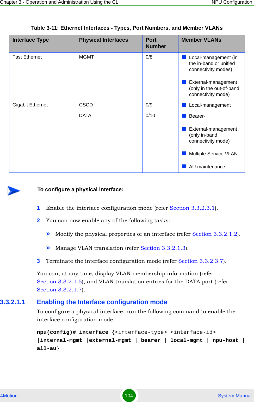
![Chapter 3 - Operation and Administration Using the CLI NPU Configuration4Motion 114 System Manual3.3.2.1.4 Terminating the Interface Configuration ModeTo terminate the interface configuration mode, run the following command:npu(config-if)# exit3.3.2.1.5 Displaying VLAN Membership InformationRun the following command to display Ethernet interfaces that are members of a particular or all VLAN:npu# show vlan [id <vlan-id(11-4094)>]Do not specify the VLAN ID if you want to view membership information for all VLANs.Command ModesGlobal command modeCommand Syntaxnpu(config-if)# exitPrivilege Level10Command ModesInterface configuration modeCommand Syntaxnpu# show vlan [id <vlan-id(11-4094)>]Privilege Level1](https://usermanual.wiki/Alvarion-Technologies/BMAX-2-OR-25/User-Guide-1325752-Page-156.png)
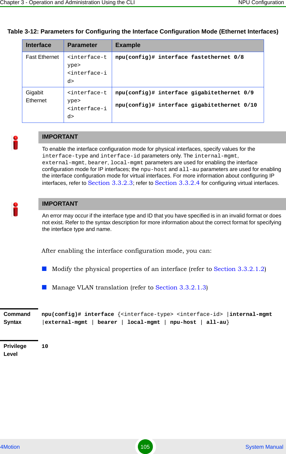
![Chapter 3 - Operation and Administration Using the CLI NPU Configuration4Motion 115 System Manual3.3.2.1.6 Displaying VLAN Configuration Information for Physical InterfacesTo display the configuration information for a VLAN that is bound to a particular physical interface, run the following command:npu# show vlan port config [port <interface-type> <interface-id>]Do not specify the port number and type if you want to display configuration information for all physical interfaces. Syntax Description Parameter Description Presence Default ValuePossible Values[id <vlan-id(11-4094)>]Indicates the VLAN ID for which membership information is to be displayed. Do not specify any value for this parameter if you want to view VLAN membership information for all VLANs.Mandatory N/A 11-4096Display FormatVlan Name Ports ---- ---- ----- <VLAN ID <>VLAN Name> <member ports><VLAN ID <>VLAN Name> <member ports>Command ModesGlobal command modeIMPORTANTAn error may occur if you specify an interface type or ID that does not exist.Command Syntaxnpu# show vlan port config [port <interface-type> <interface-id>]Privilege Level1](https://usermanual.wiki/Alvarion-Technologies/BMAX-2-OR-25/User-Guide-1325752-Page-157.png)
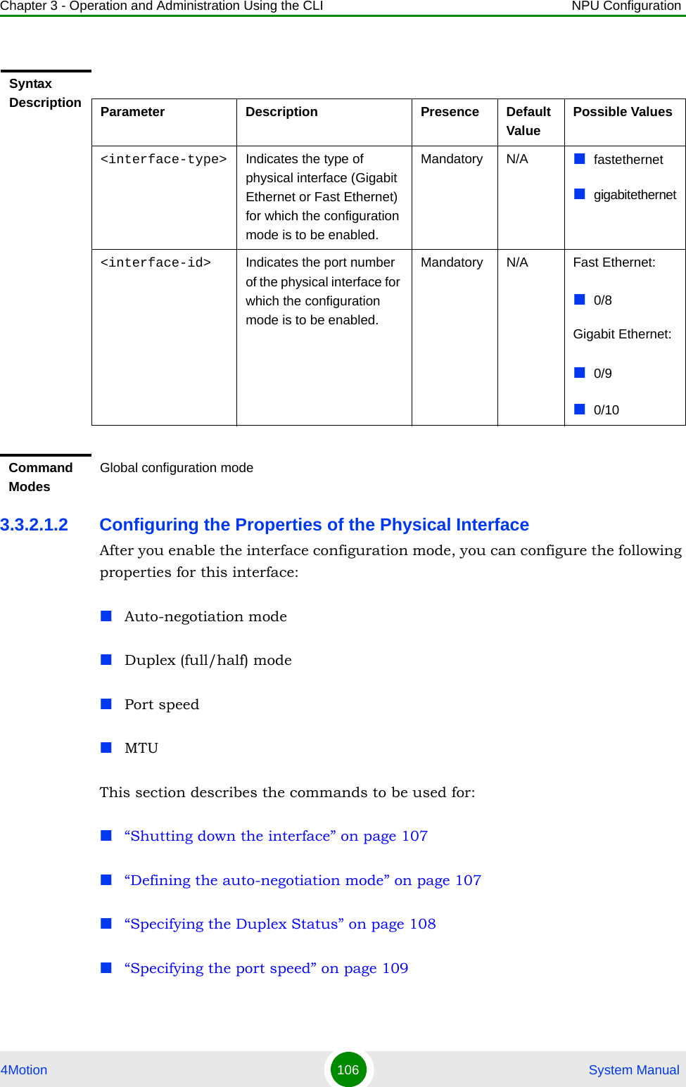
![Chapter 3 - Operation and Administration Using the CLI NPU Configuration4Motion 125 System Manual3.3.2.3.7 Terminating the Interface Configuration ModeTo terminate the interface configuration mode, run the following command:npu(config-if)# exit3.3.2.3.8 Displaying IP Interface Status and Configuration InformationTo display the status and configuration information for an IP interface, run the following command:npu# show ip interface [{internal-mgmt | external-mgmt | bearer | local-mgmt}]Do not specify the interface if you want to view configuration information for all IP interfaces.Privilege Level10Syntax Description Parameter Description Presence Default ValuePossible Values<frame-size(68-1500)>Indicates the MTU (in bytes) to be configured for the IP interface.mandatory 1500 68-1500Command ModesInterface configuration modeCommand Syntaxnpu(config-if)# exitPrivilege Level10Command ModesInterface configuration modeIMPORTANTAn error may occur if the IP interface does not exist for the configured connectivity and boot mode.](https://usermanual.wiki/Alvarion-Technologies/BMAX-2-OR-25/User-Guide-1325752-Page-167.png)
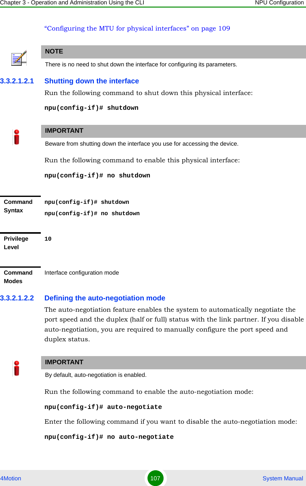
![Chapter 3 - Operation and Administration Using the CLI NPU Configuration4Motion 126 System Manual3.3.2.4 Configuring Virtual InterfacesIn addition to physical and IP interfaces, 4Motion defines the following virtual interfaces. All ACLs configured for filtering traffic destined towards the NPU or AUs, are attached to either of these interfaces.NPU-host: Used for configuring ACLs to filter traffic destined towards the NPU.All-AU: Used for configuring ACLs to filter traffic destined towards the AUs in the 4Motion shelf. For more information about attaching ACLs to the NPU or all-AUs, refer the section, “Attaching/De-attaching ACLs to/from an Interface” on page 199.Command Syntaxnpu# show ip interface [{internal-mgmt | external-mgmt | bearer | local-mgmt}]Privilege Level1Syntax Description Parameter Description Presence Default ValuePossible Values{internal-mgmt | external-mgmt | bearer | local-mgmt}Indicates the interface for which configuration information is to be displayed.Do not specify any value for this parameter if you want to view configuration information for all IP interfaces.Optional N/A internal-mgmtexternal-mgmtbearerlocal-mgmtDisplay Format<Interface Name> is <up/down> Internet Address is <value>Broadcast Address <value>Command ModesGlobal command mode](https://usermanual.wiki/Alvarion-Technologies/BMAX-2-OR-25/User-Guide-1325752-Page-168.png)
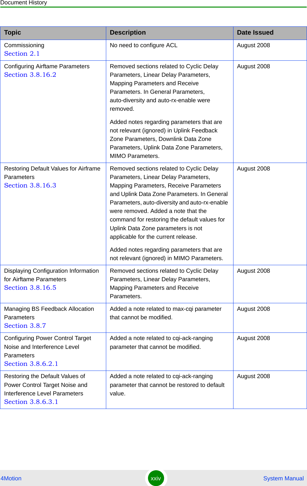
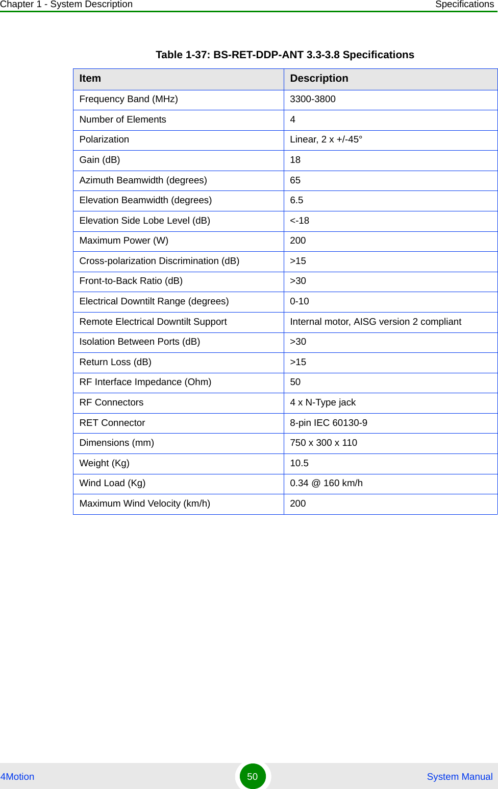
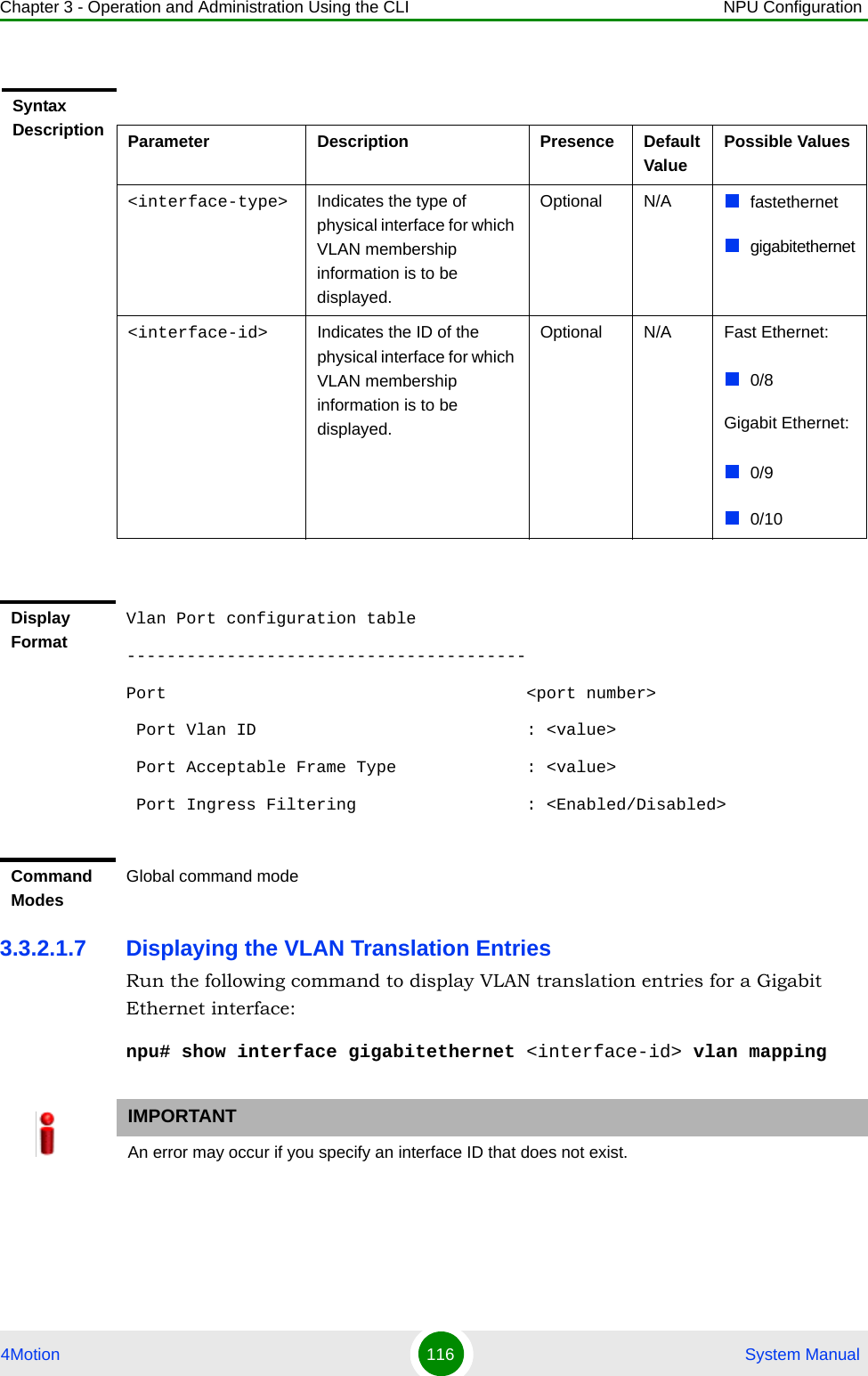
![Chapter 3 - Operation and Administration Using the CLI NPU Configuration4Motion 127 System Manual3.3.2.5 Displaying Status and Configuration Information for Physical, IP, and Virtual InterfacesTo display the status and configuration information for physical, IP and/or virtual interfaces, run the following command:npu# show interfaces [{[<interface-type> <interface-id>] | internal-mgmt | external-mgmt | bearer | local-mgmt | npu-host | all-au}]To display the configuration information for all interfaces, do not specify a value for any parameter.The following table lists parameters to be specified with respect to the type of interface for which configuration information is to be displayed:Table 3-14: Parameters for Displaying Configuration Information for Physical, IP, and Virtual InterfacesInterface Parameters ExampleAll Interfaces None npu# show interfacesPhysical InterfacesFast Ethernet:<interface-type> <interface-id>npu# show interfaces fastethernet 0/8 Gigabit Ethernet<interface-type> <interface-id>npu# show interfaces gigabitethernet 0/9 npu# show interfaces gigabitethernet 0/10 IP Interfaces internal-mgmt npu# show interfaces internal-mgmt external-mgmt npu# show interfaces external-mgmt bearer npu# show interfaces bearer local-mgmt npu# show interfaces local-mgmt Virtual Interfacesnpu-host npu# show interfaces npu-hostall-au npu# show interfaces all-auIMPORTANTAn error may occur if:The interface type or ID that you have specified does not exist.The IP interface does not exist for the configured connectivity and boot mode.](https://usermanual.wiki/Alvarion-Technologies/BMAX-2-OR-25/User-Guide-1325752-Page-169.png)
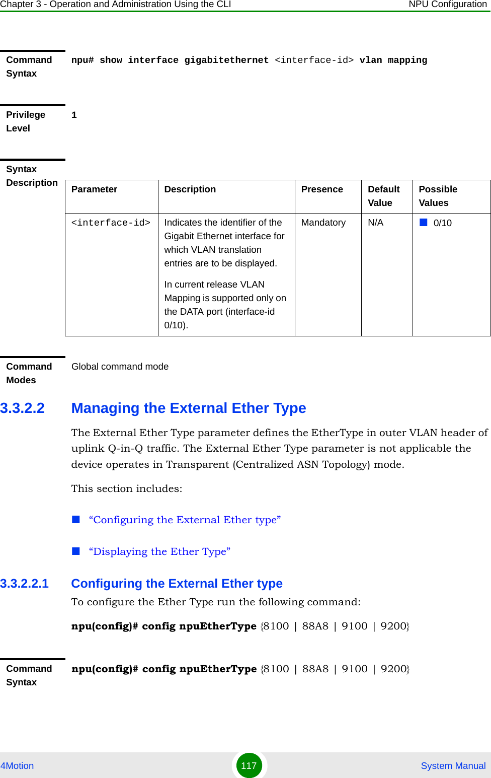
![Chapter 3 - Operation and Administration Using the CLI NPU Configuration4Motion 128 System ManualCommand Syntaxnpu# show interfaces [{[<interface-type> <interface-id>] | internal-mgmt | external-mgmt | bearer | local-mgmt | npu-host | all-au}]Privilege Level1Syntax Description Parameter Description Presence Default ValuePossible Values[{[<interface-type> <interface-id>] | internal-mgmt | external-mgmt | bearer | local-mgmt | npu-host | all-au}]Indicates the type of interface (physical, IP, or virtual) for which configuration information is to be displayed. Do not specify any value for this parameter if you want to display configuration information for all physical, IP, and virtual interfaces.Optional N/A Refera Table 3-14a.](https://usermanual.wiki/Alvarion-Technologies/BMAX-2-OR-25/User-Guide-1325752-Page-170.png)
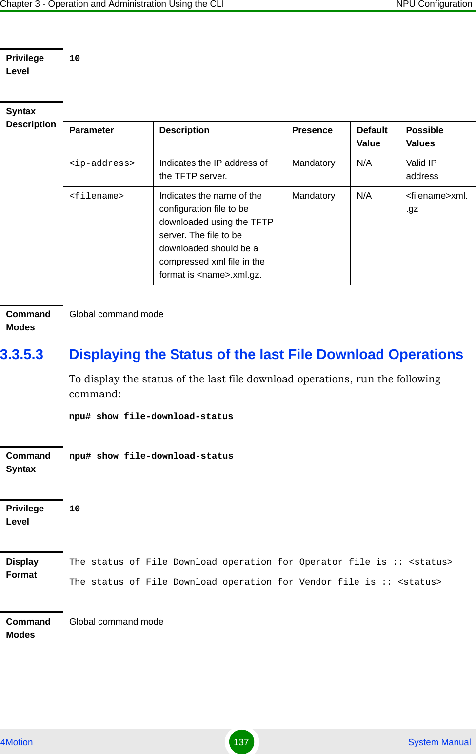
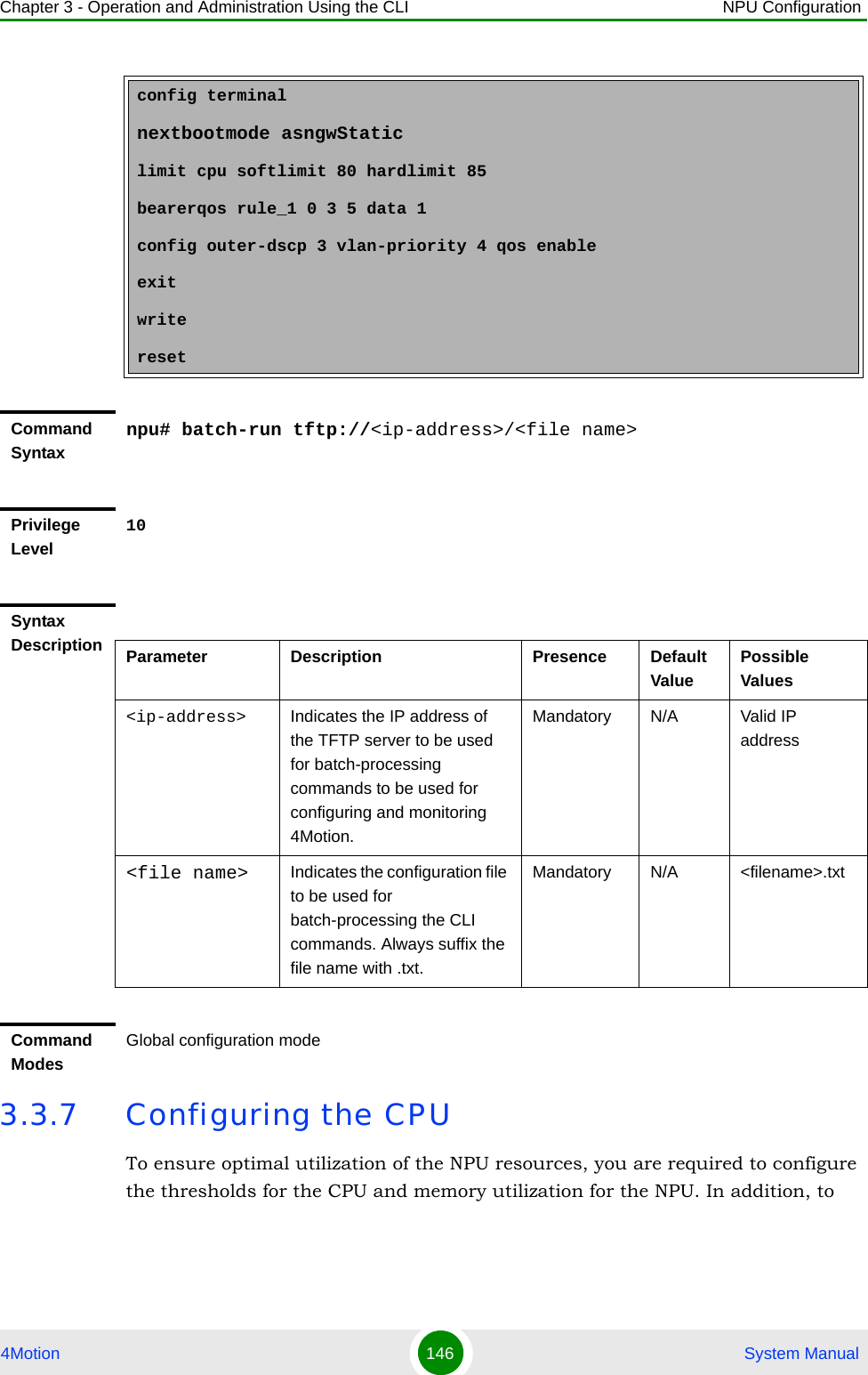
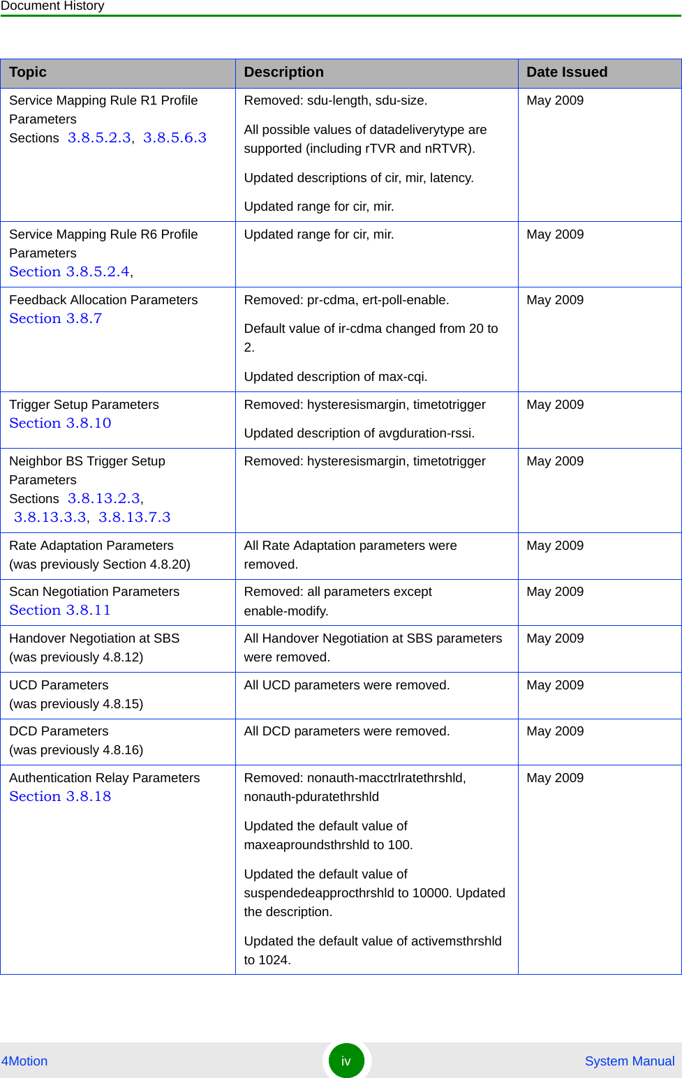
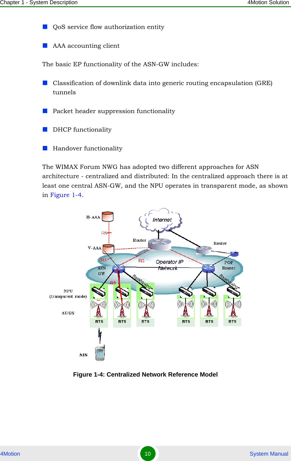
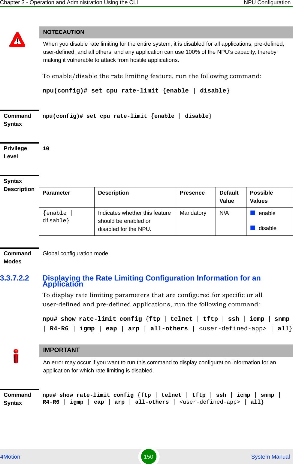
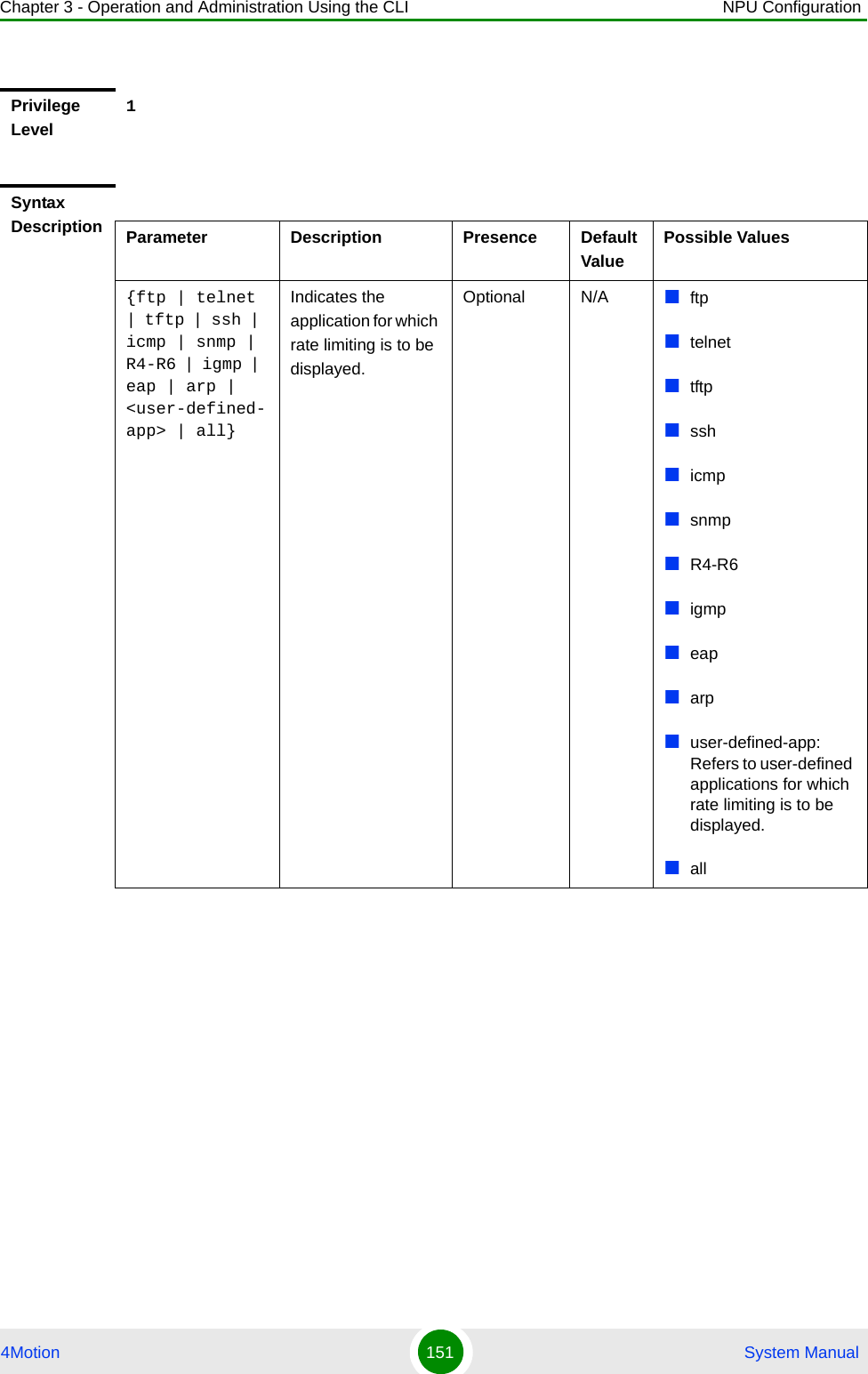
![Chapter 3 - Operation and Administration Using the CLI NPU Configuration4Motion 147 System Manualprotect the from hostile applications, the type and rate of traffic destined towards the NPU is limited by default. This section describes the commands to be executed for:“Configuring CPU and Memory Utilization Thresholds for the NPU” on page 147“Rate Limiting for the NPU” on page 1493.3.7.1 Configuring CPU and Memory Utilization Thresholds for the NPUThis section describes the commands for:“Specifying Thresholds for CPU and Memory Utilization for the NPU” on page 147“Displaying CPU and Memory Utilization Limits for the NPU” on page 1483.3.7.1.1 Specifying Thresholds for CPU and Memory Utilization for the NPUYou can use the CLI to configure the thresholds (soft and hard limits) for CPU and memory utilization for the NPU. When the soft or hard limit for either CPU or memory utilization is reached, an alarm is raised.To configure the thresholds (soft and hard limits) for CPU and memory utilization for the NPU, run the following command:npu(config)# limit {cpu | memory} ([softlimit <limit>] [hardlimit <limit>])For example, run the following command if you want to configure the soft and hard limits for CPU utilization to be 78 and 85 percent, respectively.npu(config)# limit cpu softlimit 80 hardlimit 85NOTETo display the current thresholds that are configured for CPU and memory utilization for the NPU, refer to Section 3.3.7.1.2.NOTEAn error may occur if the value of the softlimit parameter is higher than the hardlimit parameter.](https://usermanual.wiki/Alvarion-Technologies/BMAX-2-OR-25/User-Guide-1325752-Page-189.png)
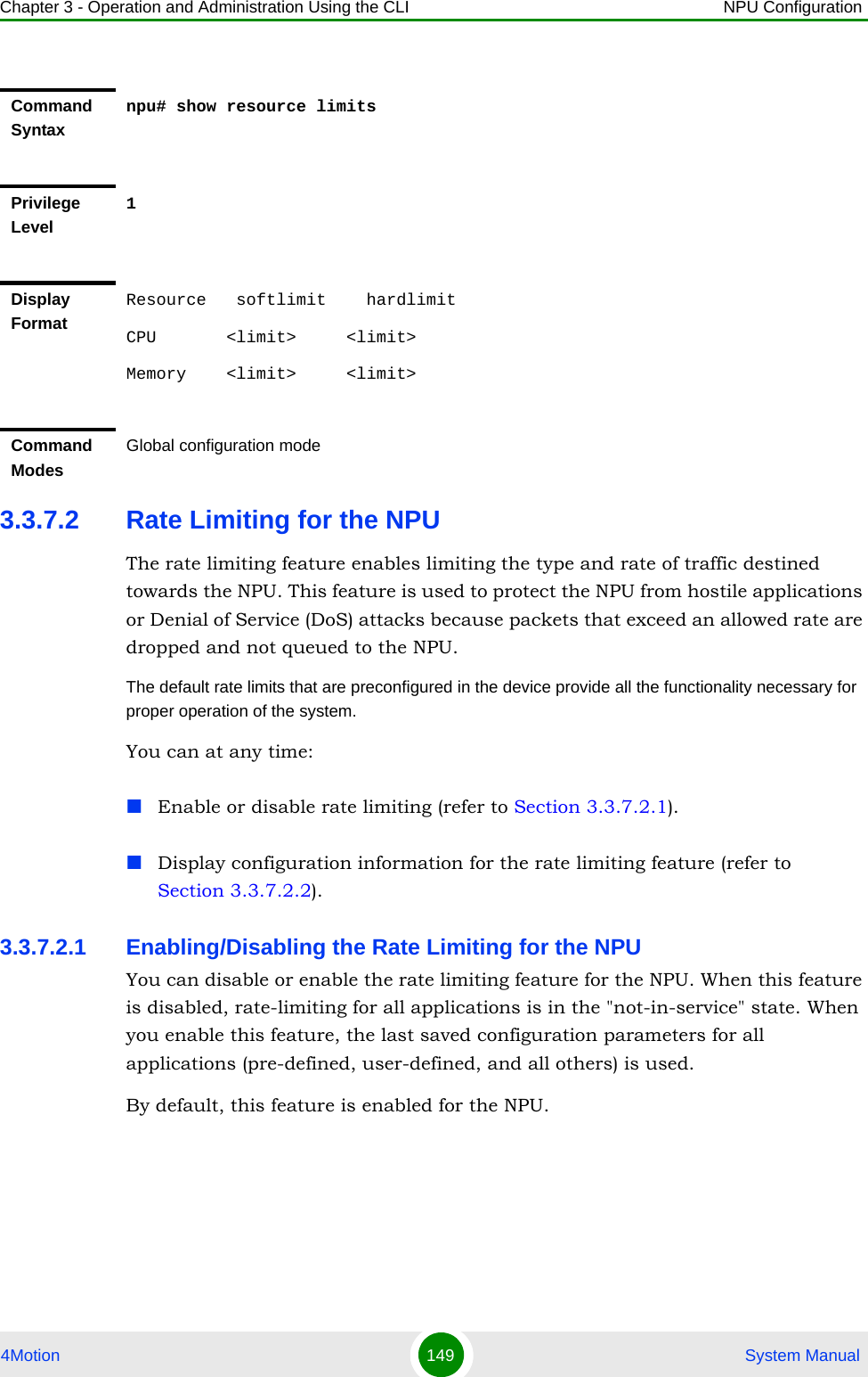
![Chapter 3 - Operation and Administration Using the CLI NPU Configuration4Motion 148 System Manual3.3.7.1.2 Displaying CPU and Memory Utilization Limits for the NPUTo display the configured CPU and memory utilization limits for the NPU, run the following command:npu# show resource limitsCommand Syntaxnpu(config)# limit {cpu | memory} ([softlimit <integer (1-99>] [hardlimit <integer (1-99>])Privilege Level10Syntax Description Parameter Description Presence Default ValuePossible Values{cpu | memory} Indicates whether the threshold is to be specified for CPU or memory utilization.Mandatory N/A cpu/ memory[softlimit <integer (1-99>]Indicates the soft limit, as a percentage, for CPU/memory utilization. When this limit is reached, the system raises a Minor or Major alarm.Optional 70 (for CPU and memory utilization)1-99[hardlimit <integer (1-99>])Indicates the hard limit, as a percentage, for CPU/memory utilization. When this limit is reached, the system raises a Critical alarm.The value of this parameter should always be greater than the softlimit parameter.Optional 90 (for CPU and memory utilization)1-99Command ModesGlobal configuration modeNOTETo configure the CPU and memory utilization limits for the NPU, refer to Section 3.3.7.1.2.](https://usermanual.wiki/Alvarion-Technologies/BMAX-2-OR-25/User-Guide-1325752-Page-190.png)
![Chapter 3 - Operation and Administration Using the CLI NPU Configuration4Motion 156 System Manualnpu(config-cmap)# set {[cos <new-cos(0-7)>] [ip dscp <new-dscp(0-63)>]}3.3.8.1.3 Deleting 802.1p and/or DSCP Values from a Class-mapRun the following command to delete the 802.1p VLAN priority and/or DSCP for this class-map.npu(config-cmap)# no {[cos <new-cos(0-7)>] [ip dscp <new-dscp(0-63)>]}Command Syntaxnpu(config-cmap)# set {[cos <new-cos(0-7)>] [ip dscp <new-dscp(0-63)>]}Privilege Level10Syntax Description Parameter Description Presence Default ValuePossible Values[cos <new-cos(0-7)>]Indicates the 802.1p VLAN priority value to be applied for this class-map.Optional N/A 0-7 where 0 is the lowest and 7 is the highest[ip dscp <new-dscp(0-63)>]Indicates the DSCP value to be applied for this class-map.Optional N/A 0-63Command ModesClass-map configuration modeIMPORTANTIf you are deleting the 802.1p VLAN priority and/or DSCP for a class-map that is associated with a QoS classification rule, first disable the QoS classification rules for that ACL. For details, refer to Section 3.3.8.3.IMPORTANTAn error may occur if the 802.1p or DSCP that you have specified do not exist for this class-map.Command Syntaxnpu(config-cmap)# no {[cos <new-cos(0-7)>] [ip dscp <new-dscp(0-63)>]}](https://usermanual.wiki/Alvarion-Technologies/BMAX-2-OR-25/User-Guide-1325752-Page-198.png)
![Chapter 3 - Operation and Administration Using the CLI NPU Configuration4Motion 157 System Manual3.3.8.1.4 Terminating the QoS Class-map Configuration ModeTo terminate the QoS class-map configuration mode, run the following command:npu(config-cmap)# exit3.3.8.1.5 Deleting a QoS Class-mapRun the following command to delete an existing QoS class-map:npu(config)# no class-map <class-map-number(1-65535)>Privilege Level10Syntax Description Parameter Description Presence Default ValuePossible Values[cos <new-cos(0-7)>]Indicates the 802.1p VLAN priority to be deleted for this class-map.Optional N/A 0-7[ip dscp <new-dscp(0-63)>]Indicates the DSCP to be deleted for this class-map.Optional N/A 0-63Command ModesQoS class-map configuration modeCommand Syntax npu(config-cmap)# exitPrivilege Level10Command ModesQoS class-map configuration modeIMPORTANTAn error may occur if you specify a class-map number that does not exist or is not within the range, 1-65535.](https://usermanual.wiki/Alvarion-Technologies/BMAX-2-OR-25/User-Guide-1325752-Page-199.png)
![Chapter 3 - Operation and Administration Using the CLI NPU Configuration4Motion 158 System Manual3.3.8.1.6 Displaying Configuration Information for a Class-mapRun the following command to view the configuration information for a class-map:npu# show class-map [<class-map-num(1-65535)>]Specify the class-map number if you want to view configuration information for a specific class-map. If you do not specify the class-map number, configuration information for all class-maps is displayed.Command Syntaxnpu(config)# no class-map <class-map-number(1-65535)>Privilege Level10Syntax Description Parameter Description Presence Default ValuePossible Values<class-map-number(1-65535)>Indicates the identifier of the QoS class-map number to be deleted.Mandatory N/A 1-65535Command ModesGlobal configuration modeIMPORTANTAn error may occur if you specify a class-map number that does not exist or is not within the range, 1-65535.Command Syntaxnpu# show class-map [<class-map-num(1-65535)>]Privilege Level1](https://usermanual.wiki/Alvarion-Technologies/BMAX-2-OR-25/User-Guide-1325752-Page-200.png)