Alvarion Technologies BMAX-2-OR-25 BreezeMAX 4Motion Broadband Wireless Access System User Manual 4Motion System Manual
Alvarion Technologies Ltd. BreezeMAX 4Motion Broadband Wireless Access System 4Motion System Manual
User Manual

4Motion®
System Manual
Release 2.5M2
April 2010
P/N 215637

Document History
4Motion ii System Manual
Document History
Topic Description Date Issued
Preliminary Release for Early Field
Trials
New System Manual January 2008
Preliminary Release for Beta May 2008
Release for GA July 2008
SDR
Section 1.3.1.3
Removed August 2008
Template Changed September 2008
Power Feeder
Section 1.3.4
Supported in release 2.5 December 2008
7 MHz Channel Bandwidth
Table 1-4, relevant sections in
Chapter 4.
Supported in release 2.5 December 2008
Installing 4x2 ODU
Section 2.1.4
Updated (including new installation options) December 2008
Installation recommendation
Section 2.3.9.1
Recommendation on installing AUs in a
3-sector configuration
December 2008
Trap Manager
Section 2.1.5
Modified instructions for initial configuration December 2008
Operation and Administration Using
the CLI
Chapter 4
Updated to reflect NPU SW Version 2_5_1_8 December 2008
Rate Limiting for the NPU
Section 3.3.7.2
Rate limits are configurable only by the
vendor.
May 2009
Configuring ACLs
Section 3.3.10
Updated default ACLs. May 2009
Configuring Performance Data
Collection
Section 3.3.13
Added support for new counters groups,
updated names.
May 2009
Configuring the Power Control
Required C/N Level Parameters
Section 3.8.6.2.2
Updated Defaults for cqi, cdma, qam64-1by2,
qam64-2by3, qam64-3by4, qam64-5by6.
May 2009
Managing the BS Keep-Alive
Functionality
Section 3.8.26
Updated commands’ syntax. May 2009
Managing the BS Idle Mode
Parameters
Section 3.8.28
New feature May 2009

Document History
4Motion iii System Manual
Managing BS Services
Section 3.8.4
Added new parameters: paging-cycle,
paging-offset, lm-traffic-idle-period,
dl-def-rate.
Updated range and default value for
max-subburst.
May 2009
Managing Ranging Parameters
Section 3.8.23
The following tables were removed from
operator CLI: Bandwidth Request, Handover
Ranging, Initial Ranging, Periodic Ranging,
Timing Correction.
contbased-rsrvtimeout was removed from
Ranging General table.
May 2009
Airframe General Parameters
Sections 3.8.16.2.1,
3.8.16.3.1, 3.8.16.5.1
Updated parameters:
Removed: enable-ul-scrotation.
Added: auto-diversity, auto-rx-enable.
Corrected name: ul-duration.
May 2009
Airframe Cyclic Delay Parameters
Section 3.8.16.2.4
Updated descriptions. May 2009
Airframe Linear Delay Parameters
Previousely Section 4.8.16.2.5
Updated descriptions. May 2009
Airframe Mapping Parameters
Previousely Section 4.8.16.2.6
Updated descriptions. May 2009
Airframe Receive Parameters
Previousely Section 4.8.16.2.7
Updated descriptions. May 2009
Airframe Downlink Diversity
Parameters
Section 3.8.16.2.3
Changed value range and default for the
mimo parameter.
May 2009
Airframe MIMO Parameters
Sections 3.8.16.2.8,
3.8.16.3.5, 3.8.16.5.8
New Airframe parameters table. May 2009
Neighbor BS General Parameters
Sections 3.8.13.2.1,
3.8.13.3.1, 3.8.13.7.1
Updated parameters:
Removed: restartcount
ucd-configchangecount and
dcd-configchangecount must be set to 0.
Added: paging-grp-id, nbr-strt-rng-codes.
Updated range and description: preamble-idx
May 2009
Topic Description Date Issued

Document History
4Motion iv System Manual
Service Mapping Rule R1 Profile
Parameters
Sections 3.8.5.2.3, 3.8.5.6.3
Removed: sdu-length, sdu-size.
All possible values of datadeliverytype are
supported (including rTVR and nRTVR).
Updated descriptions of cir, mir, latency.
Updated range for cir, mir.
May 2009
Service Mapping Rule R6 Profile
Parameters
Section 3.8.5.2.4,
Updated range for cir, mir. May 2009
Feedback Allocation Parameters
Section 3.8.7
Removed: pr-cdma, ert-poll-enable.
Default value of ir-cdma changed from 20 to
2.
Updated description of max-cqi.
May 2009
Trigger Setup Parameters
Section 3.8.10
Removed: hysteresismargin, timetotrigger
Updated description of avgduration-rssi.
May 2009
Neighbor BS Trigger Setup
Parameters
Sections 3.8.13.2.3,
3.8.13.3.3, 3.8.13.7.3
Removed: hysteresismargin, timetotrigger May 2009
Rate Adaptation Parameters
(was previously Section 4.8.20)
All Rate Adaptation parameters were
removed.
May 2009
Scan Negotiation Parameters
Section 3.8.11
Removed: all parameters except
enable-modify.
May 2009
Handover Negotiation at SBS
(was previously 4.8.12)
All Handover Negotiation at SBS parameters
were removed.
May 2009
UCD Parameters
(was previously 4.8.15)
All UCD parameters were removed. May 2009
DCD Parameters
(was previously 4.8.16)
All DCD parameters were removed. May 2009
Authentication Relay Parameters
Section 3.8.18
Removed: nonauth-macctrlratethrshld,
nonauth-pduratethrshld
Updated the default value of
maxeaproundsthrshld to 100.
Updated the default value of
suspendedeapprocthrshld to 10000. Updated
the description.
Updated the default value of activemsthrshld
to 1024.
May 2009
Topic Description Date Issued

Document History
4Motion v System Manual
Handover Control Parameters
Section 3.8.23
All configurable (read-write) parameters were
removed.
A new read-only parameter added:
CINRReuse.
May 2009
BS Management Alarm Thresholds
(was previously 4.8.26)
All BS Management Alarm Thresholds
parameters were removed.
May 2009
BS Alarm Threshold Parameters
Section 3.8.24
Removed: dl-droppedpackets, unalloc-slots,
dl-retransmissions, ul-retransmissions,
dl-subburstdrop, ul-subburstdrop.
Updated description, range and default for
ul-mednoise, ul-99prcntnoise.
Added: Be-exc-dl-drop-thr, rt-exc-dl-drop-thr,
nrt-exc-dl-drop-thr, ugs-exc-dl-drop-thr,
ert-exc-dl-drop-thr.
May 2009
Managing the Site General
Information
Section 3.3.15.7
Added section on displaying the site general
information.
Address parameter value was changed to up
to 70 characters.
Removed: AsnName, Region.
May 2009
Managing the Unique Identifier
Section 3.3.15.8
Added section on displaying the site ID. May 2009
Displaying the Vendor Identifier
Section 3.3.15.9
New feature. May 2009
AU Connectivity Parameters
Sections 3.5.2.3, 3.5.3.3,
3.5.6.3
Added new parameters: service-ip,
service-mask, service-next-hop.
Updatated possible values of bearervlanid
and the read-only
InternalManagementVLANID parameters.
May 2009
Configuring Physical and IP
Interfaces
Section 3.3.2
AU Fast Ethernet interfaces are not
configurable.
May 2009
Topic Description Date Issued

Document History
4Motion vi System Manual
AAA Client Configuration
Section 3.3.11.13.1
Updated with new parameters/commands and
additional changes related to support of
multiple AAA clients and AAA Redundancy.
In addition: Removed the auth-port and
acct-port parameters. Added command for
configuring the format of the Calling Station ID
MAC Address.
Added configuration rules for
primary-serveraddr and alternate-serveraddr.
Updated default and presence requirement
for primary-serveraddr.
Updated default and presence requirement
for rad-sharedsecret.
Updated description, default, possible values
and presence requirement for src-intf.
Added comment: If the bearer interface IP
address is being modified after aaa-client
configuration, you must re-configure the
src-intf parameter to "bearer" so that the
aaa-client will attach itself to the new bearer
interface IP address.
May 2009
Global RADIUS Parameters
Configuration
Section 3.3.11.13.2
Added: alrmAaaSwitchoverRetryFailThrshld May 2009
PIU HW Version
Section 3.3.15.1.2
Updated parameter’s possible values. May 2009
Displaying the Current Status of Shelf
Components
Section 3.10.1.2
Added description of displayed details. May 2009
Service Group
Section 3.3.11.14.1
srvc-grp (grp-alias) possible values changed
to 1-30 characters,
May 2009
Service Profile
Section 3.3.11.15.3.1
profile-name possible values changed to 1-30
characters,
May 2009
Classification Rules
Section 3.3.11.15.4.1
clsf-rule <rulename> possible values changed
to 1-30 characters,
May 2009
PHS Rules
Section 3.3.11.16.1
phs-rule <rulename> possible values
changed to 1-30 characters,
May 2009
Topic Description Date Issued

Document History
4Motion vii System Manual
Bearer Plane QoS Marking Rules
Section 3.3.11.11.1
qos-alias possible values changed to 1-30
characters,
media-type possible values changed to 1-30
characters,
May 2009
Log File Name
Section 3.3.12.1.5
file-name possible values changed to 1-50
characters,
May 2009
AU Maintenance VLAN ID
Section 3.3.3
New feature May 2009
AU Connectivity Parameters
Sections 3.5.2.3, 3.5.3.3,
3.5.6.3
Added service interface parameters. May 2009
Neighbor BS Triggers/Specific BS
Triggers
Sections 3.8.13.2.4,
3.8.13.7.5, 3.8.13.4
Added new table: Neighbor BS Specific BS
Triggers.
Updated-added details on deleting Neighbor
BS Triggers.
May 2009
Power Control Target Noise and
Interference Level Parameters
Sections 3.8.6.2.1, 3.8.6.3.1,
3.8.6.5.1
Added: power-control-correction-factor. May 2009
Managing Power Control Levels and
Policies
Section 3.8.6
The following tables were removed:
Open Loop Correction Policy,
Open Loop Correction Range,
Closed Loop - Unstable MS,
Closed Loop - MS in Network Entry,
Closed Loop Correction Range.
May 2009
GPS Position Parameters
Section 3.3.15.2.4
Added possible values details to Latitude and
Longitude.
May 2009
GPS General Configuration
Parameters
Sections 3.3.15.2.2, 3.3.15.2.7
Removed: AdaptorRequired May 2009
GPS Clock Mode
Was previously in sections
4.3.15.2.5, 4.3.15.2.11
Removed May 2009
Topic Description Date Issued

Document History
4Motion viii System Manual
AU Properties
Sections 3.5.2.1, 3.5.3.1,
3.5.6.1
Updated possible values for required-type.
Removed: required-ports, required-bandwidth
(and the corresponding InstalledPorts and
InstalledBandwidth).
Updated options for port-3 power and
port-4-power parameters (removed the NA
option).
May 2009
Sector Parameters
Section 3.9.1
heading is not mandatory when creating a
new sector. The default value is 0.
May 2009
Antennas
Section 3.7
heading is not mandatory when creating a
new antenna. Limitation related to antenna
heading vs. sector heading was removed).
Removed: gain, altitude, beamwidth,
electrical-azymuth-adjustment.
Added: antenna-product-id.
May 2009
BS Bearer Interface Parameters
Section 3.8.17
Added: bearer-vlan.
Updated possible values for
linkusage-hardthrshld.
May 2009
Managing MSs for Specific MS
Advanced Mode Data Collection
Section 3.8.27
New feature. May 2009
Handover Negotiation at TBS
Parameter
Section 3.8.12.1
The default value of defaultactiontime was
changed to 9.
May 2009
Power Control Maximum EIRP
Section 3.8.6.2.2
The default value for maxeirp was changed to
-99.
May 2009
Neighbor Advertisement Parameters
Section 3.8.8
Removed: mininterval-normalload,
mininterval-highload.
May 2009
IGMP Parameters
Section 3.3.11.2
Configurable only by the vendor. May 2009
MIP Foreign Agent Parameters
Section 3.3.11.3
Configurable only by the vendor. May 2009
Proxy-MIP Client Parameters
Section 3.3.11.4
Configurable only by the vendor. May 2009
ASN Interface Parameters
Section 3.3.11.5
Configurable only by the vendor. Updated
display format.
May 2009
Authenticator Function Parameters
Section 3.3.11.6
Configurable only by the vendor. Updated
display format.
May 2009
Topic Description Date Issued

Document History
4Motion ix System Manual
Data Path Function Parameters
Section 3.3.11.7
Configurable only by the vendor. Updated
display format.
May 2009
Context Function Parameters
Section 3.3.11.8
Configurable only by the vendor. Updated
display format.
May 2009
MS State Change Parameters
Section 3.3.11.9
Configurable only by the vendor. Updated
display format.
May 2009
Connectivity Service Network (CSN)
Parameters
Section 3.3.11.10
Configurable only by the vendor. Updated
display format.
May 2009
Enabling/Disabling VLAN Service
Interface
Section 3.3.11.14.3
Added default (disable). May 2009
Service Flows
Sections 3.3.11.15.3.3,
3.3.11.15.3.5
Removed: ulSfQosSduSize, dlSfQosSduSize.
Updated syntax of commands for better
support of commands auto-completion.
ul-unsol-intrvl not applicable for RTVR data
delivery type.
ulqos-trafficpriority and dlqos-trafficpriority not
applicable for UGS.
Updated range for ulqos-maxsustainedrate,
dlqos-maxsustainedrate, ul-rsrv-rate-min,
dl-rsrv-rate-min.
May 2009
Monitoring Software Components
Section 3.10.2
Removed details on counters-full and updated
information is provided in the Performance
Management document.
May 2009
Displaying Statistics for Physical and
IP Interfaces
Section 3.10.3
Removed details on counters-full and updated
information is provided in the Performance
Management document.
May 2009
System Log Files
Sections 3.3.12.1.5, 3.10.4
Corrected directory name to
tftpboot/management/system_logs (added s
at the end)
May 2009
Policy Framework
Section 3.3.11.17
New feature May 2009
Power Feeders Configuration
Section 3.3.15.3
pfAuSlotNoDestination,
pfAuPortNoDestination are optional.
May 2009
DHCP Server/Proxy Parameters
Sections 3.3.11.14.4.2,
3.3.11.14.4.3.
Added: Second DNS support (dnssrvr-addr2) May 2009
Topic Description Date Issued

Document History
4Motion x System Manual
Dry Contact Input Alarms
Sections 3.3.15.4, 3.3.15.6
Added alarmPolarity May 2009
Displaying the Active Clear Timer and
Event Rate Limit
Section 3.3.14.2.6
New command May 2009
ODUs
Sections 1.3.3, 2.1.3, 3.6.1.1,
3.6.1.2, 3.6.1.6, 3.6.2.
Tables 1-3, 1-7, 1-11, 1-21.
Added new ODUs:
ODU-HP-2.3-WCS,
ODU-2340-2400-000N-36-1X1-N-0,
ODU-2480-2690-000N-38-4X2-N-0.
Removed: 2x1 ODUs.
Updated the list of ODU types in CLI
(including types that are not available yet).
May 2009
ODU General Parameters
Sections 3.6.1.2, 3.6.1.3,
3.6.1.6.
Removed: heater-existence May 2009
Antennas
Table 1-35, Table 1-38
Added antennas:
ANT.2.3-2.7GHz, D/S,65°,16±0.5dBi,
ANT.3.5GHz, D/S,65°,16±0.5dBi
May 2009
Airframe Uplink Feedback Zone
Parameters
Section 3.8.16.2.4
Updated limitation for subchannels. May 2009
Service Mapping Rule R6 Profile
Parameters
Section 3.8.5.2.4
Updated range for mediaflowtype. May 2009
Configuring General Service Mapping
Rule Parameters
Section 3.8.5.2.1
Updated description of the srvc parameter. May 2009
Performance Data Collection
Section 3.3.13, Table 3-5
Updated syntax of commands for better
support of commands auto-completion.
May 2009
Configuring Common Parameters of
a Service Group
Section 3.3.11.14.2
Updated syntax of commands for better
support of commands auto-completion.
Updated description of dhcp-ownaddr.
May 2009
Enabling/Disabling VLAN Service
Interface
Section 3.3.11.14.3
Updated syntax of commands for better
support of commands auto-completion.
May 2009
Configuring the DHCP
Server/Proxy/Relay
Section 3.3.11.14.4
Updated syntax of commands for better
support of commands auto-completion.
May 2009
Topic Description Date Issued

Document History
4Motion xi System Manual
IP-IP Service Interface Parameters
Sections 3.3.11.12.2.1,
3.3.11.12.3.1
Updated syntax of commands for better
support of commands auto-completion.
May 2009
Displaying Configuration Information
for the Service Interface
Section 3.3.11.12.6
Updated May 2009
VLAN Service Interface Parameters
Sections 3.3.11.12.2.2,
3.3.11.12.3.2
Updated syntax of commands for better
support of commands auto-completion.
Updated possible values and description for
vlan-id.
Added mask for dflt-gw-ip.
May 2009
QinQ Service Interface Parameters
Section 3.3.11.12.2.3
Updated syntax of commands for better
support of commands auto-completion.
Updated possible values and description for
vlan-id.
May 2009
ASN-GW Keep-Alive Parameters
Section 3.3.11.17
Updated syntax of commands for better
support of commands auto-completion.
May 2009
Configuring Power Feeders
Section 3.3.15.3.1
Updated syntax of commands for better
support of commands auto-completion.
May 2009
RF Frequency
Section 3.8.14
Updated possible values. May 2009
General Neighbor BS Parameters
Section 3.8.13.2.1
Updated possible values. May 2009
Bearer Interface IP Address
Section 3.3.2.3.3
Addedd comment: After changing the bearer
IP address, save configuration and reboot to
apply changed IP address on ASN and CSN
interfaces.
May 2009
IP Connectivity Mode
Section 3.3.1.1
Added comment: You must save the
configuration for a change in connectivity
mode to take effect after next reset.
May 2009
Next Boot Mode
Section 3.3.4.1
Added comment: You must save the
configuration for a change in boot mode to
take effect after next reset.
May 2009
Restoring the Factory Default
Configuration With Connectivity
Section 3.3.5.4.7
New feature. May 2009
displaying Failures in Configuration
Restore Operations
Section 3.3.5.4.8
New feature. May 2009
Topic Description Date Issued

Document History
4Motion xii System Manual
Privilege Levels
Sections 3.1.5.5, 3.1.6
The highest privilege level available for users
is 10.
May 2009
DGW Profile
Sections 3.3.11.15.3.1,
3.3.11.15.3.3.1
Added a note (parameters related to DGW
profile are not applicable in current release).
May 2009
Power Feeders Requirements
Section 2.3.3.3
Required only in configurations with 6 AUs
where each AU is connected to 4 2.x GHz or
3.5 GHz 1x1 ODUs.
May 2009
Configuring the Properties of the
Physical Interface
Section 3.3.2.1.2
Physical interfaces can be configured when
the interface is enabled.
May 2009
Managing AUs
Section 3.5
Up to 6 AUs may be active (removed
limitation on number of AUs that can provide
services).
May 2009
Managing BSs
Section 3.8
Removed the requirement to explicitely
configure at least one parameter in tables with
no mandatory parameters.
May 2009
Apply command
Table 3-30, Sections 3.8.6,
3.8.20, 3.8.23.
Apply command not required for Power
Control Levels and Policies, Control Traffic
QoS Marking Rules and Ranging parameters,
unless none of the BS General parameters
was configured.
May 2009
BS Geneal Parameters
Section 3.8.3
Added ul-def-rate, dl-def-rate. May 2009
Commissioning-NPU Local
Connectivity-External Management
Interface
Section 2.1.3.3
No need to shut-down external interface
before configuring IP parameters.
May 2009
Commissioning-Completing the Site
Configuration Using
AlvariSTAR-Equipment
Configuration-AU
Section 2.2.4.1
Updated (only supported Type is AU 4x4
Modem, Ports and Bandwidth parameters
were removed).
May 2009
Commissioning-Completing the Site
Configuration Using
AlvariSTAR-Equipment-Antenna
Section 2.2.4.3
Updated: Added Antenna Product Type,
Number of Ports applicable only if Antenna
Product Type is set to Empty, Heading is not
mandatory.
May 2009
Topic Description Date Issued

Document History
4Motion xiii System Manual
Commissioning-Completing the Site
Configuration Using AlvariSTAR-BS
Configuration
Section 2.2.6
Removed the requirement for clicking Apply
on Radio Advanced screen and Connectivity
Advanced screen.
May 2009
Commissioning-Completing the Site
Configuration Using
AlvariSTAR-ASNGW Configuration
It is not mandartory to define AAA client (the
default client can be used).
May 2009
Creating a Sector Association Entry
Section 3.9.2.1
Updated association rules (relation between
antenna-type, auto-diversity and
auto-rx-enable parameters.
May 2009
Changes in Site Configuration
Section 2.1.3.4
Reset is required only for a change in
Connectivity Mode.
June 2009
Accessing the CLI from a Remote
Terminal
Section 3.1.2.2
No need to disable/enable the interface when
configuring an IP Address.
June 2009
Adding/Modifying Users
Section 3.1.6.1.1
Updated the command’s syntax. June 2009
Displaying the IP connectivity Mode
Section 3.3.1.2
Updated display format. June 2009
Managing VLAN Translation
Section 3.3.2.1.3
Updated ranges.
VLAN Translation entry can be created also
when VLAN Translation is disabled.
June 2009
Configuring IP Interfaces
Section 3.3.2.3
VLAN ID of Local Management Interface is
configurable.
It is not necessary to shut down an IP
interface for configuring its parameters.
June 2009
Configuring a QoS Classification Rule
Section 3.3.8.2.2
IP address of local-management can also be
used as host source IP address.
June 2009
Configuring Static Routes
Section 3.3.9
Added a note regarding automatically
added/deleted kernel routes.
June 2009
Configuring ACLs in the Standard
Mode
Section 3.3.10.1.2
Removed paragraph on Standard ACL 1
which was previously available by default.
June 2009
Configuring Permit/Deny Rules
from/to a Specific Protocol and
Source/Destination IP Addresses
Section 3.3.10.1.3.1
Any IANS value can be configured for the
protocol-type parameter, including IP, OSPF
and PIM.
June 2009
Topic Description Date Issued

Document History
4Motion xiv System Manual
Attaching/De-attaching ACLs to/from
an Interface
Section 3.3.10.3
Removed paragraph on Standard ACL 1
which was previously available by default.
June 2009
Enabling the Interface Configuration
Mode
Section 3.3.10.3.1
By default, all traffic destined towards the AUs
is denied and all traffic towards the NPU is
permitted.
June 2009
Deleting Next-hop IP
Address-Network ID Mappings
Section 3.3.11.1.2
nw-id parameter is optional. June 2009
Managing the Authenticator Function
Section 3.3.11.6
Updated descriptions for eapTimerTransfer
and eapCounterTransferMax.
June 2009
Managing the Data Path Function
Section 3.3.11.7
Updated descriptions of
dpTimerInitPathRegReq,
dpCounterInitPathRegReqMax,
dpTimerMsDeregReq,
dpCounterMsDeregReqMax,
dpTimerPathRegReq,
dpCounterPathRegReqMax,
dpTimerPathRegRsp,
dpCounterPathRegRspMax.
June 2009
Managing the Context Function
Section 3.3.11.8
Updated descriptions of all parameters. June 2009
Managing the MS State Change
Functionality
Section 3.3.11.9
Updated descriptions of
msscfnTimerMsscRsp,
msscfnCounterMsscRspMax,
msscfnTimerMsscDrctvReq,
msscfnCounterMsscDrctvReqMax.
June 2009
Configuring Bearer Plane QoS
Marking Rules
Section 3.3.11.11
Corrected value: Up to a maximum of 20
Bearer Plane QoS Marking Rules can be
defined.
June 2009
Deleting Bearer Plane QoS Marking
Rules
Section 3.3.11.11.5
"int_default" and "ext_default" Bearer Plane
QoS Marking Rules cannot be deleted.
June 2009
Enabling the Service Interface
Configuration Mode\Creating a
Service Interface
Section 3.3.11.12.1
Updated the value of the Service Interface
alias parameter (1-30 characters).
June 2009
Configuring Parameters for IP-IP
Service Interface
Section 3.3.11.12.2.1
srcaddr is mandatory. The only allowed value
is the Bearer IP Address.
dstaddr is mandatory.
Updated description of dstaddr.
June 2009
Topic Description Date Issued

Document History
4Motion xv System Manual
Configuring Parameters for VLAN
Service Interface
Section 3.3.11.12.2.2
vlan-id and dflt-gw-ip are mandatory. June 2009
Configuring Parameters for QinQ
Service Interface
Section 3.3.11.12.2.3
vlan-id is mandatory. June 2009
Configuring the AAA Client
Functionality
Section 3.3.11.13
rad-CallingStationId parameter added to AAA
Client parameters config command (instead
of config aaaserverMACFormat command
added in a previous version of this release).
June 2009
Restoring Operation with the Primary
Server
Section 3.3.11.13.1.2
Updated command syntax and description. June 2009
Deleting the AAA Client
Section 3.3.11.13.1.4
“default” client cannot be deleted. June 2009
Configuring DHCP Server
Parameters
Section 3.3.11.14.4.2.1
No need to delete service group for updating
pool-minaddr & pool-maxaddr values.
Corrected range for lease-interval
(24-4294967295).
Added rules for pool-minaddr &
pool-maxaddr.
Added rules for renew-interval.
June 2009
Deleting a Service Group
Section 3.3.11.14.9
To delete a VLAN type service group, first
execute the "no vlan-enable" command.
June 2009
Configuring Parameters for the Policy
Framework
Previousely Section 4.3.11.17.2
aaa-alias must be the alias of an active AAA
client.
June 2009
Managing the ASN-GW Keep-Alive
Functionality
Section 3.3.11.17
Updated description of the feature. June 2009
Configuring ASN-GW Keep-Alive
Parameters
Section 3.3.11.17.1
Added error condition.
Updated range and default for rtx-time.
June 2009
Configuring BS Keep-Alive
Parameters
Section 3.8.26.1
Added error condition. June 2009
Configuring the SNMP Manager
Section 3.3.14.1
Clarified that each SNMP Manager entry is
uniquely identified by the pair of values for the
Read Community and Write Community.
June 2009
Topic Description Date Issued

Document History
4Motion xvi System Manual
Configuring the Trap Manager
Section 3.3.14.2
Added note: A route to forward traps to a
configured Trap Manager IP address must
exist.
June 2009
Displaying the Trap Rate Limit
Section 3.3.14.2.5
Updated description. June 2009
Configuring the Date and Time
Section 3.3.15.2.3
Corrected the presence of UTC to Optional. June 2009
Configuring Power Feeders
Section 3.3.15.3.1
Added note on error condition. June 2009
Displaying the Unique Identifier for
the 4Motion Shelf
Section 3.3.15.8.2
Corrected command’s syntax. June 2009
Displaying the Vendor Identifier
Section 3.3.15.9
Updated description. June 2009
Displaying Location Information for
the 4Motion Shelf
This section (previously Section 4.10.1.4) was
removed (described in
Section 3.3.15.7.2).
June 2009
Displaying the Unique Identifier for
the 4Motion Shelf
This section (previously Section 4.10.1.5) was
removed (described in
Section 3.3.15.8.2).
June 2009
Enabling the Port Monitoring Session
Section 3.11.2.1
Updated command’s syntax. June 2009
Disabling a Port Monitoring Session
Section 3.11.2.1
Updated command’s syntax.
Updated description
June 2009
Upgrading the NPU: Step 2:
Triggering Software Download
Section B.2.1.2
Added error condition (available memory). June 2009
Upgrading the AU Step 3: Creating
the AU-to-Image Mapping
Section B.3.1.3
Removed error condition (regarding mapping
the AU to an image that is not residing in the
AU flash).
June 2009
Displaying the Card Types Installed in
Shelf Slots 1 - 9
Section 3.10.1.1
New June 2009
ODU Names
Table 1-7,
ODU-2340-2400-000N-36-1X1-N changed to
ODU-HP-2.3b
June 2009
Configuring Bearer Plane QoS
Marking Rules
Section 3.3.11.11
Updated description of the feature. June 2009
Topic Description Date Issued

Document History
4Motion xvii System Manual
Deleting Source Addresses
Section 3.3.11.15.4.5.5
Updated command syntax. June 2009
Deleting Destination Addresses
Section 3.3.11.15.4.6.5
Updated command syntax. June 2009
Enabling the Source Address
Configuration Mode\ Creating a New
Source Address
Section 3.3.11.15.4.5.1
Added Privilege Level definition. June 2009
Displaying the Status of the Manual
Backup Procedure
Section 3.3.5.4.2
Updated Privilege Level (10) June 2009
Displaying the Automatic Backup
Time
Section 3.3.5.4.4
Added to manual. June 2009
Displaying Failures in Configuration
Restore Operations
Section 3.3.5.4.8
Updated Privilege Level (10) June 2009
Displaying the Currently Stored
Backup Configuration Files
Section 3.3.5.4.9
Updated Privilege Level (10) June 2009
Displaying Configuration Information
for SNMP Managers
Section 3.3.14.1.3
Updated Privilege Level (10) June 2009
Displaying Configuration Information
for Trap Managers
Section 3.3.14.2.4
Updated Privilege Level (10) June 2009
Displaying Status Information for
HARQ Maximum Retransmissions
Parameter
(was previously section 4.8.30)
Removed. June 2009
Configuring Power Control Target
Noise and Interference Level
Parameters
Section 3.8.6.2.1
Updated default value of pusc to -127. June 2009
Specifying Configuration Parameters
for the L3 Classification Rule
Section 3.3.11.15.4.2
Added consistency and configuration rules for
iptos-low and iptos-high.
June 2009
Enabling the Source Port
Configuration Mode\ Creating a New
Source Port
Section 3.3.11.15.4.7.1
Added consistency rules for start-port and
end-port.
June 2009
Topic Description Date Issued

Document History
4Motion xviii System Manual
Enabling the Destination Port
Configuration Mode\ Creating a New
Destination Port
Section 3.3.11.15.4.8.1
Added consistency rules for start-port and
end-port.
June 2009
Enabling Protocol Lists
Section 3.3.11.15.4.4.2
Added consistency rules-impact of enabling
destination port range
June 2009
Enabling the Destination Port Range
Section 3.3.11.15.4.8.2
Added consistency rules-impact on
parameters of IP protocol lists
June 2009
Enabling the Destination Port Range
Section 3.3.11.15.4.7.2
Added consistency rules-impact on
parameters of IP protocol lists
June 2009
Configuring the Position
Section 3.3.15.2.4
Updated ranges for longitude and latitude. June 2009
Managing Handover Negotiation at
SBS Parameters
Section 3.8.12
The previously removed section was brought
back with one new parameter to support the
Blackout Period feature.
June 2009
Configuring the AAA Client
Functionality
Section 3.3.11.13
Removed all commands and parameters
associated with AAA server redundancy.
Only a single client (default) is supported.
June 2009
Configuring the Output Parameters
for Bearer Plane QoS Marking Rules
Section 3.3.11.11.2
Added a note-for VLAN Service Interface only
VLAN Priority marking is relevant.
June 2009
Managing Secure Shell (SSH)
Parameters
Section 3.1.7
New section June 2009
Using Miscellaneous Commands
Section 3.1.5.4
Update description of exit command. June 2009
Managing the Session
Section 3.1.8
New section June 2009
Topic Description Date Issued

Document History
4Motion xix System Manual
Managing Service Groups
Section 3.3.11.14
Added explanations on the different service
group types.
Added new type (VPWS-Mapped).
Added acctInterimTmr parameter and
updated range/default for acct parameter in IP
Service Group configuration.
Updated description for ms-loop.
Changed structure/headings and added new
sections for configuring VPWS service
groups.
Updated description of dhcp-ownaddr.
June 2009
Configuring Antenna Parameters
Section 3.7.2
Updated value range for latitude and
longitude, updated default for latitude.
June 2009
Macro Outdoor BTS
Sections 1.2.1, 1.3, 1.3.2 (new),
1.5.5, 1.5.6, 1.5.8, 1.5.9.7
(new), 1.5.9.8 (new), 1.5.9.9
(new), 2.4 (new). 3.1.1 (new)
New product line June 2009
Configuring the Site General
Information for the 4Motion Shelf
Section 3.3.15.7.1
Removed ProductType (not configurable) June 2009
Displaying the Site General
Information Parameters
Section 3.3.15.7.2
Product Type has several options. June 2009
Replacing a PIU
Section 2.3.10.4
Updated procedure June 2009
Output Alarms
Section 3.3.15.5.1
Corrected explanation of N.C. and N.O.
terms.
June 2009
Displaying the Currently Stored
Backup Configuration Files
Section 3.3.5.4.9
Added description of the file’s name format. June 2009
Restoring the Configuration Defined
in the Backup Configuration File
Section 3.3.5.4.5
Added description of the file’s name format. June 2009
Downloading a Configuration
File/Vendor Startup File from an
External Server
Section 3.3.5.2
Updated section, added info related to Vendor
Startup file and file name format.
June 2009
Topic Description Date Issued

Document History
4Motion xx System Manual
Displaying the Status of the last File
Download Operations
Section 3.3.5.3
New section June 2009
Configuring Service Parameters
Section 3.8.4.2
Updated range for paging-cycle, paging-offset
and lm-traffic-idle-period.
August 2008
4x2 ODU Installation Guidelines
Section 2.1.4.2
Updated August 2008
Configuring R6 Profile Parameters
Section 3.8.5.2.4
Updated value range for cir and mir
parameters.
August 2008
Configuring R1 Profile Parameters
Section 3.8.5.2.3
Updated value range for cir and mir
parameters.
August 2008
Specifying Service Flow
Configuration Parameters
Section 3.3.11.15.3.3.2
Updated value range for
ulqos-maxsustainedrate,
dlqos-maxsustainedrate, ul-rsrv-rate-min,
dl-rsrv-rate-min.
August 2008
Configuring Airframe MIMO
Parameters
Section 3.8.16.2.8
Updated default value of bcast-msgzone-loc. August 2008
Managing the Policy Framework
(was previously section 4.3.11.17)
Removed August 2008
Managing Handover Negotiation at
SBS
(was previously 4.8.12)
Removed August 2008
Configuring Alarm Threshold
Parameters
Section 3.8.24.1
Updated value range and defaul for
ul-mednoise and ul-99prcntnoise.
August 2008
Managing Service Interfaces
Section 3.3.11.12
Updated general description.
Removed QinQ Service Interface.
August 2008
Default login ID
Section 3.1
Changed from root to admin, with privilege
level 10.
August 2008
Configuring Service Flows
Section 3.3.11.15.3.3
Only IPv4CS service flows can be configured
in the device.
August 2008
Configuring ACLs
Section 3.3.10
Added details of modified ACL 1. August 2008
Configuring ODU Port Parameters
Section 3.6.2.2
Added warning - do not disable ODU ports August 2008
Configuring Airframe General
Parameters
Section 3.8.16.2.1
auto-diversity and auto-rx-enable are forced
to true (setting to false will be ignored).
August 2008
Topic Description Date Issued

Document History
4Motion xxi System Manual
Configuring Airframe Cyclic Delay
Parameters
Section 3.8.16.2.4
Updated dependencies. The values are set by
internal logic.
August 2008
Configuring Airframe Linear Delay
Parameters
Previousely Section 4.8.16.2.5
Updated dependencies. The values are set by
vendor file.
August 2008
Configuring Airframe Mapping
Parameters
Previousely Section 4.8.16.2.6
Updated dependencies. The values are set by
internal logic.
August 2008
Configuring Airframe Receive
Parameters
Previousely Section 4.8.16.2.7
The values are set by internal logic. August 2008
Configuring Antenna Parameters
Section 3.7.2
Updated possible values and default for
antenna-product-id.
August 2008
Configuring Airframe Uplink
Feedback Zone Parameters
Section 3.8.16.2.4
Value of subchannels is set internally
according to bandwidth.
August 2008
Configuring Airframe Downlink Data
Zone Parameters
Section 3.8.16.2.5
Value of subchannels is set internally
according to bandwidth.
August 2008
Configuring Airframe Uplink Data
Zone Parameters
Section 3.8.16.2.6
Value of subchannels-number is set internally
according to bandwidth.
startallocation is hard-coded (value=0).
August 2008
Configuring Airframe MIMO
Parameters
Section 3.8.16.2.8
bcast-msgzone-loc is hard coded (set to
nonSTCzoneOnly).
August 2008
Configuring Ranging Parameters
Section 3.8.23.2
Updated valid values for start-of-rng-codes. August 2008
Managing BS Feedback Allocation
Parameters
Section 3.8.7
Updated valid values for ir-cdma.
The value for max-cqi is set by vendor file.
Updated default value according to
bandwidth.
August 2008
Configuring Power Control Target
Noise and Interference Level
Parameters
Section 3.8.6.2.1
cqi-ack-ranging cannot be modified. August 2008
Configuring the Power Control
Maximum EIRP
Section 3.8.6.2.2
maxeirp cannot be modified. August 2008
Topic Description Date Issued

Document History
4Motion xxii System Manual
Configuring the Power Control
Required C/N Level Parameters
Section 3.8.6.2.2
All parameters cannot be modified. August 2008
Configuring Service Parameters
Section 3.8.4.2
max-subburst is not relevant.
trgt-err-rate cannot be modified.
August 2008
Configuring the Unique Identifier for
the 4Motion Shelf
Section 3.3.15.8.1
A change in site identifier will take effect after
reset.
Special procedure needed when changing the
site identifier of a device managed by
AlvariSTAR.
August 2008
Managing the IP Connectivity Mode
Section 3.3.1
Added AU maintenance IP domain.
Added note on VLAN operation mode of the
ports (tagged/untagged).
August 2008
Configuring Physical and IP
Interfaces
Section 3.3.2
Added AU maintenace IP domain. August 2008
Configuring Parameters for VLAN
Service Interface
Section 3.3.11.12.2.2
A Service Interface VLAN ID shall not conflict
also with AU Maintenance VLAN.
August 2008
Configuring BS Keep-Alive
Parameters
Section 3.8.26.1
Updated default values of tx-cnt and rtx-time. August 2008
Managing Scheduler Parameters
Section 3.8.29
New fearure August 2008
Configuring AU Connectivity
Section 3.5.2.3
Updated description of service-ip. August 2008
Chapter 2 - Installation Updated instruction for installing 4x2 ODUs
Updated instructions for installing GPS
Receiver.
Added Macro Outdoor BTS instalation
instructiond
August 2008
ODUs
Tables 1-3, 1-6 (new), 1-7,
1-11, 1-12 (new), 1-16 (new),
Section 3.6.1.1 (added note,
removed tables of currently available
ODUs)
Updated ODUs August 2008
Topic Description Date Issued

Document History
4Motion xxiii System Manual
Radio Standards
Section 1.5.7
Added FCC part 25 August 2008
Managing Service Interfaces
Section 3.3.11.12
QinQ Service Interface is supported (for
special needs)
August 2008
Configuring Service Profiles
Section 3.3.11.15.3
VLAN CS Service Flows can be configured for
the Default Service Profile
August 2008
1x1 ODU LEDs
Table 2-3
ETH connector is functional August 2008
Configuring General Neighbor BS
Parameters
Section 3.8.13.2.1
Updated range for frequency August 2008
Configuring the RF Frequency
Parameter
Section 3.8.14.1
Updated range for frequency August 2008
Configuring Bearer Traffic QoS
Marking Rule Parameters
Section 3.8.20.2
Updated range for srvcflow-datadeliverytype. August 2008
Configuring/Modifying the VLAN ID
for an IP Interface
Section 3.3.2.3.5
Added note that after changing the bearer
interface VLAN ID the bearervlanid of all AUs
must be changed to the same value.
August 2008
Restoring the Factory Default
Configuration
Section 3.3.5.4.6
Added note-reset required. August 2008
Restoring the Factory Default
Configuration With Connectivity
Section 3.3.5.4.7
Added note-reset required. August 2008
Deleting Service Flows
Section 3.3.11.15.3.3.7
Corrected range for flow-id August 2008
Configuring ASN-GW Keep-Alive
Parameters
Section 3.3.11.17.1
Corrected command syntax August 2008
Configuring Logging
Section 3.3.12
Added note: Logging configuration reverts to
default after NPU reset.
August 2008
Managing the BS Idle Mode
Parameters
Section 3.8.28
Updated description of the feature. August 2008
IF Cables
Tables 2-1, 2-2
Limitations/Max Length for 3.5 GHz units are
the same as for other ODUs
August 2008
Topic Description Date Issued

Document History
4Motion xxiv System Manual
Commissioning
Section 2.1
No need to configure ACL August 2008
Configuring Airftame Parameters
Section 3.8.16.2
Removed sections related to Cyclic Delay
Parameters, Linear Delay Parameters,
Mapping Parameters and Receive
Parameters. In General Parameters,
auto-diversity and auto-rx-enable were
removed.
Added notes regarding parameters that are
not relevant (ignored) in Uplink Feedback
Zone Parameters, Downlink Data Zone
Parameters, Uplink Data Zone Parameters,
MIMO Parameters.
August 2008
Restoring Default Values for Airframe
Parameters
Section 3.8.16.3
Removed sections related to Cyclic Delay
Parameters, Linear Delay Parameters,
Mapping Parameters, Receive Parameters
and Uplink Data Zone Parameters. In General
Parameters, auto-diversity and auto-rx-enable
were removed. Added a note that the
command for restoring the default values for
Uplink Data Zone parameters is not
applicable for the current release.
Added notes regarding parameters that are
not relevant (ignored) in MIMO Parameters.
August 2008
Displaying Configuration Information
for Airftame Parameters
Section 3.8.16.5
Removed sections related to Cyclic Delay
Parameters, Linear Delay Parameters,
Mapping Parameters and Receive
Parameters.
August 2008
Managing BS Feedback Allocation
Parameters
Section 3.8.7
Added a note related to max-cqi parameter
that cannot be modified.
August 2008
Configuring Power Control Target
Noise and Interference Level
Parameters
Section 3.8.6.2.1
Added a note related to cqi-ack-ranging
parameter that cannot be modified.
August 2008
Restoring the Default Values of
Power Control Target Noise and
Interference Level Parameters
Section 3.8.6.3.1
Added a note related to cqi-ack-ranging
parameter that cannot be restored to default
value.
August 2008
Topic Description Date Issued

Document History
4Motion xxv System Manual
Managing Power Control Levels
Section 3.8.6
Removed sections related to configuring or
restoring the default value of Maximum
EIRxP. Added a note that this command is not
applicable for the current release. Updated
the description for displaying configuration
values of the parameter.
Added a note regarding nilevels
cqi-ack-ranging parameter that cannot be
modified.
Required C/N Levels are configurable.
Updated default value for Required C/N
Levels: ack, cqi, cdma.
August 2008
Configuring BS Service Parameters
Section 3.8.4.2
Added a note regarding parameters that are
not relevant or cannot be modified.
August 2008
Restoring Default Values for BS
Service Parameters
Section 3.8.4.3
Added a note regarding parameters that are
not relevant or cannot be modified.
August 2008
Managing AUs
Section 3.5
Removed sections related to configuring,
restoring default values and displaying
configured values of reserved parameters.
Added a not that these commands are not
applicable for current release.
September 2009
Configuring ODUs
Section 3.6.1
Removed sections related to configuring,
restoring default values and displaying
configured values of reserved parameters.
Added a not that these commands are not
applicable for current release.
September 2009
Managing BS Reserved Parameters
Section 3.8.25
Removed sections related to configuring,
restoring default values and displaying
configured values of reserved parameters.
Added a not that these commands are not
applicable for current release.
September 2009
Managing the IGMP Functionality
Section 3.3.11.2
Removed details, added a note that relevant
show commands are not applicable since the
feature is not supported in the current release.
September 2009
Managing the MIP-Foreign Agent
Functionality
Section 3.3.11.3
Removed details, added a note that relevant
show command is not applicable since the
feature is not supported in the current release.
September 2009
Managing the Proxy-MIP Client
Functionality
Section 3.3.11.4
Removed details, added a note that relevant
show command is not applicable since the
feature is not supported in the current release.
September 2009
Topic Description Date Issued

Document History
4Motion xxvi System Manual
Configuring the 4Motion Shelf
Section 3.3.15
Updated descriptions of components. September 2009
Configuring Bearer Plane QoS
Marking Rules
Section 3.3.11.11
Updated general description September 2009
Configuring Power Control Target
Noise and Interference Level
Parameters
Section 3.8.6.2.1
Updated range for pusc. September 2009
AUs
Section 3.1.1.6
Changed the mapping of the Macro Outdoor
BTS AUs to Slot
January 2010
Sun Guard Installation
Section 2.1.4.7
Updated: 4x2 ODUs and also NAU, DAU, and
SAU units of the Macro Outdoor BTS may
come with a sun-guard pre-installed
January 2010
Chapter 2 - Installation Removed from the manual. Refer to the
detailed Installation Manual
April 2010
Macro Outdoor Units
Section 1.3.2, Section 3.5
New unit types with 2-channels AUs. April 2010
2x2 ODUs
Sections 1.3.3, 1.5.3.2.2,
1.5.3.3.2, 1.5.3.5.2
New ODU types April 2010
Topic Description Date Issued

Legal Rights
4Motion xxvii System Manual
Legal Rights
© Copyright 2010 Alvarion Ltd. All rights reserved.
The material contained herein is proprietary, privileged, and confidential and
owned by Alvarion or its third party licensors. No disclosure thereof shall be made
to third parties without the express written permission of Alvarion Ltd.
Alvarion Ltd. reserves the right to alter the equipment specifications and
descriptions in this publication without prior notice. No part of this publication
shall be deemed to be part of any contract or warranty unless specifically
incorporated by reference into such contract or warranty.
Trade Names
Alvarion®, BreezeCOM®, WALKair®, WALKnet®, BreezeNET®, BreezeACCESS®,
BreezeLINK®, BreezeMAX®, BreezeLITE®, BreezePHONE®, 4Motion®, and/or other
products and/or services referenced here in are either registered trademarks,
trademarks or service marks of Alvarion Ltd.
All other names are or may be the trademarks of their respective owners.
“WiMAX Forum” is a registered trademark of the WiMAX Forum. “WiMAX,” the
WiMAX Forum logo, “WiMAX Forum Certified”, and the WiMAX Forum Certified
logo are trademarks of the WiMAX Forum.
Statement of Conditions
The information contained in this manual is subject to change without notice.
Alvarion Ltd. shall not be liable for errors contained herein or for incidental or
consequential damages in connection with the furnishing, performance, or use of
this manual or equipment supplied with it.
Warranties and Disclaimers
All Alvarion Ltd. (“Alvarion“) products purchased from Alvarion or through any of
Alvarion's authorized resellers are subject to the following warranty and product
liability terms and conditions.
Exclusive Warranty
(a) Alvarion warrants that the Product hardware it supplies and the tangible
media on which any software is installed, under normal use and conditions, will
be free from significant defects in materials and workmanship for a period of
fourteen (14) months from the date of shipment of a given Product to Purchaser
(the "Warranty Period"). Alvarion will, at its sole option and as Purchaser's sole
remedy, repair or replace any defective Product in accordance with Alvarion'
standard R&R procedure.

Legal Rights
4Motion xxviii System Manual
(b) With respect to the Firmware, Alvarion warrants the correct functionality
according to the attached documentation, for a period of fourteen (14) month from
invoice date (the "Warranty Period")". During the Warranty Period, Alvarion may
release to its Customers firmware updates, which include additional performance
improvements and/or bug fixes, upon availability (the "Warranty"). Bug fixes,
temporary patches and/or workarounds may be supplied as Firmware updates.
Additional hardware, if required, to install or use Firmware updates must be
purchased by the Customer. Alvarion will be obligated to support solely the two (2)
most recent Software major releases.
ALVARION SHALL NOT BE LIABLE UNDER THIS WARRANTY IF ITS TESTING
AND EXAMINATION DISCLOSE THAT THE ALLEGED DEFECT IN THE PRODUCT
DOES NOT EXIST OR WAS CAUSED BY PURCHASER'S OR ANY THIRD
PERSON'S MISUSE, NEGLIGENCE, IMPROPER INSTALLATION OR IMPROPER
TESTING, UNAUTHORIZED ATTEMPTS TO REPAIR, OR ANY OTHER CAUSE
BEYOND THE RANGE OF THE INTENDED USE, OR BY ACCIDENT, FIRE,
LIGHTNING OR OTHER HAZARD.
Disclaimer
(a) The Software is sold on an "AS IS" basis. Alvarion, its affiliates or its licensors
MAKE NO WARRANTIES, WHATSOEVER, WHETHER EXPRESS OR IMPLIED,
WITH RESPECT TO THE SOFTWARE AND THE ACCOMPANYING
DOCUMENTATION. ALVARION SPECIFICALLY DISCLAIMS ALL IMPLIED
WARRANTIES OF MERCHANTABILITY AND FITNESS FOR A PARTICULAR
PURPOSE AND NON-INFRINGEMENT WITH RESPECT TO THE SOFTWARE.
UNITS OF PRODUCT (INCLUDING ALL THE SOFTWARE) DELIVERED TO
PURCHASER HEREUNDER ARE NOT FAULT-TOLERANT AND ARE NOT
DESIGNED, MANUFACTURED OR INTENDED FOR USE OR RESALE IN
APPLICATIONS WHERE THE FAILURE, MALFUNCTION OR INACCURACY OF
PRODUCTS CARRIES A RISK OF DEATH OR BODILY INJURY OR SEVERE
PHYSICAL OR ENVIRONMENTAL DAMAGE ("HIGH RISK ACTIVITIES"). HIGH
RISK ACTIVITIES MAY INCLUDE, BUT ARE NOT LIMITED TO, USE AS PART OF
ON-LINE CONTROL SYSTEMS IN HAZARDOUS ENVIRONMENTS REQUIRING
FAIL-SAFE PERFORMANCE, SUCH AS IN THE OPERATION OF NUCLEAR
FACILITIES, AIRCRAFT NAVIGATION OR COMMUNICATION SYSTEMS, AIR
TRAFFIC CONTROL, LIFE SUPPORT MACHINES, WEAPONS SYSTEMS OR
OTHER APPLICATIONS REPRESENTING A SIMILAR DEGREE OF POTENTIAL
HAZARD. ALVARION SPECIFICALLY DISCLAIMS ANY EXPRESS OR IMPLIED
WARRANTY OF FITNESS FOR HIGH RISK ACTIVITIES.
(b) PURCHASER'S SOLE REMEDY FOR BREACH OF THE EXPRESS
WARRANTIES ABOVE SHALL BE REPLACEMENT OR REFUND OF THE
PURCHASE PRICE AS SPECIFIED ABOVE, AT ALVARION'S OPTION. TO THE

Legal Rights
4Motion xxix System Manual
FULLEST EXTENT ALLOWED BY LAW, THE WARRANTIES AND REMEDIES SET
FORTH IN THIS AGREEMENT ARE EXCLUSIVE AND IN LIEU OF ALL OTHER
WARRANTIES OR CONDITIONS, EXPRESS OR IMPLIED, EITHER IN FACT OR BY
OPERATION OF LAW, STATUTORY OR OTHERWISE, INCLUDING BUT NOT
LIMITED TO WARRANTIES, TERMS OR CONDITIONS OF MERCHANTABILITY,
FITNESS FOR A PARTICULAR PURPOSE, SATISFACTORY QUALITY,
CORRESPONDENCE WITH DESCRIPTION, NON-INFRINGEMENT, AND
ACCURACY OF INFORMATION GENERATED. ALL OF WHICH ARE EXPRESSLY
DISCLAIMED. ALVARION' WARRANTIES HEREIN RUN ONLY TO PURCHASER,
AND ARE NOT EXTENDED TO ANY THIRD PARTIES. ALVARION NEITHER
ASSUMES NOR AUTHORIZES ANY OTHER PERSON TO ASSUME FOR IT ANY
OTHER LIABILITY IN CONNECTION WITH THE SALE, INSTALLATION,
MAINTENANCE OR USE OF ITS PRODUCTS.
Limitation of Liability
(a) ALVARION SHALL NOT BE LIABLE TO THE PURCHASER OR TO ANY THIRD
PARTY, FOR ANY LOSS OF PROFITS, LOSS OF USE, INTERRUPTION OF
BUSINESS OR FOR ANY INDIRECT, SPECIAL, INCIDENTAL, PUNITIVE OR
CONSEQUENTIAL DAMAGES OF ANY KIND, WHETHER ARISING UNDER
BREACH OF CONTRACT, TORT (INCLUDING NEGLIGENCE), STRICT LIABILITY
OR OTHERWISE AND WHETHER BASED ON THIS AGREEMENT OR
OTHERWISE, EVEN IF ADVISED OF THE POSSIBILITY OF SUCH DAMAGES.
(b) TO THE EXTENT PERMITTED BY APPLICABLE LAW, IN NO EVENT SHALL
THE LIABILITY FOR DAMAGES HEREUNDER OF ALVARION OR ITS EMPLOYEES
OR AGENTS EXCEED THE PURCHASE PRICE PAID FOR THE PRODUCT BY
PURCHASER, NOR SHALL THE AGGREGATE LIABILITY FOR DAMAGES TO ALL
PARTIES REGARDING ANY PRODUCT EXCEED THE PURCHASE PRICE PAID
FOR THAT PRODUCT BY THAT PARTY (EXCEPT IN THE CASE OF A BREACH OF
A PARTY'S CONFIDENTIALITY OBLIGATIONS).
Radio Frequency Interference Statement
The Base Transceiver Station (BTS) equipment has been tested and found to
comply with the limits for a class A digital device, pursuant to ETSI EN 301 489-1
rules and Part 15 of the FCC Rules. These limits are designed to provide
reasonable protection against harmful interference when the equipment is
operated in commercial, business and industrial environments. This equipment
generates, uses, and can radiate radio frequency energy and, if not installed and
used in accordance with the instruction manual, may cause harmful interference
to radio communications. Operation of this equipment in a residential area is
likely to cause harmful interference in which case the user will be required to
correct the interference at the user's own expense.

Legal Rights
4Motion xxx System Manual
FCC Radiation Hazard Warning
To comply with FCC RF exposure requirements in Section 1.1307 and 2.1091 of
FCC Rules, the antenna used for this transmitter must be fixed-mounted on
outdoor permanent structures with a separation distance of at least 2 meter from
all persons.
R&TTE Compliance Statement
This equipment complies with the appropriate essential requirements of Article 3
of the R&TTE Directive 1999/5/EC.
Safety Considerations - General
For the following safety considerations, "Instrument" means the BreezeMAX units'
components and their cables.
Grounding
BTS chassis, Power Feeders and Outdoor Units are required to be bonded to
protective grounding using the bonding stud or screw provided with each unit.
Safety Considerations - DC Powered Equipment (BTS & Power Feeder)
Restricted Access Area: The DC powered equipment should only be installed in a
Restricted Access Area.
Installation Codes: The equipment must be installed according to the latest
edition of the country national electrical codes. For North America, equipment
must be installed in accordance with the US National Electrical Code and the
Canadian Electrical Code.
Overcurrent Protection: A readily accessible Listed branch circuit overcurrent
protective device, rated 60A for the BTS or 20A for the Power Feeder, must be
incorporated in the building wiring.
CAUTION: This equipment is designed to permit connection between the earthed
conductor of the DC supply circuit and the grounding conductor at the
equipment. See installation instructions.
CAUTION ATTENTION
Risk of electric shock and energy
hazard.Disconnecting one Power Interface Unit
(PIU) disconnects only one PIU module. To
isolate the BTS completely, disconnect both
PIUs
Risque de décharge électrique et
d'electrocution. La déconnection d'un seul
module d'alimentation (PIU) n'isole pas
complètement la Station de Base. Pour cela, il
faut impérativement débrancher les deux
modules d'alimentation (PIU).

Legal Rights
4Motion xxxi System Manual
The equipment must be connected directly to the DC Supply System
grounding electrode conductor.
All equipment in the immediate vicinity must be grounded in the same way,
and not be grounded elsewhere.
The DC supply system is to be local, i.e. within the same premises as the
equipment.
There shall be no disconnect device between the grounded circuit conductor of
the DC source (return) and the point of connection of the grounding electrode
conductor.
Lithium Battery
The battery on the NPU card is not intended for replacement.
Caution
To avoid electrical shock, do not perform any servicing unless you are qualified to
do so.
Line Voltage
Before connecting this instrument to the power line, make sure that the voltage of
the power source matches the requirements of the instrument.
Radio
The instrument transmits radio energy during normal operation. To avoid possible
harmful exposure to this energy, do not stand or work for extended periods of time
in front of its antenna. The long-term characteristics or the possible physiological
effects of radio frequency electromagnetic fields have not been yet fully
investigated.
Outdoor Units and Antennas Installation and Grounding
Ensure that outdoor units, antennas and supporting structures are properly
installed to eliminate any physical hazard to either people or property. Make sure
that the installation of the outdoor unit, antenna and cables is performed in
accordance with all relevant national and local building and safety codes. Even
where grounding is not mandatory according to applicable regulation and national
codes, it is highly recommended to ensure that the outdoor unit and the antenna
mast (when using external antenna) are grounded and suitable lightning
protection devices are used so as to provide protection against voltage surges and
static charges. In any event, Alvarion is not liable for any injury, damage or

Legal Rights
4Motion xxxii System Manual
regulation violations associated with or caused by installation, grounding or
lightning protection.
Disposal of Electronic and Electrical Waste
Disposal of Electronic and Electrical Waste
Pursuant to the WEEE EU Directive electronic and electrical waste must not be disposed of with
unsorted waste. Please contact your local recycling authority for disposal of this product.

Important Notice
4Motion xxxiii System Manual
Important Notice
This user manual is delivered subject to the following conditions and restrictions:
This manual contains proprietary information belonging to Alvarion Ltd. Such
information is supplied solely for the purpose of assisting properly authorized
users of the respective Alvarion products.
No part of its contents may be used for any other purpose, disclosed to any
person or firm or reproduced by any means, electronic and mechanical,
without the express prior written permission of Alvarion Ltd.
The text and graphics are for the purpose of illustration and reference only.
The specifications on which they are based are subject to change without
notice.
The software described in this document is furnished under a license. The
software may be used or copied only in accordance with the terms of that
license.
Information in this document is subject to change without notice. Corporate
and individual names and data used in examples herein are fictitious unless
otherwise noted.
Alvarion Ltd. reserves the right to alter the equipment specifications and
descriptions in this publication without prior notice. No part of this
publication shall be deemed to be part of any contract or warranty unless
specifically incorporated by reference into such contract or warranty.
The information contained herein is merely descriptive in nature, and does not
constitute an offer for the sale of the product described herein.
Any changes or modifications of equipment, including opening of the
equipment not expressly approved by Alvarion Ltd. will void equipment
warranty and any repair thereafter shall be charged for. It could also void the
user's authority to operate the equipment.
Some of the equipment provided by Alvarion and specified in this manual, is
manufactured and warranted by third parties. All such equipment must be
installed and handled in full compliance with the instructions provided by such
manufacturers as attached to this manual or provided thereafter by Alvarion or
the manufacturers. Non-compliance with such instructions may result in serious

Important Notice
4Motion xxxiv System Manual
damage and/or bodily harm and/or void the user's authority to operate the
equipment and/or revoke the warranty provided by such manufacturer.

About This Manual
4Motion xxxv System Manual
About This Manual
This manual describes the 4Motion solution, and details how to install, operate
and manage the BTS system components.
This manual is intended for technicians responsible for installing, setting and
operating the 4Motion BTS equipment, and for system administrators responsible
for managing the system.
This manual contains the following chapters and appendices:
Chapter 1 - System description: Describes the 4Motion BTS and its
components.
Chapter 2 - Installation: Describes how to install the BTS components.
Chapter 3 - Commissioning: Describes how to configure basic parameters
and validate units' operation.
Chapter 4 - Operation and Administration Using the CLI: Describes how to
use the Command Line Interface (CLI) for configuring parameters, checking
system status and monitoring performance.
Appendix A - Antenna Configurations: Describes the proposed antenna
configurations that support the different available diversity scenarios.
Appendix B - Software Upgrade: Describes how to load new software files
using TFTP, and how to switch to a new software version in 4Motion units.
Glossary: A listing of commonly used terms.

Contents
4Motion xxxvi System Manual
Contents
Chapter 1 - System Description
1.1 About WiMAX................................................................................................................3
1.2 4Motion Solution ..........................................................................................................4
1.2.1 4Motion Solution Highlights.................................................................................4
1.2.2 WiMAX Network Reference Model......................................................................6
1.3 The Base Transceiver Station...................................................................................13
1.3.1 The Indoor Macro BTS......................................................................................14
1.3.2 The Macro Outdoor BTS...................................................................................20
1.3.3 ODU ..................................................................................................................21
1.3.4 Power Feeder....................................................................................................22
1.3.5 Antenna.............................................................................................................22
1.3.6 GPS...................................................................................................................23
1.4 Element Management Systems.................................................................................24
1.4.1 AlvariSTAR........................................................................................................24
1.5 Specifications.............................................................................................................26
1.5.1 Modem & Radio ................................................................................................26
1.5.2 Sensitivity..........................................................................................................26
1.5.3 ODUs ................................................................................................................27
1.5.4 AU - ODU Communication................................................................................38
1.5.5 Data Communication (Ethernet Interfaces).......................................................38
1.5.6 Configuration and Management........................................................................39
1.5.7 Standards Compliance, General.......................................................................40
1.5.8 Environmental ...................................................................................................40

Contents
4Motion xxxvii System Manual
1.5.9 Mechanical and Electrical .................................................................................41
1.5.10 Antennas...........................................................................................................46
Chapter 2 - Commissioning
2.1 Initial NPU Configuration...........................................................................................54
2.1.1 Introduction .......................................................................................................54
2.1.2 NPU Local Connectivity ....................................................................................54
2.1.3 Site Connectivity ...............................................................................................54
2.1.4 Static Route Definition.......................................................................................56
2.1.5 SNMP Manager Definition.................................................................................56
2.1.6 Mapping the AU Software Version....................................................................57
2.1.7 Site ID Definition ...............................................................................................57
2.1.8 Saving the Configuration...................................................................................57
2.2 Completing the Site Configuration Using AlvariSTAR ...........................................58
2.2.1 Introduction .......................................................................................................58
2.2.2 Site Configuration..............................................................................................59
2.2.3 Connectivity Configuration (optional) ................................................................59
2.2.4 Equipment Configuration...................................................................................59
2.2.5 ASNGW Configuration ......................................................................................61
2.2.6 BS Configuration...............................................................................................63
2.2.7 Site Sector Configuration ..................................................................................64
2.2.8 Apply All Changes.............................................................................................65
Chapter 3 - Operation and Administration Using the CLI
3.1 Using the Command Line Interface for Management ............................................68
3.1.1 Managing the Macro Outdoor BTS ...................................................................69
3.1.2 Accessing the CLI .............................................................................................70
3.1.3 Command Modes..............................................................................................73

Contents
4Motion xxxviii System Manual
3.1.4 Interpreting the Command Syntax ....................................................................74
3.1.5 Using the CLI ....................................................................................................75
3.1.6 Managing Users and Privileges ........................................................................78
3.1.7 Managing Secure Shell (SSH) Parameters.......................................................87
3.1.8 Managing the Session.......................................................................................89
3.2 Shutting Down/Resetting the System ......................................................................94
3.2.1 Shutting Down the System................................................................................94
3.2.2 Managing System Reset...................................................................................95
3.3 NPU Configuration .....................................................................................................97
3.3.1 Managing the IP Connectivity Mode .................................................................98
3.3.2 Configuring Physical and IP Interfaces ...........................................................101
3.3.3 Managing the AU Maintenance VLAN ID........................................................130
3.3.4 Managing the NPU Boot Mode .......................................................................131
3.3.5 Managing the 4Motion Configuration File .......................................................134
3.3.6 Batch-processing of CLI Commands ..............................................................145
3.3.7 Configuring the CPU .......................................................................................146
3.3.8 Configuring QoS Marking Rules......................................................................152
3.3.9 Configuring Static Routes ...............................................................................167
3.3.10 Configuring ACLs............................................................................................171
3.3.11 Configuring the ASN-GW Functionality...........................................................204
3.3.12 Configuring Logging........................................................................................342
3.3.13 Configuring Performance Data Collection.......................................................358
3.3.14 Configuring the SNMP/Trap Manager.............................................................370
3.3.15 Configuring the 4Motion Shelf.........................................................................379
3.4 Managing MS in ASN-GW........................................................................................412
3.4.1 Manual MS De-registration .............................................................................412

Contents
4Motion xxxix System Manual
3.4.2 Displaying MS Information ..............................................................................413
3.5 Managing AUs ..........................................................................................................414
3.5.1 Enabling the AU Configuration Mode\Creating an AU Object.........................415
3.5.2 Configuring AU Parameters ............................................................................416
3.5.3 Restoring Default Values for AU Configuration Parameters ...........................420
3.5.4 Terminating the AU Configuration Mode.........................................................422
3.5.5 Deleting an AU Object.....................................................................................422
3.5.6 Displaying Configuration and Status Information for AU Parameters .............423
3.6 Managing ODUs........................................................................................................429
3.6.1 Configuring ODUs...........................................................................................429
3.6.2 Configuring ODU Ports ...................................................................................436
3.7 Managing Antennas .................................................................................................444
3.7.1 Enabling the Antenna Configuration Mode\Creating an Antenna ...................444
3.7.2 Configuring Antenna Parameters....................................................................445
3.7.3 Restoring Default Values for Antenna Parameters .........................................448
3.7.4 Terminating the Antenna Configuration Mode ................................................449
3.7.5 Deleting an Antenna........................................................................................449
3.7.6 Displaying Configuration Information for Antennas.........................................450
3.8 Managing BSs...........................................................................................................452
3.8.1 Enabling the BS Configuration Mode\Creating a BS Object ...........................456
3.8.2 Deleting a BS ..................................................................................................457
3.8.3 Managing BS General Parameters .................................................................458
3.8.4 Managing BS Services....................................................................................463
3.8.5 Managing Service Mapping Rules ..................................................................471
3.8.6 Managing Power Control Levels .....................................................................491
3.8.7 Managing BS Feedback Allocation Parameters..............................................504

Contents
4Motion xl System Manual
3.8.8 Managing Neighbor Advertisement Parameters .............................................508
3.8.9 Managing Triggers Parameters.......................................................................510
3.8.10 Managing Trigger Setup Parameters ..............................................................514
3.8.11 Managing Scan Negotiation Parameters ........................................................517
3.8.12 Managing Handover Negotiation at TBS Parameters.....................................520
3.8.13 Managing Neighbor BSs .................................................................................523
3.8.14 Managing the RF Frequency Parameter.........................................................552
3.8.15 Managing the Baseband Bandwidth Parameter..............................................554
3.8.16 Managing Airframe Structure Parameters.......................................................557
3.8.17 Managing BS Bearer Interface Parameters ....................................................587
3.8.18 Managing Authentication Relay Parameters...................................................591
3.8.19 Displaying Status Information for Handover Control Parameters ...................595
3.8.20 Managing Bearer Traffic QoS Marking Rules .................................................597
3.8.21 Managing Control Traffic QoS Marking Rules.................................................605
3.8.22 Managing ID-IP Mapping Parameters.............................................................614
3.8.23 Managing Ranging Parameters ......................................................................617
3.8.24 Managing Alarm Threshold Parameters .........................................................621
3.8.25 Managing BS Reserved Parameters...............................................................627
3.8.26 Managing the BS Keep-Alive Functionality.....................................................627
3.8.27 Managing MSs for Specific MS Advanced Mode Data Collection...................630
3.8.28 Managing the BS Idle Mode Parameters ........................................................633
3.8.29 Managing Scheduler Parameters....................................................................637
3.9 Managing Sectors ....................................................................................................642
3.9.1 Configuring Sector Parameters.......................................................................642
3.9.2 Configuring Sector Association Entries...........................................................651
3.10Monitoring Performance of Hardware and Software Components.....................656

Contents
4Motion xli System Manual
3.10.1 Monitoring Hardware Components .................................................................656
3.10.2 Monitoring Software Components...................................................................662
3.10.3 Displaying Statistics for Physical and IP Interfaces ........................................663
3.10.4 Displaying System Files ..................................................................................664
3.11Troubleshooting ......................................................................................................666
3.11.1 Configuring Tracing.........................................................................................666
3.11.2 Configuring Port Monitoring ............................................................................674
Appendix A - Antenna Configurations ................................................681
A.1 Introduction ..............................................................................................................683
A.2 Antenna Configurations ..........................................................................................684
A.2.1 Second Order Diversity Configurations...........................................................684
A.2.2 Fourth Order Diversity Configurations.............................................................684
A.2.3 Beam-Forming/MIMO Configurations .............................................................684
A.3 Antenna Down-Tilt Guidelines ................................................................................687
Appendix B - Software Upgrade .........................................................688
B.1 Before You Start.......................................................................................................690
B.2 Upgrading the NPU ..................................................................................................691
B.2.1 Executing the Upgrade Procedure..................................................................691
B.2.2 Displaying the Operational, Shadow, and Running Versions..........................695
B.2.3 Displaying the TFTP Configuration Information ..............................................696
B.2.4 Displaying the Download Status Information ..................................................696
B.3 Upgrading the AU.....................................................................................................698
B.3.1 Procedure for Upgrading the AU.....................................................................698
B.3.2 Displaying the Shadow, Running, and Operational Versions..........................705
B.3.3 Displaying the Download Status Information ..................................................706
B.3.4 Displaying the AU-to-Image Mapping .............................................................707
B.3.5 Deleting the AU-to-Image Mapping.................................................................708

Contents
4Motion xlii System Manual
B.3.6 Deleting AU Images from the NPU Flash........................................................709
B.3.7 Displaying Images Residing in the AU Flash ..................................................710
Glossary................................................................................................910

1
Chapter
System Description

Chapter 1 - System Description
4Motion 2 System Manual
In This Chapter:
“About WiMAX” on page 3
“4Motion Solution” on page 4
“The Base Transceiver Station” on page 13
“Element Management Systems” on page 24
“Specifications” on page 26

Chapter 1 - System Description About WiMAX
4Motion 3 System Manual
1.1 About WiMAX
Emanating from the broadband world and using all-IP architecture, mobile
WiMAX is the leading technology for implementing personal broadband services.
With huge market potential and affordable deployment costs, mobile WiMAX is on
the verge of a major breakthrough. No other technology offers a full set of
chargeable and differentiated voice, data, and premium video services in a variety
of wireless fashions - fixed, portable and mobile - that increase revenue and
reduce subscriber churn.
WiMAX technology is the solution for many types of high-bandwidth applications
at the same time across long distances and will enable service carriers to converge
the all-IP-based network for triple-play services data, voice, and video.
WiMAX with its QoS support, longer reach, and high data capacity is positioned
for fixed broadband access applications in rural areas, particularly when distance
is too large for DSL and cable, as well as in urban/suburban areas of developing
countries. Among applications for residential are high speed Internet, Voice Over
IP telephony and streaming video/online gaming with additional applications for
enterprise such as Video conferencing, Video surveillance and secured Virtual
Private Network (with need for high security). WiMAX technology allows covering
applications with media content requesting more bandwidth.
WiMAX allows portable and mobile access applications, with incorporation in
notebook computers and PDAs, allowing for urban areas and cities to become
“metro zones” for portable and mobile outdoor broadband wireless access. As
such WiMAX is the natural complement to 3G networks by offering higher
bandwidth and to Wi-Fi networks by offering broadband connectivity in larger
areas.
The WiMAX Forum is an organization of leading operators and communications
component and equipment companies. The WiMAX Forum’s charter is to promote
and certify the compatibility and interoperability of broadband wireless access
equipment that conforms to the Institute for Electrical and Electronics Engineers
(IEEE) 802.16 and ETSI HiperMAN standards. The ultimate goal of the WiMAX
Forum is to accelerate the introduction of cost-effective broadband wireless access
services into the marketplace. Standards-based, interoperable solutions enable
economies of scale that, in turn, drive price and performance levels unachievable
by proprietary approaches, making WiMAX Forum Certified products.

Chapter 1 - System Description 4Motion Solution
4Motion 4 System Manual
1.2 4Motion Solution
1.2.1 4Motion Solution Highlights
Leveraging its extensive experience in Broadband Wireless Access (BWA) systems,
leading technology and current favorable economics for broadband and mobile
services, Alvarion's 4Motion mobile WiMAX solution represents the next evolution
in communications.
With 4Motion, Alvarion offers a diversified range of products and services for all
operators. Integrating the most advanced and adaptive radio management and
control technologies, 4Motion optimizes usage of the operator's spectrum and
network resources. At the same time, the solution supports the most stringent
quality of service (QoS) requirements for next-generation applications such as
video and gaming.
As a mobile solution, 4Motion network can be efficiently integrated with existing
networks, including 3G, DSL, satellite, and cable, to provide multiple service
applications.
4Motion enables operators and their customers to address the following consumer
and enterprise market segments:
“Best effort" fixed broadband access (DSL equivalent)
Portable broadband access
"Personal broadband" (handheld) access
Mobile broadband (including full handover and roaming support)
4Motion supports the following services:
IP-based and Ethernet-based services (e.g. VoIP, video streaming, gaming)
QoS and application-based prioritization and de-prioritization
4Motion is designed as an end-to-end solution based on the following elements:
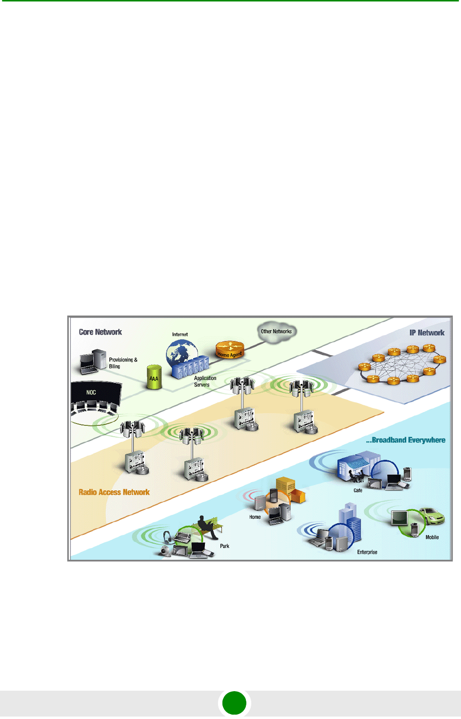
Chapter 1 - System Description 4Motion Solution
4Motion 5 System Manual
BTS (Base Transceiver Station) equipment with an optional localized access
service network gateway (ASN-GW):
»Indoor modular Macro BTS.
»All-outdoor modular Macro BTS.
Optional centralized, fully integrated ASN-GW, which may be offered as a part
of an end-to-end solution that includes third-party partners' equipment
AAA servers provided by either Alvarion or its leading WiMAX partners
AlvariSTAR Element management system supporting NMS and OSS systems
Customer premises equipment and handsets
Figure 1-1 illustrates the entire service provider environment and 4Motion
solution elements within the radio access network, core network and subscriber
environment.
Alvarion believes that compliance with standard-driven open architecture protects
the infrastructure investment, and opens the system to a variety of fully
interoperable end-user devices. As such, 4Motion is designed with open
Figure 1-1: 4Motion Solution Elements
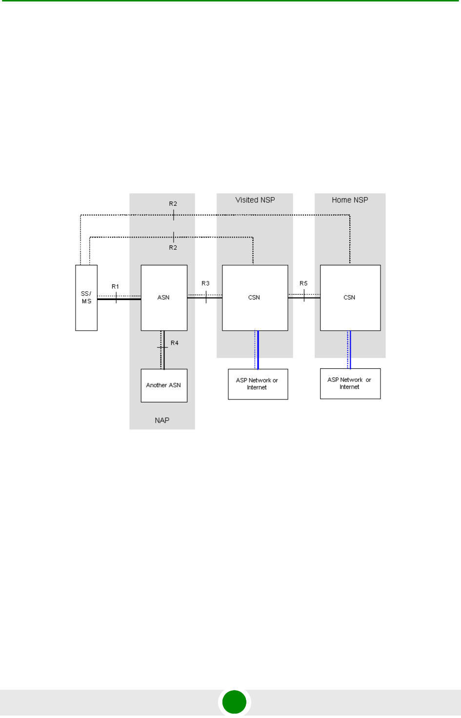
Chapter 1 - System Description 4Motion Solution
4Motion 6 System Manual
architecture and interfaces according to the WiMAX Forum networking working
group (NWG) profile C, which supports openness and enables flat as well as
hierarchical topologies. In addition, by keeping the radio resource management
functionality in the Base Transceiver Station only, Profile C delivers a faster,
optimized handover mechanism.
1.2.2 WiMAX Network Reference Model
Figure 1-2 and Figure 1-3 show the basic mobile WiMAX network architecture,
with a single ASN-GW and with multiple ASN-GWs, as defined by the WiMAX
Forum NWG.
Figure 1-2: Mobile WiMAX Network Reference Model
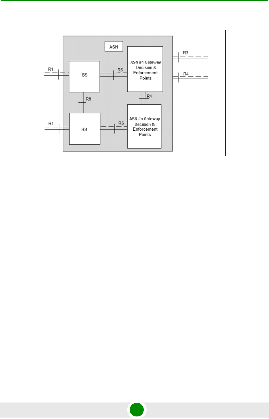
Chapter 1 - System Description 4Motion Solution
4Motion 7 System Manual
The various components and entities involved in the networking architecture are:
1.2.2.1 Access Service Network (ASN)
An ASN is defined as a complete set of network functions needed to provide radio
access to a WiMAX subscriber. The ASN provides the following mandatory
functions:
WiMAX Layer-2 (L2) connectivity with WiMAX mobile station (MS)
Transfer of AAA messages to the WiMAX subscriber's home network service
provider (H-NSP) for authentication, authorization and session accounting for
subscriber sessions
Network discovery and selection of the WiMAX subscriber's preferred NSP
Relay functionality for establishing Layer-3 (L3) connectivity with a WiMAX MS
(i.e. IP address allocation)
Radio resource management
ASN-CSN tunneling
ASN anchored mobility
Figure 1-3: ASN Reference Model containing Multiple ASN-GWs

Chapter 1 - System Description 4Motion Solution
4Motion 8 System Manual
An ASN is comprised of network elements such as one or more base transceiver
stations and one or more ASN gateways. An ASN may be shared by more than one
connectivity service network (CSN).
1.2.2.2 Connectivity Service Network (CSN)
A CSN is defined as a set of network functions that provide IP connectivity
services to WiMAX subscribers. A CSN may offer the following functions:
MS IP address and endpoint parameter allocation for user sessions
Internet access
AAA proxy or server
Policy and admission control based on user subscription profiles
ASN-CSN tunneling support
WiMAX subscriber billing and inter-operator settlement
WiMAX services such as location-based services, connectivity for peer-to-peer
services, provisioning, authorization and/or connectivity to IP multimedia
services, and facilities to support lawful intercept services such as those
compliant with Communications Assistance Law Enforcement Act (CALEA)
procedures
A CSN is comprised of network elements such as routers, proxy/servers, user
databases, and inter-working gateway devices.
1.2.2.3 Network Access Provider (NAP)
An NAP is a business entity that provides WiMAX radio access infrastructure to
one or more WiMAX network service providers (NSPs). A NAP implements this
infrastructure using one or more ASNs.
1.2.2.4 Network Service Provider (NSP)
An NSP is a business entity that provides IP connectivity and WiMAX services to
WiMAX subscribers compliant with the established service level agreement. The
NSP concept is an extension of the Internet service provider (ISP) concept,
providing network services beyond Internet access. To provide these services, an
NSP establishes contractual agreements with one or more NAPs. An NSP may also
establish roaming agreements with other NSPs and contractual agreements with

Chapter 1 - System Description 4Motion Solution
4Motion 9 System Manual
third-party application providers (e.g. ASP, ISP) for the delivery of WiMAX services
to subscribers. From a WiMAX subscriber standpoint, an NSP may be classified as
a home or visited NSP.
1.2.2.5 Base Station (BS)
The WiMAX BS is an entity that implements the WiMAX MAC and PHY in
compliance with the IEEE 802.16e standard. A BS operates on one frequency
assignment, and incorporates scheduler functions for uplink and downlink
resources.
The basic functionality of the BS includes:
IEEE 802.16e OFDMA PHY/MAC entity
R6 and R8 functionality according to NWG definitions
Extensible Authentication Protocol (EAP) relay
Control message authentication
User traffic authentication and encryption
Handover management
QoS service flow management entity
1.2.2.6 ASN Gateway (ASN-GW)
The ASN-GW is a network entity that acts as a gateway between the ASN and
CSN. The ASN functions hosted in an ASN-GW may be viewed as consisting of two
groups - the decision point (DP) and enforcement point (EP). The EP includes
bearer plane functions, and the DP includes non-bearer plane functions.
The basic DP functionality of the ASN-GW includes:
Implementation of EAP Authenticator and AAA client
Termination of RADIUS protocol against the selected CSN AAA server (home or
visited AAA server) for MS authentication and per-MS policy profile retrieval
Storage of the MS policy profile
Generation of authentication key material
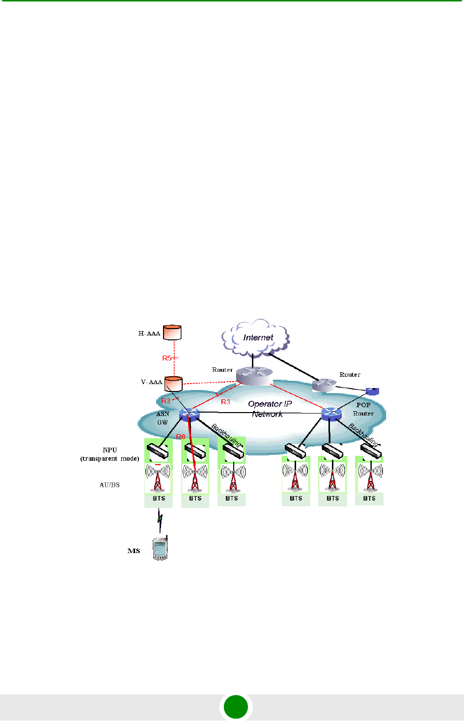
Chapter 1 - System Description 4Motion Solution
4Motion 10 System Manual
QoS service flow authorization entity
AAA accounting client
The basic EP functionality of the ASN-GW includes:
Classification of downlink data into generic routing encapsulation (GRE)
tunnels
Packet header suppression functionality
DHCP functionality
Handover functionality
The WIMAX Forum NWG has adopted two different approaches for ASN
architecture - centralized and distributed: In the centralized approach there is at
least one central ASN-GW, and the NPU operates in transparent mode, as shown
in Figure 1-4.
Figure 1-4: Centralized Network Reference Model
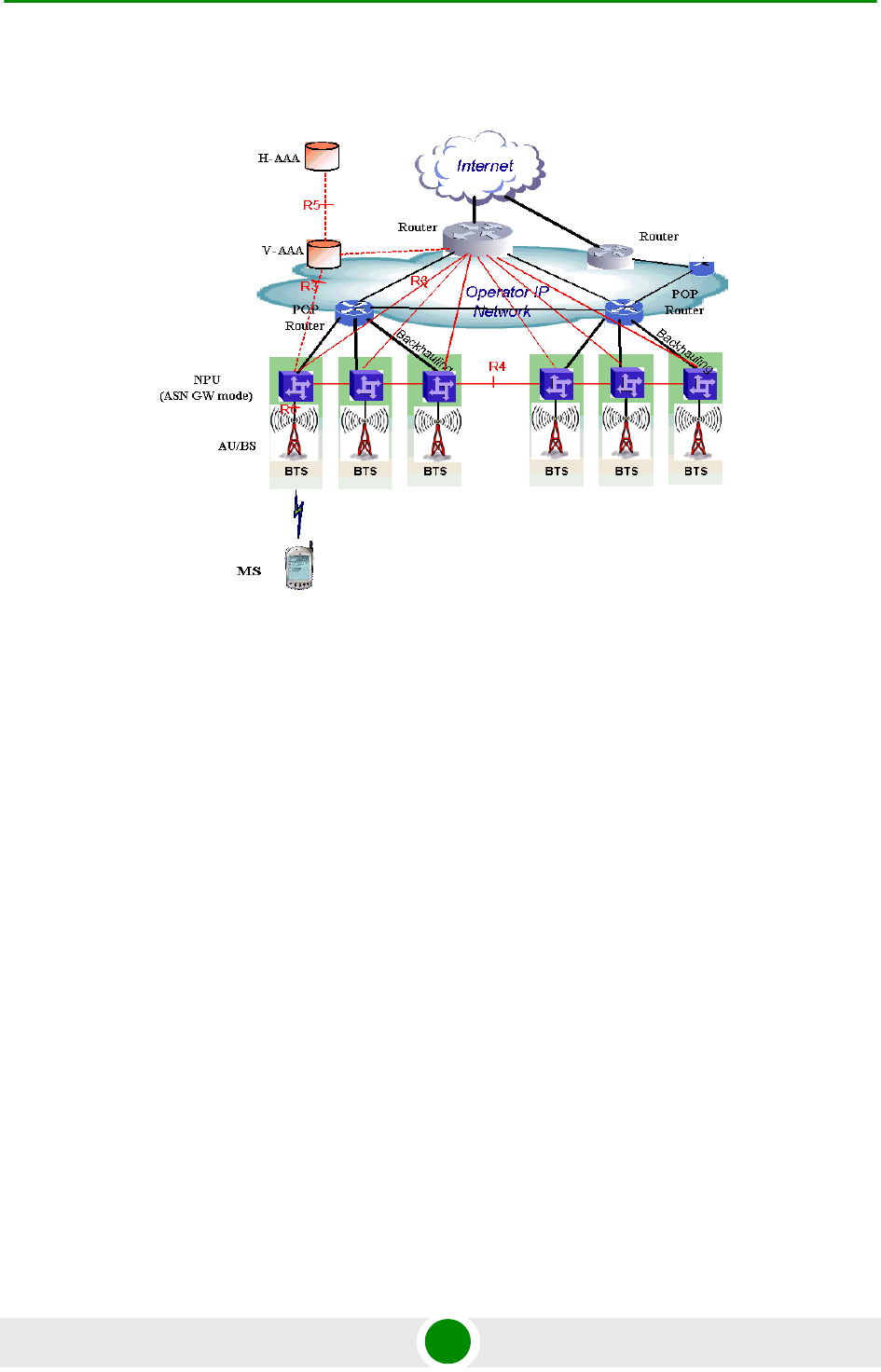
Chapter 1 - System Description 4Motion Solution
4Motion 11 System Manual
In the distributed approach, the NPU operates in ASN-GW mode, as shown in
Figure 1-5.
Alvarion believes in providing operators with the flexibility to select the mobile
WiMAX network topology that best suits their needs and existing network
architecture. Therefore, 4Motion is designed to support both distributed and
centralized topology approaches according to WiMAX Forum NWG profile C.
1.2.2.7 Reference Points
Reference point R1 consists of the protocols and procedures between the MS
and ASN as per the air-interface (PHY and MAC) specifications (IEEE 802.16e).
Reference point R2 consists of protocols and procedures between the MS and
CSN associated with authentication, services authorization and IP host
configuration management. This reference point is logical in that it does not
reflect a direct protocol interface between the MS and CSN. The authentication
part of reference point R2 runs between the MS and CSN operated by the
home NSP, however, the ASN and CSN operated by the visited NSP may
partially process the aforementioned procedures and mechanisms. Reference
point R2 might support IP host configuration management running between
the MS and CSN (operated by either the home NSP or visited NSP).
Figure 1-5: Distributed Network Reference Model

Chapter 1 - System Description 4Motion Solution
4Motion 12 System Manual
Reference point R3 consists of the set of control plane protocols between the
ASN and CSN to support AAA, policy enforcement and mobility management
capabilities. It also encompasses the bearer plane methods (e.g. tunneling) to
transfer user data between the ASN and CSN.
Reference point R4 consists of the set of control and bearer plane protocols
originating/terminating in various functional entities of an ASN that
coordinate MS mobility between ASNs and ASN-GWs. R4 is the only
interoperable reference point between similar or heterogeneous ASNs.
Reference point R5 consists of the set of control plane and bearer plane
protocols for internetworking between the CSN operated by the home NSP and
that operated by a visited NSP.
Reference point R6 consists of the set of control and bearer plane protocols
for communication between the BS and ASN-GW. The bearer plane consists of
an intra-ASN data path between the BS and ASN gateway. The control plane
includes protocols for data path establishment, modification and release
control in accordance with the MS mobility events.
Reference point R8 consists of the set of control plane message flows and
optional bearer plane data flows between the base stations to ensure a fast
and seamless handover. The bearer plane consists of protocols that allow data
transfer between base stations involved in the handover of a certain MS.
It is important to note that all reference points are logical and do not necessarily
imply a physical or even direct connection. For instance, the R4 reference point
between ASN-GWs might be implemented across the NAP internal transport IP
network, in which case R4 traffic might traverse several routers from the source to
the destination ASN-GW.

Chapter 1 - System Description The Base Transceiver Station
4Motion 13 System Manual
1.3 The Base Transceiver Station
The 4Motion solution features a multi-carrier, high-power Base Transceiver
Station (BTS). Designed for high availability and redundancy, it utilizes a central
networking and management architecture, and a range of diversity schemes.
The BTS main features include:
R1 support - 802.16e interface handling (e.g. PHY, MAC, CS, Scheduler, ARQ)
and processes such as handover, power control and network entry
R6 support - communication with ASN-GW
EAP proxy in ASN-GW mode
Handover triggering for mobility tunnel establishment - R6 (GRE tunnel)
Local QoS PEP for traffic via air interface (or SFM) and admission control
Hand-Over (HO) control function
Radio resource management agent
Key generation (TEK, KEK) and traffic encryption
The 4Motion Base Transceiver Station equipment includes:
The indoor modular Macro BTS.
The all-outdoor modular Macro BTS.
Outdoor Radio Units.
GPS Receiver
Power-Feeder (optional for the indoor Macro BTS).
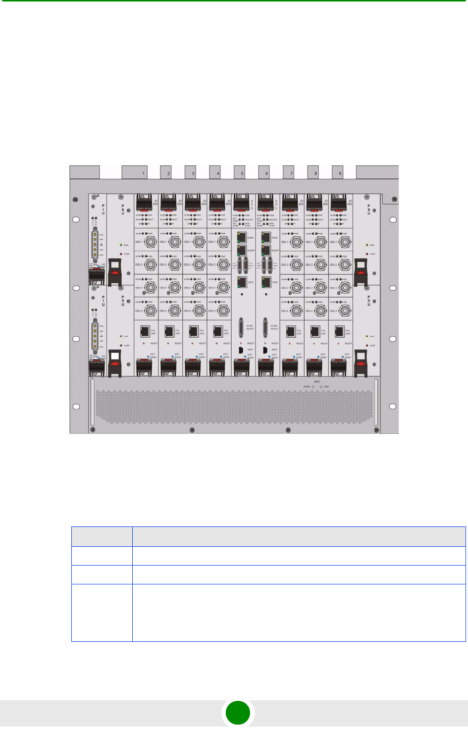
Chapter 1 - System Description The Base Transceiver Station
4Motion 14 System Manual
1.3.1 The Indoor Macro BTS
1.3.1.1 The BreezeMAX Shelf
The BreezeMAX shelf is an indoor -48 VDC powered 8U cPCI PICMG 2.x standard
shelf prepared for installation in a 19" or 21" (ETSI) rack. This chassis has a total
of nine double-Euro (6U high) slots and six single-Euro (3U high) slots. All the
modules are hot swappable, and high availability can be provided through
multiple redundancy schemes.
The shelf modules are:
Figure 1-6: BreezeMAX Shelf (with all modules installed)
Table 1-1: BreezeMAX Shelf Modules
Module Description
PIU 3U high power interface unit, 1+1 redundancy, -48VDC, protection, filters
PSU 3U high power supply unit, up to 3+1 redundancy
NPU 6U high network processing unit with optional ASN-GW functionality, hardware
ready for 1+1 redundancy (NPU redundancy is not supported in the current
release), 1000/100 Base-T main network interface, 1000/100 Base-T cascade
interface and 100/10 Base-T out-of-band management interface

Chapter 1 - System Description The Base Transceiver Station
4Motion 15 System Manual
The six single-Euro slots are intended for one or two redundant Power Interface
Units (PIUs) and up to four redundant Power Supply Units (PSUs). One of the
double Euro slots (Slot 5) is dedicated to the NPU module, with interfaces for
network backhaul, in-band and out-of-band (OOB) management connections.
Another double-Euro slot (Slot 6) is reserved for an optional redundant NPU (the
shelf is HW-ready for NPU redundancy). The remaining seven double-Euro slots
(1-4, 7-9) are dedicated for Access Unit (AU) modules, thereby enabling various
network topologies with up to 6 simultaneously operational AUs, and future
redundancy configurations. In addition, the shelf contains an Air Ventilation Unit
(AVU).
1.3.1.2 NPU
The Network Processing Unit is the controller of the Base Transceiver Station.
Serving as the central processing unit that manages the BTS components, the
NPU aggregates traffic to/from the AU modules, and transfers it to/from the IP
backbone through a dedicated Gigabit/Fast Ethernet interface. In addition, the
NPU can be operated in ASN-GW mode, in which case it also implements ASN-GW
functionality.
When operating in ASN-GW mode, the NPU implements the R3 reference point
toward the CSN, R4 reference point toward other ASN-GWs, and R6 reference
point toward AU/BSs. The R8 reference point traffic is transparently relayed
between AU/BSs (intra- or inter-BTS).
When operating in transparent mode, the NPU transparently relays R6 and R8
reference-point traffic between AU/BSs (intra- or inter-BTS).
The BreezeMAX shelf is hardware-ready for 1+1 NPU card redundancy.
The NPU main functions, when operating in transparent mode, are:
Aggregate backbone Ethernet connectivity for user and control traffic
Aggregate backbone Ethernet connectivity for management traffic (in-band or
out-of-band)
Connection to a cascaded shelf (future feature)
AU 6U high access unit, 4-channel, 802.16e MAC-modem-baseband IF card
AVU 2U high air ventilation unit, 9+1 redundancy fans with alarm control
Table 1-1: BreezeMAX Shelf Modules
Module Description

Chapter 1 - System Description The Base Transceiver Station
4Motion 16 System Manual
L2 switch forwarding capabilities
Internal and external traffic VLAN encapsulation
QoS marking
Overall operation, control and shelf management, including AU diagnostics
and control, PSU monitoring, AVU management and redundancy support
Local and remote extensive management support via CLI (Telnet, SSH) and
SNMP, including software download, fault and performance management
Alarm management, including external alarm inputs and activation of external
devices
Synchronization, including GPS receiver interface, clock and IF reference
generation and distribution to the shelf modules, and holdover handling
Security functionalities such as rate limiting and access control lists
When operating in ASN-GW mode, the following additional ASN-GW functions are
supported:
EAP authenticator
RADIUS AAA client
AAA accounting client
MS policy profile storage
QoS service flow authorization
Classification of downlink data into service flows
Packet header suppression functionality
Multiple service provider support (multihost) for improved security and
wholesale model
DHCP functionality - internal server, DHCP proxy, DHCP relay (with Option 82
support)

Chapter 1 - System Description The Base Transceiver Station
4Motion 17 System Manual
Handover functionality
GRE encapsulation/decapsulation
IP-in-IP encapsulation/decapsulation
Transparent VLAN (single tag) and QinQ (dual tag) encapsulation
Fragmentation/reassembly
R4/R6/R3 interfaces implementation
Keep-alive signaling towards the relevant BSs and other ASN-GWs for
enhanced management of service availability
When several shelves are collocated, the NPU cascade interface can be used for
shelf interconnection. In this architecture, the NPU that is directly connected to
the backhaul implements a layer-2 connection toward the NPUs in the cascaded
shelves. Bearer, control and management traffic is sent over the cascade
connection. Synchronization and GPS backup power are sent toward the NPUs in
the cascaded shelves through the GPS/SYNC ports.
GPS synchronization cascading will be implemented in a future release.
1.3.1.3 AU
The Access Unit module performs the WiMAX/IEEE 802.16e BS function
according to the NWG Profile C definitions via digital signal processors (DSPs) and
field-programmable gate array (FPGA) technology. The AU module is designed to
support high-traffic throughput and enable diversity, MIMO and AAS, thereby
extending capacity and range.
The AU implements the following functionality:
802.16e multi-channel OFDMA PHY
Up to four-channel support (Tx/Rx)
Diversity and future AAS
Flexible channel bandwidth - up to 20 MHz
Flexible FFT size - up to 2048 points

Chapter 1 - System Description The Base Transceiver Station
4Motion 18 System Manual
Wide variety of reuse patterns
Advanced channel coding (CTC)
HARQ
Rate adaptation
High-performance CDMA detector
IF interface to RF ODU
MAC-PHY interface
Link management (network entry, basic capabilities negotiation,
authentication and registration, connection management)
Fragmentation/ reassembly
QoS PEP for air interface traffic
QoS DSCP marking
Scheduling - connections quota computation for all data delivery types
Frame/burst building
Power save
Handover management
Power control
R1/R6/R8 functionality
Data path mapping between R6 (GRE) and 802.16e interfaces
Traffic authentication and encryption
Authentication relay
Security key receiver

Chapter 1 - System Description The Base Transceiver Station
4Motion 19 System Manual
Context client/server
ID to IP address resolution for ASN entities
IP and Ethernet convergence sublayers
Keep-alive signaling towards the relevant ASN-GWs for enhanced management
of service availability
The AU design is based on Alvarion's programmable, off-the-shelf, cutting-edge
components, in order to provide a future-proof solution with excellent cost and
performance.
The AU card interfaces with the NPU card for R6/R8 functionality, as well as
control, synchronization and management between the NPU and AU.
The AU implements four receive and transmit channels, each of them is HW-ready
for up to 20 MHz bandwidth.
1.3.1.4 PIU
The single-Euro Power Interface Unit module serves as the interface between the
DC power source and both the PSU modules and external ODU radio transceivers.
The PIU filters and stabilizes the input power, and protects the system from power
problems such as over-voltage, surge pulses, reverse polarity connection, and
short circuits. It filters high-frequency interference (radiated emissions) and
low-frequency interference (conducted emissions) at the external power source.
Each shelf contains two slots for optional 1+1 PIU redundancy. One PIU is
sufficient to support a fully populated shelf, and two modules provide redundant
power feeding (i.e. from two input sources), while avoiding current flow between
the two input sources.
1.3.1.5 PSU
The single-Euro Power Supply Unit module is a -48 VDC power supply unit that
generates low-voltage DC output to comply with PICMG 2.x standard
requirements. Each shelf can contain up to four PSU modules supporting N+1
redundancy configuration scheme.
Table 1-2 displays the number of PSU modules (excluding redundant units)
required for various Base Station configurations without NPU redundancy (one
NPU):

Chapter 1 - System Description The Base Transceiver Station
4Motion 20 System Manual
1.3.1.6 AVU
The 2U-high AVU includes a 1U-high integral chamber for inlet airflow and a
1U-high fan tray with an internal alarm module. To support high availability, the
fan tray includes 10 brushless fans (9 fans are sufficient for cooling a fully-loaded
shelf). Fan failure is indicated by both the front panel LEDs and a trap sent to the
management system. To further support high availability, the chassis may
operate without the hot-swappable fan tray for up to 10 minutes until the AVU is
replaced.
1.3.2 The Macro Outdoor BTS
The Macro Outdoor BTS is a modular scalable and reliable all-outdoor platform
enabling extended and flexible installation capabilities while sustaining all the
features and capabilities of the 4Motion solution.
The All-Outdoor Macro BTS portfolio includes the following system elements:
NAU (Network Access Unit): A full-size enclosure containing NPU and AU
cards.
DAU (Dual Access Unit): A full-size enclosure containing two AU cards.
SAU (Single Access Unit): A half-size enclosure containing one AU card.
The full-size enclosure is similar to the enclosure of the 4x2 ODUs (see
Section 1.3.3), supporting flexible mounting options for system components,
including back-to-back and side-by-side mounting. The units are available with
either full (4-channels) AUs or with 2-channels AUs.
The modular architecture and different unit types enable building a variety of
configurations using up to six AUs with either 2 or 4 channels, addressing a
pay-as-you-grow deployment. The functionality is the same as described for the
NPU (see Section 1.3.1.2) and AU (see Section 1.3.1.3) cards of the Indoor Macro
BTS, with a few minor exceptions.
Table 1-2: PSU Requirements, Configurations with one NPU (excluding PSU
redundancy)
Number of AUs Minimum Required Number of PSUs
1 - 4 2
5 - 6 3

Chapter 1 - System Description The Base Transceiver Station
4Motion 21 System Manual
1.3.3 ODU
The outdoor unit (ODU) is a high-power, multi-carrier radio unit that connects to
one or more external antennas. It is designed to provide high system gain and
interference robustness utilizing high transmit power and low noise figure. It is
HW-ready for supporting a bandwidth of up to 20 MHz, enabling future options
such as increased capacity through the use of a multiplexer or wider frequency
channels.
The following ODU port configurations will be available:
1x1(1Rx by 1 Tx): One receive port, one transmit port (one Tx/Rx interface)
2x2 (2Rx by 2Tx): Two receive ports, two transmit ports (two Tx/Rx interfaces)
4x2 (4Rx by 2Tx): Four receive ports, two transmit ports (two Tx/Rx interfaces,
two Rx only interfaces)
The wide range of ODU types will enable efficient utilization of various second and
fourth order transmit and receive diversity schemes.
The following table provides details on the currently available ODUs following the
WiMAX Forum’s definitions:
Table 1-3: ODU Types
Band (GHz) ODU Frequency Range
(MHz) ODU Port
Configuration ODU Bandwidth
(MHz) ODU Max Tx
Power (dBm)
2.0 2020-2220 1Rx by 1Tx Up to 10 36
2.3 2300-2360 1Rx by 1Tx Up to 10 36
2340-2400 1Rx by 1Tx Up to 10 36
2305 - 2317, 2348 - 2360
(includes WCS filter)
1Rx by 1Tx Up to 10 36
2300-2400 2Rx by 2Tx Up to 30 38

Chapter 1 - System Description The Base Transceiver Station
4Motion 22 System Manual
1.3.4 Power Feeder
The PIU of the indoor Macro BTS can support a maximum current of 58 A (@-40.5
VDC). In certain installations with a relatively high number of ODUs this current
may not be sufficient to power the shelf and all the ODUs. In such installations
the ODU Power Feeder is used as an additional power source providing power (-48
VDC) to ODUs. It transfers transparently all signals between the AU and the ODU,
while injecting DC power received from an external source. Each ODU Power
Feeder unit can serve up to four ODUs. Up to three ODU Power Feeder units can
be installed in a 1U high Power Feeder panel.
1.3.5 Antenna
In the 4Motion architecture, the antenna is approached as an independent
element. This provides the operator with the flexibility to select the antennas
source according to its supplier policy. To ensure the availability of antennas that
2.5 2496-2602 (band A) 1Rx by 1Tx Up to 10 36
2590-2690 (band B) 1Rx by 1Tx Up to 10 36
2485-2690 2Rx by 2TX Up to 30 38 (37 in the
2485-2495
GHz band)
2496-2602 (band A) 4Rx by 2Tx Up to 20 38
2590-2690 (band B) 4Rx by 2Tx Up to 20 38
2485-2690 4Rx by 2Tx Up to 20 38 (37 in the
2485-2695
GHz band)
2560-2570 4Rx by 2Tx Up to 10 37
3.3 3300-3355 1Rx by 1 Tx Up to 14 32
3.5 3400-3455 1Rx by 1Tx Up to 14 34
3445-3500 1Rx by 1Tx Up to 14 34
3500-3555 1Rx by 1Tx Up to 14 34
3545-3600 1Rx by 1Tx Up to 14 34
3400-3600 2Rx by 2Tx Up to 30 37
3400-3600 4Rx by 2Tx Up to 20 37
3.6 3600-3800 4Rx by 2Tx Up to 20 36
Table 1-3: ODU Types
Band (GHz) ODU Frequency Range
(MHz) ODU Port
Configuration ODU Bandwidth
(MHz) ODU Max Tx
Power (dBm)

Chapter 1 - System Description The Base Transceiver Station
4Motion 23 System Manual
complement the 4Motion solution, Alvarion works closely with several antenna
suppliers to ensure availability of antennas that comply with its requirements.
In cases where the operator prefers other antenna vendors, Alvarion can provide a
recommended antenna specification based on the required antennas types.
For more information on recommended antenna configurations and required
antennas refer to “Antenna Configurations” on page 681.
1.3.6 GPS
GPS is used to synchronize the air link frames of Intra-site and Inter-site located
Base Transceiver Stations to ensure that in all Base Stations the air frame will
start at the same time, and that all Base Stations will switch from transmit
(downlink) to receive (uplink) at the same time. This synchronization is necessary
to prevent Intra-site and Inter-site interference and Base stations saturation
(assuming that all Base Stations are operating with the same frame size and with
the same DL/UL ratio).
In order for the system to be synchronized, the GPS have to first acquire at least 4
satellites. After that the GPS reception can be reduced to 1 satellite.If no satellite
is received the BTS will go to holdover state where internal clock is provided to
synchronize the BTS.
1.3.6.1 Outdoor GPS Receiver
The all-outdoor GPS Receiver is a pole mountable GPS receiver and antenna in a
single environmentally protected enclosure. The GPS Receiver is powered by a 12
VDC power source, supplied to it by the NPU. The RS-422 interface allows
installation at distances up to 100m.

Chapter 1 - System Description Element Management Systems
4Motion 24 System Manual
1.4 Element Management Systems
The end-to-end IP-based architecture of the system enables full management of
all components, using standard management tools. An SNMP agent in the NPU
implements proprietary MIBs for remote setting of operational modes and
parameters of the Base Transceiver Station equipment. Security features
incorporated in the equipment restrict the access for management purposes.
Alvarion offers the following management tool:
1.4.1 AlvariSTAR
AlvariSTAR is a comprehensive carrier-class Element Management System (EMS)
for Alvarion’s Broadband Wireless Access systems. AlvariSTAR is designed for
today's most advanced Network Operation Centers (NOCs), providing the network
Operation, Administration and Maintenance (OA&M) staff and managers with all
the network surveillance, monitoring and configuration and service provisioning
capabilities required to effectively manage the network while keeping the
resources and expenses at a minimum.
AlvariSTAR offers the network's OA&M staff with a unified, scalable and
distributable management system. Utilizing distributed client-server architecture,
the user is provided with a robust, scalable and fully redundant management
system in which all single points of failure can be avoided.
AlvariSTAR provides the following management functionality:
Device Discovery
Device Inventory
Topology
Fault Management
Configuration Management
Service Management
Data Collection
Performance Monitoring

Chapter 1 - System Description Element Management Systems
4Motion 25 System Manual
Device embedded software upgrade
BTS duplication and template-based configuration modification of multiple
BTS simultaneously.
Security Management
Event Forwarding to other Network Management Systems.

Chapter 1 - System Description Specifications
4Motion 26 System Manual
1.5 Specifications
1.5.1 Modem & Radio
1.5.2 Sensitivity
Table 1-4: General Modem & Radio Specifications
Item Description
Operation Mode TDD
Channel Bandwidth 5 MHz
7 MHz
10 MHz
Central Frequency Resolution 0.125 MHz (actual configurable frequencies depend on the
local radio regulations and allocated spectrum)
Modulation OFDM modulation, 1024/512 FFT points;
QPSK, QAM16, QAM64
Access Method OFDMA
FEC Convolutional Turbo Coding: 1/2, 2/3, 3/4, 5/6
Table 1-5: Sensitivity, AWGN @ PER=1%
Modulation
& Coding Sensitivity (dBm),
5 MHz Bandwidth Sensitivity (dBm),
7 MHz Bandwidth Sensitivity (dBm),
10 MHz Bandwidth
QPSK 1/2 -97.3 -95.8 -94.2
QPSK 3/4 -94.9 -93.4 -91.8
16QAM 1/2 -92.2 -90.7 -89.1
16QAM 3/4 -88.3 -86.8 -85.2
64QAM1/2 -86.8 -85.3 -83.7
64QAM2/3 -83.0 -81.5 -79.9
64QAM3/4 -82.2 -80.7 -79.1
64QAM5/6 -81.0 -79.5 -77.9

Chapter 1 - System Description Specifications
4Motion 27 System Manual
1.5.3 ODUs
1.5.3.1 2.0 GHz Band
Table 1-6: 2.0 GHz Band 1x1 ODU Specifications
Item Description
Frequency Band ODU-2020-2220-000N-36-1x1-N-0: 2020-2220 MHz
Ports Configuration 1x1 (1Rx, 1Tx)
Bandwidth Support Up to 10 MHz
Maximum Tx Power ) 36 dBm
Tx Power Control Range 6 dB, in 1 dB steps
Tx Power Accuracy +/- 1 dB
Maximum Input Power @ antenna port -60 dBm before saturation, -8 dBm before damage
Noise Figure 4.6 dB typical, 6.0 dB maximum
Dimension 329 x 157 x 169 mm
Weight 6.1 Kg
Connectors ANT: N-Type jack, 50 Ohm, lightning protected
IF: TNC jack, 50 Ohm, lightning protected
Power Source -40.5 to -60 VDC over the IF cable
Power Consunption Transmit - 89W maximum, 75W typical
Receive - 15W maximum, 9W typical

Chapter 1 - System Description Specifications
4Motion 28 System Manual
1.5.3.2 2.3 GHz Band
1.5.3.2.1 2.3 GHz Band 1x1 ODUs
Table 1-7: 2.3 GHz Band 1x1 ODUs Specifications
Item Description
Frequency Band ODU-HP-2.3: 2300-2360 MHz
ODU-HP-2.3-WCS: 2305 - 2317, 2348 - 2360 MHz
(incliudes WCS filter)
ODU-HP-2.3b: 2340-2400 MHz
Ports Configuration 1x1 (1Rx, 1Tx)
Bandwidth Support Up to 10 MHz, 5 & 10 MHz SAW filters
Maximum Tx Power ) 36 dBm
Tx Power Control Range 6 dB, in 1 dB steps
Tx Power Accuracy +/- 1 dB
Maximum Input Power @ antenna port -60 dBm before saturation, -8 dBm before damage
Noise Figure 4.6 dB typical, 6.0 dB maximum
Dimension ODU-HP-2.3-WCS: 329 x 157 x 209 mm
Other ODUs: 329 x 157 x 169 mm
Weight ODU-HP-2.3-WCS: 8.6 Kg
Other ODUs: 6.1 Kg
Connectors ANT: N-Type jack, 50 Ohm, lightning protected
IF: TNC jack, 50 Ohm, lightning protected
Power Source -40.5 to -60 VDC over the IF cable
Power Consunption Transmit - 89W maximum, 75W typical
Receive - 15W maximum, 9W typical

Chapter 1 - System Description Specifications
4Motion 29 System Manual
1.5.3.2.2 2.3 GHz Band 2x2 ODU
* With the optional external WCS filter, the frequency range is 2305-2315,
2350-2360 MHz, and Tx power is reduced by 1 dB.
Table 1-8: 2.3 GHz Band 2x2 ODU Specifications
Item Description
Frequency Band ODU-2300-2400-000N-38-2X2-N-0: 2300-2400 MHz*
Ports Configuration 2x2 (2Rx, 2Tx)
Bandwidth Support Up to 30 MHz
Beam Forming Support Yes
Maximum Tx Power ) 38 dBm*
Tx Power Control Range 10 dB, in 1 dB steps
Tx Power Accuracy +/- 1 dB
Maximum Input Power @
antenna port
-60 dBm before saturation, -8 dBm before damage
Noise Figure 4.5 dB typical, 5.5 dB maximum
Dimension 420 x 340 x 270 mm
Weight 15 Kg
Connectors ANT: 2 x N-Type jack, 50 Ohm, lightning protected
IF: 2 x TNC jack, 50 Ohm, lightning protected
Power Source -40.5 to -60 VDC over the IF cable
Power Consunption Transmit - 200W maximum
Receive - 40W maximum

Chapter 1 - System Description Specifications
4Motion 30 System Manual
1.5.3.3 2.5 GHz Band
1.5.3.3.1 2.5 GHz Band 1x1 ODUs
Table 1-9: 2.5 GHz Band 1x1 ODUs Specifications
Item Description
Frequency Band ODU-HP-2.5A: 2496-2602 MHz (Band A)
ODU-HP-2.5B: 2590-2690 MHz (Band B)
Ports Configuration 1x1 (1Rx, 1Tx)
Bandwidth Support Up to 10 MHz
Maximum Tx Power ) 36 dBm
Tx Power Control Range 6 dB, in 1 dB steps
Tx Power Accuracy +/- 1 dB
Maximum Input Power @
antenna port
-60 dBm before saturation, -8 dBm before damage
Noise Figure 4.6 dB typical, 6.0 dB maximum
Dimension 329 x 157 x 209 mm
Weight 6.1 Kg
Connectors ANT: N-Type jack, 50 Ohm, lightning protected
IF: TNC jack, 50 Ohm, lightning protected
Power Source -40.5 to -60 VDC over the IF cable
Power Consunption Transmit - 89W maximum, 75W typical
Receive - 15W maximum, 9W typical

Chapter 1 - System Description Specifications
4Motion 31 System Manual
1.5.3.3.2 2.5 GHz Band 2x2 ODUs
Table 1-10: 2.5 GHz Band 2x2 ODUs Specifications
Item Description
Frequency Band ODU-2485-2690-000N-38-2X2-N-0: 2485-2690 MHz
Ports Configuration 2x2 (2Rx, 2Tx)
Bandwidth Support Up to 30 MHz
Beam Forming Support Yes
Maximum Tx Power ) 38 dBm (37 dBm in the 2485-2495 MHz range)
Tx Power Control Range 10 dB, in 1 dB steps
Tx Power Accuracy +/- 1 dB
Maximum Input Power @
antenna port
-60 dBm before saturation, -8 dBm before damage
Noise Figure 4.5 dB typical, 5.5 dB maximum
Dimension 420 x 340 x 270 mm
Weight 15 Kg
Connectors ANT: 2 x N-Type jack, 50 Ohm, lightning protected
IF: 2 x TNC jack, 50 Ohm, lightning protected
Power Source -40.5 to -60 VDC over the IF cable
Power Consunption Transmit - 200W maximum
Receive - 40W maximum

Chapter 1 - System Description Specifications
4Motion 32 System Manual
1.5.3.3.3 2.5 GHz Band 4x2 ODUs
Table 1-11: 2.5 GHz Band 4x2 ODUs Specifications
Item Description
Frequency Band ODU-2496-2602-000N-38-4x2-N-0: 2496-2602 MHz (Band A)
ODU-2590-2690-000N-38-4x2-N-0: 2590-2690 MHz (Band B)
ODU-2485-2690-000N-38-4X2-N-0: 2485-2690 MHz
ODU-2560-2570-000N-37-4X2-N-0: 2560-2570 MHz
Ports Configuration 4x2 (4Rx, 2Tx)
Bandwidth Support Up to 20 MHz
Maximum Tx Power ) 38 dBm
For ODU-2485-2690-000N-38-4X2-N-0: 37 dBm in the 2485-2495
MHz range.
For ODU-2560-2570-000N-37-4X2-N-0: 37 dBm.
Tx Power Control Range 10 dB, in 1 dB steps
Tx Power Accuracy +/- 1 dB
Maximum Input Power @
antenna port
-60 dBm before saturation, -8 dBm before damage
Noise Figure 4.5 dB typical, 5.5 dB maximum
Dimension 420 x 340 x 270 mm
Weight 15 Kg
Connectors ANT: 4 x N-Type jack, 50 Ohm, lightning protected
IF: 4 x TNC jack, 50 Ohm, lightning protected
Power Source -40.5 to -60 VDC over the IF cable
Power Consunption Transmit - 284W maximuml
Receive - 70W maximum

Chapter 1 - System Description Specifications
4Motion 33 System Manual
1.5.3.4 3.3 GHz Band
Table 1-12: 3.3 GHz Band 1x1 ODU Specifications
Item Description
Frequency Band ODU-3300-3355-000N-32-1x1-N-0: 3300-3355 MHz
Ports Configuration 1x1 (1Rx, 1Tx)
Bandwidth Support Up to 14 MHz
Maximum Tx Power 32 dBm
Tx Power Control Range 10 dB, in 1 dB steps
Tx Power Accuracy +/- 1 dB
Maximum Input Power @
antenna port
-60 dBm before saturation, -8 dBm before damage
Noise Figure 4.5 dB typical, 5.5 dB maximum
Dimension 329 x 157 x 169 mm
Weight 6.1 Kg
Connectors ANT: N-Type jack, 50 Ohm, lightning protected
IF: TNC jack, 50 Ohm, lightning protected
Power Source -40.5 to -60 VDC over the IF cable
Power Consunption Transmit - 90W maximum, 62W typical
Receive - 20W maximum, 14W typical

Chapter 1 - System Description Specifications
4Motion 34 System Manual
1.5.3.5 3.5 GHz Band
1.5.3.5.1 3.5 GHz Band 1x1 ODUs
Table 1-13: 3.5 GHz Band 1x1 ODUs Specifications
Item Description
Frequency Band ODU-HP-TDD-3.4a: 3400-3455 MHz
ODU-HP-TDD-3.4b: 3445-3500 MHz
ODU-HP-TDD-3.5a: 3500-3555 MHz
ODU-HP-TDD-3.5b: 3545-3600 MHz
Ports Configuration 1x1 (1Rx, 1Tx)
Bandwidth Support Up to 14 MHz
Maximum Tx Power 34 dBm
Tx Power Control Range 10 dB, in 1 dB steps
Tx Power Accuracy +/- 1 dB
Maximum Input Power @
antenna port
-60 dBm before saturation, -8 dBm before damage
Noise Figure 4.5 dB typical, 5.5 dB maximum
Dimension 329 x 157 x 169 mm
Weight 6.1 Kg
Connectors ANT: N-Type jack, 50 Ohm, lightning protected
IF: TNC jack, 50 Ohm, lightning protected
Power Source -40.5 to -60 VDC over the IF cable
Power Consunption Transmit - 90W maximum, 62W typical
Receive - 20W maximum, 14W typical

Chapter 1 - System Description Specifications
4Motion 35 System Manual
1.5.3.5.2 3.5 GHz Band 2x2 ODUs
Table 1-14: 3.5 GHz Band 2x2 ODUs Specifications
Item Description
Frequency Band ODU-3400-3600-000N-37-2x2-N-0: 3400-3600 MHz
Ports Configuration 2x2 (2Rx, 2Tx)
Bandwidth Support Up to 30 MHz
Beam Forming Support Yes
Maximum Tx Power ) 37 dBm
Tx Power Control Range 10 dB, in 1 dB steps
Tx Power Accuracy +/- 1 dB
Maximum Input Power @
antenna port
-60 dBm before saturation, -8 dBm before damage
Noise Figure 4.5 dB typical, 5.5 dB maximum
Dimension 420 x 340 x 270 mm
Weight 15 Kg
Connectors ANT: 2 x N-Type jack, 50 Ohm, lightning protected
IF: 2 x TNC jack, 50 Ohm, lightning protected
Power Source -40.5 to -60 VDC over the IF cable
Power Consunption Transmit - 200W maximum
Receive - 240W maximum

Chapter 1 - System Description Specifications
4Motion 36 System Manual
1.5.3.5.3 3.5 GHz Band 4x2 ODUs
Table 1-15: 3.5 GHz Band 4x2 ODUs Specifications
Item Description
Frequency Band ODU-3400-3600-000N-37-4x2-N-0: 3400-3600 MHz
Ports Configuration 4x2 (4Rx, 2Tx)
Bandwidth Support Up to 20 MHz
Maximum Tx Power ) 37 dBm
Tx Power Control Range 10 dB, in 1 dB steps
Tx Power Accuracy +/- 1 dB
Maximum Input Power @
antenna port
-60 dBm before saturation, -8 dBm before damage
Noise Figure 4.5 dB typical, 5.5 dB maximum
Dimension 420 x 340 x 270 mm
Weight 15 Kg
Connectors ANT: 4 x N-Type jack, 50 Ohm, lightning protected
IF: 4 x TNC jack, 50 Ohm, lightning protected
Power Source -40.5 to -60 VDC over the IF cable
Power Consunption Transmit - 216W maximuml
Receive - 24W maximum

Chapter 1 - System Description Specifications
4Motion 37 System Manual
1.5.3.6 3.6 GHz Band
Table 1-16: 3.6 GHz Band 4x2 ODU Specifications
Item Description
Frequency Band ODU-3600-3800-000N-36-4x2-N-0: 3600-3800 MHz
Ports Configuration 4x2 (4Rx, 2Tx)
Bandwidth Support Up to 20 MHz
Maximum Tx Power ) 36 dBm
Tx Power Control Range 10 dB, in 1 dB steps
Tx Power Accuracy +/- 1 dB
Maximum Input Power @
antenna port
-60 dBm before saturation, -8 dBm before damage
Noise Figure 4.5 dB typical, 5.5 dB maximum
Dimension 420 x 340 x 270 mm
Weight 15 Kg
Connectors ANT: 4 x N-Type jack, 50 Ohm, lightning protected
IF: 4 x TNC jack, 50 Ohm, lightning protected
Power Source -40.5 to -60 VDC over the IF cable
Power Consunption Transmit - 216W maximuml
Receive - 24W maximum

Chapter 1 - System Description Specifications
4Motion 38 System Manual
1.5.4 AU - ODU Communication
1.5.5 Data Communication (Ethernet Interfaces)
Table 1-17: AU - ODU Communication
Item Description
IF Frequency Tx: 240 MHz
Rx: 140 MHz
Ref Synchronization Frequency 64 MHz
Bi-Directional Control Frequency 14 MHz
IF cable Impedance 50 Ohm
Maximum IF cable Attenuation 10 dB @ 240 MHz
7.5 dB @ 140 MHz
8 dB @ 64 MHz
Minimum IF cable Shielding Effectiveness 90 dB in the 10-300 MHz band
Maximum IF cable Return Loss 20 dB in the 10-300 MHz band
Maximum IF cable DC Resistance 1x1 ODUs, 2.x GHz 4x2 ODUs: 1.5 Ohm
3.x GHz 4x2 ODUs: 1 Ohm
Table 1-18: Data Communication (Ethernet Interfaces)
Item Description
Standard Compliance IEEE 802.3 CSMA/CD
Speed NPU Data Port 10/100/1000 Mbps, Full Duplex with Auto
Negotiation
NPU Management Port 10/100 Mbps, Half/Full Duplex with Auto Negotiation
NPU Cascade Port
(not applicable for NAU)
100/1000 Mbps, Full Duplex with Auto Negotiation
AU Calibration Port(not
applicable for Macto
Oudoor BTS
components, not used in
current release)
10/100 Mbps, Half/Full Duplex with Auto Negotiation

Chapter 1 - System Description Specifications
4Motion 39 System Manual
1.5.6 Configuration and Management
Table 1-19: Configuration and Management
Item Description
Out Of Band (OOB) Management Telnet via Management port
SSH via Management port
SNMP via Management port
Telnet via Cascade port (not applicable for
NAU)
SSH via Cascade port (not applicable for NAU)
SNMP via Cascade port (not applicable for
NAU)
Monitor port (serial interface)
In Band (IB) Management via Data Port SNMP
Telnet
SSH
SNMP Agents SNMP ver 2 client
MIB II (RFC 1213), Private MIBs
Software Upgrade Using TFTP
Configuration Upload/Download Using TFTP

Chapter 1 - System Description Specifications
4Motion 40 System Manual
1.5.7 Standards Compliance, General
1.5.8 Environmental
Table 1-20: Standards Compliance, General
Type Standard
EMC ETSI EN 301 489-1/4
FCC Part 15
Safety EN60950-1
UL 60950-1
Environmental ETS 300 019:
Part 2-1 T 1.2 & part 2-2 T 2.3 for indoor & outdoor
Part 2-3 T 3.2 for indoor
Part 2-4 T 4.1E for outdoor
Radio ETSI EN 302 326
ETSI EN 302 544
FCC part 15, part 27, part 25
Table 1-21: Environmental Specifications
Type Unit Details
Operating
Temperature
Outdoor units AU-ODU-HP-2.3-WCS: -52°C to 55°C
All other ODUs and Macro Outdoor BTS units: -40°C
to 55°C
Outdoor GPS Receiver: -40°C to 85°C
Indoor equipment 0°C to 40°C
Operating
Humidity
Outdoor units 8%-100%, weather protected
Indoor equipment 5%-95% non condensing

Chapter 1 - System Description Specifications
4Motion 41 System Manual
1.5.9 Mechanical and Electrical
1U = 44.45 mm (1.75”).
1HP = 5.08 mm (0.2”)
1.5.9.1 BreezeMAX Shelf
1.5.9.2 AVU
1.5.9.3 PIU
Table 1-22: BreezeMAX Shelf, Mechanical & Electrical Specifications
Item Description
Dimensions 8U ETSI type shelf, 8U x 43.2 x 24 cm
Weight 6.9 Kg (excluding AVU)
Table 1-23: AVU, Mechanical & Electrical Specifications
Item Description
Dimensions 2U x 84HP x 16 cm
Weight 1.5 Kg
Power Condumption 40W maximum, 23W typical
Table 1-24: PIU, Mechanical & Electrical Specifications
Item Description
Dimensions 3U x 5HP x 16 cm
Weight 0.45 Kg
Power Source -40.5 to -60 VDC
Power Dissipation 35W maximum (active PIU)
Maximum Supplied Current 58A
-48V Connector 5 pin/40A D-Type plug

Chapter 1 - System Description Specifications
4Motion 42 System Manual
1.5.9.4 PSU
1.5.9.5 NPU
1.5.9.6 AU
Table 1-25: PSU, Mechanical & Electrical Specifications
Item Description
Dimensions 3U x 5HP x 16 cm
Weight 0.7 Kg
Power Output 300W maximum output power
Efficiency: 80% minimum
Table 1-26: NPU, Mechanical & Electrical Specifications
Item Description
Dimensions 6U x 7HP x 16 cm
Weight 0.7 Kg
Power Consumption 68W maximum, 61W typical
Connectors DATA 100/1000Base-T (RJ-45) with 2 embedded LEDs
MGMT 10/100Base-T (RJ-45) with 2 embedded LEDs
GPS/SYNC IN 15-pin micro D-Type jack
GPS/SYNC OUT 15-pin micro D-Type jack
CSCD 100/1000Base-T (RJ-45) with 2 embedded LEDs
ALRM IN/OUT 25-pin micro D-Type jack
MON 3-pin low profile jack
Table 1-27: AU, Mechanical & Electrical Specifications
Item Description
Dimensions 6U x 7HP x 16 cm
Weight 0.6 Kg
Power Consumption 74W maximum, 66W typical
Connectors ODU1 - ODU4 4 x TNC jack, lightning protected
CAL UNIT 10/100Base-T (RJ-45) with 2 embedded LEDs

Chapter 1 - System Description Specifications
4Motion 43 System Manual
1.5.9.7 NAU
1.5.9.8 SAU
Table 1-28: NAU, Mechanical & Electrical Specifications
Item Description
Dimensions 420 x 340 x 280 mm
Weight 15 Kg
Power Source -40.5 to -60 VDC
Power Consumption 140W maximum
NPU Connectors DATA RJ-45, lightning protected
MNG RJ-45, lightning protected
GPS RJ-45, lightning protected
ETH (x5) 5 x RJ-45, lightning protected
SYNC (x3) 3 x RJ-45, lightning protected
AU Connectors POWER SAMTEC Mini Fit 6 pins
IF1-IF4 4 x TNC jack, lightning protected
SYNC -
ETH RJ-45, lightning protected (not used)
MON RJ-45, lightning protected
Table 1-29: SAU, Mechanical & Electrical Specifications
Item Description
Dimensions 420 x 340 x 140 mm
Weight 7.5 Kg
Power Source -40.5 to -60 VDC
Power Consumption 75W maximum
Connectors POWER SAMTEC Mini Fit 6 pins
IF1-IF4 4 x TNC jack, lightning protected
SYNC RJ-45, lightning protected
ETH RJ-45, lightning protected
MON Not used

Chapter 1 - System Description Specifications
4Motion 44 System Manual
1.5.9.9 DAU
* Master AU is with a SYNC connector (in the Slave AU there is no SYNC
connector)
Table 1-30: DAU, Mechanical & Electrical Specifications
Item Description
Dimensions 420 x 340 x 280 mm
Weight 15 Kg
Power Source -40.5 to -60 VDC
Power Consumption 150W maximum
Master* AU
Connectors
POWER SAMTEC Mini Fit 6 pins
IF1-IF4 4 x TNC jack, lightning protected
SYNC RJ-45, lightning protected
ETH RJ-45, lightning protected
MON Not used
Slave* AU
Connectors
POWER SAMTEC Mini Fit 6 pins
IF1-IF4 4 x TNC jack, lightning protected
SYNC Not used
ETH RJ-45, lightning protected
MON Not used

Chapter 1 - System Description Specifications
4Motion 45 System Manual
1.5.9.10 GPS Receiver
1.5.9.11 ODU Power Feeder
Table 1-31: GPS Receiver, Mechanical & Electrical Specifications
Item Description
Dimensions Tubular enclosure, 15.5 D x 12.7 H cm
Weight 0.363 Kg
Power Source 12 VDC from the NPU
Power Consumption 6W maximum
Connector 12-pin round plug
Table 1-32: ODU Power Feeder, Mechanical & Electrical Specifications
Item Description
Dimensions 15.7 x 14.6 x 3.17 cm
Weight 0.6 Kg
Power Source -40.5 to -60 VDC
Power Dissipation 2W per channel
Connectors ODU 1 - ODU 4 4 x TNC jack, lightning protected
IDU 1 - IDU 4 4 x TNC jack, lightning protected
Power 3 pin/20A D-Type plug

Chapter 1 - System Description Specifications
4Motion 46 System Manual
1.5.10 Antennas
1.5.10.1 2.x GHz Antennas
Table 1-33: BS-RET-DP-ANT 2.3-2.7 Specifications
Item Description
Frequency Band (MHz) 2300-2700
Number of Elements 2
Polarization Linear, +/-45°
Gain (dB) 17.3 @ 2.4 GHz
18 @ 2.6 GHz
Azimuth Beamwidth (degrees) 65
Elevation Beamwidth (degrees) 6.5
Elevation Side Lobe Level (dB) <-18
Maximum Power (W) 250
Cross-polarization Discrimination (dB) >15
Front-to-Back Ratio (dB) >30
Electrical Downtilt Range (degrees) 0-10
Remote Electrical Downtilt Support Internal motor, AISG version 2 compliant
Isolation Between Ports (dB) >30
Return Loss (dB) >15
RF Interface Impedance (Ohm) 50
RF Connectors 2 x N-Type jack
RET Connector 8-pin IEC 60130-9
Dimensions (mm) 1060 x 126 x 69
Weight (Kg) 6
Wind Load (Kg) 0.24 @ 160 km/h
Maximum Wind Velocity (km/h) 200

Chapter 1 - System Description Specifications
4Motion 47 System Manual
Table 1-34: BS-RET-DDP-ANT 2.3-2.7 Specifications
Item Description
Frequency Band (MHz) 2300-2700
Number of Elements 4
Polarization Linear, 2 x +/-45°
Gain (dB) 17.3 @ 2.4 GHz
18 @ 2.6 GHz
Azimuth Beamwidth (degrees) 65
Elevation Beamwidth (degrees) 6.5
Elevation Side Lobe Level (dB) <-18
Maximum Power (W) 250
Cross-polarization Discrimination (dB) >15
Front-to-Back Ratio (dB) >30
Electrical Downtilt Range (degrees) 0-10
Remote Electrical Downtilt Support Internal motor, AISG version 2 compliant
Isolation Between Ports (dB) >30
Return Loss (dB) >15
RF Interface Impedance (Ohm) 50
RF Connectors 4 x N-Type jack
RET Connector 8-pin IEC 60130-9
Dimensions (mm) 1070 x 300 x 110
Weight (Kg) 13
Wind Load (Kg) 0.48 @ 160 km/h
Maximum Wind Velocity (km/h) 200

Chapter 1 - System Description Specifications
4Motion 48 System Manual
Table 1-35: ANT.2.3-2.7GHz, D/S,65°,16±0.5dBi Specifications
Item Description
Frequency Band (MHz) 2300-2700
Number of Elements 2
Polarization Linear, +/-45°
Gain (dB) 16 +/- 0.5
Azimuth Beamwidth (degrees) 65 +/-5
Elevation Beamwidth (degrees) 8 +/-2
Elevation Side Lobe Level (dB) <-18
Maximum Power (W) 50
Cross-polarization Discrimination (dB) -15
Front-to-Back Ratio (dB) >28
Isolation Between Ports (dB) >25
RF Interface Impedance (Ohm) 50
RF Connectors 2 x N-Type jacks
Mechanical Downtilt Range (degrees) 0-15
Dimensions (mm) 711 x 171 x 90
Weight (Kg) 2.6
Maximum Wind Velocity (km/h) Survival: 200
Operation: 160
Regulatory Compliance ETSI EN 302 326-3 V1.2.1 class CS
RoHS Compliance

Chapter 1 - System Description Specifications
4Motion 49 System Manual
1.5.10.2 3.5 GHz Antennas
Table 1-36: BS-RET-DP-ANT 3.3-3.8 Specifications
Item Description
Frequency Band (MHz) 3300-3800
Number of Elements 2
Polarization Linear, +/-45°
Gain (dB) 18
Azimuth Beamwidth (degrees) 65
Elevation Beamwidth (degrees) 6.5
Elevation Side Lobe Level (dB) <-18
Maximum Power (W) 200
Cross-polarization Discrimination (dB) >15
Front-to-Back Ratio (dB) >30
Electrical Downtilt Range (degrees) 0-10
Remote Electrical Downtilt Support Internal motor, AISG version 2 compliant
Isolation Between Ports (dB) >30
Return Loss (dB) >15
RF Interface Impedance (Ohm) 50
RF Connectors 2 x N-Type jack
RET Connector 8-pin IEC 60130-9
Dimensions (mm) 760 x 126 x 69
Weight (Kg) 4.5
Wind Load (Kg) 0.17@ 160 km/h
Maximum Wind Velocity (km/h) 200

Chapter 1 - System Description Specifications
4Motion 50 System Manual
Table 1-37: BS-RET-DDP-ANT 3.3-3.8 Specifications
Item Description
Frequency Band (MHz) 3300-3800
Number of Elements 4
Polarization Linear, 2 x +/-45°
Gain (dB) 18
Azimuth Beamwidth (degrees) 65
Elevation Beamwidth (degrees) 6.5
Elevation Side Lobe Level (dB) <-18
Maximum Power (W) 200
Cross-polarization Discrimination (dB) >15
Front-to-Back Ratio (dB) >30
Electrical Downtilt Range (degrees) 0-10
Remote Electrical Downtilt Support Internal motor, AISG version 2 compliant
Isolation Between Ports (dB) >30
Return Loss (dB) >15
RF Interface Impedance (Ohm) 50
RF Connectors 4 x N-Type jack
RET Connector 8-pin IEC 60130-9
Dimensions (mm) 750 x 300 x 110
Weight (Kg) 10.5
Wind Load (Kg) 0.34 @ 160 km/h
Maximum Wind Velocity (km/h) 200

Chapter 1 - System Description Specifications
4Motion 51 System Manual
Table 1-38: ANT.3.5GHz, D/S,65°,16±0.5dBi Specifications
Item Description
Frequency Band (MHz) 3300-3800
Number of Elements 2
Polarization Linear, +/-45°
Gain (dB) 16 +/- 0.5
Azimuth Beamwidth (degrees) 65 +/-5
Elevation Beamwidth (degrees) 6 +/-1
Elevation Side Lobe Level (dB) <-14
Maximum Power (W) 50
Cross-polarization Discrimination (dB) -15
Front-to-Back Ratio (dB) >25
Isolation Between Ports (dB) >25
RF Interface Impedance (Ohm) 50
RF Connectors 2 x N-Type jacks
Mechanical Downtilt Range (degrees) 0-15
Dimensions (mm) 711 x 171 x 90
Weight (Kg) 2.6
Maximum Wind Velocity (km/h) Survival: 200
Operation: 160
Regulatory Compliance RoHS Compliance

2
Chapter
Commissioning

Chapter 2 - Commissioning
4Motion 53 System Manual
In This Chapter:
“Initial NPU Configuration” on page 54
“Completing the Site Configuration Using AlvariSTAR” on page 58

Chapter 2 - Commissioning Initial NPU Configuration
4Motion 54 System Manual
2.1 Initial NPU Configuration
2.1.1 Introduction
After completing the installation process, as described in the preceding chapter,
some basic NPU parameters must be configured locally using the CLI via the MON
port of the NPU.
Refer to “Using the Command Line Interface for Management” on page 68 for
information on how to access the CLI either via the MON port or via Telnet and
how to use it.
The following sections describe the minimum mandatory configuration actions
required to allow remote configuration of the site and to enable discovery by the
EMS system:
1”NPU Local Connectivity”
2”Site Connectivity”
3”Static Route Definition”
4”SNMP Manager Definition”
5”Mapping the AU Software Version”
6”Site ID Definition”
7”Saving the Configuration”
2.1.2 NPU Local Connectivity
Refer to “Accessing the CLI from a Local Terminal” on page 70 for details on
connecting locally to the NPU.
Clear existing site configuration (must be executed for "used” NPUs). Restore to
factory default and reboot using the following command:
npu# restore-factory-default
The system will reset automatically.
2.1.3 Site Connectivity
2.1.3.1 Connectivity Mode
The connectivity mode determines how traffic is to be routed between the NPU and
the BSs, AAA server and external Management System servers.

Chapter 2 - Commissioning Initial NPU Configuration
4Motion 55 System Manual
The default connectivity mode is In-Band (IB) via the Data port. Alternatively, the
NPU can be managed Out-Of-Band (OOB) via the dedicated Management port.
To view the current and configured connectivity mode, use the command:
npu# show connectivity mode
To change the connectivity mode to Out-Of-Band, use the command:
npu(config)# connectivity mode outband (for details refer to “Configuring the IP
Connectivity Mode” on page 100).
2.1.3.2 VLANs Translation (Outband Connectivity Mode)
When using In-Band connectivity via the Data port, the default VLAN ID for
management packets is 12. The default VLAN ID for data packets is 11. If different
VLAN IDs are used in the backbone, the VLANs should be translated accordingly.
To enable VLAN translation and configure the required VLANs translation, run the
following commands (the examples are for backhaul Data VLAN ID 30 and
Management VLAN ID 31):
1Enable the Data port configuration mode (for details refer to “Enabling the
Interface configuration mode” on page 104):
npu(config)# interface gigabitethernet 0/10
2Enable VLAN translation (for details refer to “Enabling/Disabling VLAN
Translation” on page 111): npu(config-if)# vlan mapping enable
3Translate data VLAN 11 to the backhaul data VLAN 30 (for details refer to
“Creating a VLAN Translation Entry” on page 111):
npu(config-if)# vlan mapping 11 30
4Translate management VLAN 12 to the backhaul management VLAN 31:
npu(config-if)# vlan mapping 12 31
5Exit the interface configuration mode: npu(config-if)# exit
6To view the VLAN mapping parameters, run the command:
npu# show interface gigabitethernet 0/10 vlan mapping
2.1.3.3 External Management Interface
To configure the necessary parameters of the External Management interface used
for connectivity with the EMS system, run the following commands:
1Enable the External Management interface configuration mode (for details
refer to “Enabling the Interface configuration mode” on page 104):
npu(config)# interface external-mgmt
(there is no need to shut down the interface for configuring its parameters)

Chapter 2 - Commissioning Initial NPU Configuration
4Motion 56 System Manual
2Configure the IP address (x.x.x.x) and subnet mask (y.y.y.y). For details refer
to “Assigning an IP address to an interface” on page 121:
npu(config-if)# ip address x.x.x.x y.y.y.y
3Configure the MTU of the interface to 1500 bytes: npu(config-if)# mtu 1500
4Exit the interface configuration mode: npu(config-if)# exit
5Exit the configuration mode: npu(config)# exit
2.1.3.4 Save and Apply Changes in Site Connectivity Configuration
1Save the configuration: npu# write (otherwise, after the next time reset you will
lose the configuration changes).
2If you changed the Connectivity Mode, reset the system to apply the changes:
npu# reset
2.1.4 Static Route Definition
Static Route must be configured whenever the EMS server and the NPU are on
different subnets. For more details refer to “Adding a Static Route” on page 168.
Run the following command: npu(config)# "ip route 0.0.0.0 0.0.0.0 x.x.x.x"
(x.x.x.x is the next hop IP address, 0.0.0.0 0.0.0.0 define the IP address and mask
as “any destination”. Depending on your backhaul network, you may define
different IP address and mask to allow only specific destinations).
2.1.5 SNMP Manager Definition
To define the communities to be used by the SNMP manager, run the command:
npu(config)# snmp-mgr ReadCommunity public ReadWriteCommunity private.
For more details refer to “Adding an SNMP Manager” on page 371.
For proper operation of the manager you should configure also the Trap Manager
parameters and enable sending traps to the defined Trap Manager (this can also
be done later via the management system):
1npu(config)# trap-mgr ip-source x.x.x.x port 162 TrapCommunity public
( x.x.x.x is the IP address of the EMS server). For more details refer to
“Adding/Modifying a Trap Manager entry” on page 374
2npu(config)# trap-mgr enable ip-source x.x.x.x
Note that if the management system is behind a NAT router, the NAT Outside IP
address (the IP of the router’s interface connected in the direction of the managed
device LAN) must be defined in the device as a Trap Manager, with traps sending
enabled. In the NAT router, Port Forwarding (NAT Traversal) must be configured

Chapter 2 - Commissioning Initial NPU Configuration
4Motion 57 System Manual
for UDP and TCP ports 161 and 162 from Outside IP (connected to the managed
device’s LAN) to Inside IP (connected to the management system’s LAN).
2.1.6 Mapping the AU Software Version
To define the software version to be used by all AUs run the command:
npu(config)# map au default <image name>, where image name is the required AU
software version (to view the AU software versions available in the NPU run the
command npu# show au image repository).
2.1.7 Site ID Definition
To define the site ID (Site Number): npu(config)# site identifier x
(x is the unique site identifier, a number in the range from 1 to 999999)
For more details refer to “Configuring the Unique Identifier for the 4Motion Shelf”
on page 410.
2.1.8 Saving the Configuration
To save the configuration run the command: npu# write (otherwise, after the next
time reset you will lose the configuration changes).

Chapter 2 - Commissioning Completing the Site Configuration Using AlvariSTAR
4Motion 58 System Manual
2.2 Completing the Site Configuration Using
AlvariSTAR
2.2.1 Introduction
After completion of the initial configuration you should be able to manage the new
Site using AlvariSTAR and continue configuring (at least) all mandatory
parameters to enable the necessary services.
For details on how to use AlvariSTAR for managing 4Motion sites refer to the
AlvariSTAR and 4Motion Device Manager User Manuals.
Verify that the Site is included in the list of devices that can be managed by
AlvariSTAR. It can be added to the list of managed devices either through the
Equipment Manager (by creating a New managed device) or through the Managed
Network window (by inclusion in a range to be discovered and activation of the
Network Scan Task from the Task Manager).
To complete the minimal configuration, open the Site’s Device Manager from the
Equipment Manager and perform the following configuration steps:
1“Site Configuration” on page 59
2“Connectivity Configuration (optional)” on page 59
3“Equipment Configuration” on page 59
4“ASNGW Configuration” on page 61 (only for Distributed ASNGW topology)
5“BS Configuration” on page 63
6“Site Sector Configuration” on page 64
7“Apply All Changes” on page 65
NOTE
The following sections list the minimum actions that must be performed for completing basic
configuration of the Site. Additional parameters may also be configured in order to complete the
entire configuration of the Site.
After configuring the mandatory parameters in each screen, click on the Apply button. Click Apply
even if you did not change any of the screen’s default parameters.
In some of the screens in the following sections there are no mandatory parameters but still you
must click on the Apply button to activate the default values.

Chapter 2 - Commissioning Completing the Site Configuration Using AlvariSTAR
4Motion 59 System Manual
2.2.2 Site Configuration
2.2.2.1 General Tab
ASN Topology - the default is Distributed ASNGW.
If you change it to Centralized ASNGW click Apply for the device to accept the
change.
2.2.3 Connectivity Configuration (optional)
2.2.3.1 IP Interface Screen
Configure the IP address of the Bearer interface:
8Change the IP and/or any other parameter value, except VLAN ID.
9Click on Apply to accept the changes.
2.2.3.2 IP Routing Screen
The IP Routing screen is used to define the static routes for traffic originating from
the NPU.
The static route for management traffic was already configured (see “Static Route
Definition” on page 56).
If necessary (depending on your specific backhaul network) you may configure
additional static route(s) for Bearer Traffic and/or Control Traffic. If additional
static routes were defined (or if you made any changes in the already configured
static route), click on the Apply button.
2.2.4 Equipment Configuration
2.2.4.1 AU
AU entities must be created for all installed AUs (you may create an AU entity also
for AUs that are not installed yet).
1Right click on the AU lnode in the Navigation Pane and select Create. The New
AU definition window will open. You can also double-click on an empty slot in
the Site Equipment View Page to open the New AU window for the selected
slot.
To create a new AU entity:

Chapter 2 - Commissioning Completing the Site Configuration Using AlvariSTAR
4Motion 60 System Manual
2In the New AU definition window, define the following:
»AU number (AU Slot)
»Type (in current release only AU 4x4 Modem is applicable)
3Click Apply.
4Repeat the process for all required AU entities.
2.2.4.2 ODU
ODU entities must be created for all installed ODUs (you may create an ODU
entity also for ODUs that are not installed yet).
1Right click on the ODU node in the Navigation Pane and select Create. The
New ODU definition window will open.
2In the New ODU definition window, define the following:
»ODU number
»ODU Type
3Click Apply.
4In the ODU General screen of the applicable ODU, in the Ports Configuration
section, configure the Tx Power for the relevant Tx/Rx port(s) . Click on the
Apply button for the device the accept the configuration.
5Repeat the process for all required ODU entities.
2.2.4.3 Antenna
Antenna entities must be created for all installed and connected antennas (you
may create an Antenna entity also for antennas that are not installed/connected
yet).
1In the Antenna screen, click on the Add New Antenna button.
2In the Antenna Parameters section, define Antenna Product Type
To create a new ODU entity:
To create a new Antenna entity:

Chapter 2 - Commissioning Completing the Site Configuration Using AlvariSTAR
4Motion 61 System Manual
3Click Apply.
4Repeat the process for all required Antenna entities.
2.2.4.4 GPS
The default GPS Type is Trimble. If there is no GPS, the value should be changed
to None.
Click Apply for the device to accept the change.
2.2.5 ASNGW Configuration
2.2.5.1 AAA Screen
1Configure the following mandatory parameters:
»Primary Server IP Address
»RADIUS Shared Secret
»ASNGW NAS ID
2Click Apply for the device to accept the configuration.
2.2.5.2 Service Screen
2.2.5.2.1 Service Interface Tab
At least one Service Interface for data must be defined. If a dedicated management
station for CPEs is being used, a suitable Service Interface for management must
also be defined.
1Click on the Add Service Interface button and configure the following
mandatory parameters:
»Service Interface Name
»Type
»Tunnel Destination IP (IP-in-IP Service Interface)
»Service VLAN ID (VLAN Service Interface)
»Default Gateway IP Address (VLAN Service Interface)
NOTE
ASNGW screens are available only for Distributed ASNGW topology (see also “Site
Configuration” on page 59.

Chapter 2 - Commissioning Completing the Site Configuration Using AlvariSTAR
4Motion 62 System Manual
2Click Apply for the device to accept the configuration.
2.2.5.2.2 Service Groups Tab
At least one Service Group associated with a defined Service Interface for data
must be defined. If a dedicated management station for CPEs is being used, a
suitable Service Group associated with the defined Service Interface for
management must also be defined.
1Click on the Add Service Group button and configure at least the following
mandatory parameters:
»Name
»Type
»Service Interface Name
»DHCP Function Mode
»DHCP Own IP Address
»External DHCP Server IP Address (Relay mode)
»IP Address Pool From (Server mode)
»IP Address Pool To (Server mode)
»Subnet Mask (Server mode)
»DNS Server IP Address (Proxy mode)
2Click Apply for the device to accept the configuration.
2.2.5.3 SFA Screen -Classification Rules Tab
Create the necessary Classification Rule(s) according to the relevant type of traffic,
and click Apply.
2.2.5.4 Service Profiles
At least one Service Profile must be defined and associated with an already
defined Service Group.
1Right-click on the Service Profile node and select Create. The New Service
Profile window is displayed.
2Define the Name of the New Service Profile and click Apply.

Chapter 2 - Commissioning Completing the Site Configuration Using AlvariSTAR
4Motion 63 System Manual
3The new Service Profile added to the list of available Service Profiles in the
navigation tree. Select it to continue the configuration process.
4Click Add in the Service Flow area.
5Configure the applicable general parameters of the Service Flow.
6Configure the applicable QoS parameters of Service Flow for UL and DL (for
Data deleivery type=BE it will be Maximum Sustained Traffic Rate and Traffic
Priority)
7Associate this Service Flow with previously created Classification Rule(s).
8Change the Profile Status to Enable
9Click Apply for the device to accept the configuration.
2.2.6 BS Configuration
2.2.6.1 Creating a New BS Entity
1Right click on the BS level entry in the Navigation Pane. The New BS definition
window will open.
2In the New BS definition window, define the following:
»BS ID LSB
»Operator ID
3Click Apply.
4Complete the BS configuration as described in the following sections.
2.2.6.2 Radio
2.2.6.2.1 Basic Screen
2.2.6.2.1.1 General Tab
1Configure the following mandatory parameters:
»Name
»Bandwidth
»Center Frequency
To create a new BS entity:

Chapter 2 - Commissioning Completing the Site Configuration Using AlvariSTAR
4Motion 64 System Manual
2Click Apply for the device to accept the configuration.
3You will be prompted to properly configure some additional parameters.
4Click Apply for the device to accept the configuration.
5Select the Radio Advanced screen and click Apply to complete the
configuration.
2.2.6.3 Connectivity
2.2.6.3.1 Basic Screen - Bearer Tab
1Configure the following mandatory parameters:
»IP Address
»IP Subnet Mask
»Default Gateway
2Click Apply for the device to accept the configuration.
2.2.6.3.2 Basic Screen - Authentication Tab
1Configure the mandatory Default Authenticator IP Address parameter.
2Click Apply for the device to accept the configuration.
2.2.7 Site Sector Configuration
1Right click on the Site Sector level entry in the Navigation Pane. The New Site
Sector definition window will open.
2In the New Site Sector definition window, define the Site Sector Number
3Click Apply.
To create a new Site Sector entity:

Chapter 2 - Commissioning Completing the Site Configuration Using AlvariSTAR
4Motion 65 System Manual
4At least one Site Sector Association must be defined for each Site Sector. Click
on the Add Sector Association button and configure all the parameters in the
applicable line of the Sector site Association table:
»BS ID LSB
»AU Slot Number
»AU Port Number
»ODU Number
»ODU Port Number
»Antenna Number
»Antenna Port Number
5Click Apply for the device to accept the configuration.
2.2.8 Apply All Changes
If you changed any of the parameters that are applied only after reset of the NPU
such as ASN Topology or Configured GPS Type (indicated by a pop-up message
after applying the change), you must reset the NPU (in the NPU screen select the
Reset option in the Shutdown Operation parameter). This will cause also
automatic reset of all AUs
To fully apply all the Site Sector configuration changes, reset all the relevant AUs
(in the Control tab of each applicable AU screen select the Reset option in the
Shutdown Operation parameter). It is not necessary to reset each of the AUs if you
reset the NPU.

3
Chapter
Operation and Administration Using
the CLI

Chapter 3 - Operation and Administration Using the CLI
4Motion 67 System Manual
In This Chapter:
“Using the Command Line Interface for Management” on page 68
“Shutting Down/Resetting the System” on page 94
“NPU Configuration” on page 97
“Managing MS in ASN-GW” on page 412
“Managing AUs” on page 414
“Managing ODUs” on page 429
“Managing Antennas” on page 444
“Managing BSs” on page 452
“Managing Sectors” on page 642
“Monitoring Performance of Hardware and Software Components” on page 656
“Troubleshooting” on page 666

Chapter 3 - Operation and Administration Using the CLI Using the Command Line Interface for Management
4Motion 68 System Manual
3.1 Using the Command Line Interface for
Management
All 4Motion system components are managed via the NPU module. The AU is not
accessed directly: any configuration change or status enquiry is sent to the NPU
that communicates with other system components.
The following system management options are available:
Accessing the Command Line Interface (CLI) locally via the MON port
Using Telnet/Secure Shell (SSH) to access the CLI
The CLI is a configuration and management tool that you can use to configure and
operate the 4Motion system, either locally or remotely, via Telnet/SSH. The
following are some administrative procedures to be executed using the CLI:
Specifying the boot mode to be used at the next system reset
Selecting the connectivity mode
Shutting down/resetting 4Motion
Configuring and operating 4Motion
Monitoring hardware and software components
Executing debug procedures
Executing software upgrade procedures
This section provides information about:
“Accessing the CLI” on page 70
“Command Modes” on page 73
“Interpreting the Command Syntax” on page 74
“Using the CLI” on page 75

Chapter 3 - Operation and Administration Using the CLI Using the Command Line Interface for Management
4Motion 69 System Manual
“Managing Users and Privileges” on page 78
“Managing Secure Shell (SSH) Parameters” on page 87
“Managing the Session” on page 89
3.1.1 Managing the Macro Outdoor BTS
The following section describe the CLI when using it to manage the Indoor Macro
BTS equipment. The same CLI is used also to manage the Macro Outdoor BTS
equipment, with the following changes:
3.1.1.1 CSCD Port and Local Management
There is no CSCD port in the Macro Outdoor BTS. Local Management may be
supported only on the Management port (in in-band or unified connectivity mode).
It should be noted that local management will be blocked if connectivity mode is
set to out-of-band.
3.1.1.2 Management Port
In the Macro Outdoor BTS the management port is marked MNG, while in the
Indoor BTS it is marked MGMT. All references to MGMT port are applicable to the
MNG port of the Macro Outdoor BTS.
3.1.1.3 AVU, PIU and PSU
AVU and its Fans, PIUs and PSUs do not exist in the Macro Outdoor BTS. These
shelf components cannot be manage and the status of all the following is
indicated as existing and healthy:
2 PIUs
4 PSUs
AVU
10 AVU Fans
3.1.1.4 Alarm In/Out Connectors and Dry-Contacts Management
Alarm In-Out connectors do not exist in the Macro Outdoor BTS. All commands
related to dry-contact in/out are not applicable.

Chapter 3 - Operation and Administration Using the CLI Using the Command Line Interface for Management
4Motion 70 System Manual
3.1.1.5 Power Feeder
Power Feeders are not applicable for the Macro Outdoor BTS
3.1.1.6 AUs
Up to a maximum of six AUs can be supported in the Macro Outdoor BTS. The
following table details the mapping of Macro Outdoor BTS AUs to Slot numbers:
3.1.1.7 ODUs and Antennas
Up to a maximum of 28 ODUs and 28 Antennas can be defined for the Macro
Outdoor BTS.
3.1.2 Accessing the CLI
You can access the CLI, locally, via an ANSI ASCII terminal or PC that is
connected via the DATA port of the NPU. You can also use Telnet/SSH to remotely
access the CLI.
This section describes the procedures for:
“Accessing the CLI from a Local Terminal” on page 70
“Accessing the CLI From a Remote Terminal” on page 71
3.1.2.1 Accessing the CLI from a Local Terminal
Table 3-1: Mapping of Macro Outdoor BTS AUs to Slot #
AU Slot #
AU of NAU 7
SAU 1
Master AU of DAU 1 3 (This is the AU with the Sync connector)
Slave AU of DAU 1 2
Master AU of DAU 2 9 (This is the AU with the Sync connector)
Slave AU of DAU 2 8
To access the CLI via the MON connector:

Chapter 3 - Operation and Administration Using the CLI Using the Command Line Interface for Management
4Motion 71 System Manual
1Use the MON cable to connect the MON connector of the NPU to the COM port
of your ASCII ANSI terminal or PC. The COM port connector of the Monitor
cable is a 3-pin to 9-pin D-type plug.
2Run a terminal emulation program, such as HyperTerminal™.
3Set the communication parameters listed in the following table:
4The login prompt is displayed. (Press Enter if the login prompt is not
displayed.) Enter your login ID and password to log in to the CLI.
After you provide your login information, the following command prompt is
displayed:
npu#
This is the global command mode. For more information about different command
modes, refer to Section 3.1.3.
3.1.2.2 Accessing the CLI From a Remote Terminal
The procedure for accessing the CLI from a remote terminal differs with respect to
the IP connectivity mode. The Ethernet port and IP interface you are required to
configure for enabling remote connectivity is different for each connectivity mode.
For more information about connectivity modes, and Ethernet ports and IP
interface used for operating the 4Motion system, refer “Managing the IP
Connectivity Mode” on page 98.
Table 3-2: COM Port Configuration
Parameter Value
Baud rate 115200
Data bits 8
Stop bits 1
Parity None
Flow control Xon/Xoff
Port Connected COM port
NOTE
The default login ID and password are:
Login ID: admin
Password: admin123

Chapter 3 - Operation and Administration Using the CLI Using the Command Line Interface for Management
4Motion 72 System Manual
1Assign an IP address to the external-management interface. For this, execute
the following procedure. (Refer Table 3-9 for more information about the IP
interface to be configured for the connectivity mode you have selected).
aRun the following command to enable the interface connectivity mode for
the external-management interface:
npu(config)# interface external-mgmt
bRun the following command to assign an IP address to this interface:
npu(config-if)# ip address <ip-address> <subnet-mask>
2Connect the Ethernet cable to the DATA connector on the front panel of the
NPU. (Refer Table 3-9 for more information about the Ethernet port to be used
for the connectivity mode you have selected).
3To enable exchange of packets, create IP-level connectivity between the remote
machine and the external-management interface.
4From the remote terminal, execute the following command to use Telnet/SSH
to access the IP address of the external-management interface:
telnet <ip address of external-management interface>
ssh <ip address of external-management interface>
Refer to “Managing Secure Shell (SSH) Parameters” on page 87 for details on
managing SSH parameter.
5At the prompt, enter your login ID and password.
To access the CLI from a remote terminal, execute the following procedure:
IMPORTANT
The in-band connectivity mode is the default connectivity mode; the DATA port and
external-management VLAN are the default Etherent port and IP interface that are configured for
the in-band connectivity mode. The following procedure can be used for accessing the CLI when
the in-band connectivity mode is selected. This procedure is identical for all other connectivity
modes. However, the Ethernet port, VLAN, and IP interface to be configured will differ for the
out-of-band and unified connectivity modes, as listed in Table 3-9.

Chapter 3 - Operation and Administration Using the CLI Using the Command Line Interface for Management
4Motion 73 System Manual
After you provide your login information, the following command prompt is
displayed:
npu#
This is the global command mode. For more information about different command
modes, refer to Section 3.1.3.
3.1.3 Command Modes
The CLI provides a number of command modes, some of which are listed in the
following table for executing different types of commands:
The following table lists the commands to be executed for entering/exiting a
particular command mode:
NOTE
The default login ID and password are:
Login ID: admin
Password: admin123
Table 3-3: CLI Command Modes
Mode Used for... Command Prompt
Global configuration mode Executing all configuration
commands
npu(config)#
Global command mode Executing all other commands
such as show and delete
commands
npu#
Interface configuration mode Executing all commands for
configuring physical and IP
interfaces.
npu(config-if)#
Standard/extended ACL mode Executing commands for
configuring standard and
extended ACLs
npu(config-std-nacl)#
npu(config-ext-nacl)#
Table 3-4: Commands to Enter/Exit a Command Mode
To... Run the Command... The Command Mode is
Now...
Enter the global configuration
mode
npu# config terminal npu(config)#

Chapter 3 - Operation and Administration Using the CLI Using the Command Line Interface for Management
4Motion 74 System Manual
3.1.4 Interpreting the Command Syntax
The following table lists the conventions used in the command syntax for all
4Motion commands:
Enter the interface configuration
mode
npu(config)# interface
{<interface-type>
<interface-id>
|internal-mgmt
|external-mgmt |
bearer | local-mgmt |
npu-host | all-au}
npu(config-if)#
Exit the configuration mode and
enter the global command
mode.
npu(config)# end
npu (config-if)# end
npu#
npu#
Exit the current configuration
mode by one level
npu (config-if)# exit npu(config)#
Table 3-5: Conventions Used in the 4Motion Command Syntax
Convention Description Example
{ } Indicates that the parameters
enclosed in these brackets are
mandatory, and only one of these
parameters should be specified.
npu(config)# limit { cpu | memory}
([softlimit <limit>] [hardlimit
<limit>])
This command is used for specifying the soft
and hard limits for memory and CPU
utilization. The cpu/memory parameters are
enclosed within {} brackets, indicating that
their presence is mandatory, and that only
one of these parameters is required.
( ) Indicates that one or all
parameters enclosed within these
brackets are optional. However,
the presence of at least one
parameter is required to
successfully execute this
command.
npu(config)# limit { cpu | memory}
([softlimit <limit>] [hardlimit
<limit>])
This command is used for specifying the soft
and hard limits for memory and CPU
utilization. The softlimit and hardlimit
parameters are enclosed within () brackets,
indicating that you are required to specify
the value of at least one of these parameters
to successfully execute this command.
Table 3-4: Commands to Enter/Exit a Command Mode

Chapter 3 - Operation and Administration Using the CLI Using the Command Line Interface for Management
4Motion 75 System Manual
3.1.5 Using the CLI
To help you use the CLI, this section provides information about:
“Using Control Characters” on page 76
[ ] Indicates that the parameter
enclosed within these brackets is
optional.
npu(config)# reboot from shadow
[<shadow image name>]
This command is used to reboot the system
with the shadow image. The shadow image
name parameter is enclosed with the [ ]
brackets, indicating that it is optional. If you
do not specify the value of this parameter,
the system automatically boots up with the
last downloaded shadow image.
< > Indicates that the parameter is
mandatory and requires a
user-defined value (and not a
discrete value).
npu(config)# load to shadow
<shadow image name>
This command is used to load the system
with a particular shadow image. It is
mandatory to specify a value for the shadow
image name parameter; otherwise an error
is raised by the system. The value of this
parameter is not a discrete value; you are
required to specify a value for this
parameter.
| Indicates the OR conditional
operator that is used between two
or more parameters. The
presence of this parameter
indicates that only one of the
parameters separated by the I
conditional parameter should be
specified in the command.
npu(config)# pm-group enable npu
{BckhlPort | MgmtPort | CascPort
| AuPortTable | IntMgmtIf |
ExtMgmtIf | LclMgmtIf | BearerIf
| Sfa | DatapathFn | AaaClient |
Authenticator | ContextFn |
ProxyDhcp | RelayDhcp |
ServerDhcp | MsStateChangeFn}
This command is used to specify the group
for which performance data collection and
storage is to be enabled. The | conditional
operator indicates that only one parameter
should be specified.
NOTE
In this document, all discrete values are specified in boldface, and all user-defined values are not
bold.
Table 3-5: Conventions Used in the 4Motion Command Syntax

Chapter 3 - Operation and Administration Using the CLI Using the Command Line Interface for Management
4Motion 76 System Manual
“Using the CLI Help” on page 76
“Using the History Feature” on page 77
“Using Miscellaneous Commands” on page 77
“Privilege Levels” on page 78
3.1.5.1 Using Control Characters
Control characters refer to special characters that you can use to recall or modify
previously-executed commands. The following table lists the control characters to
be used for executing commands on the CLI:
3.1.5.2 Using the CLI Help
The CLI provides help that you can access while using the CLI. Execute the
following command to obtain help for a specific command:
help [“<text>”]
Table 3-6: Control Characters for Using the CLI
Press To...
Up/Down arrow keys Scroll the previously executed CLI commands.
Press Enter if you want to select and execute a
particular command.
Right/Left arrow keys Navigate to the right/left of the selected
character in a command.
Home key Navigate to the first character of a command.
End key Navigate to the last character of a command.
Backspace key Delete the characters of a command.
TAB key Prompt the CLI to complete the command for
which you have specified a token command.
Remember that the CLI that is the nearest
match to the token command that you have
specified is displayed.
? key View the list of commands available in the
current mode. If you press ? after a command, a
list of parameters available for that command is
displayed.

Chapter 3 - Operation and Administration Using the CLI Using the Command Line Interface for Management
4Motion 77 System Manual
Specify the command name as the parameter to view help for this command. For
example, to obtain help for the show resource limits command, run the
following command:
npu# help “show resource limits”
The help for the show resource limits command is displayed.
If you do not provide the command name as the parameter, all commands that
can be executed in the current command mode are displayed.
3.1.5.3 Using the History Feature
The history feature of the CLI maintains a sequential list of all previously executed
commands. The following table lists the commands that you can run to access,
edit or execute a command from the command history list:
3.1.5.4 Using Miscellaneous Commands
The following table lists other miscellaneous commands that you can execute in
any mode while using the CLI:
Table 3-7: Commands for Using the History Feature
Run the command... To...
show history Obtain a list of previously executed commands.
!! Execute the last command displayed in the list of
previously executed commands.
!<n> Execute the nth command in the list of
previously-executed commands.
!<string> Execute the most recent command in the CLI
history that starts with the string entered as the
value for the string parameter.
Table 3-8: Miscellaneous Commands
Enter the command... To...
exit Exit the current configuration mode. In global
command mode this command will cause
termination of the session.
clear screen Clear the screen.

Chapter 3 - Operation and Administration Using the CLI Using the Command Line Interface for Management
4Motion 78 System Manual
3.1.5.5 Privilege Levels
All commands that can be executed using the CLI are assigned privilege levels
between 0 and 10, where 0 is the lowest, and 10 is the highest. In addition, each
user is assigned a privilege level; the user can access only those commands for
which the privilege level is the same or lower than the user’s privilege level.
The default user, admin, is assigned privilege level 10. However, if you are logging
in as admin, you can execute certain additional commands for managing users
and enabling passwords for privilege levels. For more information about managing
users and privileges, refer to Section 3.1.6.
3.1.6 Managing Users and Privileges
To enable multi-level access to the CLI, you can create and manage multiple
users, and assign privilege levels for each user. The privilege level determines
whether a user is authorized to execute a particular command. The privilege level
is pre-configured for each command, and can be between 0 and 10, where 0 is the
lowest and 10 is the highest. The user can execute all commands for which the
privilege level is equal to or lower than the default privilege level assigned to the
user.
You can also configure passwords for each privilege level. Users with lower
privilege levels can enter this password to enable higher privilege levels.
This section describes the commands for:
“Managing Users” on page 79
“Managing Privileges” on page 81
“Enabling/Disabling Higher Privilege Levels” on page 83
“Displaying Active Users” on page 85
“Displaying All Users” on page 86
“Displaying the Privilege Level” on page 86
IMPORTANT
By default, the privilege level of users logging in with admin privileges is 10. However, the admin
user can execute some additional commands for adding users and enabling passwords for different
privilege levels.

Chapter 3 - Operation and Administration Using the CLI Using the Command Line Interface for Management
4Motion 79 System Manual
3.1.6.1 Managing Users
You can add/modify/delete one or more users for accessing the CLI either
through a local or remote terminal.
This section describes the commands for:
“Adding/Modifying Users” on page 79
“Deleting a User” on page 80
3.1.6.1.1 Adding/Modifying Users
To add/modify a user, and assign a username, password, and privilege level, run
the following command:
npu(config)# username <user-name> password <passwd> privilege
<0-10>
IMPORTANT
Only users who have logged in as admin can add/modify/delete users.
IMPORTANT
Only users who have logged in as admin can execute this task.
IMPORTANT
An error may occur if:
You are not logged in as the admin.
The username or password that you have specified is more than 20 characters.
The privilege level that you have specified is not within the range, 0-10.
Command
Syntax
npu(config)# username <user-name> password <passwd> privilege <0-10>
Privilege
Level
10

Chapter 3 - Operation and Administration Using the CLI Using the Command Line Interface for Management
4Motion 80 System Manual
3.1.6.1.2 Deleting a User
To delete a user, run the following command:
npu(config)# no user <username>
Syntax
Description Parameter Description Presence Default
Value
Possible
Values
username
<user-name>
Indicates the user name of
the user to be added.
Mandatory N/A String (up to 20
characters and
case-sensitive)
password
<passwd>
Indicates the password to be
assigned to the user to be
added.
Optional passwor
d
String (up to 20
characters and
case-sensitive)
privilege
<0-10>
Indicates the privilege level to
be assigned to a user. The
user will be permitted to
execute all commands for
which the privilege level is
equal to or lower than the
value of this parameter.
Mandatory N/A 0-10
Command
Modes
Global configuration mode
IMPORTANT
Only users who have logged in as admin can execute this task.
IMPORTANT
An error may occur if:
You are not logged in as admin user.
The username that you have specified does not exist. Remember that user names are
case-sensitive.
You are trying to delete an active user or the admin user.
Command
Syntax
npu(config)# no user <username>

Chapter 3 - Operation and Administration Using the CLI Using the Command Line Interface for Management
4Motion 81 System Manual
3.1.6.2 Managing Privileges
To enable users to execute commands that require a higher privilege level (than
their currently configured default level), you can configure a password for each
privilege level. Other users can then use the password you have specified to
enable a higher privilege level.
This section describes the commands for:
“Assigning a Password for a Privilege Level” on page 81
“Deleting a Password for a Privilege Level” on page 82
3.1.6.2.1 Assigning a Password for a Privilege Level
To assign a password for a privilege level, run the following command:
npu(config)# enable password [Level <0-10>] <password>
Privilege
Level
10
Syntax
Description Parameter Description Presence Default
Value
Possible
Values
username
<name>
Indicates the username of the
user to be deleted.
Mandatory N/A String (upto 20
characters and
case-sensitive)
Command
Modes
Global configuration mode
IMPORTANT
Only users who have logged in as admin can assign or delete passwords for any privilege level.
IMPORTANT
Only users who have logged in as admin can execute this command.

Chapter 3 - Operation and Administration Using the CLI Using the Command Line Interface for Management
4Motion 82 System Manual
3.1.6.2.2 Deleting a Password for a Privilege Level
To delete a password for a privilege level, run the following command:
IMPORTANT
After you execute this command, any user can use this password to enable the (higher) privilege
level for which you have configured the password. For more information about using passwords for
enabling higher privilege levels, refer Section 3.1.6.3.
IMPORTANT
An error may occur if:
You are trying to configure a password for a privilege level that is higher than your default
privilege level.
The password that you have specified is more than 20 characters.
The privilege level that you have specified is not within the range, 0-10.
Command
Syntax
npu(config)# enable password [Level <0-10>] <password>
Privilege
Level
10
Syntax
Description Parameter Description Presence Default
Value
Possible
Values
[Level <0-10>] Indicates the privilege level
for which a password is to be
enabled.
Optional 10 0-10
<password> Denotes the password to be
assigned for the current
privilege level.
Mandatory N/A String (up to 20
characters and
case-sensitive)
Command
Modes
Global configuration mode
IMPORTANT
Only users who have logged in as admin can execute this command.

Chapter 3 - Operation and Administration Using the CLI Using the Command Line Interface for Management
4Motion 83 System Manual
npu(config)# no enable password [Level <0-10>]
3.1.6.3 Enabling/Disabling Higher Privilege Levels
You can execute commands that require higher privilege levels. If the admin user
has configured a password for that level, you can use that password to enable
higher privilege levels.
For example, if your privilege level is 1, you can provide the password configured
for privilege level 10 to execute all commands that require privilege level 10.
This section describes the commands for:
“Enabling a Higher Privilege Level” on page 84
“Returning to the Default Privilege Level” on page 85
IMPORTANT
An error may occur if:
The privilege level that you have specified is not within the range, 0-10.
You are trying to delete a password for a privilege level that is higher than your default privilege
level.
Command
Syntax
npu(config)# no enable password [Level <0-10>]
Privilege
Level
10
Syntax
Description Parameter Description Presence Default
Value
Possible
Values
[Level <0-10>] Indicates the privilege level
for which a password is to be
disabled.
Optional 10 0-10
Command
Syntax Global configuration mode

Chapter 3 - Operation and Administration Using the CLI Using the Command Line Interface for Management
4Motion 84 System Manual
3.1.6.3.1 Enabling a Higher Privilege Level
1Log in to the CLI.
2Run the following command to specify the privilege level and password:
npu(config)# enable [Level <0-10>]
3At the password prompt, specify the password configured for the privilege level
that you have specified.
If you specify the correct password, you are logged in to the CLI with the privilege
level that you had specified. You can now execute all commands that require the
current privilege level.
You can, at any time, return to your default privilege level. For details, refer
Section 3.1.6.3.2.
To enable a higher privilege level:
NOTE
You can display your current privilege level, using the following command:
npu# show privilege
NOTE
An error may occur if:
You have specified an incorrect password. Remember that all passwords are case-sensitive.
No password is not configured for the privilege level you are trying to access.
Command
Syntax
npu(config)# enable [Level <0-10>]
Privilege
Level
10

Chapter 3 - Operation and Administration Using the CLI Using the Command Line Interface for Management
4Motion 85 System Manual
3.1.6.3.2 Returning to the Default Privilege Level
Run the following command to disable the current privilege level, and return to
your default privilege level:
npu(config)# disable [Level <0-10>]
After you run this command, you automatically return to your default privilege
level. You can display your current privilege level, using the following command:
npu# show privilege
3.1.6.4 Displaying Active Users
To display all active users, run the following command:
npu# show users
Syntax
Description Parameter Description Presence Default
Value
Possible
Values
[Level <0-10>] Indicates the privilege level
you want to enable.
Mandatory N/A 0-10
Command
Modes
Global configuration mode
Command
Syntax
npu(config)# disable [Level <0-10>]
Privilege
Level
1
Syntax
Description Parameter Description Presence Default
Value
Possible
Values
[Level <0-10>] Indicates the privilege level
you want to disable.
Mandatory N/A 0-10
Command
Modes
Global command mode

Chapter 3 - Operation and Administration Using the CLI Using the Command Line Interface for Management
4Motion 86 System Manual
3.1.6.5 Displaying All Users
To display all users, run the following command:
npu# listuser
3.1.6.6 Displaying the Privilege Level
To display your current privilege level, run the following command:
npu# show privilege
Command
Syntax
npu# show users
Privilege
Level
1
Display
Format
Line User Peer Address
0 con <user name> <value>
Command
Syntax Global command mode
Command
Syntax
npu# listuser
Privilege
Level
1
Display
Format
User Mode
User 1 <value>
User 2 <value>
User 3 <value>
Command
Syntax Global command mode

Chapter 3 - Operation and Administration Using the CLI Using the Command Line Interface for Management
4Motion 87 System Manual
3.1.7 Managing Secure Shell (SSH) Parameters
The SSH parameters define the parameters used for establishing remote secure
access to the device using SSH protocol rather than the plaintext-based insecure
Telnet protocol.
This section includes:
“Configuring SSH Parameters” on page 87
“Restoring the Default Values of SSH Parameters” on page 88
“Displaying the SSH Parameters” on page 89
3.1.7.1 Configuring SSH Parameters
To configure SSH parameters, run the following command:
npu(config)# ip ssh {version compatibility | cipher ([des-cbc]
[3des-cbc]) | auth ([hmac-md5] [hmac-sha1]) }
Command
Syntax
npu# show privilege
Privilege
Level
1
Display
Format
Current privilege level is <value>
Command
Syntax
Global command mode
Command
Syntax
npu(config)# ip ssh {version compatibility | cipher ([des-cbc]
[3des-cbc]) | auth ([hmac-md5] [hmac-sha1]) }
Privilege
Level
10

Chapter 3 - Operation and Administration Using the CLI Using the Command Line Interface for Management
4Motion 88 System Manual
3.1.7.2 Restoring the Default Values of SSH Parameters
To restore the default value of one or more SSH parameters, run the following
command:
npu(config)# no ip ssh {version compatibility | cipher ([des-cbc]
[3des-cbc]) | auth ([hmac-md5] [hmac-sha1]) }.
To restore the default values of all SSH parameters run the following command:
npu(config)# no ip ssh
Syntax
Description Parameter Description Presence Default
Value
Possible
Values
version
compatibility
The SSH version that can be
used: The default is SSH
version 2. The command
npu(config)# ip ssh
version compatibility
enables compatibility with
both SSH version 1 and SSH
version 2.
Optional SSH2 version
compatibility
cipher
([des-cbc]
[3des-cbc])
The encryption algorithm
used by the SSH protocol:
DES-CCBC or 3DES-CBC.
Optional des-cbc des-cbc
3des-cbc
auth
([hmac-md5]
[hmac-sha1])
The authentication
mechanism used by the SSH
protocol: HMAC-MD5 or
HMAC-SHA1.
OPtional hmac-sh
a1
hmac-md5
hmac-sha1
Command
Modes
Global configuration mode
Command
Syntax
npu(config)# no ip ssh {version compatibility | cipher ([des-cbc]
[3des-cbc]) | auth ([hmac-md5] [hmac-sha1]) }
Privilege
Level
10
Command
Modes
Global configuration mode

Chapter 3 - Operation and Administration Using the CLI Using the Command Line Interface for Management
4Motion 89 System Manual
3.1.7.3 Displaying the SSH Parameters
To display the current configuration of the SSH parameters, run the following
command:
npu# show ip ssh
3.1.8 Managing the Session
This section includes:
“Locking the Session” on page 89
“Managing the Session Timeout” on page 90
3.1.8.1 Locking the Session
To lock the session, run the following command:
npu# lock
This will prevent unauthorized persons from using the CLI without
terminationg the session. The following message will be displayed:
CLI console locked
Enter Password to unlock the console:
Command
Syntax
npu# show ip ssh
Privilege
Level
1
Display
Format
Version : <value>
Cipher Algorithm : <value>
Authentication : <value>
Command
Modes
Global command mode

Chapter 3 - Operation and Administration Using the CLI Using the Command Line Interface for Management
4Motion 90 System Manual
To resume the session, you must enter the password used for
initiating it.
3.1.8.2 Managing the Session Timeout
The session timeout parameter defines the maximum allowed inactivity time after
which the session will be terminated automatically. The default timeout is 1800
seconds. You can define a different value for the current Telnet/SSH session. You
can also change the timeout value for the MON port sessions, that will apply also
to future sessions via the MON port.
This section includes:
“Enabling the Line Configuration Mode” on page 90
“Configuring the Session Timeout” on page 91
“Restoring the Default Value of the Session Timeout” on page 92
“Displaying a Session Timeout” on page 92
3.1.8.2.1 Enabling the Line Configuration Mode
To enable the line configuration mode, run the following command:
npu(config)# line {console | vty}
After enabling the line configuration mode you can execute any of the following
tasks:
Command
Syntax
npu# lock
Privilege
Level
10
Command
Modes
Global command mode
IMPORTANT
An error will occure if you select console when using Telnet/SSH or vice versa. In this case the
following error message will be displayed:
Cannot configure for other terminals

Chapter 3 - Operation and Administration Using the CLI Using the Command Line Interface for Management
4Motion 91 System Manual
“Configuring the Session Timeout” on page 91
“Restoring the Default Value of the Session Timeout” on page 92
3.1.8.2.2 Configuring the Session Timeout
To configure the session timeout, run the following command:
npu(config-line)# exec-timeout <integer (1-18000)>
Command
Syntax
npu(config)# line {console | vty}
Privilege
Level
10
Syntax
Description Parameter Description Presence Default
Value
Possible
Values
console | vty The terminal running the
session to be managed:
Select console if you are
connected via the MON port.
Select vty if you are
connected via Telnet/SSH.
Mandatory N/A console
vty
Command
Modes
Global configuration mode
IMPORTANT
For Telnet/SSH sessions, the modified timeout is applicable only for the current session. Whenever
you start a new session the default timeout (1800 seconds) will apply.
Command
Syntax
npu(config-line)# exec-timeout <integer (1-18000)>
Privilege
Level
10

Chapter 3 - Operation and Administration Using the CLI Using the Command Line Interface for Management
4Motion 92 System Manual
3.1.8.2.3 Restoring the Default Value of the Session Timeout
To restore the default value of 1800 seconds for the current session timeout, run
the following command:
npu(config-line)# no exec-timeout
3.1.8.2.4 Displaying a Session Timeout
To display the current configuration of a session timeout, run the following
command:
npu# show line {console | vty <line>}
Syntax
Description Parameter Description Presence Default
Value
Possible
Values
<integer
(1-18000)>
The session timeout, in
seconds.
Mandatory N/A 1-18000
(seconds)
Command
Modes
Line configuration mode
Command
Syntax
npu(config-line)# no exec-timeout
Privilege
Level
10
Command
Modes
Line configuration mode
Command
Syntax
npu# show line {console | vty <line>}
Privilege
Level
1

Chapter 3 - Operation and Administration Using the CLI Using the Command Line Interface for Management
4Motion 93 System Manual
Syntax
Description Parameter Description Presence Default
Value
Possible
Values
console | vty
<line>
The session for which the
timeout should be displayed:
console: a session via the
MON port (even if there is
currently no active session
via the MON port).
vty #: An active Telnet/SSH
session number #.
To view currently active
sessions refer to
Section 3.1.6.4.
Mandatory N/A console
vty #, where
# is the
number of a
currently
active
Telnet/SSH
session.
Display
Format
Current Session Timeout (in secs) = <value>
Command
Modes
Global command mode

Chapter 3 - Operation and Administration Using the CLI Shutting Down/Resetting the System
4Motion 94 System Manual
3.2 Shutting Down/Resetting the System
This section describes the commands for:
“Shutting Down the System” on page 94
“Managing System Reset” on page 95
3.2.1 Shutting Down the System
You can, at any time, use the CLI to shut down the 4Motion system. When you
execute the shutdown command, the system and all its processes are gracefully
shut down. It is also possible that the system may initiate self shutdown if an
internal error has occurred.
To shut down the 4Motion system, run the following command:
npu# npu shutdown
A few seconds after you run this command, the system is shut down.
IMPORTANT
Before shutting down the system, it is recommended that you:
Save the configuration file. The last saved configuration is used for rebooting the system. For
more information about saving the current configuration, refer to Section 3.3.5.1.
Periodically make a backup of log and trace files on the NPU flash if you have configured logs
and traces to be written to file. This file does not store log and trace messages after the system
is reset or shut down. For details, refer to Section 3.3.12.1.5.
NOTECAUTION
The system does not display any warning or request for verification; it immediately shuts down after
you execute this command. To start up the NPU (after shut down), either switch off and then switch
on the -48V power supply, or disconnect and then reconnect the PIU power cable.
Command
Syntax
npu# npu shutdown
Privilege
Level
10

Chapter 3 - Operation and Administration Using the CLI Shutting Down/Resetting the System
4Motion 95 System Manual
3.2.2 Managing System Reset
System reset refers to a complete shutdown and reboot of the 4Motion system.
You can use the CLI to manually reset the system. It is also possible that the
system may be reset because of an internal or external error, or after the NPU is
upgraded.
After the system is reset and boots up, you can use the CLI to retrieve the reason
for the last system reset. For more information about using the CLI to display the
reason for system reset, refer to “Displaying the Reason for the Last System Reset”
on page 96.
3.2.2.1 Resetting the system
To reset the system, run the following command:
npu(config)# reset
A few seconds after you run this command, the 4Motion system is shut down, and
then boots up with the last saved configuration.
Command
Modes
Global command mode
IMPORTANT
Before resetting the system, it is recommended that you:
Save the configuration file. For more information about saving the current configuration, refer to
Section 3.3.5.1.
Periodically make a backup of log and trace files on the NPU flash if you have configured logs
and traces to be written to file. This file does not store log and trace messages after the system
is reset or shut down. For details, refer to Section 3.3.12.1.5.
Command
Syntax
npu(config)# reset
Privilege
Level
10
Command
Modes
Global configuration mode

Chapter 3 - Operation and Administration Using the CLI Shutting Down/Resetting the System
4Motion 96 System Manual
3.2.2.2 Displaying the Reason for the Last System Reset
The 4Motion system may be reset because of any of the following reasons.
NPU upgrade
Health failure (an internal module does not respond to the periodic health
messages sent by the system)
Internal error:
»A system module did not initialize correctly
»The software image to be used for rebooting the system is invalid or
inaccessible.
System initialization failure after last reboot
User-initiated system reset
Generic (unknown error)
To display the reason for the last system reset, run the following command:
npu# show reset reason
After you run this command, the reason for the last system reset is displayed.
Command
Syntax
npu# show reset reason
Privilege
Level
1
Display
Format
Reset reason : <Reason For Last Reset>
Command
Modes
Global command mode

Chapter 3 - Operation and Administration Using the CLI NPU Configuration
4Motion 97 System Manual
3.3 NPU Configuration
After installing, commissioning, and powering up 4Motion, you can use the CLI to
configure 4Motion and make it completely operational in the network.
Configuration information is stored in a configuration file that resides in the NPU
flash. When you power up 4Motion for the first time after installation, the system
boots up using the factory default configuration. You can then use the CLI to
modify these configuration parameters.
This section provides information about the following configuration-specific tasks:
“Managing the IP Connectivity Mode” on page 98
“Configuring Physical and IP Interfaces” on page 101
“Managing the AU Maintenance VLAN ID” on page 130
“Managing the NPU Boot Mode” on page 131
“Managing the 4Motion Configuration File” on page 134
“Batch-processing of CLI Commands” on page 145
“Configuring the CPU” on page 146
“Configuring QoS Marking Rules” on page 152
“Configuring Static Routes” on page 167
“Configuring ACLs” on page 171
“Configuring the ASN-GW Functionality” on page 204
“Configuring Logging” on page 342
“Configuring Performance Data Collection” on page 358
NOTE
For more information about accessing the CLI from a local terminal or remotely via Telnet/SSH,
refer to, Section 3.1.2.

Chapter 3 - Operation and Administration Using the CLI NPU Configuration
4Motion 98 System Manual
“Configuring the SNMP/Trap Manager” on page 370
“Configuring the 4Motion Shelf” on page 379
3.3.1 Managing the IP Connectivity Mode
The following are the various types of traffic originating or terminating from/to the
NPU:
Subscriber data flows
ASN/CSN control messages
Network Management System (NMS) traffic (external management traffic)
Local management traffic
Internal management traffic
AU maintenance traffic
4Motion has defined separate IP domains for each traffic type:
Bearer IP domain: Enables connectivity between ASN-GW, Base Station (BS),
AAA server and the Home Agent (HA) for managing transport for subscriber
data and the ASN/CSN control traffic.
NMS IP domain (external management IP domain): Defines the connectivity
between NMS agent of the NPU and external NMS server.
Local management IP domain: Defines the connectivity between the NMS
agent of NPU and IP-based local craft terminal.
Internal management IP domain: Enables connectivity between the NPU NMS
agent and management agents for the AU cards.
Subscriber IP domain: NPU supports subscriber IP domain through multiple
VLAN service interfaces.
AU maintenance IP domain: Defines the connectivity between the service
interface of the AU and an external server.

Chapter 3 - Operation and Administration Using the CLI NPU Configuration
4Motion 99 System Manual
To enable separation of the bearer IP and NMS IP domains, the following
(user-configurable) connectivity modes are defined:
Out-of-band connectivity mode: In this connectivity mode, the bearer and
external NMS IP domains are separated at the Ethernet interface. The DATA
port and bearer VLAN is used for the bearer IP domain, and the MGMT port
and external-management VLAN is used for external NMS connectivity.
In-band connectivity mode: In this connectivity mode, the VLAN is used to
differentiate between the bearer and external NMS IP domains on the DATA
port. The bearer VLAN is used for the bearer IP domain and the
external-management VLAN is used for the external NMS IP domain. The
MGMT port is assigned to the local-management VLAN in this connectivity
mode.
Unified connectivity mode: In this connectivity mode, the bearer IP domain
and external NMS IP domain are unified. That is, the same IP address and
VLAN are used to connect to the NMS server, AAA server, HA, and BS. (The
MGMT port is assigned to the local-management VLAN in this connectivity
mode.
For more information about the VLANs that are configured for 4Motion, refer the
section, “Configuring Physical and IP Interfaces” on page 101.
The following table lists the physical interface and VLAN configuration of bearer,
local-management, and external-management IP domains with respect to the
connectivity mode:
IMPORTANT
For all connectivity modes, the CSCD and MGMT ports operate in VLAN-transparent bridging mode
(untagged access mode). The assigned VLANs are used only for internal communication.
For all connectivity modes, the DATA port operates in VLAN-aware bridging mode (tagged-trung
mode).
IMPORTANT
In addition to the bearer IP domain, local-mangement IP domain, and external-management IP
domain, each NPU has an internal NMS IP domain. The internal NMS IP domain is used for
separating the IP domain for management traffic between the BS and NPU card.
In addition, the DATA port is assigned also to AU maintenance VLAN. AU maintenance IP domain is
used for separating the IP domain for maintenance (upload of maintenance reports) traffic between
the AUs’ service interfaces and external server.

Chapter 3 - Operation and Administration Using the CLI NPU Configuration
4Motion 100 System Manual
This section describes the commands for:
“Configuring the IP Connectivity Mode” on page 100
“Displaying the IP connectivity Mode” on page 101
3.3.1.1 Configuring the IP Connectivity Mode
To configure the IP connectivity mode, run the following command:
npu(config)# connectivity mode {inband | outband | unified}
In-band is the default connectivity mode. You can display the currently configured
connectivity mode. For details, refer Section 3.3.1.2.
Table 3-9: Ethernet and IP Domain VLAN-to-Connectivity Mode Configuration
Connectivity
Mode Bearer IP Domain External-Management
IP Domain Local-management IP
Domain
Out-of-band DATA port
Bearer VLAN
MGMT port
External-management
VLAN
CSCD port
Local-management
VLAN
In-band DATA port
Bearer VLAN
DATA port
External-management
VLAN
CSCD and MGMT
ports
Local-management
VLAN
Unified DATA port
Bearer VLAN
DATA port
Bearer VLAN
CSCD and MGMT
ports
Local-management
VLAN
IMPORTANT
You must save the configuration (run the command npu# write) for a change in connectivity mode
to take effect after next reset.
Command
Syntax
npu(config)# connectivity mode {inband | outband | unified}
Privilege
Level
10

Chapter 3 - Operation and Administration Using the CLI NPU Configuration
4Motion 101 System Manual
3.3.1.2 Displaying the IP connectivity Mode
To display the IP connectivity mode, run the following command:
npu# show connectivity mode
3.3.2 Configuring Physical and IP Interfaces
The following Ethernet interfaces are provided on the front panel of the NPU for
enabling connectivity with external entities:
DATA port: A Gigabit Ethernet interface that connects the NPU with the
operator network.
CSCD port: A Gigabit Ethernet interface that provides a dedicated Ethernet
connectivity to the local management NMS Server, or supports concatenation
Syntax
Description Parameter Description Presence Default
Value
Possible
Values
{inband |
outband |
unified}
Indicates the connectivity
mode to be configured.
Mandatory inband inband
outband
unified
Command
Modes
Global configuration mode
Command
Syntax
npu# show connectivity mode
Privilege
Level
1
Display
Format
Current connectivity mode : <value> Next Boot connectivity mode : <value>
Command
Modes
Global command mode

Chapter 3 - Operation and Administration Using the CLI NPU Configuration
4Motion 102 System Manual
of two or more 4Motion chassis. (Concatenation is not supported in the
current release.)
MGMT port: A Fast Ethernet interface that provides a dedicated Ethernet
interface for external EMS server connectivity. In some configurations the
MGMT port is used for connecting the local NMS server (IP-based craft
terminal).
You can configure the speed, duplex, and MTU for these interfaces. For the DATA
port, you can also configure VLAN translation (mapping).
Based on the connectivity mode, 4Motion initializes the following pre-configured
IP interfaces:
Local-management: Used for enabling connectivity with the local NMS server
that is connected via the MGMT port when 4Motion is operating in the in-band
connectivity mode; or via CSCD port when 4Motion is operating in the
out-of-band connectivity mode. The IP address used for the local-management
interface is intended for "back-to-back" connection between NPU and Local
NMS Server.
Internal-management: Used for enabling the NMS connectivity between the AU
and NPU. This interface is used internally by 4Motion and is not reachable
from user-visible ports. The IP address and VLAN identifier used for the
internal-management interface are not user-configurable.
External-management: Used for enabling connectivity with the NMS server
that is connected via the DATA port when 4Motion is operating in the in-band
connectivity mode, or via MGMT port when 4Motion is operating in the
out-of-band connectivity mode.
Bearer: Used for enabling bearer IP domain connectivity. When the Unified
connectivity mode is selected, the NMS server is also connected using bearer
interface.
In addition, AU maintenance interfaces enabling the AU maintenance IP domain
connectivity for maintenance traffic between the AUs service interfaces and an
external server. For more details refer to Section 3.3.3.
You can configure the IP address and MTU for bearer, external-management and
local-management interfaces. You can also modify the VLAN ID for bearer and
external-management interfaces. The following table lists the default VLAN IDs
assigned to pre-configured IP interfaces.

Chapter 3 - Operation and Administration Using the CLI NPU Configuration
4Motion 103 System Manual
In addition to the physical and IP interfaces, 4Motion defines the following virtual
interfaces. These interfaces are used only for applying Access Control Lists (ACLs)
for filtering traffic destined towards the NPU or AUs.
NPU
All AUs
This section describes the commands for:
“Configuring Physical Interfaces” on page 103
“Managing the External Ether Type” on page 117
“Configuring IP interfaces” on page 118
“Configuring Virtual Interfaces” on page 126
“Displaying Status and Configuration Information for Physical, IP, and Virtual
Interfaces” on page 127
3.3.2.1 Configuring Physical Interfaces
The NPU contains three Ethernet interfaces on the front panel: one Fast Ethernet
interface (MGMT port) and two Gigabit Ethernet interfaces (DATA and CSCD
ports). Each of these interfaces is a member of one or more VLANs. The following
table lists the physical interfaces, and their type, port numbers and member
VLANs:
Table 3-10: Default VLAN IDs
Interface Default VLAN ID
Local-management 9
Internal-management 10 (non-configurable)
Bearer 11
External-management 12
AU Maintenance 14

Chapter 3 - Operation and Administration Using the CLI NPU Configuration
4Motion 104 System Manual
1Enable the interface configuration mode (refer Section 3.3.2.3.1).
2You can now enable any of the following tasks:
»Modify the physical properties of an interface (refer Section 3.3.2.1.2).
»Manage VLAN translation (refer Section 3.3.2.1.3).
3Terminate the interface configuration mode (refer Section 3.3.2.3.7).
You can, at any time, display VLAN membership information (refer
Section 3.3.2.1.5), and VLAN translation entries for the DATA port (refer
Section 3.3.2.1.7).
3.3.2.1.1 Enabling the Interface configuration mode
To configure a physical interface, run the following command to enable the
interface configuration mode.
npu(config)# interface {<interface-type> <interface-id>
|internal-mgmt |external-mgmt | bearer | local-mgmt | npu-host |
all-au}
Table 3-11: Ethernet Interfaces - Types, Port Numbers, and Member VLANs
Interface Type Physical Interfaces Port
Number Member VLANs
Fast Ethernet MGMT 0/8 Local-management (in
the in-band or unified
connectivity modes)
External-management
(only in the out-of-band
connectivity mode)
Gigabit Ethernet CSCD 0/9 Local-management
DATA 0/10 Bearer·
External-management
(only in-band
connectivity mode)
Multiple Service VLAN
AU maintenance
To configure a physical interface:

Chapter 3 - Operation and Administration Using the CLI NPU Configuration
4Motion 105 System Manual
After enabling the interface configuration mode, you can:
Modify the physical properties of an interface (refer to Section 3.3.2.1.2)
Manage VLAN translation (refer to Section 3.3.2.1.3)
Table 3-12: Parameters for Configuring the Interface Configuration Mode (Ethernet Interfaces)
Interface Parameter Example
Fast Ethernet <interface-t
ype>
<interface-i
d>
npu(config)# interface fastethernet 0/8
Gigabit
Ethernet
<interface-t
ype>
<interface-i
d>
npu(config)# interface gigabitethernet 0/9
npu(config)# interface gigabitethernet 0/10
IMPORTANT
To enable the interface configuration mode for physical interfaces, specify values for the
interface-type and interface-id parameters only. The internal-mgmt,
external-mgmt, bearer, local-mgmt parameters are used for enabling the interface
configuration mode for IP interfaces; the npu-host and all-au parameters are used for enabling
the interface configuration mode for virtual interfaces. For more information about configuring IP
interfaces, refer to Section 3.3.2.3; refer to Section 3.3.2.4 for configuring virtual interfaces.
IMPORTANT
An error may occur if the interface type and ID that you have specified is in an invalid format or does
not exist. Refer to the syntax description for more information about the correct format for specifying
the interface type and name.
Command
Syntax
npu(config)# interface {<interface-type> <interface-id> |internal-mgmt
|external-mgmt | bearer | local-mgmt | npu-host | all-au}
Privilege
Level
10

Chapter 3 - Operation and Administration Using the CLI NPU Configuration
4Motion 106 System Manual
3.3.2.1.2 Configuring the Properties of the Physical Interface
After you enable the interface configuration mode, you can configure the following
properties for this interface:
Auto-negotiation mode
Duplex (full/half) mode
Port speed
MTU
This section describes the commands to be used for:
“Shutting down the interface” on page 107
“Defining the auto-negotiation mode” on page 107
“Specifying the Duplex Status” on page 108
“Specifying the port speed” on page 109
Syntax
Description Parameter Description Presence Default
Value
Possible Values
<interface-type> Indicates the type of
physical interface (Gigabit
Ethernet or Fast Ethernet)
for which the configuration
mode is to be enabled.
Mandatory N/A fastethernet
gigabitethernet
<interface-id> Indicates the port number
of the physical interface for
which the configuration
mode is to be enabled.
Mandatory N/A Fast Ethernet:
0/8
Gigabit Ethernet:
0/9
0/10
Command
Modes
Global configuration mode

Chapter 3 - Operation and Administration Using the CLI NPU Configuration
4Motion 107 System Manual
“Configuring the MTU for physical interfaces” on page 109
3.3.2.1.2.1 Shutting down the interface
Run the following command to shut down this physical interface:
npu(config-if)# shutdown
Run the following command to enable this physical interface:
npu(config-if)# no shutdown
3.3.2.1.2.2 Defining the auto-negotiation mode
The auto-negotiation feature enables the system to automatically negotiate the
port speed and the duplex (half or full) status with the link partner. If you disable
auto-negotiation, you are required to manually configure the port speed and
duplex status.
Run the following command to enable the auto-negotiation mode:
npu(config-if)# auto-negotiate
Enter the following command if you want to disable the auto-negotiation mode:
npu(config-if)# no auto-negotiate
NOTE
There is no need to shut down the interface for configuring its parameters.
IMPORTANT
Beware from shutting down the interface you use for accessing the device.
Command
Syntax
npu(config-if)# shutdown
npu(config-if)# no shutdown
Privilege
Level
10
Command
Modes
Interface configuration mode
IMPORTANT
By default, auto-negotiation is enabled.

Chapter 3 - Operation and Administration Using the CLI NPU Configuration
4Motion 108 System Manual
After you disable auto-negotiation, you can manually configure the port speed and
duplex status. For details, refer to Section 3.3.2.1.2.3 and Section 3.3.2.1.2.4
3.3.2.1.2.3 Specifying the Duplex Status
The duplex status for an interface can be either full-duplex or half duplex. If you
have disabled the auto-negotiation feature, specify whether data transmission
should be half or full duplex.
Run the following command to configure the full duplex mode for this interface:
npu(config-if)# full-duplex
Run the following command to configure the half duplex mode for this interface:
npu(config-if)# half-duplex
Command
Syntax
npu(config-if)# auto-negotiate
npu(config-if)# no auto-negotiate
Privilege
Level
10
Command
Modes
Interface configuration mode
IMPORTANT
By default, full-duplex is enabled if auto-negotiation is disabled.
IMPORTANT
An error may occur if you run this command when Auto-negotiation is enabled.
Command
Syntax
npu(config-if)# full-duplex
npu(config-if)# half-duplex
Privilege
Level
10
Command
Modes
Interface configuration mode

Chapter 3 - Operation and Administration Using the CLI NPU Configuration
4Motion 109 System Manual
3.3.2.1.2.4 Specifying the port speed
If you have disabled the auto-negotiation feature, you can run the following
command configure the port speed to be used for this physical interface.
npu(config-if)# speed {10 | 100 | 1000}
By default, the port speed for the Fast Ethernet interfaces is 100 Mbps, and for
the Gigabit Ethernet interfaces is 1000 Mbps.
3.3.2.1.2.5 Configuring the MTU for physical interfaces
You can configure the MTU for the physical interface. If the port receives packets
that are larger than the configured MTU, packets are dropped.
Run the following command to configure the MTU of the physical interface:
IMPORTANT
An error may occur if you run this command when:
Auto-negotiation is enabled.
The interface does not support the specified speed.
Command
Syntax
npu(config-if)# speed {10 | 100 | 1000}
Privilege
Level
10
Syntax
Description Parameter Description Presence Default
Value
Possible
Values
{10 | 100 |
1000}
Indicates the speed, in Mbps,
to be configured for this
physical interface.
A value of 1000 is not
applicable for Fast Ethernet
interfaces.
Mandatory N/A 10
100
1000
Command
Modes
Interface configuration mode

Chapter 3 - Operation and Administration Using the CLI NPU Configuration
4Motion 110 System Manual
npu(config-if)# mtu <frame-size(1518-9000)>
3.3.2.1.3 Managing VLAN Translation
4Motion supports translation of the VLAN ID for packets received and transmitted
on the DATA port to a configured VLAN ID. Before starting VLAN translation, first
enable VLAN translation, and then create one or more VLAN translation entries.
This section describes the commands for:
“Enabling/Disabling VLAN Translation” on page 111
“Creating a VLAN Translation Entry” on page 111
“Deleting a VLAN Translation Entry” on page 113
Command
Syntax
npu(config-if)# mtu <frame-size(1518-9000)>
Privilege
Level
10
Syntax
Description Parameter Description Presence Default
Value
Possible
Values
<frame-size(15
18-9000)>
Indicates the MTU (in bytes)
to be configured for the
physical interface.
For the DATA interface the
range is from 1518 to 9000.
For all other interfaces the
following values are
supported by the hardware:
1518, 1522, 1526, 1536,
1552, 1664, 2048, 9022.
mandatory For the
DATA
interface the
default is
1664.
For all other
physical
interfaces
the default is
1522.
1518-9000
for the
DATA
interface.
1518, 1522,
1526, 1536,
1552,
1664, 2048,
9022 for all
other
interfaces.
Command
Modes
Interface configuration mode

Chapter 3 - Operation and Administration Using the CLI NPU Configuration
4Motion 111 System Manual
3.3.2.1.3.1 Enabling/Disabling VLAN Translation
By default, VLAN translation is disabled. Run the following command to
enable/disable VLAN translation on the DATA (gigabitethernet 0/10) interface:
npu(config-if)# vlan mapping {enable|disable}
3.3.2.1.3.2 Creating a VLAN Translation Entry
A VLAN translation entry contains a mapping between the original and translated
VLANs. To create a VLAN translation entry, run the following command:
npu(config-if)# vlan mapping <integer(9|11-100|110-4094)>
<integer(9|11-100|110-4094)>
Specify the original VLAN ID and the translated VLAN ID.
IMPORTANT
An error may occur when you run this command:
For an interface other than the DATA port (0/10).
Command
Syntax
npu(config-if)# vlan mapping {enable|disable}
Privilege
Level
10
Syntax
Description Parameter Description Presence Default
Value
Possible
Values
{enable|disabl
e}
Indicates whether VLAN
translation should be enabled
or disabled for this interface.
Mandatory disable enable
disable
Command
Modes
Interface configuration mode

Chapter 3 - Operation and Administration Using the CLI NPU Configuration
4Motion 112 System Manual
IMPORTANT
An error may occur if:
The original and/or translated VLAN ID that you have specified is not within the allowed range.
The translated VLAN ID that you have specified is already a member VLAN for this port.
You are trying to create a VLAN translation entry for a VLAN that is not a member of DATA port.
A VLAN translation mapping already exists for the original VLAN IDs that you have specified.
Command
Syntax
npu(config-if)# vlan mapping <integer(9|11-100|110-4094)>
<integer(9|11-100|110-4094)>
Privilege
Level
10
Syntax
Description Parameter Description Presence Default
Value
Possible
Values
<integer(9|11-
100|110-4094)>
The first VLAN ID Indicates
the VLAN ID of the VLAN for
which VLAN translation is
required.
Legitimate values include:
The Bearer VLAN ID
(default 11).
The External
Management VLAN ID
(default 12) - only in
In-Band Connectivity
Mode.
Mandatory N/A 9, 11-100,
110-4094
<integer(9|11-
100|110-4094)>
Indicates the translated VLAN
ID that is being mapped to the
original VLAN ID.
Mandatory N/A 9, 11-100,
110-4094
Command
Modes
Interface configuration mode

Chapter 3 - Operation and Administration Using the CLI NPU Configuration
4Motion 113 System Manual
3.3.2.1.3.3 Deleting a VLAN Translation Entry
To delete an existing VLAN translation entry, run the following command:
npu(config-if)# no vlan mapping {all | <integer(9|11-100|110-4094)>
<integer(9|11-100|110-4094)>}
Specify all if you want to delete all the VLAN translation mapping entries. Specify
the VLAN identifiers of the translation entry if you want to delete a specific VLAN
entry.
IMPORTANT
An error may occur if:
The VLAN ID or mapping that you have specified is not within the allowed range or it does not
exist.
You are trying to delete a VLAN translation entry for a VLAN that is not a member of this
physical interface.
Command
Syntax
npu(config-if)# no vlan mapping {all | <integer(9|11-100|110-4094)>
<integer(9|11-100|110-4094)>}
Privilege
Level
10
Syntax
Description Parameter Description Presence Default
Value
Possible Values
{all |
<integer(9|11-100|1
10-4094)>
<integer(9|11-100|1
10-4094)>}
Indicates the
VLAN translation
entry to be
deleted.
Mandatory N/A all: Indicates that
all VLAN
translation entries
are to be deleted.
<integer(9|11-100|1
10-4094)>
<integer(9|11-100|
110-4094)>:
Indicates the
original and
translated VLAN
IDs for the
translation entry to
be deleted.

Chapter 3 - Operation and Administration Using the CLI NPU Configuration
4Motion 114 System Manual
3.3.2.1.4 Terminating the Interface Configuration Mode
To terminate the interface configuration mode, run the following command:
npu(config-if)# exit
3.3.2.1.5 Displaying VLAN Membership Information
Run the following command to display Ethernet interfaces that are members of a
particular or all VLAN:
npu# show vlan [id <vlan-id(11-4094)>]
Do not specify the VLAN ID if you want to view membership information for all
VLANs.
Command
Modes
Global command mode
Command
Syntax
npu(config-if)# exit
Privilege
Level
10
Command
Modes
Interface configuration mode
Command
Syntax
npu# show vlan [id <vlan-id(11-4094)>]
Privilege
Level
1

Chapter 3 - Operation and Administration Using the CLI NPU Configuration
4Motion 115 System Manual
3.3.2.1.6 Displaying VLAN Configuration Information for Physical Interfaces
To display the configuration information for a VLAN that is bound to a particular
physical interface, run the following command:
npu# show vlan port config [port <interface-type> <interface-id>]
Do not specify the port number and type if you want to display configuration
information for all physical interfaces.
Syntax
Description Parameter Description Presence Default
Value
Possible
Values
[id
<vlan-id(11-
4094)>]
Indicates the VLAN ID for
which membership
information is to be displayed.
Do not specify any value for
this parameter if you want to
view VLAN membership
information for all VLANs.
Mandatory N/A 11-4096
Display
Format
Vlan Name Ports
---- ---- -----
<VLAN ID <>VLAN Name> <member ports>
<VLAN ID <>VLAN Name> <member ports>
Command
Modes
Global command mode
IMPORTANT
An error may occur if you specify an interface type or ID that does not exist.
Command
Syntax
npu# show vlan port config [port <interface-type> <interface-id>]
Privilege
Level
1

Chapter 3 - Operation and Administration Using the CLI NPU Configuration
4Motion 116 System Manual
3.3.2.1.7 Displaying the VLAN Translation Entries
Run the following command to display VLAN translation entries for a Gigabit
Ethernet interface:
npu# show interface gigabitethernet <interface-id> vlan mapping
Syntax
Description Parameter Description Presence Default
Value
Possible Values
<interface-type> Indicates the type of
physical interface for which
VLAN membership
information is to be
displayed.
Optional N/A fastethernet
gigabitethernet
<interface-id> Indicates the ID of the
physical interface for which
VLAN membership
information is to be
displayed.
Optional N/A Fast Ethernet:
0/8
Gigabit Ethernet:
0/9
0/10
Display
Format
Vlan Port configuration table
----------------------------------------
Port <port number>
Port Vlan ID : <value>
Port Acceptable Frame Type : <value>
Port Ingress Filtering : <Enabled/Disabled>
Command
Modes
Global command mode
IMPORTANT
An error may occur if you specify an interface ID that does not exist.

Chapter 3 - Operation and Administration Using the CLI NPU Configuration
4Motion 117 System Manual
3.3.2.2 Managing the External Ether Type
The External Ether Type parameter defines the EtherType in outer VLAN header of
uplink Q-in-Q traffic. The External Ether Type parameter is not applicable the
device operates in Transparent (Centralized ASN Topology) mode.
This section includes:
“Configuring the External Ether type”
“Displaying the Ether Type”
3.3.2.2.1 Configuring the External Ether type
To configure the Ether Type run the following command:
npu(config)# config npuEtherType {8100 | 88A8 | 9100 | 9200}
Command
Syntax
npu# show interface gigabitethernet <interface-id> vlan mapping
Privilege
Level
1
Syntax
Description Parameter Description Presence Default
Value
Possible
Values
<interface-id> Indicates the identifier of the
Gigabit Ethernet interface for
which VLAN translation
entries are to be displayed.
In current release VLAN
Mapping is supported only on
the DATA port (interface-id
0/10).
Mandatory N/A 0/10
Command
Modes
Global command mode
Command
Syntax
npu(config)# config npuEtherType {8100 | 88A8 | 9100 | 9200}

Chapter 3 - Operation and Administration Using the CLI NPU Configuration
4Motion 118 System Manual
3.3.2.2.2 Displaying the Ether Type
Run the following command to display the current Ether Type value:
npu# show npuetherType
3.3.2.3 Configuring IP interfaces
The following IP interfaces are pre-configured in the system:
Local-management
Privilege
Level
10
Syntax
Description Parameter Description Presence Default
Value
Possible
Values
{8100 | 88A8 |
9100 | 9200}
Indicates the type of Ether
Type.
Mandatoryl 88A8 8100
88A8
9100
9200
Command
Modes
Global configuration mode
Command
Syntax
npu# show npuetherType
Privilege
Level
1
Display
Format
Ethertype: <value>
Command
Modes
Global command mode

Chapter 3 - Operation and Administration Using the CLI NPU Configuration
4Motion 119 System Manual
Internal-management
External-management
Bearer
1Enable the interface configuration mode (refer Section 3.3.2.3.1).
2You can now:
»Shut down/Enable the Interface (refer to Section 3.3.2.3.2).
»Assign an IP address to an interface (refer to Section 3.3.2.3.3).
»Remove an IP address associated with an interface (refer to
Section 3.3.2.3.4).
»Modify the VLAN ID (refer to Section 3.3.2.3.5).
3Modify the MTU (refer to Section 3.3.2.3.6).
4Terminate the interface configuration mode (refer to Section 3.3.2.3.7).
You can, at any time, display configuration information for an IP interface (refer to
Section 3.3.2.3.8).
3.3.2.3.1 Enabling the Interface Configuration Mode
To configure an IP interface, run the following command to enable the interface
configuration mode:
npu(config)# interface {<interface-type> <interface-id>
|internal-mgmt |external-mgmt | bearer | local-mgmt | npu-host |
all-au}
The following table lists the IP interfaces that each parameter represents:
IMPORTANT
You cannot modify the IP address and VLAN identifier for the internal-management interface.
To configure an IP interface:
NOTE
There is no need to shut down the interface for configuring its parameters.

Chapter 3 - Operation and Administration Using the CLI NPU Configuration
4Motion 120 System Manual
After enabling the interface configuration mode for this interface, you can:
Shut down/Enable the Interface (refer to Section 3.3.2.3.2)
Assign an IP address to an interface (refer Section 3.3.2.3.3).
Remove an IP address associated with an interface (refer Section 3.3.2.3.4).
Modify the VLAN ID (refer Section 3.3.2.3.5).
Modify the MTU (refer to Section 3.3.2.3.6).
Table 3-13: Parameters for Configuring the Interface Configuration Mode (IP Interfaces
IP Interface Parameter Example
Internal-management internal-mgmt npu(config)# interface internal-mgmt
External-management external-mgmt npu(config)# interface external-mgmt
Bearer bearer npu(config)# interface bearer
Local-management local-mgmt npu(config)# interface local-mgmt
IMPORTANT
To enable the interface configuration mode for IP interfaces, specify values for the for
internal-mgmt, external-mgmt, bearer, local-mgmt only. The interface-type and
interface-id parameters are used for enabling the interface configuration mode for physical
interfaces; the npu-host and all-au parameters are used for enabling the interface configuration
mode for virtual interfaces. For more information about configuring physical interfaces, refer
Section 3.3.2.1; refer Section 3.3.2.4 for configuring virtual interfaces.
Command
Syntax
npu(config)# interface {<interface-type> <interface-id>
|internal-mgmt |external-mgmt | bearer | local-mgmt | npu-host |
all-au}
Privilege
Level
10

Chapter 3 - Operation and Administration Using the CLI NPU Configuration
4Motion 121 System Manual
3.3.2.3.2 Shutting down/Enabling an IP Interface
To shut-down an IP interface, run the following command:
npu(config-if)# shutdown
Run the following command to enable the interface:
npu(config-if)# no shutdown
3.3.2.3.3 Assigning an IP address to an interface
Run the following command to assign an IP address and subnet mask for an IP
interface:
npu(config-if)# ip address <ip-address> <subnet-mask>
Syntax
Description Parameter Description Presence Default
Value
Possible Values
internal-mgmt
|external-mgmt
| bearer |
local-mgmt
Indicates the IP interface
for which the configuration
mode is to be enabled.
Mandatory N/A internal-mgmt
external-mgmt
bearer
local-mgmt
Command
Modes
Global configuration mode
Command
Syntax
npu(config-if)# shutdown
npu(config-if)# no shutdown
Privilege
Level
10
Command
Modes
Interface configuration mode

Chapter 3 - Operation and Administration Using the CLI NPU Configuration
4Motion 122 System Manual
For example, run the following command to assign the IP address, 172.10.1.0,
and subnet mask, 255.255.255.0 to the external-management interface:
npu (config-if)# ip address 172.10.1.0 255.255.255.0
IMPORTANT
You can configure the IP address and subnet mask for only the external-management,
local-management, and bearer interfaces.
The bearer interface IP address is used also in other interfaces such as the ASN and CSN
interfaces. If you change the bearer interface IP address, you must save the configuration (run the
command npu# write) and reboot the NPU to apply changed IP address on ASN and CSN
interfaces.
IMPORTANT
An error may occur if:
The IP address you have specified is already configured for another interface.
You are trying to assign an IP address for an interface for which IP address configuration is not
permitted. This error is caused only for the internal-management interface (the pre-configured
IP address for this interface is 10.0.0.254).
Command
Syntax
npu(config-if)# ip address <ip-address> <subnet-mask>
Privilege
Level
10
Syntax
Description Parameter Description Presence Default
Value
Possible
Values
<ip-address> Indicates the IP address to be
assigned to this IP interface.
The defaults are:
External Management:
192.168.1.1
Beare: 172.16.0.1
Local Management:
172.31.0.1
Mandatory Depends
on
interface
type.
Valid IP
address

Chapter 3 - Operation and Administration Using the CLI NPU Configuration
4Motion 123 System Manual
3.3.2.3.4 Removing an IP Address from an Interface
To remove an IP address from an interface, run the following command:
npu(config-if)# no ip address
3.3.2.3.5 Configuring/Modifying the VLAN ID for an IP Interface
Run the following command to modify the VLAN ID for this interface:
npu(config-if)# if_vlan <vlanid(9 | 11-100 | 110-4094)>
<subnet-mask> Indicates the subnet mask to
be assigned to this IP
interface.
Mandatory 255.255.
255.0
Valid subnet
mask
Command
Modes
Interface configuration mode
Command
Syntax
npu(config-if)# no ip address
Privilege
Level
10
Command
Modes
Interface configuration mode
IMPORTANT
You can modify the VLAN ID for only the bearer, local-management and external-management
interfaces.
If you change the VLAN ID of the bearer interface, you must change the bearervlanid of all AUs
(see “Configuring AU Connectivity” on page 418) to the same value.
NOTE
Refer Table 3-10 for the default VLAN IDs assigned to the bearer, local-management and
external-management interfaces.

Chapter 3 - Operation and Administration Using the CLI NPU Configuration
4Motion 124 System Manual
3.3.2.3.6 Configuring the MTU for IP Interfaces
You can configure the MTU for the IP interface. Received packets that are larger
than the configured MTU will be dropped.
Run the following command to configure the MTU of the IP interface:
npu(config-if)# mtu <frame-size(68-1500)>
IMPORTANT
An error may occur if:
The VLAN ID you have specified is not within the specified range, or is in use by another
interface. Refer the syntax description for the VLAN ID range.
The VLAN ID is already used as a translated VLAN or a VLAN translation entry already exists
for this VLAN.
You are trying to run this command for the internal-management interface. You can modify the
VLAN ID for only the external-management, local-management or bearer interfaces.
Command
Syntax
npu(config-if)# if_vlan <vlanid(9 | 11-100 | 110-4094)>
Privilege
Level
10
Syntax
Description Parameter Description Presence Default
Value
Possible
Values
<vlanid(9 |
11-100 |
110-4094)
Indicates the VLAN ID to be
assigned to this interface.
Note: The VLAN IDs, 1-8, 10,
101-109 are reserved.
Mandatory N/A 9
11-100
110-4094
Command
Modes
Interface Configuration mode
Command
Syntax
npu(config-if)# mtu <frame-size(68-1500)>

Chapter 3 - Operation and Administration Using the CLI NPU Configuration
4Motion 125 System Manual
3.3.2.3.7 Terminating the Interface Configuration Mode
To terminate the interface configuration mode, run the following command:
npu(config-if)# exit
3.3.2.3.8 Displaying IP Interface Status and Configuration Information
To display the status and configuration information for an IP interface, run the
following command:
npu# show ip interface [{internal-mgmt | external-mgmt | bearer |
local-mgmt}]
Do not specify the interface if you want to view configuration information for all IP
interfaces.
Privilege
Level
10
Syntax
Description Parameter Description Presence Default
Value
Possible
Values
<frame-size(68
-1500)>
Indicates the MTU (in bytes)
to be configured for the IP
interface.
mandatory 1500 68-1500
Command
Modes
Interface configuration mode
Command
Syntax
npu(config-if)# exit
Privilege
Level
10
Command
Modes
Interface configuration mode
IMPORTANT
An error may occur if the IP interface does not exist for the configured connectivity and boot mode.

Chapter 3 - Operation and Administration Using the CLI NPU Configuration
4Motion 126 System Manual
3.3.2.4 Configuring Virtual Interfaces
In addition to physical and IP interfaces, 4Motion defines the following virtual
interfaces. All ACLs configured for filtering traffic destined towards the NPU or
AUs, are attached to either of these interfaces.
NPU-host: Used for configuring ACLs to filter traffic destined towards the NPU.
All-AU: Used for configuring ACLs to filter traffic destined towards the AUs in
the 4Motion shelf.
For more information about attaching ACLs to the NPU or all-AUs, refer the
section, “Attaching/De-attaching ACLs to/from an Interface” on page 199.
Command
Syntax
npu# show ip interface [{internal-mgmt | external-mgmt | bearer |
local-mgmt}]
Privilege
Level
1
Syntax
Description Parameter Description Presence Defaul
t Value
Possible Values
{internal-mgmt
| external-mgmt
| bearer |
local-mgmt}
Indicates the interface for
which configuration
information is to be
displayed.
Do not specify any value for
this parameter if you want
to view configuration
information for all IP
interfaces.
Optional N/A internal-mgmt
external-mgmt
bearer
local-mgmt
Display
Format
<Interface Name> is <up/down>
Internet Address is <value>
Broadcast Address <value>
Command
Modes
Global command mode

Chapter 3 - Operation and Administration Using the CLI NPU Configuration
4Motion 127 System Manual
3.3.2.5 Displaying Status and Configuration Information for
Physical, IP, and Virtual Interfaces
To display the status and configuration information for physical, IP and/or virtual
interfaces, run the following command:
npu# show interfaces [{[<interface-type> <interface-id>] |
internal-mgmt | external-mgmt | bearer | local-mgmt | npu-host |
all-au}]
To display the configuration information for all interfaces, do not specify a value
for any parameter.
The following table lists parameters to be specified with respect to the type of
interface for which configuration information is to be displayed:
Table 3-14: Parameters for Displaying Configuration Information for Physical, IP, and Virtual
Interfaces
Interface Parameters Example
All Interfaces None npu# show interfaces
Physical
Interfaces
Fast Ethernet:
<interface-type>
<interface-id>
npu# show interfaces fastethernet 0/8
Gigabit Ethernet
<interface-type>
<interface-id>
npu# show interfaces gigabitethernet 0/9
npu# show interfaces gigabitethernet 0/10
IP Interfaces internal-mgmt npu# show interfaces internal-mgmt
external-mgmt npu# show interfaces external-mgmt
bearer npu# show interfaces bearer
local-mgmt npu# show interfaces local-mgmt
Virtual
Interfaces
npu-host npu# show interfaces npu-host
all-au npu# show interfaces all-au
IMPORTANT
An error may occur if:
The interface type or ID that you have specified does not exist.
The IP interface does not exist for the configured connectivity and boot mode.

Chapter 3 - Operation and Administration Using the CLI NPU Configuration
4Motion 128 System Manual
Command
Syntax
npu# show interfaces [{[<interface-type> <interface-id>] | internal-mgmt
| external-mgmt | bearer | local-mgmt | npu-host | all-au}]
Privilege
Level
1
Syntax
Description Parameter Description Presence Default
Value
Possible
Values
[{[<interface-type>
<interface-id>] |
internal-mgmt |
external-mgmt |
bearer | local-mgmt
| npu-host |
all-au}]
Indicates the type of
interface (physical, IP, or
virtual) for which
configuration information is
to be displayed.
Do not specify any value for
this parameter if you want to
display configuration
information for all physical,
IP, and virtual interfaces.
Optional N/A Refera
Table 3-14
a.

Chapter 3 - Operation and Administration Using the CLI NPU Configuration
4Motion 129 System Manual
Display
Format
(Physical
Interfaces)
<Port Number> <up/down>, line protocol is <up/down> (connected) MTU
<value >bytes,
<Full/half> duplex,
<value> Mbps, Auto-Negotiation
Octets : <value>
Unicast Packets : <value>
Broadcast Packets : <value>
Multicast Packets : <value>
Discarded Packets : <value>
Error Packets : <value>
Unknown Packets : <value>
Octets : <value>
Unicast Packets : <value>
Broadcast Packets : <value>
Multicast Packets : <value>
Discarded Packets : <value>
Error Packets : <value>
Display
Format (IP
Interfaces)
<IP Interface Name> <up/down>, MTU <value> bytes,
<value> InBytes,
<value> InUnicast Packets
<value> InDiscarded Packets
<value> InError Packets
<value> OutBytes,
<value> OutUnicast Packets
Display
Format
(Virtual
Interfaces)
<Virtual Interface Name> interface
Acls attached <No. of attached ACLs>
Command
Modes
Global command mode

Chapter 3 - Operation and Administration Using the CLI NPU Configuration
4Motion 130 System Manual
3.3.3 Managing the AU Maintenance VLAN ID
The service interface of the AU is used for uploading maintenance reports to an
external server. Most of the service interface parameters except the VLAN ID are
configured separately for each AU (see Section 3.5.2.3). The AU maintenance
VLAN ID is the VLAN ID used by all au service interfaces.
This section describes the commands to be used for:
“Configuring the AU Maintenance VLAN ID” on page 130
“Displaying the AU Maintenance VLAN ID” on page 131
3.3.3.1 Configuring the AU Maintenance VLAN ID
To configure the AU maintenance VLAN ID, run the following command:
npu(config)# config AuMaintenanceVlanId <integer (9, 11-100,
110-4094)>
IMPORTANT
An error may occur if the VLAN ID you have specified is not within the specified range, or is in use
by another interface. Refer the syntax description for the VLAN ID range.
Command
Syntax
npu(config)# config AuMaintenanceVlanId <integer (1-9, 11-100, 110-4094)>
Privilege
Level
10
Syntax
Description Parameter Description Presence Default
Value
Possible
Values
<integer (1-9,
11-100,
110-4094)>
The au maintenance VLAN ID
used by all au service
interfaces.
Mandatory 14 1-9, 11-100,
110-4094.
Command
Modes
Global configuration mode

Chapter 3 - Operation and Administration Using the CLI NPU Configuration
4Motion 131 System Manual
3.3.3.2 Displaying the AU Maintenance VLAN ID
To display the current value configured for the au maintenance VLAN ID, run the
following command:
npu# show aumaintenanceVlanId
3.3.4 Managing the NPU Boot Mode
The NPU boot mode refers to the mode of operation to be used for operating the
NPU. You can configure the NPU to be operated in any of the following boot
modes:
ASN-GW mode: In this mode, the NPU implements ASN-GW functionalities,
that is, it implements R3 Reference Point (RP) towards the CSN, R4 reference
point toward other ASN-GWs, and R6 reference point toward AU/BSs. The R8
reference point traffic is transparently relayed between AU/BSs (intra- or
inter-shelf). The ASN-GW mode operates:
»With HA support, that is, the NPU implements Mobile IP services (MIP) Not
supported in the current release.
»Without HA support, that is, the NPU does not implement MIP services
Command
Syntax
npu# show aumaintenanceVlanId
Privilege
Level
1
Display
Format
aumaintenanceVlanId <value>
Command
Modes
Global command mode
IMPORTANT
The ASN-GW mode without HA support is the default boot mode that is used when the NPU boots
up for the first time.

Chapter 3 - Operation and Administration Using the CLI NPU Configuration
4Motion 132 System Manual
Transparent mode: In this mode, the NPU transparently relays R6 and R8
reference-point traffic between AU/BSs (intra- or inter-shelf).
This section describes the commands to be used for:
“Configuring the Next Boot Mode” on page 132
“Displaying the Current and Next Boot Mode Information” on page 133
3.3.4.1 Configuring the Next Boot Mode
The next boot mode refers to the boot mode that should be used for booting up the
NPU the next time it is shut down or reset. The default boot mode is the ASN-GW
mode without HA support.
The following are the possible boot modes for operating the NPU:
ASN-GW mode without HA support (does not implement MIP services)
Transparent mode
To configure the next boot mode, run the following command:
npu(config)# nextbootmode {asngwStatic | transparent}
NOTE
To view the NPU current and next boot mode, refer to “Displaying the Current and Next Boot
Mode Information” on page 133.
IMPORTANT
It is recommended that you run this command to specify the boot mode to be used after the next
NPU reset. If you do not specify the next boot mode, the NPU boots up using the last configured
boot mode. You must save the configuration (run the command npu# write) for a change in boot
mode to take effect after next reset.
Command
Syntax
npu(config)# nextbootmode {asngwStatic | transparent}
Privilege
Level
10

Chapter 3 - Operation and Administration Using the CLI NPU Configuration
4Motion 133 System Manual
3.3.4.2 Displaying the Current and Next Boot Mode Information
To display the current and next boot modes, run the following command:
npu# show bootmode
Syntax
Description Parameter Description Presence Default
Value
Possible
Values
{asngwStatic |
transparent}
Indicates the mode that is to
be used for rebooting the
NPU.
Mandatory asngwSt
atic
asngwStatic:
Indicates
that the
ASN-GW
boot mode
without HA
support.
That is, the
system will
not
implement
MIP
services.
This is the
default
mode of
operation.
transparent:
Indicates
transparent
boot mode.
Command
Modes
Global configuration mode
Command
Syntax
npu# show bootmode
Privilege
Level
1
Display
Format
current bootmode : <Current Boot Mode>
next bootmode : <Configured Next Boot Mode>

Chapter 3 - Operation and Administration Using the CLI NPU Configuration
4Motion 134 System Manual
3.3.5 Managing the 4Motion Configuration File
4Motion configuration parameters are stored in a default configuration file that
resides in the NPU flash. When you start 4Motion for the first time after
installation, the system boots up with the factory default configuration. After the
system boots up, you can use the CLI to modify the values of parameters (for
which default values exist), and specify values for the remaining parameters.
You can also download the configuration file from an external TFTP server, and
use the configuration parameters in this file to boot up the 4Motion system. In
addition, you can batch-process commands.
It is recommended that you make periodic backups of the configuration file. You
can either manually make a backup of this file or configure the system to
automatically make a daily backup. You can, at any time, restore the
configuration specified in the backup file or the factory default configuration.
This section describes the commands for:
“Saving the Current Configuration” on page 135
“Downloading a Configuration File/Vendor Startup File from an External
Server” on page 135
“Displaying the Status of the last File Download Operations” on page 137
“Making a Backup/Restoring the Configuration File” on page 138
Command
Modes
Global command mode
IMPORTANT
You can, at any time, restore factory default configuration parameters. If you have not saved
configuration since the first time the system was started (after installation), the system boots up with
the factory default parameters at the next system reset.
IMPORTANT
It is recommended that you periodically save changes to configuration. (The saved configuration is
written to a file that resides in the NPU flash.) If you have modified any configuration parameters at
runtime, it is recommended that you save configuration before resetting/shutting down 4Motion.
Unsaved configuration is lost after system reset or shut down.

Chapter 3 - Operation and Administration Using the CLI NPU Configuration
4Motion 135 System Manual
3.3.5.1 Saving the Current Configuration
When you reset the 4Motion system, it always boots up using the last saved
configuration. If you are starting 4Motion for the first time after installation and
commissioning, it boots up using the factory default configuration. Thereafter,
any changes to configuration (made at runtime using the CLI) should be saved; all
unsaved changes are lost after system reset.
Run the following command to save the current configuration:
npu# write
The next time you reset the system, it boots up with the last saved configuration.
3.3.5.2 Downloading a Configuration File/Vendor Startup File from
an External Server
IMPORTANT
You can, at any time, revert to the factory default configuration. For more information about
restoring factory default configuration, refer to Section 3.3.5.4.6. If you do not save
configuration after first time start up of 4Motion, it boots up with the factory default configuration the
next time the system is reset.
IMPORTANT
It is recommended that you save the current configuration before shutting down or resetting the
system. The last saved configuration is used during system startup. Unsaved configuration is lost
after system reset/shutdown. For more information about shutting down/resetting the system, refer
to Section 3.2.
Command
Syntax
npu# write
Privilege
Level
10
Command
Mode
Global command mode
IMPORTANT
Before downloading a file from an external server, you are required to configure the IP interfaces,
external-management, bearer, and local-management. For more information about configuring IP
interfaces, refer the section, “Configuring Static Routes” on page 167.

Chapter 3 - Operation and Administration Using the CLI NPU Configuration
4Motion 136 System Manual
You can download a file from an external server, and use this file for booting up
4Motion. After downloading this file, reset the system. The system boots up with
the downloaded configuration.
In addition to the regular Operator configuration file (typically a backup file
previously uploaded from either the same or another BTS), this command can also
be used to download a Vendor Startup file supplied by the vendor that contains
parameters that can be configured only by the vendor.
The default name of the Vendor Startup file is vendor_startup.xml.gz.
Run the following command to download the configuration/vendor file from an
external server:
npu# configfile download tftp://<ip-address>/<filename>
Reset 4Motion after you run this command. The system boots up with the
downloaded configuration. To reset the system, run the following command:
npu(config)# reset
For more information about resetting 4Motion, refer to Section 3.2.2.1.
IMPORTANT
As soon as the system boots up with the downloaded configuration, the downloaded configuration
file is deleted from the NPU flash. The system continues to operate using the downloaded
configuration until the next system reset. After the system is reset, it boots up using the last saved
configuration. To ensure that the downloaded configuration is used to boot up the system after
reset, save the downloaded configuration using the following command:
npu# write
For more information about saving configuration, refer to Section 3.3.5.1.
NOTE
An error may occur if:
The file to be downloaded is not present in the appropriate path on the TFTP server.
The file name that you have provided is in an invalid format. (The file to be downloaded should
be a compressed xml file with the xml.gz extension.)
Command
Syntax
npu# configfile download tftp://<ip-address>/<filename>

Chapter 3 - Operation and Administration Using the CLI NPU Configuration
4Motion 137 System Manual
3.3.5.3 Displaying the Status of the last File Download Operations
To display the status of the last file download operations, run the following
command:
npu# show file-download-status
Privilege
Level
10
Syntax
Description Parameter Description Presence Default
Value
Possible
Values
<ip-address> Indicates the IP address of
the TFTP server.
Mandatory N/A Valid IP
address
<filename> Indicates the name of the
configuration file to be
downloaded using the TFTP
server. The file to be
downloaded should be a
compressed xml file in the
format is <name>.xml.gz.
Mandatory N/A <filename>xml.
.gz
Command
Modes
Global command mode
Command
Syntax
npu# show file-download-status
Privilege
Level
10
Display
Format
The status of File Download operation for Operator file is :: <status>
The status of File Download operation for Vendor file is :: <status>
Command
Modes
Global command mode

Chapter 3 - Operation and Administration Using the CLI NPU Configuration
4Motion 138 System Manual
3.3.5.4 Making a Backup/Restoring the Configuration File
You can make a backup of the current system configuration. You can either
manually make a backup or configure the system to automatically make a daily
backup of the current configuration. You can, at any time, restore configuration
from the backup configuration file or revert to the factory default configuration.
This section describes the commands for:
“Making a Manual Backup of the Current Configuration” on page 138
“Displaying the Status of the Manual Backup Procedure” on page 139
“Making Automatic Backups of the Current Configuration” on page 140
“Displaying the Automatic Backup Time” on page 141
“Restoring the Configuration Defined in the Backup Configuration File” on
page 141
“Restoring the Factory Default Configuration” on page 142
“Restoring the Factory Default Configuration With Connectivity” on page 143
“Displaying Failures in Configuration Restore Operations” on page 143
“Displaying the Currently Stored Backup Configuration Files” on page 144
3.3.5.4.1 Making a Manual Backup of the Current Configuration
To manually make a backup of the current configuration, run the following
command:
npu# manual-backup
You can, at any time, view the status of the manual backup procedure. For
details, refer to Section 3.3.5.4.2.
NOTE
The system makes a backup (automatic daily backups or manual backup) of the current
configuration. The backup files are stored in the path, tftpboot\management\configuration. The
naming convention used for the backup configuration files is, YYYYMMDDHHMM.cfg.gz.
You can display the three most recent backup configuration files residing in the NPU flash. For
details, refer to Section 3.3.5.4.9.

Chapter 3 - Operation and Administration Using the CLI NPU Configuration
4Motion 139 System Manual
3.3.5.4.2 Displaying the Status of the Manual Backup Procedure
To display the current status of the manual backup procedure, run the following
command:
npu# show manual-backup-status
IMPORTANT
To enable the system to automatically make a backup of the current configuration, everyday, refer to
Section 3.3.5.4.3.
Command
Syntax
npu# manual-backup
Command
Modes
Global command mode
Command
Syntax
npu# show manual-backup-status
Privilege
Level
10
Display
Format
The Status of the File Backup operation is: <status-value>
Where <status value> may be any of the following:
Generating (1)
Copying (2)
Compressing (3)
Compression Failure (4)
Copying Failed (5)
Completed (6)
Command
Modes
Global command mode

Chapter 3 - Operation and Administration Using the CLI NPU Configuration
4Motion 140 System Manual
3.3.5.4.3 Making Automatic Backups of the Current Configuration
You can enable the system to automatically make daily backups of the current
configuration at a specific time. (You can also manually make a backup of the
configuration. For details, refer to Section 3.3.5.4.1.)
To enable the system to make automatic backups of the current configuration,
run the following command:
npu(config)# auto-backup-time <hh:mm>
Specify the time in the 24-hour format. The system will automatically make a
backup of the current configuration, everyday, at the time that you have specified.
NOTE
By default, the system makes a daily backup of the current configuration, at 00:00 hours.
IMPORTANT
You can restore the configuration from any of the backup configuration files residing in the NPU
flash. For details refer to Section 3.3.5.4.5.
Command
Syntax
npu(config)# auto-backup-time <hh:mm>
Privilege
Level
10
Syntax
Description Parameter Description Presence Default
Value
Possible
Values
<hh:mm> Indicates the time at which
the system should
automatically create a backup
of the current configuration,
everyday.
Mandatory 00:00 HH:MM
(Enter the time
in the 24-hour
format)
Command
Modes
Global configuration mode

Chapter 3 - Operation and Administration Using the CLI NPU Configuration
4Motion 141 System Manual
3.3.5.4.4 Displaying the Automatic Backup Time
To display the current time configured for the automatic backup procedure, run
the following command:
npu# show auto-backup-time
3.3.5.4.5 Restoring the Configuration Defined in the Backup Configuration File
You can, at any time, restore configuration from the backup configuration file. (To
display a list of currently stored backup files, refer to Section 3.3.5.4.9.) Run the
following command to specify the backup file to be restored:
npu# restore-from-local-backup <filename>
Command
Syntax
npu# show auto-backup-time
Privilege
Level
10
Display
Format
Automatic Backup time is :: <value> hrs
Command
Modes
Global command mode
IMPORTANT
After executing this command, reset the system to restore configuration from the backup
configuration file. For more information about resetting the system, refer to Section 3.2.2.1.
IMPORTANT
If you have stored the backup file on an external server, you can download the backup file from the
external server, and reset the system to apply the configuration defined in the downloaded file. For
details about downloading the configuration file from an external server, refer Section 3.3.5.2.
Command
Syntax
npu# restore-from-local-backup <filename>
Privilege
Level
10

Chapter 3 - Operation and Administration Using the CLI NPU Configuration
4Motion 142 System Manual
3.3.5.4.6 Restoring the Factory Default Configuration
You can, at any time, run the following command to restore factory default
configuration:
npu# restore-factory-default
Syntax
Description Parameter Description Presence Default
Value
Possible
Values
<filename> Indicates the name of the
backup configuration file to be
used for restoring
configuration.
The format of the backup
configuration file name iz
YYYYMMDDHHMM.xml.gz,
where YYYYMMDDHHMM
indicates the creation date
and time of the zipped XML
configuration file.
Mandatory N/A Valid file name
Command
Modes
Global command mode
IMPORTANT
After executing this command, reset the system to apply the configuration change. For more
information about resetting the system, refer to Section 3.2.2.1.
Command
Syntax
npu# restore-factory-default
Privilege
Level
10
Command
Modes
Global command mode

Chapter 3 - Operation and Administration Using the CLI NPU Configuration
4Motion 143 System Manual
3.3.5.4.7 Restoring the Factory Default Configuration With Connectivity
You can, at any time, run the following command to restore factory default
configuration without changing any of the parameters required for maintaining
management connectivity to the unit:
npu# restore-factory-default-with-connectivity
The parameters that are maintained without any change include:
Physical interfaces (MGMT, CSCD, DATA) configurations
IP interfaces (local-management, external-management, bearer) configurations
IP route configurations
SNMP Managers configurations
Trap Managers configurations
AU software mapping
Site ID
3.3.5.4.8 Displaying Failures in Configuration Restore Operations
When some configurations cannot be applied during NPU configuration restore
process, the NPU will not reset. Instead, the NPU will report the “Configurations
IMPORTANT
After executing this command, reset the system to apply the configuration change. For more
information about resetting the system, refer to Section 3.2.2.1.
Command
Syntax
npu# restore-factory-default-with-connectivity
Privilege
Level
10
Command
Modes
Global command mode

Chapter 3 - Operation and Administration Using the CLI NPU Configuration
4Motion 144 System Manual
Applied Successfully with few exceptions” message. You can then view the failed
CLIs using the following command:
npu# show apply fail details
According to the failures details you can perform the necessary corrective actions.
The intent to have this feature is to address scenarios when migration tool can not
determine consistency checks/rules between parameters/tables.
3.3.5.4.9 Displaying the Currently Stored Backup Configuration Files
To display a list of backup configuration files that are currently residing on the
NPU flash, run the following command:
npu# show backup-configuration-files
The three most recent backup configuration files are displayed.
The format of the backup configuration file name is YYYYMMDDHHMM.xml.gz,
where YYYYMMDDHHMM indicates the creation date and time of the zipped XML
configuration file.
Command
Syntax
npu# show apply fail details
Privilege
Level
10
Command
Modes
Global command mode
Command
Syntax
npu# show backup-configuration-files
Privilege
Level
10
Display
Format
1.<file name>.gz
2. <file name>.gz
3. <file name>.gz

Chapter 3 - Operation and Administration Using the CLI NPU Configuration
4Motion 145 System Manual
3.3.6 Batch-processing of CLI Commands
You can use the CLI to batch-process commands to be executed for configuring
and monitoring 4Motion.
1Ensure that the text file comprising the commands to be batch processed is
present on the TFTP server to be used for downloading the batch file.
2Run the following command to download the text file and initiate
batch-processing of commands specified in this file:
npu# batch-run tftp://<ip-address>/<file name>
After you execute this command, the file is downloaded from the TFTP server, and
the commands in the file are executed sequentially. After batch-processing of all
commands in this file is complete, the downloaded file is deleted from the 4Motion
system.
The following is a sample text file that contains a list of commands to be
batch-processed:
Command
Modes
Global command mode
IMPORTANT
Before initiating batch-processing of commands, remember that:
If an error occurs while executing any command, the batch-processing operation is aborted; all
subsequent commands are not executed.
If you want to execute a command that requires system reset, specify the save configuration
and system reset commands at the end of the batch file. (For more details about saving
configuration and resetting the system, refer to “Saving the Current Configuration” on
page 135 and “Resetting the system” on page 95.
To batch-process CLI commands:

Chapter 3 - Operation and Administration Using the CLI NPU Configuration
4Motion 146 System Manual
3.3.7 Configuring the CPU
To ensure optimal utilization of the NPU resources, you are required to configure
the thresholds for the CPU and memory utilization for the NPU. In addition, to
config terminal
nextbootmode asngwStatic
limit cpu softlimit 80 hardlimit 85
bearerqos rule_1 0 3 5 data 1
config outer-dscp 3 vlan-priority 4 qos enable
exit
write
reset
Command
Syntax
npu# batch-run tftp://<ip-address>/<file name>
Privilege
Level
10
Syntax
Description Parameter Description Presence Default
Value
Possible
Values
<ip-address> Indicates the IP address of
the TFTP server to be used
for batch-processing
commands to be used for
configuring and monitoring
4Motion.
Mandatory N/A Valid IP
address
<file name> Indicates the configuration file
to be used for
batch-processing the CLI
commands. Always suffix the
file name with .txt.
Mandatory N/A <filename>.txt
Command
Modes
Global configuration mode

Chapter 3 - Operation and Administration Using the CLI NPU Configuration
4Motion 147 System Manual
protect the from hostile applications, the type and rate of traffic destined towards
the NPU is limited by default.
This section describes the commands to be executed for:
“Configuring CPU and Memory Utilization Thresholds for the NPU” on
page 147
“Rate Limiting for the NPU” on page 149
3.3.7.1 Configuring CPU and Memory Utilization Thresholds for the
NPU
This section describes the commands for:
“Specifying Thresholds for CPU and Memory Utilization for the NPU” on
page 147
“Displaying CPU and Memory Utilization Limits for the NPU” on page 148
3.3.7.1.1 Specifying Thresholds for CPU and Memory Utilization for the NPU
You can use the CLI to configure the thresholds (soft and hard limits) for CPU and
memory utilization for the NPU. When the soft or hard limit for either CPU or
memory utilization is reached, an alarm is raised.
To configure the thresholds (soft and hard limits) for CPU and memory utilization
for the NPU, run the following command:
npu(config)# limit {cpu | memory} ([softlimit <limit>] [hardlimit
<limit>])
For example, run the following command if you want to configure the soft and
hard limits for CPU utilization to be 78 and 85 percent, respectively.
npu(config)# limit cpu softlimit 80 hardlimit 85
NOTE
To display the current thresholds that are configured for CPU and memory utilization for the NPU,
refer to Section 3.3.7.1.2.
NOTE
An error may occur if the value of the softlimit parameter is higher than the hardlimit
parameter.

Chapter 3 - Operation and Administration Using the CLI NPU Configuration
4Motion 148 System Manual
3.3.7.1.2 Displaying CPU and Memory Utilization Limits for the NPU
To display the configured CPU and memory utilization limits for the NPU, run the
following command:
npu# show resource limits
Command
Syntax
npu(config)# limit {cpu | memory} ([softlimit <integer (1-99>] [hardlimit
<integer (1-99>])
Privilege
Level
10
Syntax
Description Parameter Description Presence Default
Value
Possible
Values
{cpu | memory} Indicates whether the
threshold is to be specified for
CPU or memory utilization.
Mandatory N/A cpu/ memory
[softlimit
<integer
(1-99>]
Indicates the soft limit, as a
percentage, for CPU/memory
utilization. When this limit is
reached, the system raises a
Minor or Major alarm.
Optional 70 (for
CPU and
memory
utilizatio
n)
1-99
[hardlimit
<integer
(1-99>])
Indicates the hard limit, as a
percentage, for CPU/memory
utilization. When this limit is
reached, the system raises a
Critical alarm.
The value of this parameter
should always be greater
than the softlimit
parameter.
Optional 90 (for
CPU and
memory
utilizatio
n)
1-99
Command
Modes
Global configuration mode
NOTE
To configure the CPU and memory utilization limits for the NPU, refer to Section 3.3.7.1.2.

Chapter 3 - Operation and Administration Using the CLI NPU Configuration
4Motion 149 System Manual
3.3.7.2 Rate Limiting for the NPU
The rate limiting feature enables limiting the type and rate of traffic destined
towards the NPU. This feature is used to protect the NPU from hostile applications
or Denial of Service (DoS) attacks because packets that exceed an allowed rate are
dropped and not queued to the NPU.
The default rate limits that are preconfigured in the device provide all the functionality necessary for
proper operation of the system.
You can at any time:
Enable or disable rate limiting (refer to Section 3.3.7.2.1).
Display configuration information for the rate limiting feature (refer to
Section 3.3.7.2.2).
3.3.7.2.1 Enabling/Disabling the Rate Limiting for the NPU
You can disable or enable the rate limiting feature for the NPU. When this feature
is disabled, rate-limiting for all applications is in the "not-in-service" state. When
you enable this feature, the last saved configuration parameters for all
applications (pre-defined, user-defined, and all others) is used.
By default, this feature is enabled for the NPU.
Command
Syntax
npu# show resource limits
Privilege
Level
1
Display
Format
Resource softlimit hardlimit
CPU <limit> <limit>
Memory <limit> <limit>
Command
Modes
Global configuration mode

Chapter 3 - Operation and Administration Using the CLI NPU Configuration
4Motion 150 System Manual
To enable/disable the rate limiting feature, run the following command:
npu(config)# set cpu rate-limit {enable | disable}
3.3.7.2.2 Displaying the Rate Limiting Configuration Information for an
Application
To display rate limiting parameters that are configured for specific or all
user-defined and pre-defined applications, run the following command:
npu# show rate-limit config {ftp | telnet | tftp | ssh | icmp | snmp
| R4-R6 | igmp | eap | arp | all-others | <user-defined-app> | all}
NOTECAUTION
When you disable rate limiting for the entire system, it is disabled for all applications, pre-defined,
user-defined, and all others, and any application can use 100% of the NPU’s capacity, thereby
making it vulnerable to attack from hostile applications.
Command
Syntax
npu(config)# set cpu rate-limit {enable | disable}
Privilege
Level
10
Syntax
Description Parameter Description Presence Default
Value
Possible
Values
{enable |
disable}
Indicates whether this feature
should be enabled or
disabled for the NPU.
Mandatory N/A enable
disable
Command
Modes
Global configuration mode
IMPORTANT
An error may occur if you want to run this command to display configuration information for an
application for which rate limiting is disabled.
Command
Syntax
npu# show rate-limit config {ftp | telnet | tftp | ssh | icmp | snmp |
R4-R6 | igmp | eap | arp | all-others | <user-defined-app> | all}

Chapter 3 - Operation and Administration Using the CLI NPU Configuration
4Motion 151 System Manual
Privilege
Level
1
Syntax
Description Parameter Description Presence Default
Value
Possible Values
{ftp | telnet
| tftp | ssh |
icmp | snmp |
R4-R6 | igmp |
eap | arp |
<user-defined-
app> | all}
Indicates the
application for which
rate limiting is to be
displayed.
Optional N/A ftp
telnet
tftp
ssh
icmp
snmp
R4-R6
igmp
eap
arp
user-defined-app:
Refers to user-defined
applications for which
rate limiting is to be
displayed.
all

Chapter 3 - Operation and Administration Using the CLI NPU Configuration
4Motion 152 System Manual
3.3.8 Configuring QoS Marking Rules
QoS marking rules refer to the classification of traffic originating from the NPU
into different flows. You can then apply DiffServ Code Points (DSCP) and/or
802.1p priority bits for appropriate QoS handling of each flow.
The NPU generates the following types of traffic:
R4/R6 control traffic
R3 control traffic such as RADIUS or MIP
Management traffic
To define QoS marking for traffic generated by NPU, you are required to configure:
Class-maps: Define the DSCP and/or VLAN priority bits to be applied for
signaling and management traffic originating from the NPU.
QoS classification rules: Classify packets into flows, based on the IP address of
the host interface, transport protocol, and the source port number of the
application traffic. A class-map can be associated with each flow to define
Display
Format
CPU Rate Limiting Status : Enabled
PRE-DEFINED RATELIMIT CONFIGURATION:
-----------------------------------
Application DestPort Rate(Kbps) Status
<Application> <Port Number> <Configured Rate> <Current Status>
<Application> <Port Number> <Configured Rate> <Current Status>
<Application> <Port Number> <Configured Rate> <Current Status>
USER-DEFINED RATELIMIT CONFIGURATION:
Application Srcport Dstport Proto SrcIPAddr DstIPAddr
L2type Rate
<Application> <Port Number> <Port Number> <Protocol> IP address> <IP
Address> <value> <Configured Rate>
Command
Modes
Global command mode

Chapter 3 - Operation and Administration Using the CLI NPU Configuration
4Motion 153 System Manual
separate DSCP and/or VLAN priority bits for QoS handling of each flow.
Extended ACL 199 is used for configuring QoS classification rules and
associating each rule with a class-map.
1Create one or more class-maps (refer to Section 3.3.8.1)
2Use extended ACL 199 to configure QoS classification rules, and apply the
appropriate class-map for each classifcation rule (refer to Section 3.3.8.2).
3Enable the QoS marking rule to classify packets based on the QoS
classifcation criteria, and apply the apprpriate class-map (refer to
Section 3.3.8.3)
You can, at any time, display configuration information for a particular class-map
(refer to Section 3.3.8.1.6).
3.3.8.1 Managing Class-maps
A class-map refers to the DSCP and/or 802.1p VLAN priority bits to be applied on
host-originating traffic that match the criteria defined by the applicable QoS
classification rules. Each class-map is assigned a class-identifier, which you can
use to reference a class-map (while associating it with the QoS classification rule).
1Enable the QoS class-map configuration mode (refer to Section 3.3.8.1.1)
2You can now:
»Configure the 802.1p VLAN priority and/or DSCP for this class-map (refer
to Section 3.3.8.1.2).
»Delete the 802.1p VLAN priority and/or DSCP for this QoS class-map (refer
to Section 3.3.8.1.3).
»Terminate the QoS class-map configuration mode (refer to
Section 3.3.8.1.4).
IMPORTANT
By default, QoS marking rules are disabled. You are required to enable a QoS marking rule before it
is applied on host originating traffic matching the QoS classification rules.
To configure QoS marking rules:
To configure a class-map:

Chapter 3 - Operation and Administration Using the CLI NPU Configuration
4Motion 154 System Manual
You can, at any time, delete an existing class-map (refer to Section 3.3.8.1.5) or
view the configuration information for an existing class-map (refer to
Section 3.3.8.1.6).
3.3.8.1.1 Enabling the QoS Class-map Configuration Mode/ Creating a New
Class Map
To specify the 802.1p VLAN priority and/or DSCP values for a class-map, first
enable the QoS class-map configuration mode. Run the following command to
enable the QoS class-map configuration mode. You can use this command to
create a new QoS class-map
npu(config)# class-map <class-map-number(1-65535)>
If you run the above command to create a new QoS class-map, the configuration
mode for this QoS class-map is automatically enabled.
By default, class-maps 1-8 are pre-configured. Refer to Table 3-15 for details on
these class-maps and the QoS classification rules to which they are associated.
After you enable the QoS class-map configuration mode, you can:
Configure the 802.1p VLAN priority and/or DSCP for this class-map (refer to
Section 3.3.8.1.2).
Delete the 802.1p VLAN priority and/or DSCP for this QoS class-map (refer to
Section 3.3.8.1.3).
Terminate the QoS class-map configuration mode (refer to Section 3.3.8.1.4).
IMPORTANT
If you want to modify the 802.1p VLAN priority and/or DSCP values for a class-map that is already
associated with a QoS classification rule, first disable the QoS classification rule. For more
information about disabling QoS classification rules, refer to Section 3.3.8.3.
NOTE
The QoS class-map number is used to reference the QoS class-map that you want to associate with
a QoS classification rule, which defines the classification rule to be applied for host-originating
traffic. For more information about creating QoS classification rules, refer Section 3.3.8.2.

Chapter 3 - Operation and Administration Using the CLI NPU Configuration
4Motion 155 System Manual
3.3.8.1.2 Specifying 802.1p VLAN priority and/or DSCP for a Class-map
After enabling the QoS class-map configuration mode, you can configure one or
both of the following values for this QoS class-map:
DSCP value in the IPv4 packet header to indicate a desired service.
802.1p VLAN priority in the MAC header of the packet.
Run the following command to configure the 802.1p VLAN priority and/or DSCP:
IMPORTANT
An error may occur if:
You specify a class-map number that is not within the range, 1- 65535.
The class-map configuration mode for the class-map you have specified is already enabled.
Command
Syntax
npu(config)# class-map <class-map-number(1-65535)>
Privilege
Level
10
Syntax
Description Parameter Description Presence Default
Value
Possible
Values
<class-map-num
ber(1-65535)>
Indicates the identifier of the
QoS class-map for which the
QoS class-map configuration
mode is to be enabled.
Mandatory N/A 1-65535
Command
Modes
Global configuration mode
IMPORTANT
If you are modifying the 802.1p VLAN priority and/or DSCP for a class-map that is associated with a
QoS classification rule, first disable the QoS classification rules for that ACL. For details, refer to
Section 3.3.8.3.

Chapter 3 - Operation and Administration Using the CLI NPU Configuration
4Motion 156 System Manual
npu(config-cmap)# set {[cos <new-cos(0-7)>] [ip dscp
<new-dscp(0-63)>]}
3.3.8.1.3 Deleting 802.1p and/or DSCP Values from a Class-map
Run the following command to delete the 802.1p VLAN priority and/or DSCP for
this class-map.
npu(config-cmap)# no {[cos <new-cos(0-7)>] [ip dscp
<new-dscp(0-63)>]}
Command
Syntax
npu(config-cmap)# set {[cos <new-cos(0-7)>] [ip dscp <new-dscp(0-63)>]}
Privilege
Level
10
Syntax
Description Parameter Description Presence Default
Value
Possible
Values
[cos
<new-cos(0-7)>
]
Indicates the 802.1p VLAN
priority value to be applied for
this class-map.
Optional N/A 0-7 where 0 is
the lowest and
7 is the highest
[ip dscp
<new-dscp(0-63
)>]
Indicates the DSCP value to
be applied for this class-map.
Optional N/A 0-63
Command
Modes
Class-map configuration mode
IMPORTANT
If you are deleting the 802.1p VLAN priority and/or DSCP for a class-map that is associated with a
QoS classification rule, first disable the QoS classification rules for that ACL. For details, refer to
Section 3.3.8.3.
IMPORTANT
An error may occur if the 802.1p or DSCP that you have specified do not exist for this class-map.
Command
Syntax
npu(config-cmap)# no {[cos <new-cos(0-7)>] [ip dscp <new-dscp(0-63)>]}

Chapter 3 - Operation and Administration Using the CLI NPU Configuration
4Motion 157 System Manual
3.3.8.1.4 Terminating the QoS Class-map Configuration Mode
To terminate the QoS class-map configuration mode, run the following command:
npu(config-cmap)# exit
3.3.8.1.5 Deleting a QoS Class-map
Run the following command to delete an existing QoS class-map:
npu(config)# no class-map <class-map-number(1-65535)>
Privilege
Level
10
Syntax
Description Parameter Description Presence Default
Value
Possible
Values
[cos
<new-cos(0-7)>
]
Indicates the 802.1p VLAN
priority to be deleted for this
class-map.
Optional N/A 0-7
[ip dscp
<new-dscp(0-63
)>]
Indicates the DSCP to be
deleted for this class-map.
Optional N/A 0-63
Command
Modes
QoS class-map configuration mode
Command
Syntax npu(config-cmap)# exit
Privilege
Level
10
Command
Modes
QoS class-map configuration mode
IMPORTANT
An error may occur if you specify a class-map number that does not exist or is not within the range,
1-65535.

Chapter 3 - Operation and Administration Using the CLI NPU Configuration
4Motion 158 System Manual
3.3.8.1.6 Displaying Configuration Information for a Class-map
Run the following command to view the configuration information for a class-map:
npu# show class-map [<class-map-num(1-65535)>]
Specify the class-map number if you want to view configuration information for a
specific class-map. If you do not specify the class-map number, configuration
information for all class-maps is displayed.
Command
Syntax
npu(config)# no class-map <class-map-number(1-65535)>
Privilege
Level
10
Syntax
Description Parameter Description Presence Default
Value
Possible
Values
<class-map-num
ber(1-65535)>
Indicates the identifier of the
QoS class-map number to be
deleted.
Mandatory N/A 1-65535
Command
Modes
Global configuration mode
IMPORTANT
An error may occur if you specify a class-map number that does not exist or is not within the range,
1-65535.
Command
Syntax
npu# show class-map [<class-map-num(1-65535)>]
Privilege
Level
1