Alvarion Technologies BMAX-BA23 Base station BreezeMAX 2300 User Manual BreezeMAX TDD BST System Manual
Alvarion Technologies Ltd. Base station BreezeMAX 2300 BreezeMAX TDD BST System Manual
UserManual.wiki
>
Alvarion Technologies
>
BMAX-BA23 User Manual
>
User Manual
Contents
1.
User Manual
2.
Manual Filter page
User Manual
Navigation menu
Upload a User Manual
Namespaces
Wiki Guide
HTML
PDF
Info
Views
User Manual
Discussion / Help
Navigation
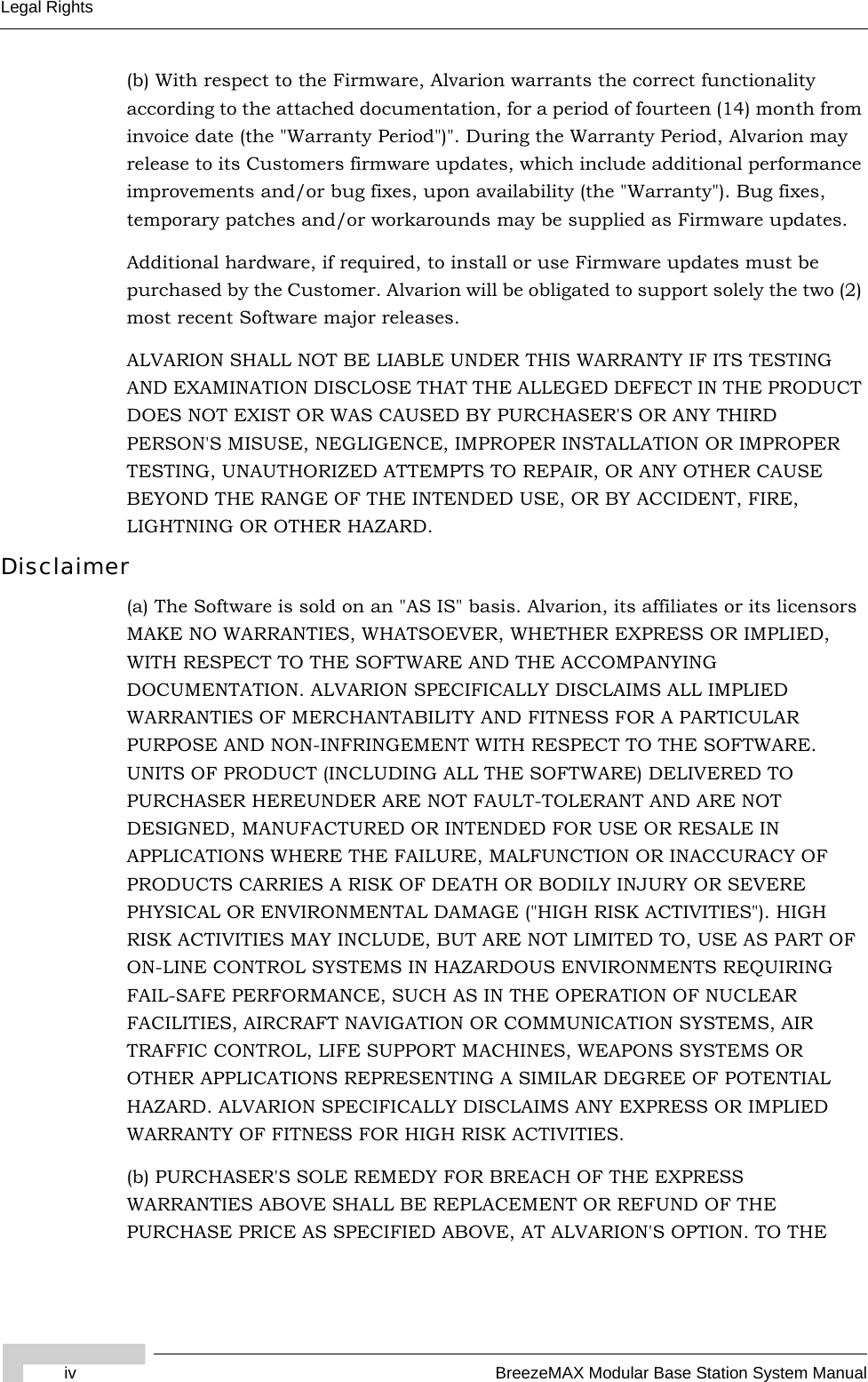
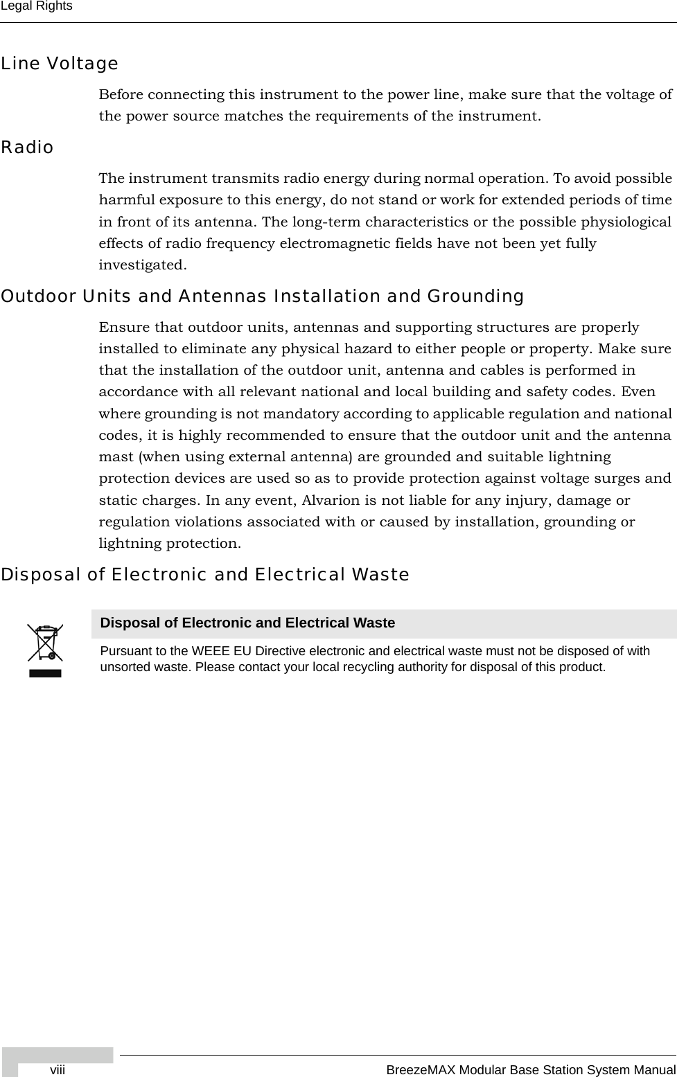
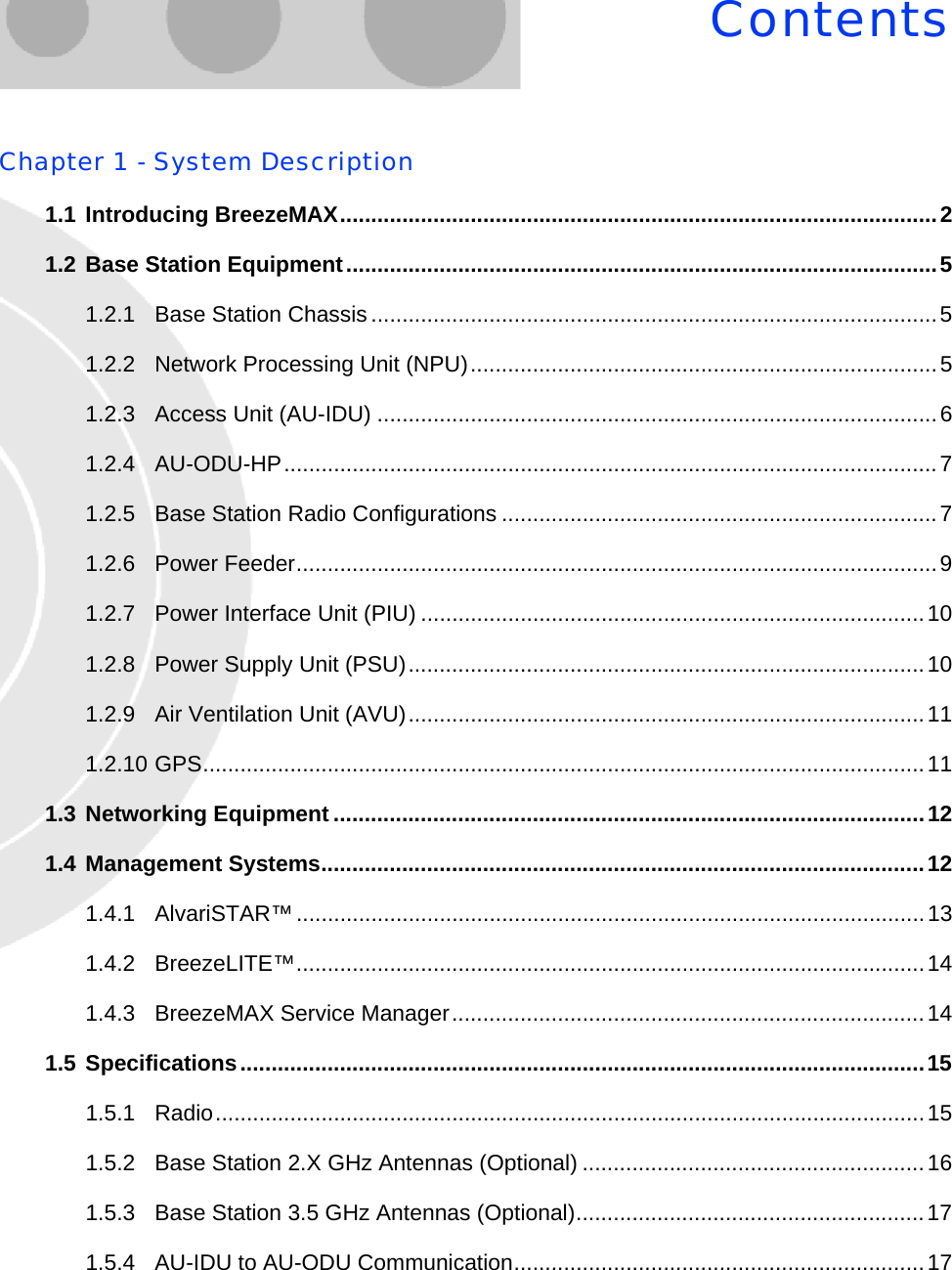
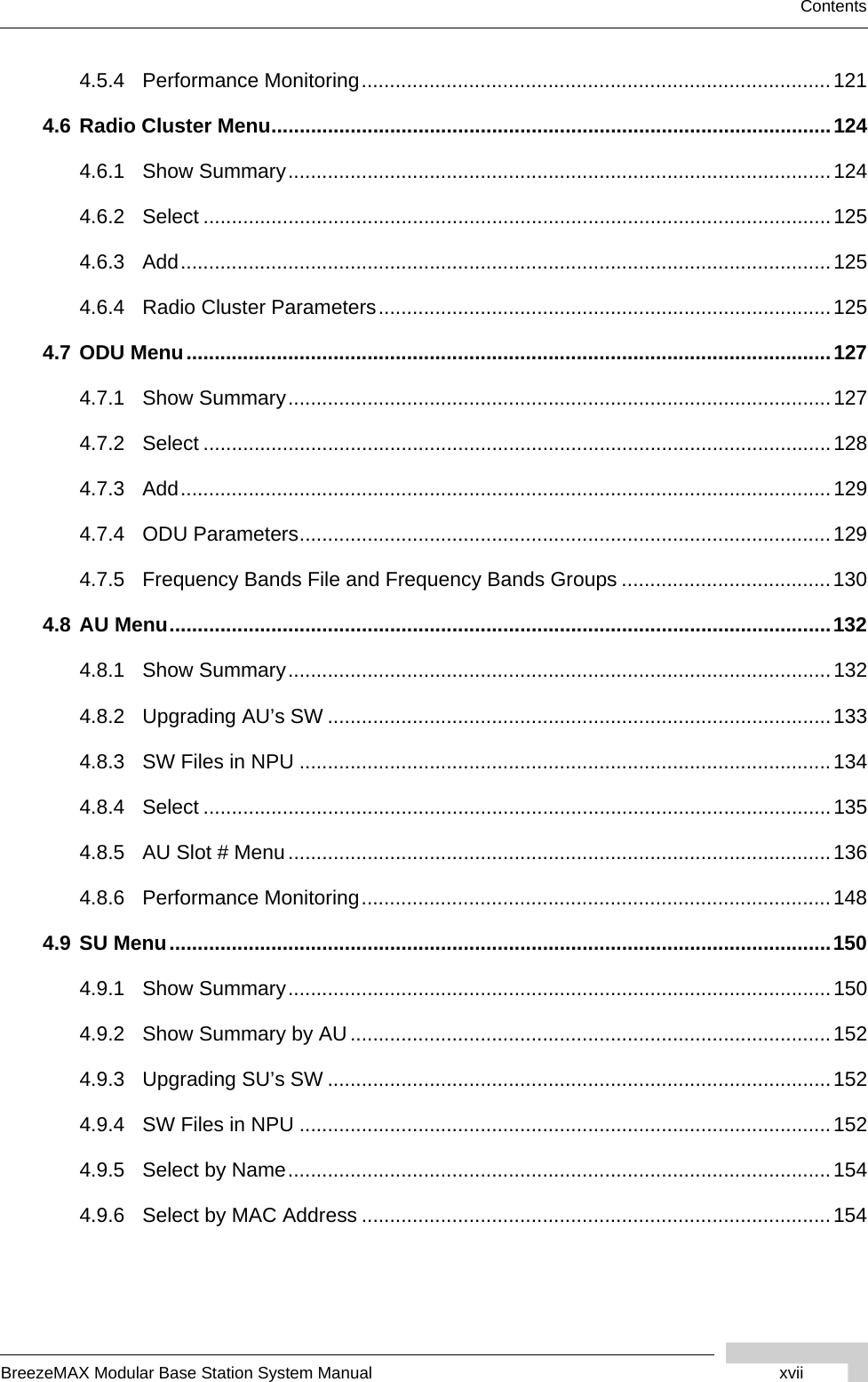
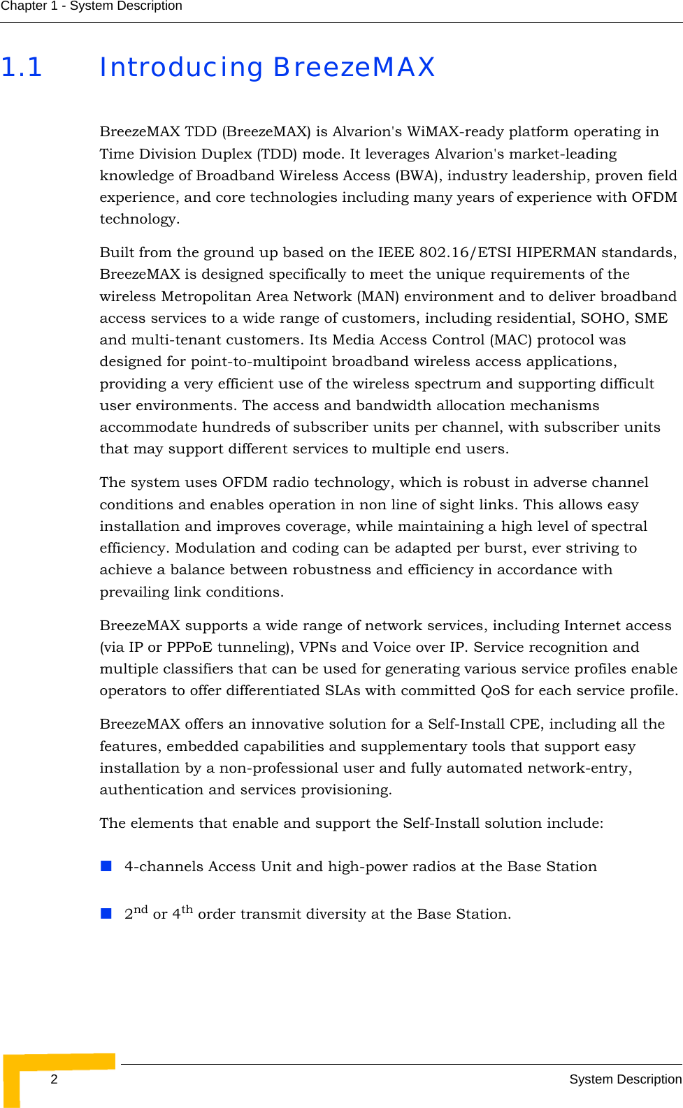
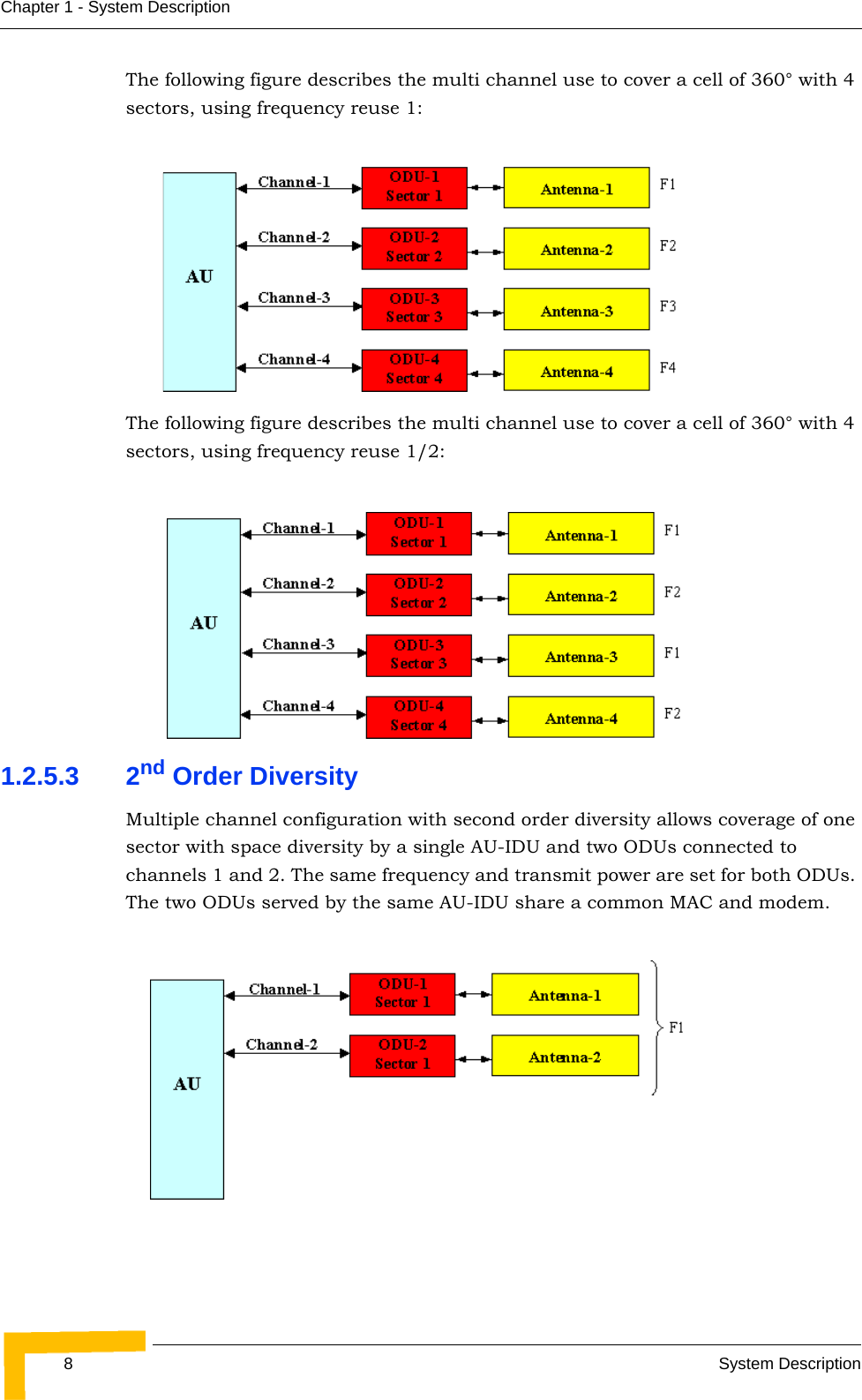
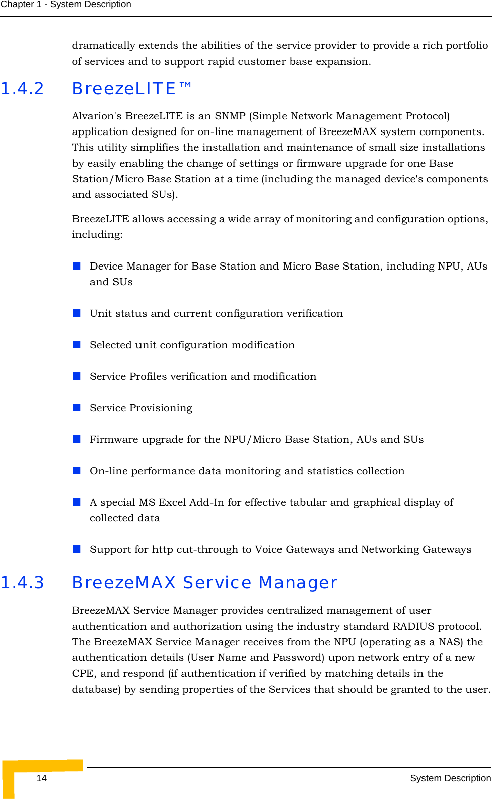
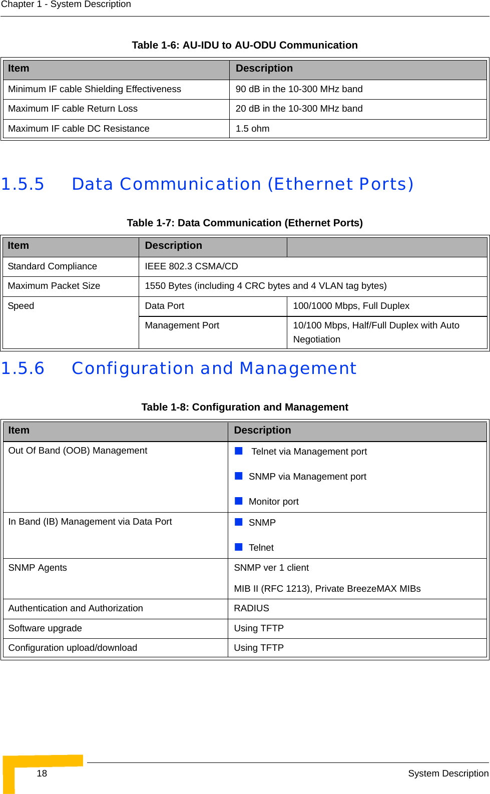
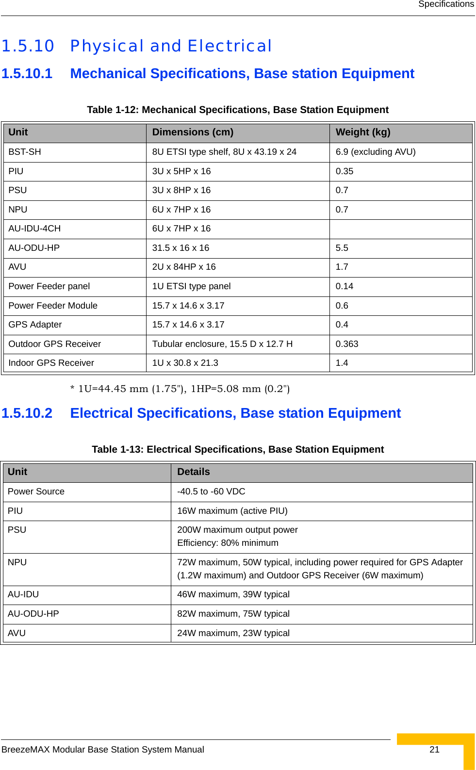
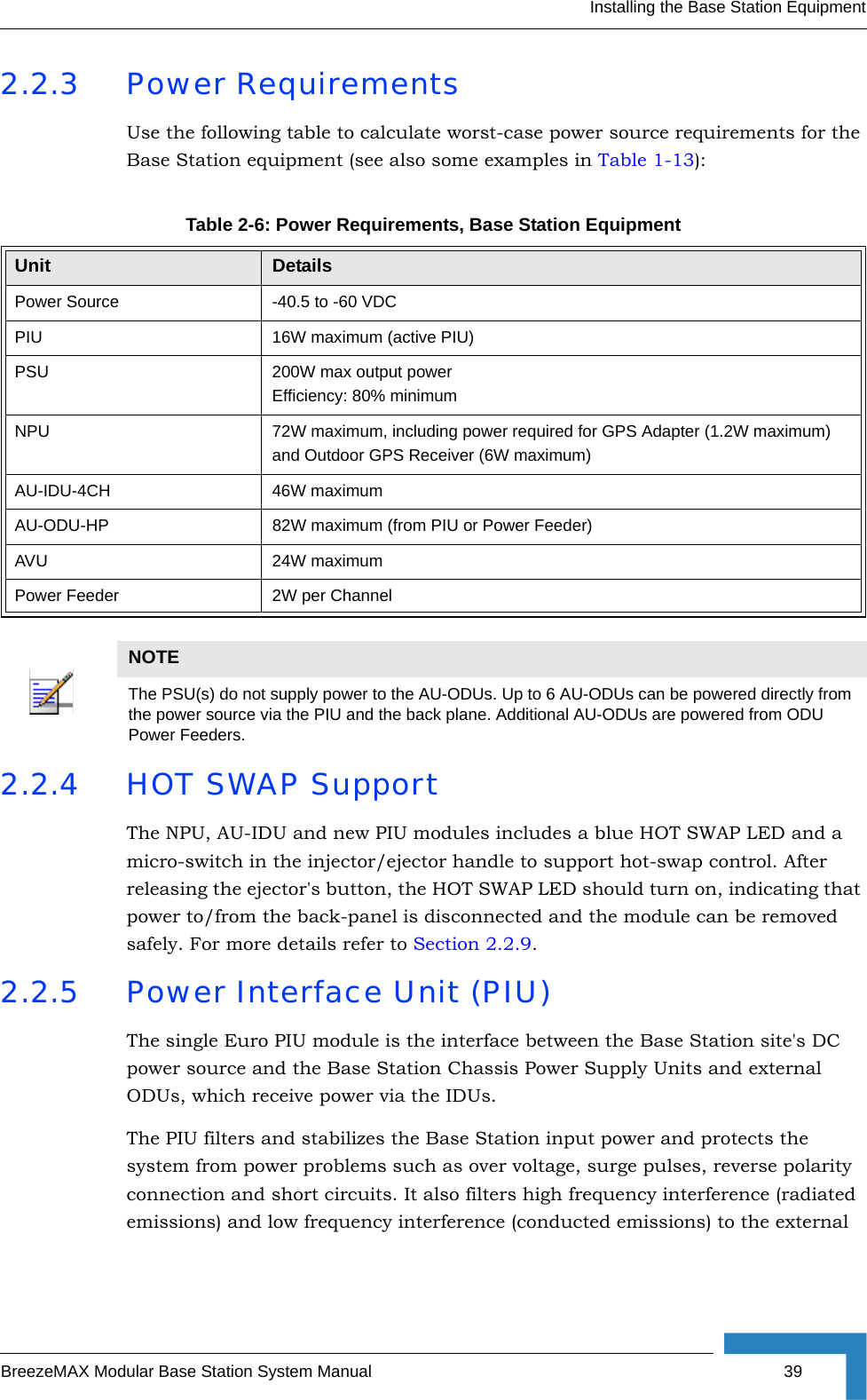
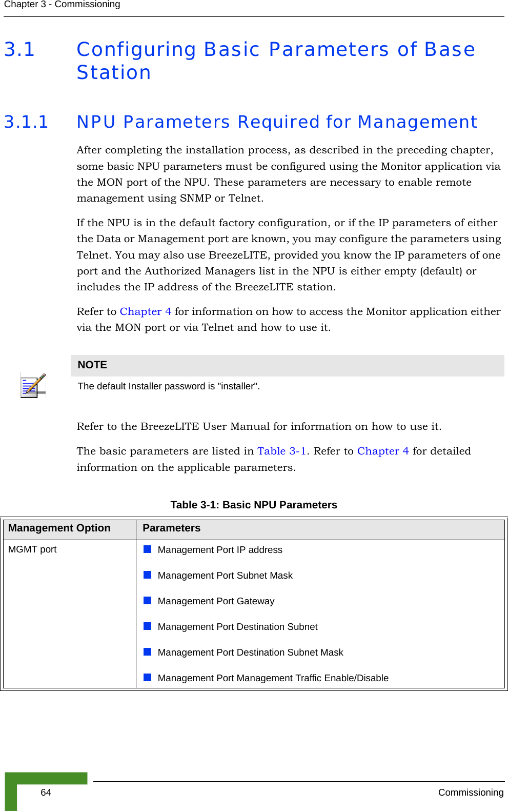
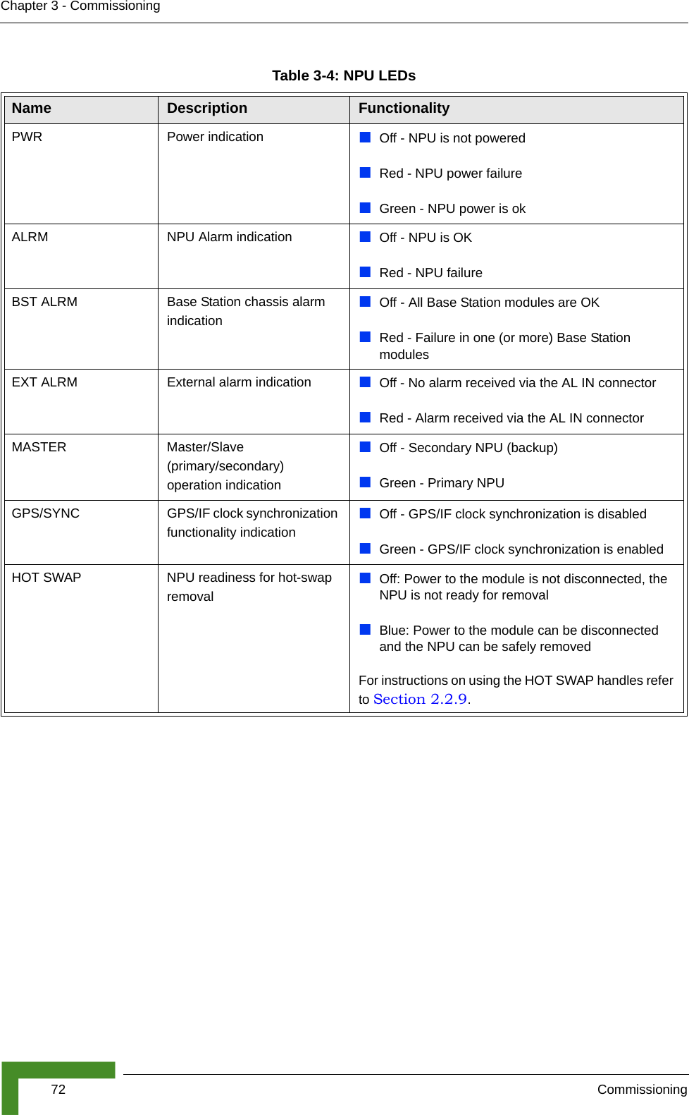

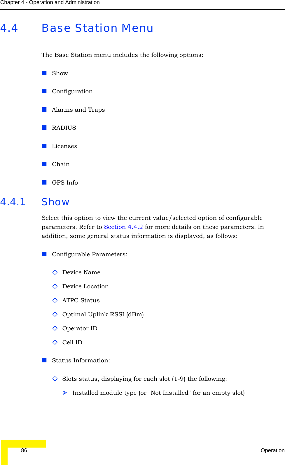

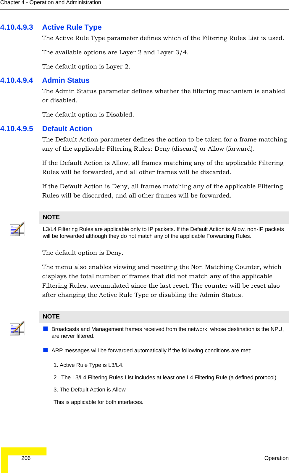
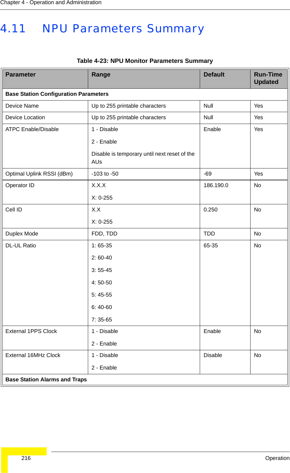
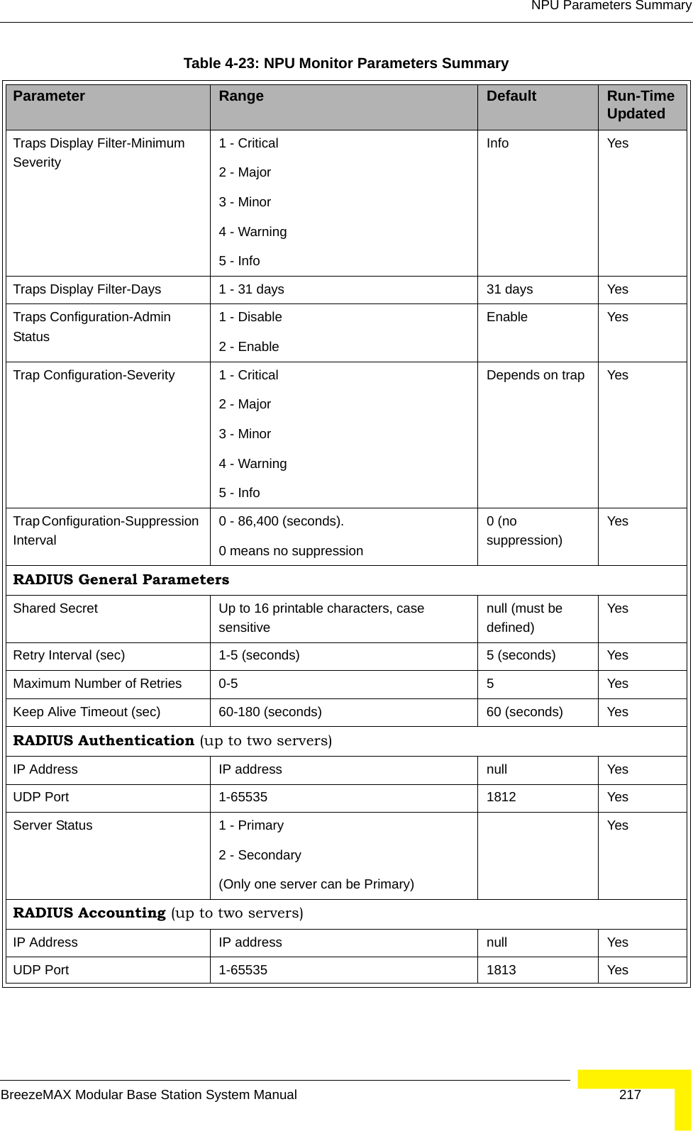
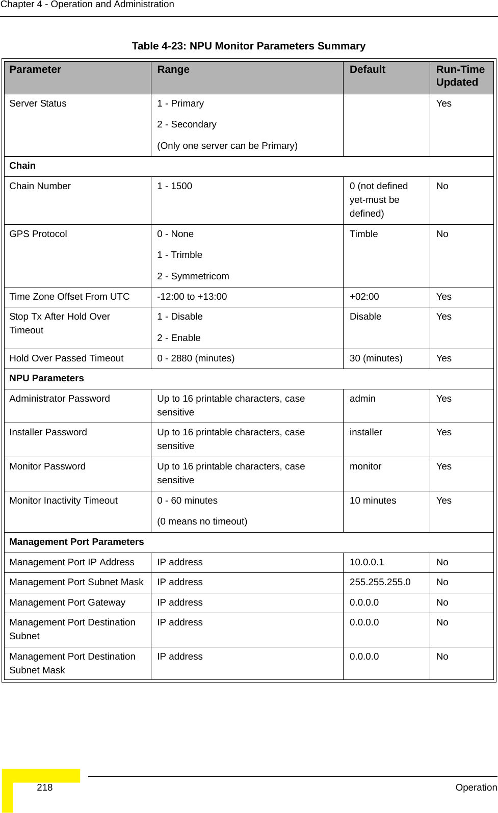
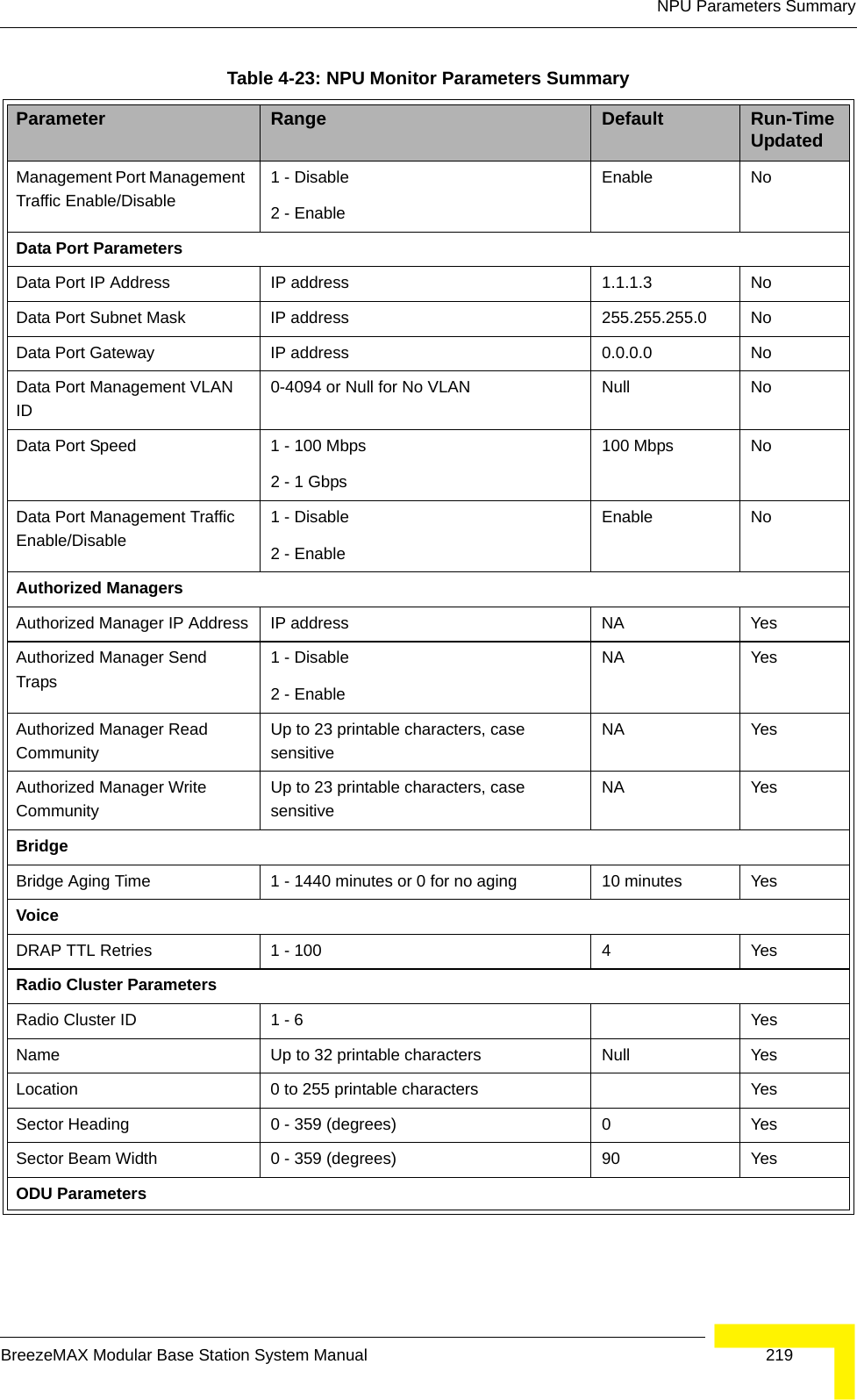
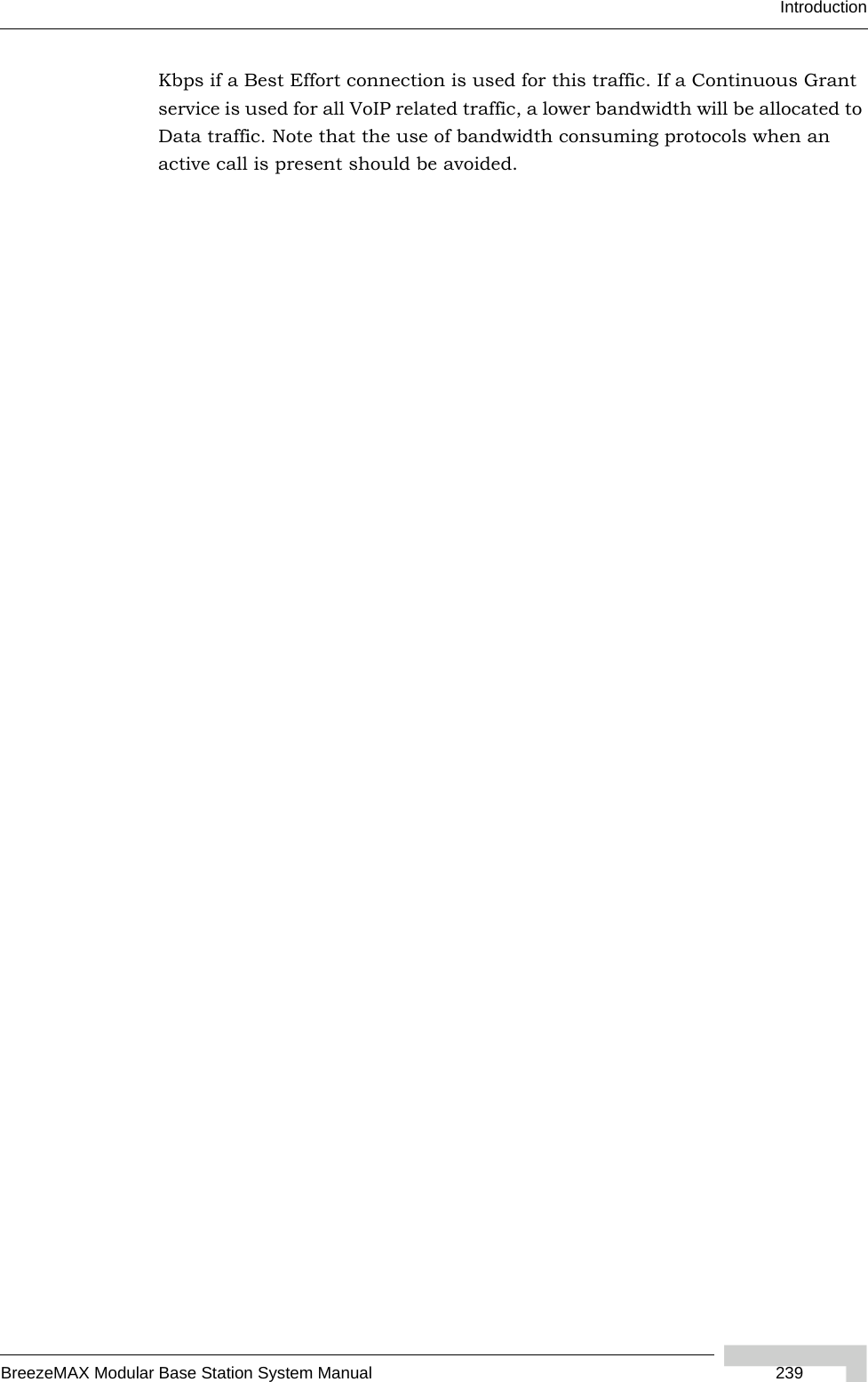
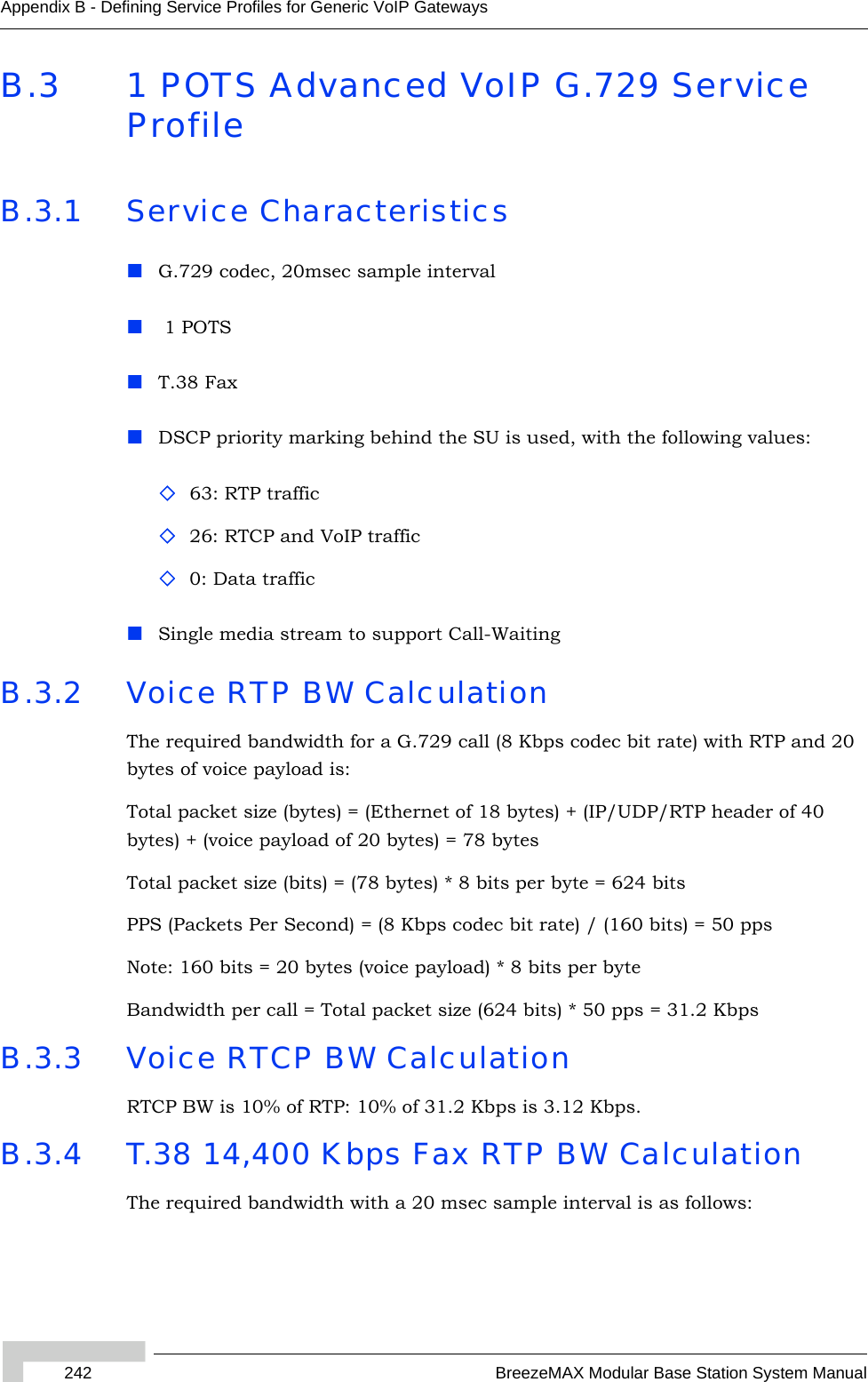
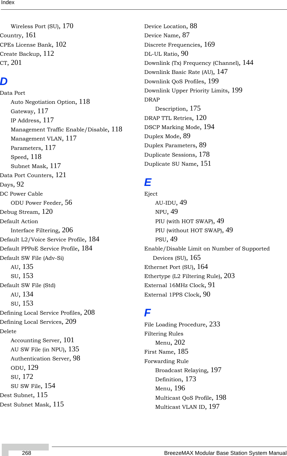
![168 OperationChapter 4 - Operation and AdministrationThe “main” frequencies are defined by the Start Frequency and Main Step, using the formula F(N) =Start Frequency + N*Main Step (F(0) = Start Frequency, F(1) = Start Frequency + Main Step,...). End Frequency is the upper limit.The Intermediate Step Mask can be used to define additional frequencies using a finer resolution. The Intermediate Step Mask includes up to 8 entries that include numbers from 1 to 8 (or none). The intermediate steps are defined as follows:For example, the Scan step Mask 1,2,5 means that the scanned frequencies are: Start Frequency, Start Frequency + 125 KHz, Start Frequency + 500 KHz, Start Frequency +N*Main Step, Start Frequency +N*Main Step + 125 KHz, Start Frequency +N*Main Step + 500 KHz (N=1, 2,...). End Frequency is the upper limit for the scanned frequencies).The Frequency Scanning menu includes the following options:4.9.7.3.11.1 ShowThe Show option enables viewing the following:Start Rx FrequencyTable 4-6: Intermediate Step MaskNumber included in Mask Effect on scanned frequencies setNone Only Start Frequency + N*Main Step [F(1), F(2)....F(N)]1 Start Frequency, Start Frequency + N*Main Step [F(0)F(1), F(2)....F(N)]2 Start Frequency + N*Main Step + 125 KHz (Start + 125 KHz is scanned only if 1 is included in mask)3 Start Frequency + N*Main Step + 250 KHz (Start + 250 KHz is scanned only if 1 is included in mask)4 Start Frequency + N*Main Step + 375 KHz (Start + 375 KHz is scanned only if 1 is included in mask)5 Start Frequency + N*Main Step + 500 KHz (Start + 500 KHz is scanned only if 1 is included in mask)6 Start Frequency + N*Main Step + 625 KHz (Start + 625 KHz is scanned only if 1 is included in mask)7 Start Frequency + N*Main Step + 750 KHz (Start + 750 KHz is scanned only if 1 is included in mask)8 For a bandwidth of 3.5 MHz: Start Frequency + N*Main Step + 875 KHz (Start + 875 KHz is scanned only if 1 is included in mask)For a bandwidth of 5 MHz: Start Frequency + N*Main Step + 1250 KHz (Start + 1250 KHz is scanned only if 1 is included in mask)](https://usermanual.wiki/Alvarion-Technologies/BMAX-BA23.User-Manual/User-Guide-719470-Page-194.png)
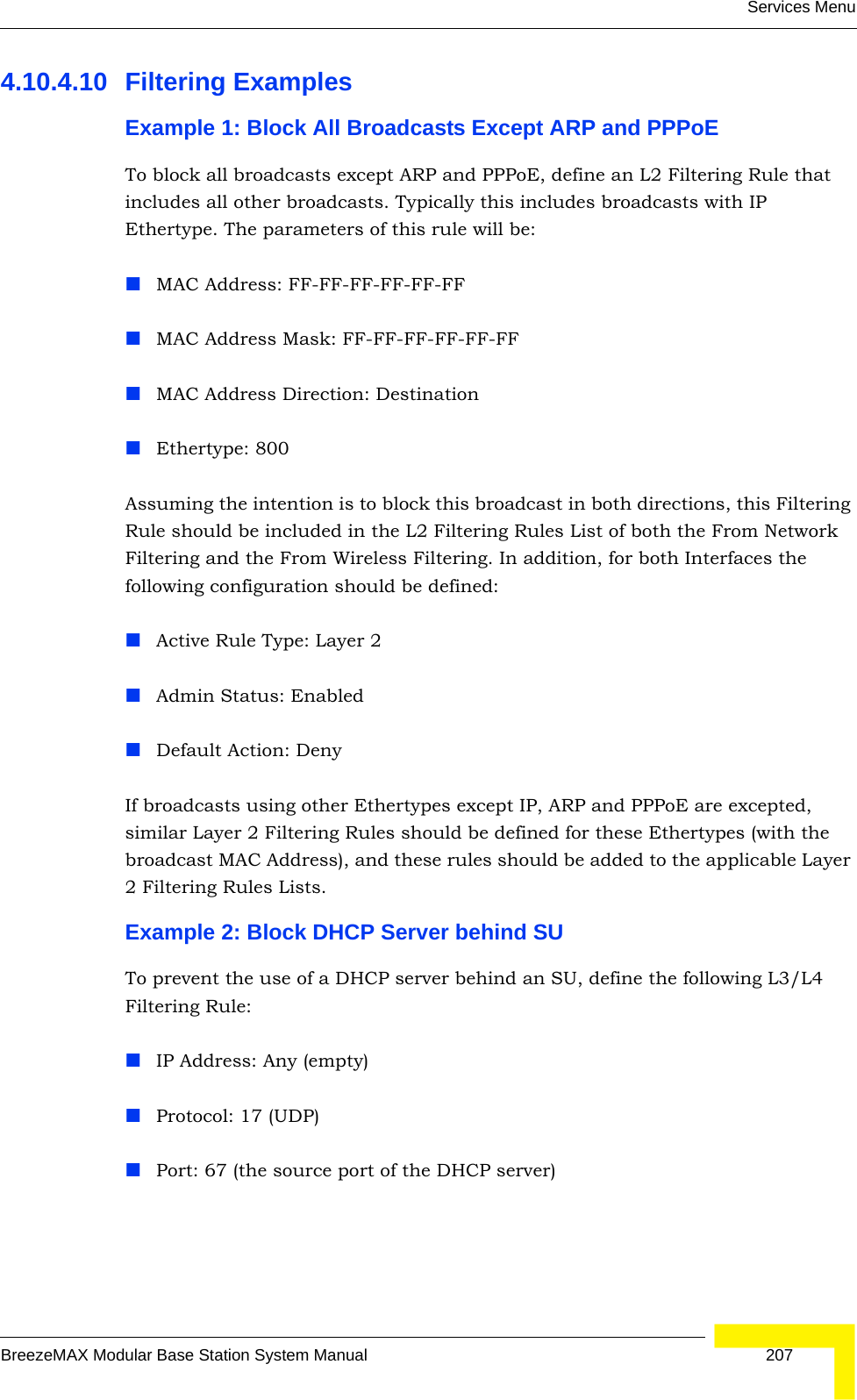
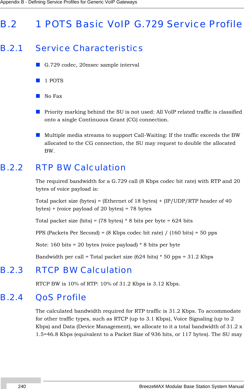
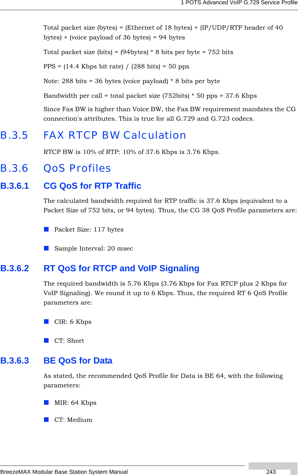
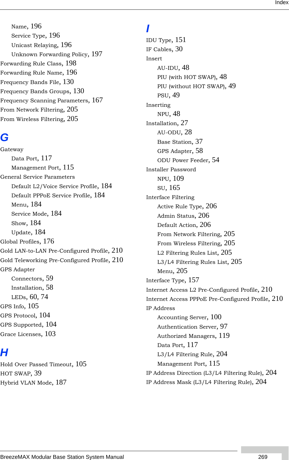
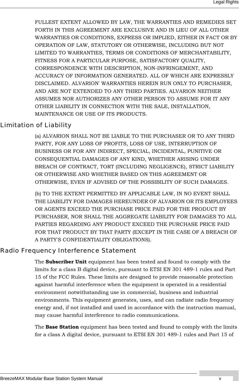
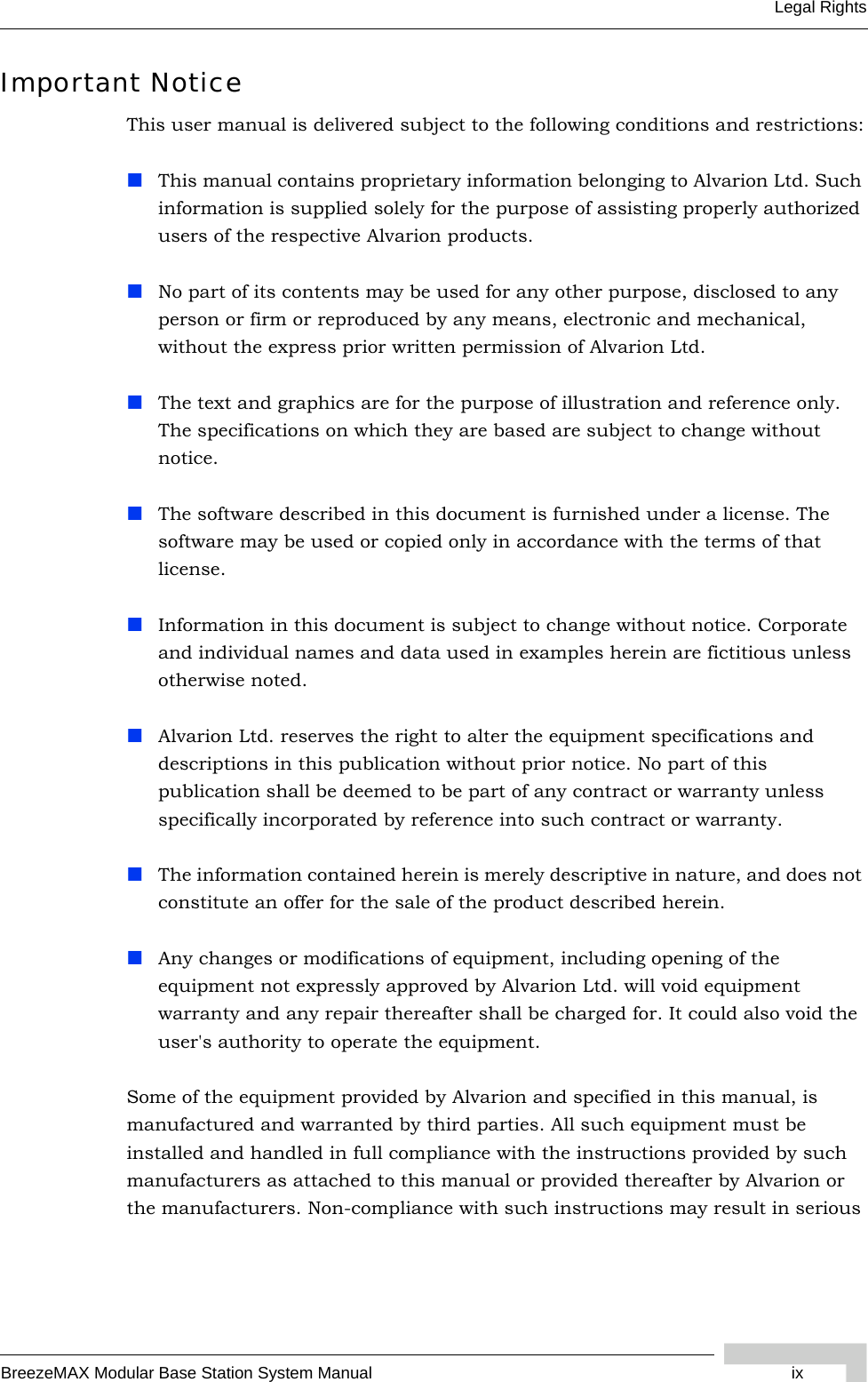
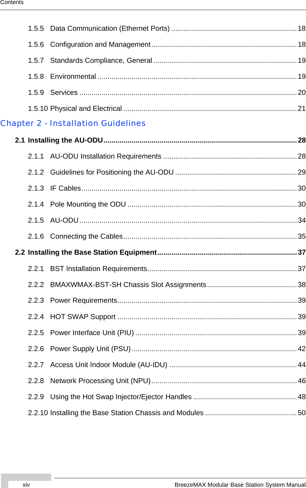
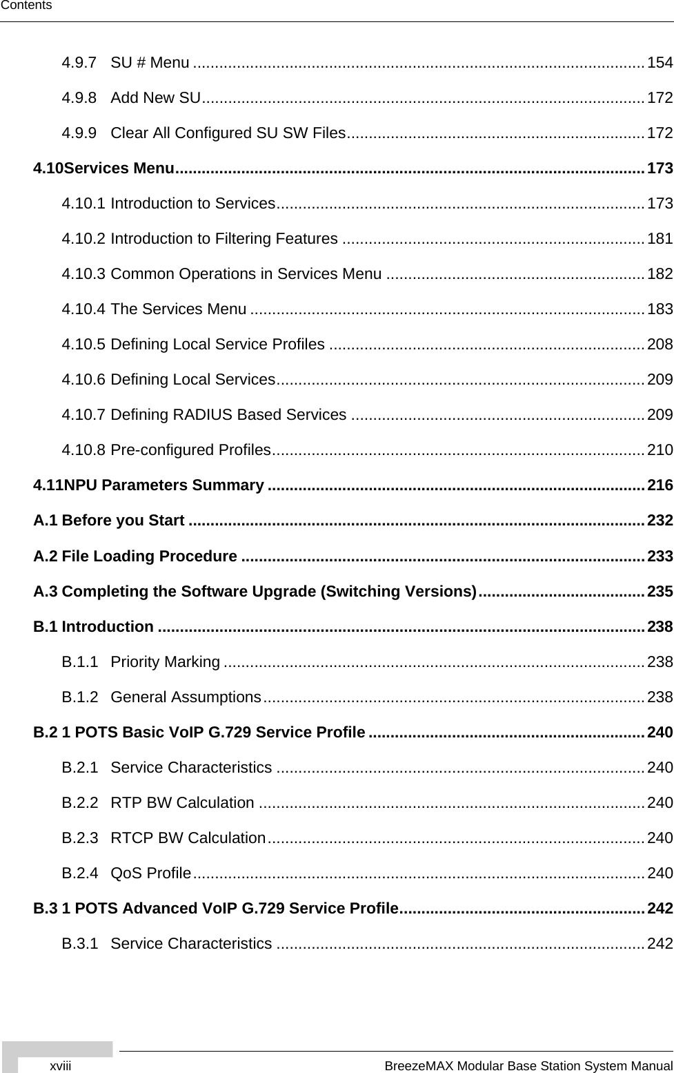
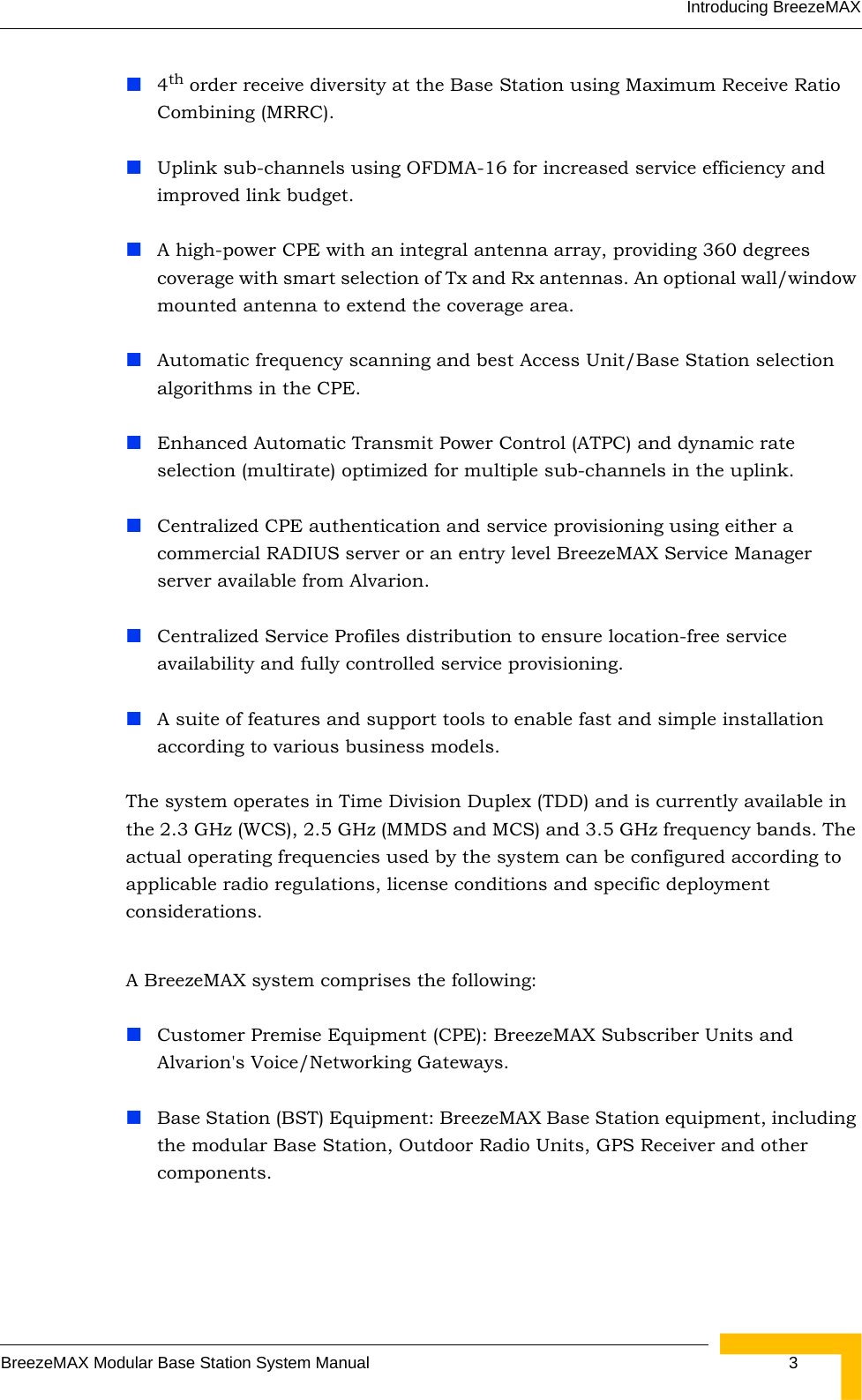
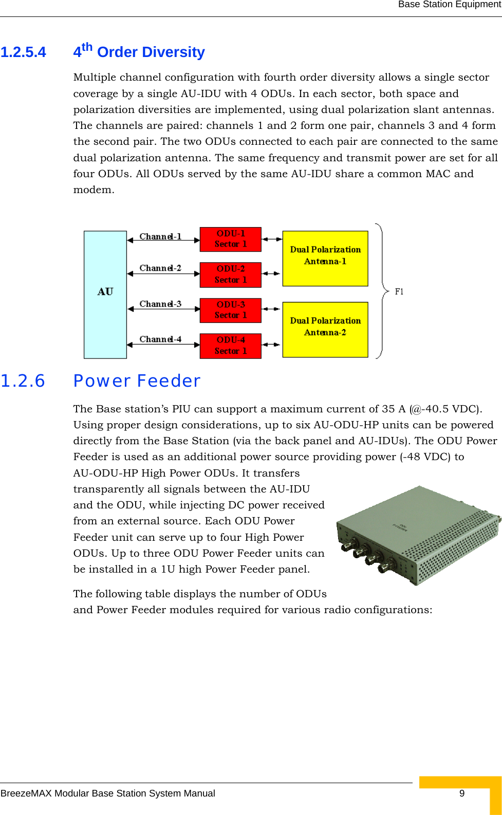
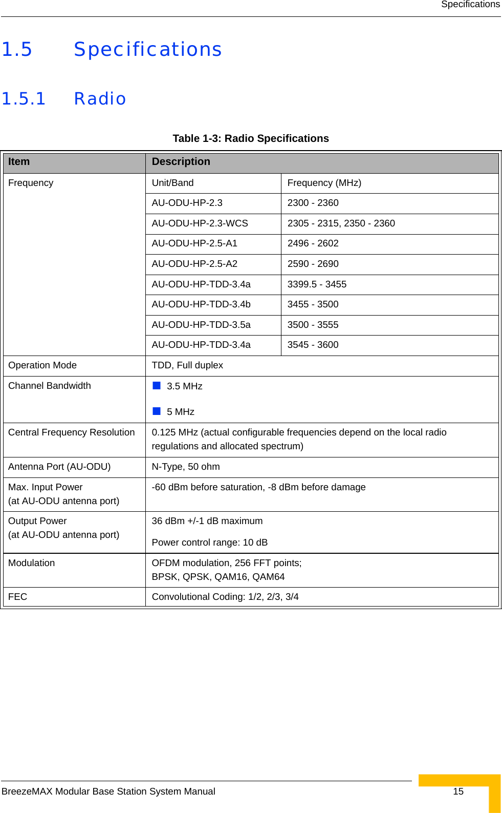
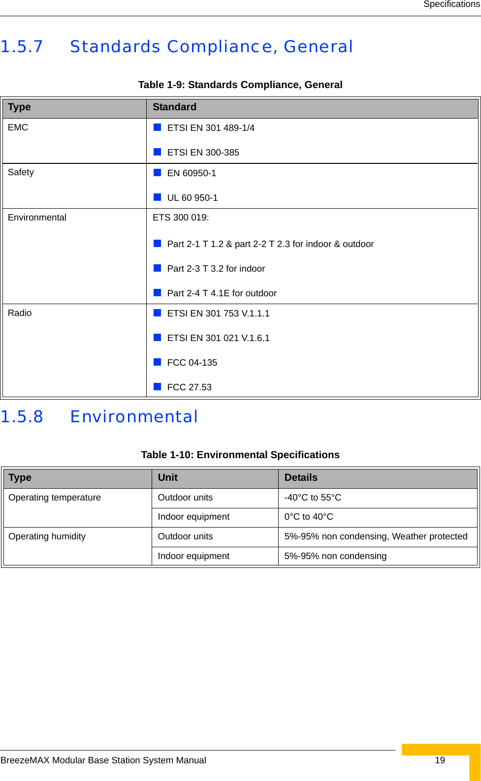
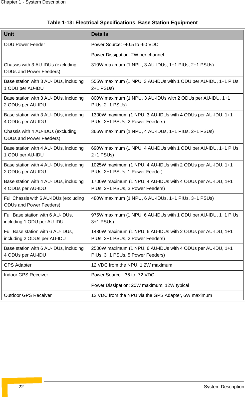
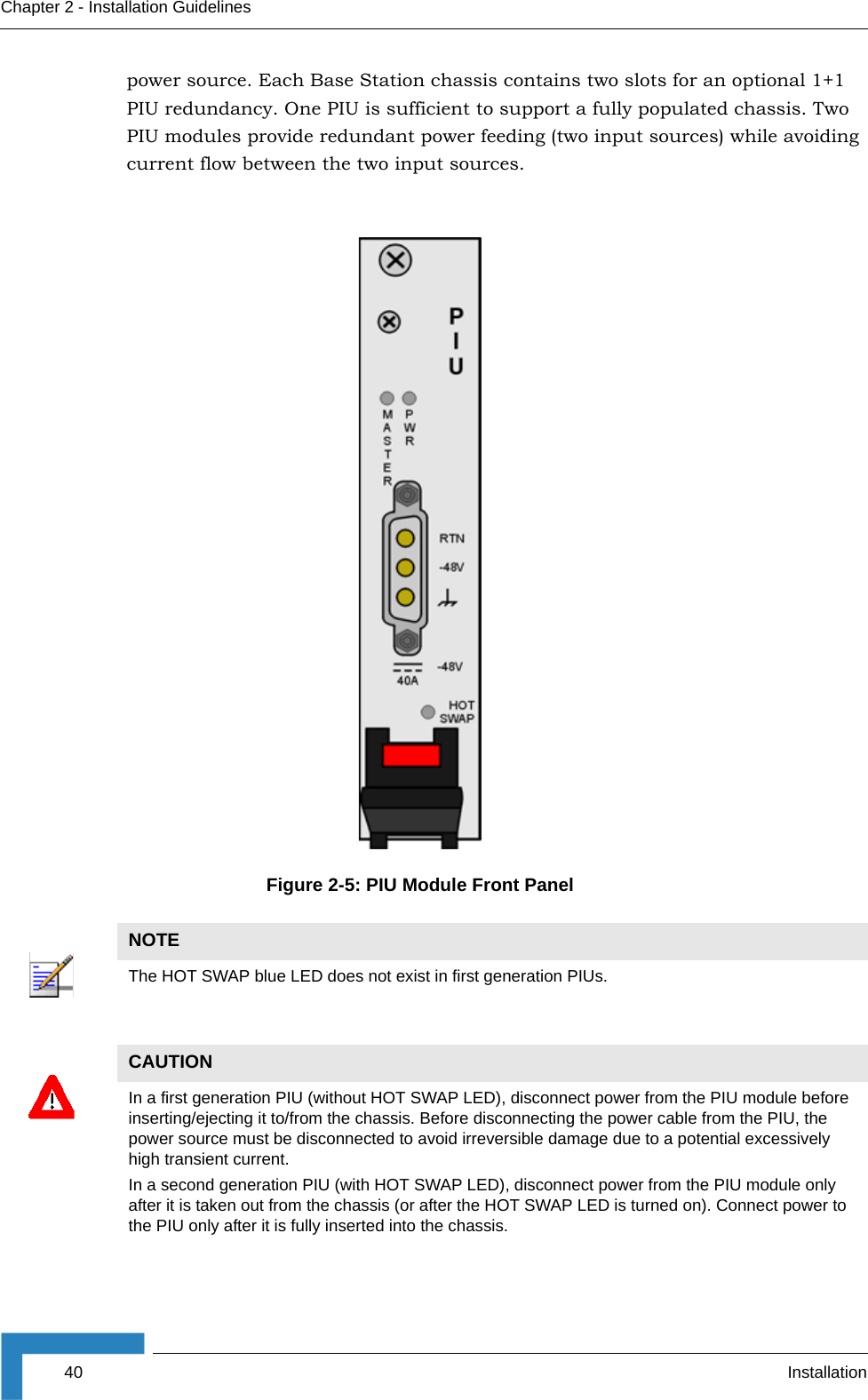
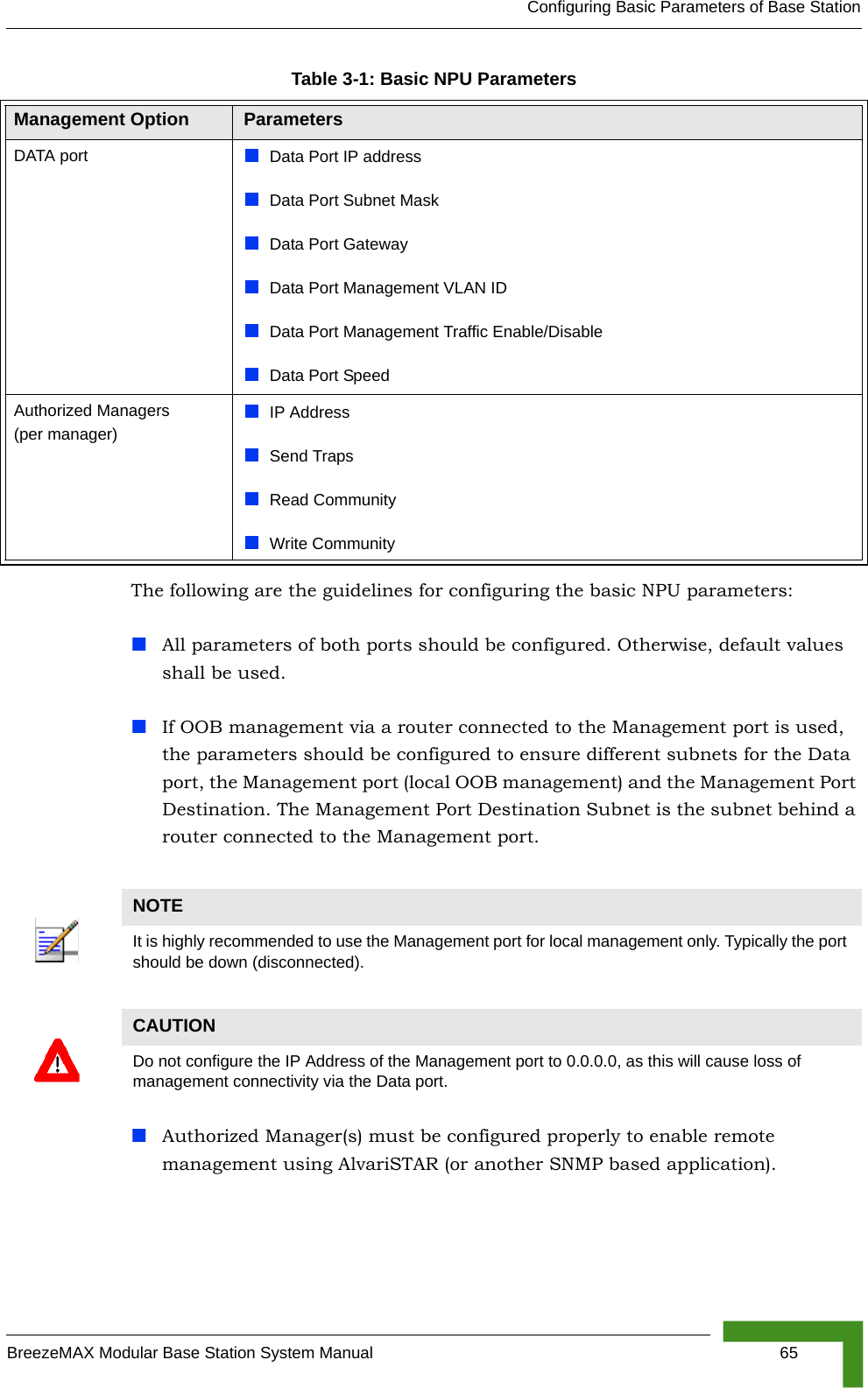
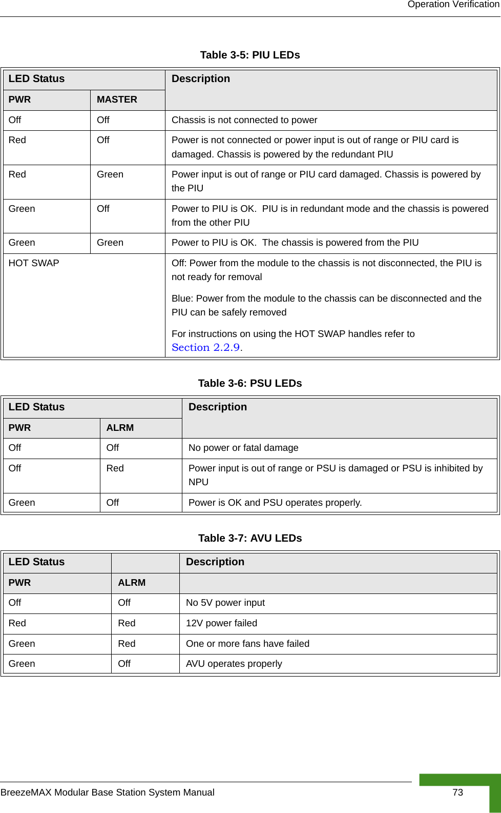
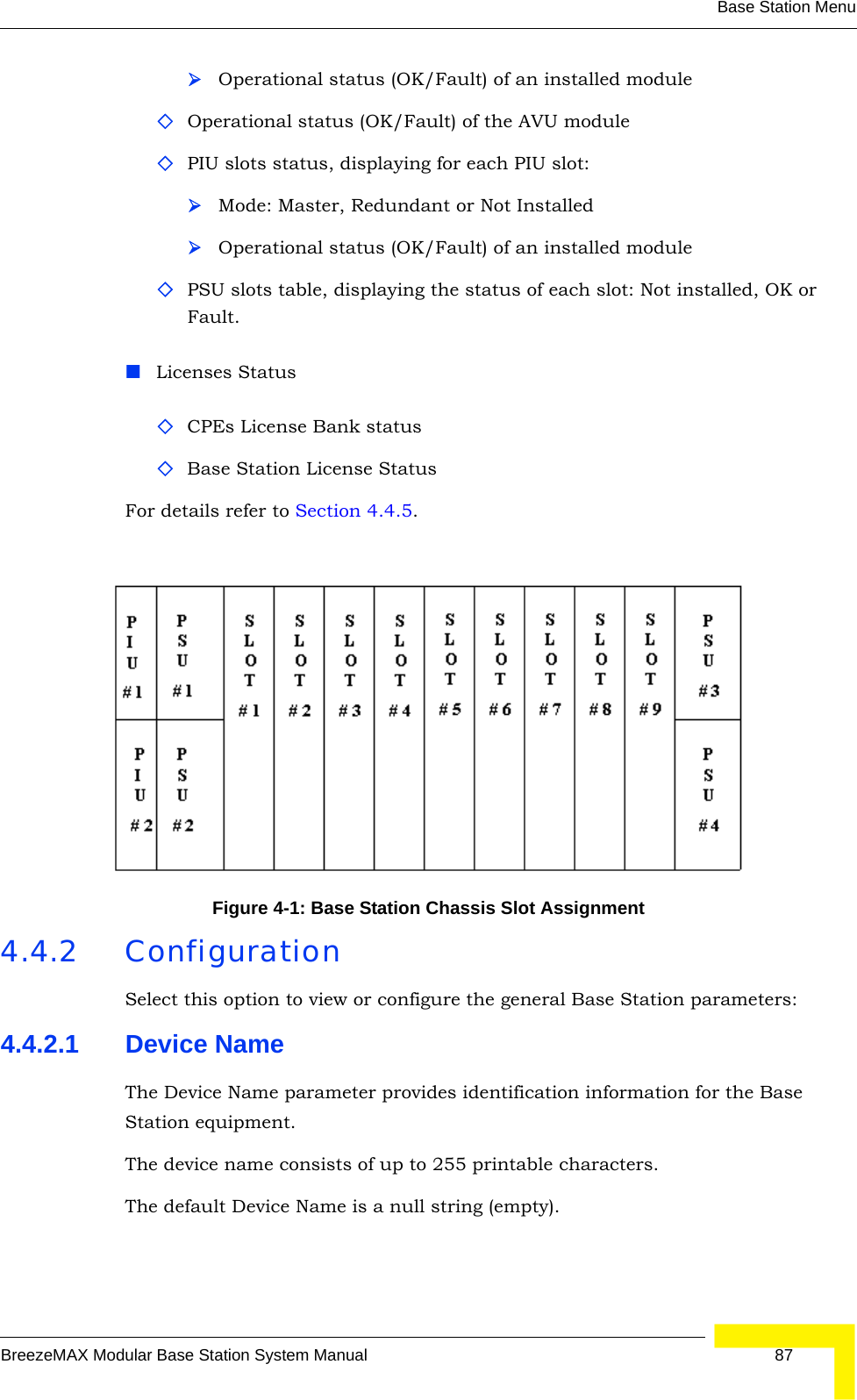
![Services MenuBreezeMAX Modular Base Station System Manual 1992 - 802.1p4.10.4.6.3 Uplink Upper Priority LimitsThe Uplink Upper Priority Limits parameter enables to define up to four ranges, where each range may be assigned a different QoS Profile for uplink communication. The list includes up to 4 numbers separated by commas, where each number must be higher than its predecessor and the last number must be the highest available for the applicable priority type (7 for 802.1p, 63 for DSCP).Examples for acceptable lists:DSCP Priority: [10,30,50,63]; [21,42,63]; [20,63]; [63].802.1p Priority: [2,4,6,7]; [1,5,7]; [6,7]; [7].A ranges list of 21,42,63 means that packets with a priority from 0 to 21 will be transmitted using the first QoS Profile defined in the Uplink QoS Profiles list (see below), packets with a priority from 22 to 42 will be transmitted using the second QoS Profile defined in the Uplink QoS Profiles list and packets with a priority higher than 42 (43 63) will be transmitted using the third Uplink QoS Profile.A ranges list that includes a single entry (63 for DSCP and 7 for 802.1p) means that priority based classification is not used.4.10.4.6.4 Uplink QoS ProfilesThe Uplink QoS Profiles parameter enables to define up to four QoS Profiles, where each entry is the QoS Profile associated with the applicable entry in the Uplink Upper Priority Limits list. The list includes up to four QoS Profile Names, where each name must be one of the names that exist in the database after being defined using the QoS Profile menu. Each entry in the Uplink QoS Profiles list is associated with the applicable entry in the Uplink Priority Ranges list.4.10.4.6.5 Downlink Upper Priority LimitsThe DownLink Upper Priority Limits list functionality is the same as that of the Uplink Upper Priority Limits list, except that the ranges are defined for downlink communication.4.10.4.6.6 Downlink QoS ProfilesThe Downlink QoS Profiles list functionality is the same as that of the Uplink QoS Profiles list, except that the QoS Profiles are associated with the entries in the Downlink Upper Priority Limits list.4.10.4.6.7 Priority Classifier ClassA read-only parameter (available only in Show menu) indicating whether the Priority Classifier is Local or Global. Global Priority Classifiers cannot be either updated or deleted.](https://usermanual.wiki/Alvarion-Technologies/BMAX-BA23.User-Manual/User-Guide-719470-Page-225.png)