Alvarion Technologies BMAX-BA36 BreezeMax 3.6 Broadband Wireless Access System User Manual BreezeMAX TDD BST System Manual
Alvarion Technologies Ltd. BreezeMax 3.6 Broadband Wireless Access System BreezeMAX TDD BST System Manual
user manual

BreezeMAX™ TDD Modular Base
Station System Manual
SW Version 4.5
January 2008
P/N

ii BreezeMAX Modular Base Station System Manual
Document History
Document History
Topic Description Version/Date
Issued
First Release New Product Manual SW Version
4.0.1, October
2006
Output power range of
2.x GHz AU-ODUs. Section 1.5.1,
Section 2.1, Section 4.8.4.4
Control range of new 2.x GHz
AU-ODU units (HC08 version
137) is 30 - 36 dBm. If diversity
is used, all ODUs connected to
the same AU-IDU must use the
same HC08 version.
SW Version 4.0.2
December 2006
Available AU-ODU units
Section 1.5.1, Section 1.5.10.1
Section 2.1.1.1
Added
AU-ODU-HP-2.3-Extended WCS
SW Version 4.0.2
December 2006
Optimal Uplink RSSI
Section 4.5.2.4.2
Updated range and default
value. In version 4.0.2 this
parameter is not updated in
run-time (reset required)
SW Version 4.0.2
December 2006
DL-UL Ratio
Section 4.5.2.6.2,
Updated combinations of
Sub-Channelizations,
Bandwidth, AU Service Type
and Maximum Cell Radius for
which certain DL-UL Ratios are
not available
SW Version 4.0.2
December 2006
Rate BPSK 3/4 removed
Section 1.5.1, Section 4.9.5.3.4,
Section 4.10.7.3.4
Rate BPSK 3/4 is not available
in TDD systems (according to
standard)
SW Version 4.0.2
December 2006
ARQ Enable/Disable
Section 4.9.5.3.1.2
In the current release ARQ
should not be enabled
SW Version 4.0.2
December 2006
AU Service Type
Section 4.9.5.3.5.2
New parameter SW Version 4.0.2
December 2006
SU MAC Parameters
Section 4.10.7.3.2
Changed functionality SW Version 4.0.2
December 2006
SU Phy Parameters
Section 4.10.7.3.3
Changed functionality SW Version 4.0.2
December 2006

BreezeMAX Modular Base Station System Manual iii
Document History
Best BST/AU Parameters
Section 4.10.7.3.10
Updated explanations. Added
Best BST/AU ID and Best
BST/AU ID Mask (replace Base
Station ID and Base Station ID
Mask in the SU MAC menu that
starting from this version will
not be applicable for units
operating in TDD/Advanced Si
mode).
SW Version 4.0.2
December 2006
Radio Parameters
Section 4.10.7.3.11
Updated explanations. Added
Bandwidth (replace the
Bandwidth parameter in the SU
Phy menu that starting from
this version will not be
applicable for units operating in
TDD/Advanced Si mode).
SW Version 4.0.2
December 2006
NPU Parameters Summary
Section 4.12
Updated to reflect all changes SW Version 4.0.2
December 2006
High-Power PIU
Section 1.2.6, Section 1.2.7,
Section 1.5.10.2, Section 1.5.10.3,
Section 2.2.3, Section 2.2.5,
Section 4.5.1
Added new PIU type
(High-Power PIU)
SW Version 4.1
April 2007
Power Cable for High-Power PIU
Section 2.2.5.2
Added instruction for cable for
new PIU type
SW Version 4.1
April 2007
3.x GHz Antennas
Section 1.5.3, Section 1.5.10.5
BS ANT 90V/3.3-3.7 removed
from list of optional antennas
SW Version 4.1
April 2007
Maximum number of Data
Connections per SU
Section 1.5.9
Updated to 32 per direction SW Version 4.1
April 2007
ODU Operating Temperature
Section 1.5.7
Updated specifications of
Operating Temperature:
AU-ODU-HP-2.3-WCS: -52°C to
55°C
All other ODUs: -40°C to 55°C
SW Version 4.1
April 2007
Topic Description Version/Date
Issued

iv BreezeMAX Modular Base Station System Manual
Document History
3.3 GHz band
Section 1.1, Section 1.5.1,
Section 4.8.5
New frequency band SW Version 4.1
April 2007
IP address configuration
Section 4.3, Section 4.5.4.2.2.1,
Section 4.5.4.3.2.1, Section 4.6.3.1.1,
Section 4.6.3.1.3, Section 4.6.3.2.1,
Section 4.6.3.2.3, Section 4.6.3.3.3.1
Updated limitations SW Version 4.1
April 2007
Switching Mode
Section 1.1, Section 4.5.2.3,
Section 4.5.4, Section 4.6.3.5,
Section 4.9.3.2, Section 4.9.5.1,
Section 4.9.5.3.5.1, Section 4.10.1,
Section 4.10.4.2, Section 4.10.7.1,
Section 4.10.7.2.1, Section 4.10.7.3.2,
Section 4.10.7.3.3, Section 4.10.7.3.5,
New feature (IP CS Switching
Mode)
SW Version 4.1
April 2007
Optimal Uplink RSSI
Section 4.5.2.4.2, Section 4.9.5.1
Reset is not required. Actual
range in the AU is -80 to -74
dBm.
SW Version 4.1
April 2007
DL-UL Ratio
Section 4.5.2.6.2
Updated limitations when
sub-channelization is enabled
SW Version 4.1
April 2007
Synchronization menu
Section 4.5.2.7
Updated structure of the
Monitor
SW Version 4.1
April 2007
Licenses
Section 4.5.5
Updated feature description
(distinction between local and
permanent CPE licenses)
SW Version 4.1
April 2007
Show License Log
Section 4.5.5.4
New feature SW Version 4.1
April 2007
Create Backup
Section 4.6.2.5
New option: BS License File SW Version 4.1
April 2007
SU License
Section 4.10.7.3.9
Updated (Unit type affected by
license))
SW Version 4.1
April 2007
ODU - Show Summary
Section 4.8.1
Updated (Tx Power changed to
Configured Tx Power,
Associated to AU:Channel
added)
SW Version 4.1
April 2007
Topic Description Version/Date
Issued

BreezeMAX Modular Base Station System Manual v
Document History
ODU - Show (for a selected ODU)
Section 4.8.2.1
Updated (Tx Power changed to
Configured Tx Power,
Associated to AU:Channel and
Actual Tx Power added)
SW Version 4.1
April 2007
ARQ
Section 4.9.5.1, Section 4.9.5.3.1,
Section 4.9.5.3.4, Section 4.9.6.1
ARQ Enable/Disable and
counters applicable for ARQ
enabled transmissions has been
removed (in TDD system ARQ is
always disabled)
SW Version 4.1
April 2007
AU Unit Control-Show Versions
Section 4.9.5.2.3.1
Updated (Configured AU/SU SW
Files added)
SW Version 4.1
April 2007
Actual Maximum Cell Radius
Section 4.9.5.3.1.2
New read-only parameter SW Version 4.1
April 2007
AU Multi-Channel - Show Summary
Section 4.9.5.3.3.1
Tx Power changed to Configured
Tx Power
SW Version 4.1
April 2007
Diversity Mode
Section 4.9.5.3.3.2
New Fourth Order Diversity
modes
SW Version 4.1
April 2007
Full Sub-Channelization (OFDMA)
support
Section 4.9.5.3.4, Section 4.5.2.4
Updated description of the
Multirate algorithm and its
parameters. Updated
description of ATPC algorithm.
SW Version 4.1
April 2007
AU Minimum Allocation
Section 4.9.5.3.5.2
Updated parameter’s name and
options
SW Version 4.1
April 2007
AU Ports Counters
Section 4.9.6.1
Back-Panel changed to Back
Plane
SW Version 4.1
April 2007
BER Test
Section 4.9.6.2
New feature SW Version 4.1
April 2007
Selected SU Show menu
Section 4.10.7.1
Updated SW Version 4.1
April 2007
Antennas Specifications
Sections 1.5.2, 1.5.3, 1.5.10.4,
1.5.10.5
Updated SW Version 4.1
July 2007
Replacing a PIU
Section 2.2.12.4
New SW Version 4.1
July 2007
Topic Description Version/Date
Issued

vi BreezeMAX Modular Base Station System Manual
Document History
CT in BE QoS
Sections 4.11.4.7, 4.11.4.7.3,
Table 4-14, Table 4-19, Table 4-22,
Table 4-23, Sections B.3.6.3, B.5.6.3
CT in BE QoS is not
configurable (set to Short)
SW Version 4.1
July 2007
Ber Test
Section 4.9.6.2
BER Test feature is not
supported in current version
SW Version 4.1
July 2007
RADIUS description
Section 4.5.4
Added detailed description of
SU authentication process
SW Version 4.1
July 2007
Minimum Number of Sub-Channels
Section 4.9.5.3.4.3,
Default updated to 1 SW Version 4.1
July 2007
Antennas Specifications
Sections 1.5.2 1.5.3
All antennas complies with ETSI
EN 302 326-3 V1.2.1
SW Version 4.1
July 2007
Sensitivity
Section 1.5.1
Updated SW Version 4.1
July 2007
Forwarding Rule selection in Service
Profile
Section 4.11.4.4.7
Updated description: L2
Forwarding Rule can be used in
a VoIP Service Profile, and vice
versa
SW Version 4.1
July 2007
Unicast Relaying
Section 4.11.4.5.3
Updated description: Applicable
only for L2 Forwarding Rules.
Added defaults for VoIP and
PPPoE Forwarding Rules.
SW Version 4.1
July 2007
Broadcast Relaying
Section 4.11.4.5.4
Updated description: Applicable
only for L2 Forwarding Rules.
Added defaults for VoIP and
PPPoE Forwarding Rules.
SW Version 4.1
July 2007
Unknown Forwarding Policy
Section 4.11.4.5.5
Updated description: Applicable
only for L2 Forwarding Rules.
Added defaults for VoIP and
PPPoE Forwarding Rules.
SW Version 4.1
July 2007
VoIP Services Updated names: Voice Service
Type changed to VoIP Service
Type
SW Version 4.1
July 2007
Deleting an SU from the database
Section 4.10.7.6
Update description: only
disconnected SUs can be
deleted.
SW Version 4.1
July 2007
Topic Description Version/Date
Issued

BreezeMAX Modular Base Station System Manual vii
Document History
Forwarding Rules functionality
Section 4.11.1.1
Updated description SW Version 4.1
July 2007
L2, PPPoE and VoIP Services
functionality
Section 4.11.1.2
Updated descriptions SW Version 4.1
July 2007
NPU Parameters Summary
Section 4.12
Updated to reflect all changes SW Version 4.1
July 2007
Topic Description Version/Date
Issued

viii BreezeMAX Modular Base Station System Manual
Legal Rights
Legal Rights
© Copyright 2007 Alvarion Ltd. All rights reserved.
The material contained herein is proprietary, privileged, and confidential and
owned by Alvarion or its third party licensors. No disclosure thereof shall be made
to third parties without the express written permission of Alvarion Ltd.
Alvarion Ltd. reserves the right to alter the equipment specifications and
descriptions in this publication without prior notice. No part of this publication
shall be deemed to be part of any contract or warranty unless specifically
incorporated by reference into such contract or warranty.
Trade Names
Alvarion®, BreezeCOM®, WALKair®, WALKnet®, BreezeNET®, BreezeACCESS®,
BreezeMANAGE™, BreezeLINK®, BreezeCONFIG™, BreezeMAX™, AlvariSTAR™,
AlvariCRAFT™, BreezeLITE™, MGW™, eMGW™ and/or other products and/or
services referenced here in are either registered trademarks, trademarks or
service marks of Alvarion Ltd.
All other names are or may be the trademarks of their respective owners.
Statement of Conditions
The information contained in this manual is subject to change without notice.
Alvarion Ltd. shall not be liable for errors contained herein or for incidental or
consequential damages in connection with the furnishing, performance, or use of
this manual or equipment supplied with it.
Warranties and Disclaimers
All Alvarion Ltd. ("Alvarion") products purchased from Alvarion or through any of
Alvarion's authorized resellers are subject to the following warranty and product
liability terms and conditions.
Exclusive Warranty
(a) Alvarion warrants that the Product hardware it supplies and the tangible
media on which any software is installed, under normal use and conditions, will
be free from significant defects in materials and workmanship for a period of
fourteen (14) months from the date of shipment of a given Product to Purchaser
(the "Warranty Period"). Alvarion will, at its sole option and as Purchaser's sole
remedy, repair or replace any defective Product in accordance with Alvarion'
standard R&R procedure.
(b) With respect to the Firmware, Alvarion warrants the correct functionality
according to the attached documentation, for a period of fourteen (14) month from

BreezeMAX Modular Base Station System Manual ix
Legal Rights
invoice date (the "Warranty Period")". During the Warranty Period, Alvarion may
release to its Customers firmware updates, which include additional performance
improvements and/or bug fixes, upon availability (the "Warranty"). Bug fixes,
temporary patches and/or workarounds may be supplied as Firmware updates.
Additional hardware, if required, to install or use Firmware updates must be
purchased by the Customer. Alvarion will be obligated to support solely the two (2)
most recent Software major releases.
ALVARION SHALL NOT BE LIABLE UNDER THIS WARRANTY IF ITS TESTING
AND EXAMINATION DISCLOSE THAT THE ALLEGED DEFECT IN THE PRODUCT
DOES NOT EXIST OR WAS CAUSED BY PURCHASER'S OR ANY THIRD
PERSON'S MISUSE, NEGLIGENCE, IMPROPER INSTALLATION OR IMPROPER
TESTING, UNAUTHORIZED ATTEMPTS TO REPAIR, OR ANY OTHER CAUSE
BEYOND THE RANGE OF THE INTENDED USE, OR BY ACCIDENT, FIRE,
LIGHTNING OR OTHER HAZARD.
Disclaimer
(a) The Software is sold on an "AS IS" basis. Alvarion, its affiliates or its licensors
MAKE NO WARRANTIES, WHATSOEVER, WHETHER EXPRESS OR IMPLIED,
WITH RESPECT TO THE SOFTWARE AND THE ACCOMPANYING
DOCUMENTATION. ALVARION SPECIFICALLY DISCLAIMS ALL IMPLIED
WARRANTIES OF MERCHANTABILITY AND FITNESS FOR A PARTICULAR
PURPOSE AND NON-INFRINGEMENT WITH RESPECT TO THE SOFTWARE.
UNITS OF PRODUCT (INCLUDING ALL THE SOFTWARE) DELIVERED TO
PURCHASER HEREUNDER ARE NOT FAULT-TOLERANT AND ARE NOT
DESIGNED, MANUFACTURED OR INTENDED FOR USE OR RESALE IN
APPLICATIONS WHERE THE FAILURE, MALFUNCTION OR INACCURACY OF
PRODUCTS CARRIES A RISK OF DEATH OR BODILY INJURY OR SEVERE
PHYSICAL OR ENVIRONMENTAL DAMAGE ("HIGH RISK ACTIVITIES"). HIGH
RISK ACTIVITIES MAY INCLUDE, BUT ARE NOT LIMITED TO, USE AS PART OF
ON-LINE CONTROL SYSTEMS IN HAZARDOUS ENVIRONMENTS REQUIRING
FAIL-SAFE PERFORMANCE, SUCH AS IN THE OPERATION OF NUCLEAR
FACILITIES, AIRCRAFT NAVIGATION OR COMMUNICATION SYSTEMS, AIR
TRAFFIC CONTROL, LIFE SUPPORT MACHINES, WEAPONS SYSTEMS OR
OTHER APPLICATIONS REPRESENTING A SIMILAR DEGREE OF POTENTIAL
HAZARD. ALVARION SPECIFICALLY DISCLAIMS ANY EXPRESS OR IMPLIED
WARRANTY OF FITNESS FOR HIGH RISK ACTIVITIES.
(b) PURCHASER'S SOLE REMEDY FOR BREACH OF THE EXPRESS
WARRANTIES ABOVE SHALL BE REPLACEMENT OR REFUND OF THE
PURCHASE PRICE AS SPECIFIED ABOVE, AT ALVARION'S OPTION. TO THE
FULLEST EXTENT ALLOWED BY LAW, THE WARRANTIES AND REMEDIES SET
FORTH IN THIS AGREEMENT ARE EXCLUSIVE AND IN LIEU OF ALL OTHER

x BreezeMAX Modular Base Station System Manual
Legal Rights
WARRANTIES OR CONDITIONS, EXPRESS OR IMPLIED, EITHER IN FACT OR BY
OPERATION OF LAW, STATUTORY OR OTHERWISE, INCLUDING BUT NOT
LIMITED TO WARRANTIES, TERMS OR CONDITIONS OF MERCHANTABILITY,
FITNESS FOR A PARTICULAR PURPOSE, SATISFACTORY QUALITY,
CORRESPONDENCE WITH DESCRIPTION, NON-INFRINGEMENT, AND
ACCURACY OF INFORMATION GENERATED. ALL OF WHICH ARE EXPRESSLY
DISCLAIMED. ALVARION' WARRANTIES HEREIN RUN ONLY TO PURCHASER,
AND ARE NOT EXTENDED TO ANY THIRD PARTIES. ALVARION NEITHER
ASSUMES NOR AUTHORIZES ANY OTHER PERSON TO ASSUME FOR IT ANY
OTHER LIABILITY IN CONNECTION WITH THE SALE, INSTALLATION,
MAINTENANCE OR USE OF ITS PRODUCTS.
Limitation of Liability
(a) ALVARION SHALL NOT BE LIABLE TO THE PURCHASER OR TO ANY THIRD
PARTY, FOR ANY LOSS OF PROFITS, LOSS OF USE, INTERRUPTION OF
BUSINESS OR FOR ANY INDIRECT, SPECIAL, INCIDENTAL, PUNITIVE OR
CONSEQUENTIAL DAMAGES OF ANY KIND, WHETHER ARISING UNDER
BREACH OF CONTRACT, TORT (INCLUDING NEGLIGENCE), STRICT LIABILITY
OR OTHERWISE AND WHETHER BASED ON THIS AGREEMENT OR
OTHERWISE, EVEN IF ADVISED OF THE POSSIBILITY OF SUCH DAMAGES.
(b) TO THE EXTENT PERMITTED BY APPLICABLE LAW, IN NO EVENT SHALL
THE LIABILITY FOR DAMAGES HEREUNDER OF ALVARION OR ITS EMPLOYEES
OR AGENTS EXCEED THE PURCHASE PRICE PAID FOR THE PRODUCT BY
PURCHASER, NOR SHALL THE AGGREGATE LIABILITY FOR DAMAGES TO ALL
PARTIES REGARDING ANY PRODUCT EXCEED THE PURCHASE PRICE PAID
FOR THAT PRODUCT BY THAT PARTY (EXCEPT IN THE CASE OF A BREACH OF
A PARTY'S CONFIDENTIALITY OBLIGATIONS).
Radio Frequency Interference Statement
The Subscriber Unit equipment has been tested and found to comply with the
limits for a class B digital device, pursuant to ETSI EN 301 489-1 rules and Part
15 of the FCC Rules. These limits are designed to provide reasonable protection
against harmful interference when the equipment is operated in a residential
environment notwithstanding use in commercial, business and industrial
environments. This equipment generates, uses, and can radiate radio frequency
energy and, if not installed and used in accordance with the instruction manual,
may cause harmful interference to radio communications.
The Base Station equipment has been tested and found to comply with the limits
for a class A digital device, pursuant to ETSI EN 301 489-1 rules and Part 15 of
the FCC Rules. These limits are designed to provide reasonable protection against
harmful interference when the equipment is operated in commercial, business

BreezeMAX Modular Base Station System Manual xi
Legal Rights
and industrial environments. This equipment generates, uses, and can radiate
radio frequency energy and, if not installed and used in accordance with the
instruction manual, may cause harmful interference to radio communications.
Operation of this equipment in a residential area is likely to cause harmful
interference in which case the user will be required to correct the interference at
the user's own expense.
FCC Radiation Hazard Warning
Base Station - To comply with FCC RF exposure requirements in Section 1.1307
and 2.1091 of FCC Rules, the antenna used for this transmitter must be
fixed-mounted on outdoor permanent structures with a separation distance of at
least 2 meter from all persons and must not be co-located or operating in
conjunction with any other antenna or transmitter.
Indoor CPE - To comply with FCC RF exposure requirements in Section
1.1307and 2.1091 of FCC Rules, the antenna used for this transmitter must be
kept at a separation distance of at least 20 cm from all persons and must not be
co-located or operating in conjunction with any other antenna or transmitter.
Outdoor CPE - To comply with FCC RF exposure requirements in Section 1.1307
and 2.1091 of FCC Rules, the antenna be used for this transmitter must be
fixed-mounted on outdoor permanent structures with a separation distance of at
least 120 cm from all persons and must not be co-located or operating in
conjunction with any other antenna or transmitter.
R&TTE Compliance Statement
This equipment complies with the appropriate essential requirements of Article 3
of the R&TTE Directive 1999/5/EC.
Safety Considerations - General
For the following safety considerations, "Instrument" means the BreezeMAX units'
components and their cables.
Grounding
Base Station chassis, Power Feeders and outdoor units are required to be bonded
to protective grounding using the bonding stud or screw provided with each unit.

xii BreezeMAX Modular Base Station System Manual
Legal Rights
Safety Considerations - DC Powered Equipment (BST & Power Feeder)
Restricted Access Area: The DC powered equipment should only be installed in a
Restricted Access Area.
Installation Codes: The equipment must be installed according to the latest
edition of the country national electrical codes. For North America, equipment
must be installed in accordance with the US National Electrical Code and the
Canadian Electrical Code.
Overcurrent Protection: A readily accessible Listed branch circuit overcurrent
protective device, rated 40A for the modular Base Station or 20A for the Power
Feeder, must be incorporated in the building wiring.
CAUTION: This equipment is designed to permit connection between the earthed
conductor of the DC supply circuit and the grounding conductor at the
equipment. See installation instructions.
The equipment must be connected directly to the DC Supply System
grounding electrode conductor.
All equipment in the immediate vicinity must be grounded in the same way,
and not be grounded elsewhere.
The DC supply system is to be local, i.e. within the same premises as the
equipment.
There shall be no disconnect device between the grounded circuit conductor of
the DC source (return) and the point of connection of the grounding electrode
conductor.
Lithium Battery
The battery on the NPU card is not intended for replacement.
CAUTION ATTENTION
Risk of electric shock and energy
hazard.Disconnecting one Power Interface Unit
(PIU) disconnects only one PIU module. To
isolate the Base Station completely, disconnect
both PIUs
Risque de décharge électrique et
d'electrocution. La déconnection d'un seul
module d'alimentation (PIU) n'isole pas
complètement la Station de Base. Pour cela, il
faut impérativement débrancher les deux
modules d'alimentation (PIU).

BreezeMAX Modular Base Station System Manual xiii
Legal Rights
Caution
To avoid electrical shock, do not perform any servicing unless you are qualified to
do so.
Line Voltage
Before connecting this instrument to the power line, make sure that the voltage of
the power source matches the requirements of the instrument.
Radio
The instrument transmits radio energy during normal operation. To avoid possible
harmful exposure to this energy, do not stand or work for extended periods of time
in front of its antenna. The long-term characteristics or the possible physiological
effects of radio frequency electromagnetic fields have not been yet fully
investigated.
Outdoor Units and Antennas Installation and Grounding
Ensure that outdoor units, antennas and supporting structures are properly
installed to eliminate any physical hazard to either people or property. Make sure
that the installation of the outdoor unit, antenna and cables is performed in
accordance with all relevant national and local building and safety codes. Even
where grounding is not mandatory according to applicable regulation and national
codes, it is highly recommended to ensure that the outdoor unit and the antenna
mast (when using external antenna) are grounded and suitable lightning
protection devices are used so as to provide protection against voltage surges and
static charges. In any event, Alvarion is not liable for any injury, damage or
regulation violations associated with or caused by installation, grounding or
lightning protection.
Disposal of Electronic and Electrical Waste
Disposal of Electronic and Electrical Waste
Pursuant to the WEEE EU Directive electronic and electrical waste must not be disposed of with
unsorted waste. Please contact your local recycling authority for disposal of this product.

xiv BreezeMAX Modular Base Station System Manual
Legal Rights
Important Notice
This user manual is delivered subject to the following conditions and restrictions:
This manual contains proprietary information belonging to Alvarion Ltd. Such
information is supplied solely for the purpose of assisting properly authorized
users of the respective Alvarion products.
No part of its contents may be used for any other purpose, disclosed to any
person or firm or reproduced by any means, electronic and mechanical,
without the express prior written permission of Alvarion Ltd.
The text and graphics are for the purpose of illustration and reference only.
The specifications on which they are based are subject to change without
notice.
The software described in this document is furnished under a license. The
software may be used or copied only in accordance with the terms of that
license.
Information in this document is subject to change without notice. Corporate
and individual names and data used in examples herein are fictitious unless
otherwise noted.
Alvarion Ltd. reserves the right to alter the equipment specifications and
descriptions in this publication without prior notice. No part of this
publication shall be deemed to be part of any contract or warranty unless
specifically incorporated by reference into such contract or warranty.
The information contained herein is merely descriptive in nature, and does not
constitute an offer for the sale of the product described herein.
Any changes or modifications of equipment, including opening of the
equipment not expressly approved by Alvarion Ltd. will void equipment
warranty and any repair thereafter shall be charged for. It could also void the
user's authority to operate the equipment.
Some of the equipment provided by Alvarion and specified in this manual, is
manufactured and warranted by third parties. All such equipment must be
installed and handled in full compliance with the instructions provided by such
manufacturers as attached to this manual or provided thereafter by Alvarion or
the manufacturers. Non-compliance with such instructions may result in serious

BreezeMAX Modular Base Station System Manual xv
Legal Rights
damage and/or bodily harm and/or void the user's authority to operate the
equipment and/or revoke the warranty provided by such manufacturer.

About This Manual
This manual describes the BreezeMAX TDD ("BreezeMAX") Base Station
equipment, and details how to install, operate and manage the system
components.
This manual is intended for technicians responsible for installing, setting and
operating the BreezeMAX Base Station equipment, and for system administrators
responsible for managing the system.
This manual contains the following chapters and appendices:
Chapter 1 - System description: Describes the BreezeMAX system and its
components.
Chapter 2 - Installation: Describes how to install the Base Station system
components.
Chapter 3 - Commissioning: Describes how to configure basic parameters
and validate units' operation.
Chapter 4 - Operation and Administration: Describes how to use the
Monitor application for configuring parameters, checking system status and
monitoring performance.
Appendix A - Software Upgrade: Describes how to load new software files
using TFTP, and how to switch to a new software version in BreezeMAX units.
Appendix B - Defining Service Profiles for Generic VoIP Gateways:
Describes the principles of defining Service Profiles for 3rd party generic (non
DRAP based) VoIP devices.
Glossary: A listing of commonly used terms.
Index

Contents
Chapter 1 - System Description
1.1 Introducing BreezeMAX................................................................................................2
1.2 Base Station Equipment...............................................................................................6
1.2.1 Base Station Chassis...........................................................................................6
1.2.2 Network Processing Unit (NPU)...........................................................................6
1.2.3 Access Unit (AU-IDU) ..........................................................................................7
1.2.4 AU-ODU-HP.........................................................................................................8
1.2.5 Base Station Radio Configurations ......................................................................8
1.2.6 Power Feeder.....................................................................................................10
1.2.7 Power Interface Unit (PIU) .................................................................................11
1.2.8 Power Supply Unit (PSU)...................................................................................12
1.2.9 Air Ventilation Unit (AVU)...................................................................................12
1.2.10 GPS....................................................................................................................12
1.3 Networking Equipment ...............................................................................................14
1.3.1 DUET 6004 Access Gateway.............................................................................14
1.4 Management Systems.................................................................................................15
1.4.1 AlvariSTAR™.....................................................................................................15
1.4.2 AlvariCRAFT™...................................................................................................16
1.4.3 BreezeMAX Service Manager............................................................................17
1.5 Specifications..............................................................................................................18
1.5.1 Radio..................................................................................................................18
1.5.2 Base Station 2.X GHz Antennas (Optional) .......................................................20
1.5.3 Base Station 3.x GHz Antennas (Optional)........................................................21

xviii BreezeMAX Modular Base Station System Manual
Contents
1.5.4 AU-IDU to AU-ODU Communication..................................................................22
1.5.5 Data Communication (Ethernet Ports) ...............................................................22
1.5.6 Configuration and Management.........................................................................23
1.5.7 Environmental ....................................................................................................23
1.5.8 Standards Compliance, General........................................................................24
1.5.9 Services .............................................................................................................25
1.5.10 Physical and Electrical .......................................................................................26
Chapter 2 - Installation Guidelines
2.1 Installing the AU-ODU.................................................................................................32
2.1.1 AU-ODU Installation Requirements ...................................................................32
2.1.2 Guidelines for Positioning the AU-ODU .............................................................33
2.1.3 IF Cables............................................................................................................33
2.1.4 Pole Mounting the ODU .....................................................................................34
2.1.5 AU-ODU.............................................................................................................38
2.1.6 Connecting the Cables.......................................................................................39
2.2 Installing the Base Station Equipment......................................................................41
2.2.1 BST Installation Requirements...........................................................................41
2.2.2 BMAX-BST-SH Chassis Slot Assignments........................................................42
2.2.3 Power Requirements..........................................................................................43
2.2.4 HOT SWAP Support ..........................................................................................44
2.2.5 Power Interface Unit (PIU) .................................................................................44
2.2.6 Power Supply Unit (PSU)...................................................................................48
2.2.7 Access Unit Indoor Module (AU-IDU) ................................................................51
2.2.8 Network Processing Unit (NPU).........................................................................53
2.2.9 Using the Hot Swap Injector/Ejector Handles ....................................................55
2.2.10 Installing the Base Station Chassis and Modules ..............................................57

BreezeMAX Modular Base Station System Manual xix
Contents
2.2.11 Air Ventilation Unit (AVU)...................................................................................59
2.2.12 Replacing Base Station Components ................................................................59
2.3 Installing the ODU Power Feeder...............................................................................63
2.3.1 Installation Requirements...................................................................................63
2.3.2 The ODU Power Feeder ....................................................................................64
2.3.3 Installing the ODU Power Feeder ......................................................................65
2.4 Installing the GPS Adapter ........................................................................................67
2.4.1 Installation Requirements...................................................................................67
2.4.2 The GPS Adapter...............................................................................................68
2.4.3 Installing the GPS Adapter.................................................................................69
2.4.4 NPU to GPS Adapter Cable...............................................................................71
2.4.5 GPS Adapter to Outdoor GPS Receiver Cable..................................................72
Chapter 3 - Commissioning
3.1 Configuring Basic Parameters of Base Station........................................................74
3.1.1 NPU Parameters Required for Management .....................................................74
3.1.2 Base Station Configuration Parameters.............................................................76
3.1.3 RADIUS Parameters ..........................................................................................76
3.1.4 Radio Cluster .....................................................................................................77
3.1.5 ODU ...................................................................................................................77
3.1.6 AU ......................................................................................................................78
3.1.7 SU ......................................................................................................................79
3.2 Operation Verification.................................................................................................80
3.2.1 AU-ODU LEDs ...................................................................................................80
3.2.2 Base Station LEDs.............................................................................................80
3.2.3 ODU Power Feeder LEDs..................................................................................84
3.2.4 GPS Adapter LEDs ............................................................................................84

xx BreezeMAX Modular Base Station System Manual
Contents
3.2.5 Verifying the Ethernet Connection .....................................................................85
Chapter 4 - Operation and Administration
4.1 BreezeMAX System Management..............................................................................88
4.2 The Monitor Program..................................................................................................90
4.2.1 Accessing the Monitor Program.........................................................................90
4.2.2 Using the Monitor Program ................................................................................91
4.3 IP Addresses Configuration.......................................................................................94
4.4 The NPU's Main Menu.................................................................................................95
4.4.1 Base Station Menu.............................................................................................95
4.4.2 NPU Menu..........................................................................................................95
4.4.3 Radio Cluster Menu ...........................................................................................95
4.4.4 ODU Menu .........................................................................................................95
4.4.5 AU Menu ............................................................................................................96
4.4.6 SU Menu ............................................................................................................96
4.4.7 Services Menu ...................................................................................................96
4.4.8 Exit .....................................................................................................................96
4.5 Base Station Menu ......................................................................................................97
4.5.1 Show ..................................................................................................................97
4.5.2 Configuration......................................................................................................98
4.5.3 Alarms and Traps.............................................................................................110
4.5.4 RADIUS............................................................................................................113
4.5.5 Licenses...........................................................................................................122
4.6 NPU Menu ..................................................................................................................125
4.6.1 Show ................................................................................................................125
4.6.2 Unit Control ......................................................................................................127
4.6.3 Configuration....................................................................................................132

BreezeMAX Modular Base Station System Manual xxi
Contents
4.6.4 Performance Monitoring...................................................................................139
4.7 Radio Cluster Menu...................................................................................................143
4.7.1 Show Summary................................................................................................143
4.7.2 Select ...............................................................................................................144
4.7.3 Add...................................................................................................................144
4.7.4 Radio Cluster Parameters................................................................................144
4.8 ODU Menu..................................................................................................................146
4.8.1 Show Summary................................................................................................146
4.8.2 Select ...............................................................................................................147
4.8.3 Add...................................................................................................................148
4.8.4 ODU Parameters..............................................................................................148
4.8.5 Frequency Bands File and Frequency Bands Groups .....................................150
4.9 AU Menu.....................................................................................................................152
4.9.1 Show Summary................................................................................................152
4.9.2 Upgrading AU’s SW .........................................................................................154
4.9.3 SW Files in NPU ..............................................................................................154
4.9.4 Select ...............................................................................................................156
4.9.5 AU Slot # Menu................................................................................................156
4.9.6 Performance Monitoring...................................................................................170
4.10SU Menu ....................................................................................................................172
4.10.1 Show Summary................................................................................................172
4.10.2 Show Summary by AU.....................................................................................175
4.10.3 Upgrading SU’s SW .........................................................................................175
4.10.4 SW Files in NPU ..............................................................................................175
4.10.5 Select by Name................................................................................................177
4.10.6 Select by MAC Address ...................................................................................177

xxii BreezeMAX Modular Base Station System Manual
Contents
4.10.7 SU # Menu .......................................................................................................177
4.10.8 Add New SU.....................................................................................................198
4.10.9 Clear All Configured SU SW Files....................................................................198
4.11Services Menu...........................................................................................................199
4.11.1 Introduction to Services....................................................................................199
4.11.2 Introduction to Filtering Features .....................................................................207
4.11.3 Common Operations in Services Menu ...........................................................208
4.11.4 The Services Menu ..........................................................................................209
4.11.5 Defining Service Profiles..................................................................................235
4.11.6 Defining Local (Permanent) Services...............................................................236
4.11.7 Defining RADIUS Based Services ...................................................................236
4.11.8 Pre-configured Profiles.....................................................................................237
4.12NPU Parameters Summary ......................................................................................243
A.1 Before you Start ........................................................................................................260
A.2 File Loading Procedure ............................................................................................261
A.3 Completing the Software Upgrade (Switching Versions)......................................263
B.1 Introduction ...............................................................................................................266
B.1.1 Priority Marking ................................................................................................266
B.1.2 General Assumptions.......................................................................................266
B.2 1 POTS Basic VoIP G.729 Service Profile ...............................................................268
B.2.1 Service Characteristics ....................................................................................268
B.2.2 RTP BW Calculation ........................................................................................268
B.2.3 RTCP BW Calculation......................................................................................268
B.2.4 QoS Profile.......................................................................................................268
B.3 1 POTS Advanced VoIP G.729 Service Profile........................................................270
B.3.1 Service Characteristics ....................................................................................270

BreezeMAX Modular Base Station System Manual xxiii
Contents
B.3.2 Voice RTP BW Calculation ..............................................................................270
B.3.3 Voice RTCP BW Calculation............................................................................270
B.3.4 T.38 14,400 Kbps Fax RTP BW Calculation....................................................270
B.3.5 FAX RTCP BW Calculation..............................................................................271
B.3.6 QoS Profiles.....................................................................................................271
B.4 1 POTS Basic VoIP G.711 Service Profile ...............................................................272
B.4.1 Service Characteristics ....................................................................................272
B.4.2 RTP BW Calculation ........................................................................................272
B.4.3 RTCP BW Calculation......................................................................................272
B.4.4 QoS Profile.......................................................................................................272
B.5 1 POTS Advanced VoIP G.711 Service Profile........................................................274
B.5.1 Service Characteristics ....................................................................................274
B.5.2 Voice RTP BW Calculation ..............................................................................274
B.5.3 Voice RTCP BW Calculation............................................................................274
B.5.4 T.38 14,400 Kbps Fax RTP BW Calculation....................................................274
B.5.5 FAX RTCP BW Calculation..............................................................................275
B.5.6 QoS Profiles.....................................................................................................275

Figures
Figure 1-1: BreezeMAX System Architecture................................................................................5
Figure 2-1: AU-ODU-HP Pole Installation Using Special Clamps...............................................36
Figure 2-2: AU-ODU-HP Pole Installation Using Metal Band......................................................37
Figure 2-3: Bottom Panel of the AU-ODU (except 2.3 GHz WCS)..............................................38
Figure 2-4: Bottom Panel of the AU-ODU - 2.3 GHz WCS .........................................................38
Figure 2-5: BMAX-BST-SH Chassis Slot Assignments...............................................................42
Figure 2-6: Regular (35A) PIU Module Front Panel ....................................................................45
Figure 2-7: High-Power (58A) PIU Module Front Panel..............................................................46
Figure 2-8: PSU Module Front Panel..........................................................................................49
Figure 2-9: AU-IDU Module Front Panel .....................................................................................51
Figure 2-10: NPU Module Front Panel........................................................................................53
Figure 2-11: AVU Drawer Front Panel ........................................................................................59
Figure 2-12: ODU Power Feeder Front Panel.............................................................................64
Figure 2-13: ODU Power Feeder Rear Panel .............................................................................64
Figure 2-14: GPS Adapter Front Panel.......................................................................................68
Figure 2-15: GPS Adapter Rear Panel........................................................................................68
Figure 4-1: Base Station Chassis Slot Assignment.....................................................................98
Figure 4-2: Filtering Functionality..............................................................................................207

Tables
Table 1-1: Number of AU-IDUs, AU-ODUs and Power Feeders Required for Various Configura-
tions with regular PIU(s)..............................................................................................................11
Table 1-2: Number of AU-IDUs, AU-ODUs and Power Feeders Required for Various Configura-
tions with High-Power PIU(s) ......................................................................................................11
Table 1-3: PSU Requirements, Configurations with one NPU (excluding PSU redundancy) .....12
Table 1-4: Radio Specifications...................................................................................................18
Table 1-5: Base Station 2.X GHz Antennas, Electrical Specifications ........................................20
Table 1-6: Base Station 3.x GHz Antennas, Electrical Specifications.........................................21
Table 1-7: AU-IDU to AU-ODU Communication..........................................................................22
Table 1-8: Data Communication (Ethernet Ports) .......................................................................22
Table 1-9: Configuration and Management.................................................................................23
Table 1-10: Environmental Specifications...................................................................................23
Table 1-11: Standards Compliance, General..............................................................................24
Table 1-12: Services ...................................................................................................................25
Table 1-13: Mechanical Specifications, Base Station Equipment ...............................................26
Table 1-14: Electrical Specifications, Base Station Equipment...................................................27
Table 1-15: Connectors, Base Station Equipment ......................................................................28
Table 1-16: Base Station 2.X GHz Antennas, Mechanical Specifications...................................29
Table 1-17: Base Station 3.x GHz Antennas, Mechanical Specifications ...................................30
Table 2-1: IF Cables Requirements ............................................................................................34
Table 2-2: Maximum IF Cable Length (Double Shielded Cables)...............................................34
Table 2-3: AU-ODU LEDs ...........................................................................................................39
Table 2-4: AU-ODU Connectors..................................................................................................39
Table 2-5: Power Requirements, Base Station Equipment.........................................................43

xxviii BreezeMAX Modular Base Station System Manual
Tables
Table 2-6: PIU LEDs ...................................................................................................................47
Table 2-7: PSU Requirements, Configurations with one NPU (excluding PSU redundancy) .....49
Table 2-8: PSU LEDs..................................................................................................................50
Table 2-9: AU-IDU LEDs.............................................................................................................52
Table 2-10: NPU Connectors ......................................................................................................54
Table 2-11: NPU LEDs................................................................................................................54
Table 2-12: AVU LEDs................................................................................................................59
Table 2-13: ODU Power Feeder Connectors ..............................................................................64
Table 2-14: ODU Power Feeder LEDs........................................................................................65
Table 2-15: GPS Adapter Connectors.........................................................................................68
Table 2-16: GPS Adapter LEDs..................................................................................................69
Table 2-17: NPU to GPS Adapter Cable Pin Out........................................................................71
Table 2-18: GPS Adapter to Outdoor GPS Receiver Cable Pin Out...........................................72
Table 3-1: Basic NPU Parameters ..............................................................................................74
Table 3-2: AU-ODU-LEDs...........................................................................................................80
Table 3-3: AU-IDU LEDs.............................................................................................................81
Table 3-4: NPU LEDs..................................................................................................................82
Table 3-5: PIU LEDs ...................................................................................................................83
Table 3-6: PSU LEDs..................................................................................................................83
Table 3-7: AVU LEDs..................................................................................................................83
Table 3-8: ODU Power Feeder LEDs..........................................................................................84
Table 3-9: GPS Adapter LEDs ....................................................................................................84
Table 4-1: COM Port Configuration.............................................................................................90
Table 4-2: IP CS Switching Mode Functional Changes ............................................................100
Table 4-3: Default Passwords ...................................................................................................128
Table 4-4: Frequency Bands.....................................................................................................150

BreezeMAX Modular Base Station System Manual xxix
Tables
Table 4-5: Automatic Association of Channel 1 Upon First Power-Up......................................164
Table 4-6: Rates (Modulation Schemes and Coding) ...............................................................168
Table 4-7: Scanning Intermediate Steps...................................................................................194
Table 4-8: Hybrid VLAN Mode ..................................................................................................205
Table 4-9: Hybrid VLAN Mode ..................................................................................................213
Table 4-10: Priority Marking Values ..........................................................................................221
Table 4-11: Pre-Configured Data Service Profiles ....................................................................238
Table 4-12: Pre-Configured Forwarding Rules for Data Service...............................................239
Table 4-13: Pre-Configured Priority Classifiers for Data Services ............................................239
Table 4-14: Pre-Configured QoS Profiles for Data Services.....................................................240
Table 4-15: Pre-Configured VoIP Service Profiles (for DRAP-based Gateways) ....................240
Table 4-16: Pre-Configured Service Profiles for Generic (non-DRAP) VoIP Services..............240
Table 4-17: Pre-Configured Forwarding Rule for VoIP Services...............................................241
Table 4-18: Pre-Configured Priority Classifiers for Generic (non-DRAP) VoIP Service............241
Table 4-19: Pre-Configured BE and RT QoS Profile for VoIP Services....................................242
Table 4-20: Pre-Configured CG QoS Profile for Generic (non-DRAP) VoIP Services..............242
Table 4-21: Pre-Configured Forwarding Rule for Transparent Services...................................242
Table 4-22: Pre-Configured QoS Profile for Transparent Services...........................................242
Table 4-23: NPU Monitor Parameters Summary.......................................................................243


2System Description
Chapter 1 - System Description
1.1 Introducing BreezeMAX
BreezeMAX TDD (BreezeMAX) is Alvarion's WiMAX compatible platform operating
in Time Division Duplex (TDD) mode. It leverages Alvarion's market-leading
knowledge of Broadband Wireless Access (BWA), industry leadership, proven field
experience, and core technologies including many years of experience with OFDM
technology.
Built from the ground up based on the IEEE 802.16/ETSI HIPERMAN standards,
BreezeMAX is designed specifically to meet the unique requirements of the
wireless Metropolitan Area Network (MAN) environment and to deliver broadband
access services to a wide range of customers, including residential, SOHO, SME
and multi-tenant customers. Its Media Access Control (MAC) protocol was
designed for point-to-multipoint broadband wireless access applications,
providing a very efficient use of the wireless spectrum and supporting difficult
user environments. The access and bandwidth allocation mechanisms
accommodate hundreds of subscriber units per channel, with subscriber units
that may support different services to multiple end users.
The system uses OFDM radio technology, which is robust in adverse channel
conditions and enables operation in non line of sight links. This allows easy
installation and improves coverage, while maintaining a high level of spectral
efficiency. n the uplink the system uses OFDMA-16, supporting N x Subscriber
Units per Symbol (N=1 to 16). Modulation and coding can be adapted per burst,
ever striving to achieve a balance between robustness and efficiency in
accordance with prevailing link conditions.
BreezeMAX supports a wide range of network services, including Internet access
(via IP or PPPoE tunneling), VPNs and Voice over IP. Service recognition and
multiple classifiers that can be used for generating various service profiles enable
operators to offer differentiated SLAs with committed QoS for each service profile.
The system supports also IP CS Switching Mode that is compatible with the
infrastructure of next generation WiMAX systems, providing VPN/L2TP support
using a DHCP proxy in the NPU . IP CS Switching Mode provides smooth upgrade
to systems that fully support the IEEE 802.16e standard, with the same “Look
and Feel” of service provisioning.
BreezeMAX offers an innovative solution for a Self-Install CPE, including all the
features, embedded capabilities and supplementary tools that support easy
installation by a non-professional user and fully automated network-entry,
authentication and services provisioning.
The elements that enable and support the Self-Install solution include:

Introducing BreezeMAX
BreezeMAX Modular Base Station System Manual 3
4-channel Access Unit and high-power radios at the Base Station
2nd or 4th order transmit diversity at the Base Station.
4th order receive diversity at the Base Station using Maximum Receive Ratio
Combining (MRRC).
Uplink sub-channels using OFDMA-16 for increased service efficiency and
improved link budget.
A high-power CPE with an integral antenna array, providing 360 degrees
coverage with smart selection of Tx and Rx antennas. An optional wall/window
mounted antenna to extend the coverage area.
Automatic frequency scanning and best Access Unit/Base Station selection
algorithms in the CPE.
Enhanced Automatic Transmit Power Control (ATPC) and dynamic rate
selection (multirate) optimized for multiple sub-channels in the uplink.
Centralized CPE authentication and service provisioning using either a
commercial RADIUS server or an entry level BreezeMAX Service Manager
server available from Alvarion.
Centralized Service Profiles distribution to ensure location-free service
availability and fully controlled service provisioning.
A suite of features and support tools to enable fast and simple installation
according to various business models.
The system operates in Time Division Duplex (TDD) and is currently available in
the 2.3 GHz (WCS), 2.5 GHz (MMDS and MCS), 3.3 GHz and 3.5 GHz frequency
bands. The actual operating frequencies used by the system can be configured
according to applicable radio regulations, license conditions and specific
deployment considerations.
A BreezeMAX system comprises of the following:
Customer Premise Equipment (CPE): BreezeMAX Subscriber Units and
Alvarion's Voice/Networking Gateways.

4System Description
Chapter 1 - System Description
Base Station (BST) Equipment: BreezeMAX Base Station equipment, including
the modular Base Station, Outdoor Radio Units, GPS Receiver and other
components.
Networking Equipment: Standard switches/routers and other networking
equipment, supporting connections to the backbone and/or Internet.
Management Systems: SNMP-based Management, RADIUS server(s) and other
Operation Support Systems.
Introducing BreezeMAX
BreezeMAX Modular Base Station System Manual 5
Figure 1-1: BreezeMAX System Architecture
6System Description
Chapter 1 - System Description
1.2 Base Station Equipment
The Multi Carrier, High Power, Full Duplex Base Station provides all the
functionality necessary to communicate with SUs and to connect to the backbone
of the Service Provider.
The Base Station comprises the following elements:
1.2.1 Base Station Chassis
The Base Station equipment is based on an 8U high cPCI (compact Peripheral
Component Interconnect) shelf designed for installation in a 19" or 21" (ETSI)
rack. This chassis has a total of nine
double Euro (6U high) slots and six
single Euro (3U high) slots. All the
modules are hot swappable, and high
availability can be provided through
multiple redundancy schemes.
The six single Euro slots are intended for
one or two redundant Power Interface
Units (PIU) and up to four redundant
Power Supply Units (PSUs).
One of the double Euro slots is dedicated
to the Network Processing Unit (NPU) module, supporting a central networking
and management architecture. Another double Euro slot is reserved for an
optional redundant NPU (NPU redundancy support is planned for a future
release).
The remaining seven double Euro slots are dedicated mainly for Access Unit (AU)
indoor modules, thus enabling various future redundancy configurations.
Additionally, the Base Station chassis contains an air convection and ventilation
fan tray (AVU).
1.2.2 Network Processing Unit (NPU)
The Network Processing Unit is the "heart" of the BreezeMAX Base Station. The
NPU module serves as the central processing unit that manages the base station's
components and the SUs served by it. It also aggregates the traffic from the AU
modules and transfers it to the IP Backbone through a dedicated Gigabit/Fast
Ethernet interface.
The NPU main functions are:

Base Station Equipment
BreezeMAX Modular Base Station System Manual 7
Aggregate backbone Ethernet connectivity via a 100/1000 Base-T network
interface.
Traffic classification and connection establishment initiation.
Policy based data switching.
Service Level Agreements management.
RADIUS NAS, enabling centralized SUs’ authentication and
services authorization by RADIUS server(s).
Centralized agent in the Base Station to manage all cell site's
AUs and all registered SUs.
Base Station overall operation control, including AU diagnostic and control,
PSU monitoring, AVU management and redundancy support.
Alarms management, including external alarm inputs and activation of
external devices (future option).
Synchronization, including GPS antenna interface, clock and IF reference
generation and distribution to the Base Station modules as well as to other
collocated Base Station chassis (future option).
An SNMP agent incorporated into the NPU enables extensive In Band (IB)
management of the Base Station and all its registered SUs. Out Of Band (OOB)
management is supported through a dedicated 10/100 Base-T interface. A serial
RS-232 port supports local configuration, monitoring and debugging.
Two NPU modules can be used to provide a 1+1 redundancy scheme. The
redundancy mechanism, to be supported in future releases, will be based on a
Master <-> Slave principle, where the slave is in passive mode and is constantly
updating all the learning tables and networking parameters of the master card.
1.2.3 Access Unit (AU-IDU)
The double Euro AU-IDU module contains the WiMAX-ready MAC and modem
and is responsible for the wireless network connection establishment and for
bandwidth management. Each AU-IDU connects to the NPU via the back plane. In
addition, each AU-IDU connects to all other AU slots via the back plane over a
shared bus.

8System Description
Chapter 1 - System Description
Each AU-IDU includes four channels using a common PHY and MAC
that can connect to up to four outdoor radio units, according to the
selected diversity mode (refer to Section 1.2.5 below for more details).
The AU-IDU module connects to the AU-ODUs via Intermediate
Frequency (IF) cables carrying full duplex data, control and
management signals between the AU-IDU and the AU-ODU, as well as
power (-48 VDC) and 64 MHz synchronization reference clock from the
AU-IDU to the AU-ODU. The IF Tx and Rx frequencies are 240 MHz
and 140 MHz, respectively. IDU-ODU service channel at 14 MHz
serves for bi-directional control, status and management signaling.
1.2.4 AU-ODU-HP
The AU-ODU-HP (High Power ODU) is a full duplex multi-carrier radio unit that
connects to an external antenna. It is designed to provide high system gain and
interference robustness utilizing high transmit power and low noise figure.
1.2.5 Base Station Radio Configurations
The 4-Channel High-Power AU-IDUs support the following radio configurations:
1.2.5.1 Single Channel per AU, No Diversity
This is the basic configuration, where each AU-IDU connects to one ODU, serving
a single sector with a directional antenna.
1.2.5.2 Multiple Channels per AU, No Diversity
Up to 4 channels per AU-IDU can be used to cover several sectors, where each
channel connects to one ODU, with one ODU per sector. A single AU-IDU can
cover a 360° cell. Where the coverage of the cell can be built from 3 sectors of 120°
each with frequency reuse 1, or 4 sectors of 90° each with frequency reuse 1 (i.e.
frequency per sector) or 1/2 (i.e. 2 frequencies for 4 sectors where each frequency
is used for 2 opposite sectors). All ODUs served by the same AU-IDU share a
common MAC and modem. Each ODU is managed separately.
Base Station Equipment
BreezeMAX Modular Base Station System Manual 9
The following figure describes the multi channel use to cover a cell of 360° with 4
sectors, using frequency reuse 1:
The following figure describes the multi channel use to cover a cell of 360° with 4
sectors, using frequency reuse 1/2:
1.2.5.3 2nd Order Diversity
Multiple channel configuration with second order diversity allows coverage of one
sector with space diversity by a single AU-IDU and two ODUs connected to
channels 1 and 2. The same frequency and transmit power are set for both ODUs.
The two ODUs served by the same AU-IDU share a common MAC and modem.
10 System Description
Chapter 1 - System Description
1.2.5.4 4th Order Diversity
Multiple channel configuration with fourth order diversity allows a single sector
coverage by a single AU-IDU with 4 ODUs. In each sector, both space and
polarization diversities are implemented, using dual polarization slant antennas.
The channels are paired: channels 1 and 2 form one pair, channels 3 and 4 form
the second pair. The two ODUs connected to each pair are connected to the same
dual polarization antenna. The same frequency and transmit power are set for all
four ODUs. All ODUs served by the same AU-IDU share a common MAC and
modem.
1.2.6 Power Feeder
The Base station’s regular PIU can support a maximum current of 35 A (@-40.5
VDC). Using proper design considerations, up to eight AU-ODU-HP units can be
powered directly from the Base Station (via the back panel and AU-IDUs). The
High-Power PIU can support a maximum current of 58 A, enabling support of up
to 20 AU-ODU-HP units. The ODU Power Feeder
is used as an additional power source providing
power (-48 VDC) to AU-ODU-HP High Power
ODUs. It transfers transparently all signals
between the AU-IDU and the ODU, while
injecting DC power received from an external
source. Each ODU Power Feeder unit can serve
up to four High Power ODUs. Up to three ODU
Power Feeder units can be installed in a 1U high Power Feeder panel.
The following tables displays the number of ODUs and Power Feeder modules
required for various radio configurations and different PIU types:

Base Station Equipment
BreezeMAX Modular Base Station System Manual 11
1.2.7 Power Interface Unit (PIU)
The single Euro PIU module is the interface between the Base Station site's DC
power source and the Base Station chassis PSUs and external AU ODUs, which
receive power via the AU-IDUs.
The PIU filters and stabilizes the Base Station input power and protects the
system from power problems such as over voltage, surge pulses, reverse polarity
connection and short circuits. It also filters high frequency interference (radiated
emissions) and low frequency interference (conducted emissions) to the external
power source. Each Base Station chassis contains two slots for an optional 1+1
PIU redundancy. One PIU is sufficient to support a fully populated chassis. Two
PIU modules provide redundant power feeding (two input sources) while avoiding
current flow between the two input sources.
Table 1-1: Number of AU-IDUs, AU-ODUs and Power Feeders Required for Various Configurations
with regular PIU(s)
Diversity
Mode Number of Sectors
(AU-IDUs) Number of
ODUs Number of
Power Feeders
Second Order
Diversity
36-
48-
6121
Fourth Order
Diversity
3121
4162
6244
Table 1-2: Number of AU-IDUs, AU-ODUs and Power Feeders Required for Various Configurations
with High-Power PIU(s)
Diversity
Mode Number of Sectors
(AU-IDUs) Number of
ODUs Number of
Power Feeders
Second Order
Diversity
36-
48-
612-
Fourth Order
Diversity
312-
416-
6241
12 System Description
Chapter 1 - System Description
The regular PIU can support a total current of up to 35 A (@40.5
VDC), enabling support of a Base Station with up
to 8 High-Power AU-ODUs (4 sectors using
second order diversity). For configurations with a
higher number of ODUs it is necessary to use
Power Feeder(s). The High-Power PIU can support
a total current of up to 58 A, enabling support of
up to 20 High-Power AU-ODUs. For
configurations with a higher number of ODUs (6
sectors with fourth order diversity) it is necessary
to use a Power Feeder.
1.2.8 Power Supply Unit (PSU)
The single Euro PSU module is a 48 VDC power supply unit. Each
Base Station chassis can contain up to four PSU modules providing
N+1 redundancy configurations.
Table 1-3 displays the number of PSU modules (excluding
redundant units) required for various Base Station configurations
without NPU redundancy (one NPU):
1.2.9 Air Ventilation Unit (AVU)
The 2U high AVU includes a 1U high integral chamber for inlet airflow and a 1U
high fan tray with an internal alarm module. To support high availability Base
Station, the fan tray includes 10 brush-less fans, where 9 fans are sufficient for
cooling a fully loaded chassis. A failure in any of the fans is indicated by both the
front panel LEDs and a trap that is sent to the management system. To further
support high availability, the chassis may operate with the hot-swappable fan tray
extracted from it for a period of time sufficient for replacing it (up 10 minutes).
1.2.10 GPS
GPS is used to synchronize the air link frames of Intra-site and Inter-site located
sectors to ensure that in all sectors the air frame will start at the same time, and
Table 1-3: PSU Requirements, Configurations with one NPU (excluding PSU redundancy)
Number of AU-IDUs Minimum Required
Number of PSUs
1 - 2 1
3 - 4 2
5 - 6 3

Base Station Equipment
BreezeMAX Modular Base Station System Manual 13
that all sectors will switch from transmit (downlink) to receive (uplink) at the same
time. This synchronization is necessary to prevent Intra-site and Inter-site sectors
interference and saturation (assuming that all sectors are operating with the same
frame size and with the same DL/UL ratio).
The GPS clock required is 1PPS with accuracy of 10-11 and maximum jitter of
100ns. These GPS clock requirements can be reached by indoor or outdoor
installed GPS unit when it is synchronized to at least 4 satellites.
Two types of GPS Receivers are available from Alvarion:
Indoor GPS Receiver (with an outdoor antenna)
Outdoor GPS Receiver
A GPS Adapter is required to provide the interface between the NPU and the GPS
Receiver.
1.2.10.1 Indoor GPS Receiver
The Indoor GPS Receiver comprises a GPS receiver integrated with a stable OCXO
oscillator, within a unit designed for mounting in a standard 19 inch rack. An up
to 50 meter coaxial cable connects it to an active antenna. The indoor installed
GPS system is able to provide up to 40 hours of clock holdover with a maximal
drift of 50 microseconds when the GPS system losses satellites synchronization.
The Indoor GPS provides 1PPS at TTL levels and the control channel is driven by
an RS-232 serial interface. The unit is powered directly from a -48 VDC power
source.
1.2.10.2 Outdoor GPS Receiver
The all-outdoor GPS Receiver is a pole mountable GPS receiver and antenna in a
single environmentally protected enclosure. The Outdoor GPS Receiver is powered
by a 12 VDC power source, supplied to it by the NPU via the GPS Adapter. The
RS-422 interface allows installation at distances up to 100m.
1.2.10.3 GPS Adapter Unit
The GPS Adapter connects the different GPS units to the NPU, adapting the
different interfaces. Future versions may include an internal GPS module that will
allow an all-in-one low-cost solution. A future optional addition of OCXO in the
GPS Adapter box may provide an improved hold over solution when the GPS is not
synchronized. The GPS Adapter is powered by 12 VDC supplied by the NPU. The
GPS Adapter is installed in a 1U high panel (the same panel that is used for the
ODU Power Feeders).

14 System Description
Chapter 1 - System Description
1.3 Networking Equipment
The Base Station is connected to the backbone through standard data
communication and telecommunication equipment. The NPU aggregates the
traffic from all AUs, connecting to the backbone through a 100/1000 Base-T port.
The point-to-point link from the Base Station to the backbone can be either wired
or wireless.
Alvarion offers the DUET 6004, a V5.2 to SIP Access Gateway connecting a Class
5 switch over V5.2 to its’ Voice Gateways.
1.3.1 DUET 6004 Access Gateway
The DUET 6004 is a carrier-grade V5.2 to SIP gateway, connecting a Class 5
switch over V5.2 to Alvarion's SIP stand alone Voice Gateways (VG-1D1V and
VF-1D2V) or Voice Gateway IDUs (IDU-1D1V and IDU-1D2V).
A Local Exchange (LE) with the DUET 6004 support basic and advanced
telephony services as CLASS services, IN services and others. The DUET can be
either collocated with the BreezeMAX Base Station or installed at the LE premises
concentrating the traffic of many Base Stations.
The LE switch provides the call processing, billing and administrative functions,
while the DUET provides the signaling translation and media conversion:
Signaling Translation: converting the V5.2 signaling into SIP commands and
vice versa.
Media Conversion: converting media formats such as PCM to G.729A and
others. It also provides additional media related services such as Echo
Canceling and others.
Outbound SIP Proxy: The DUET operates as outbound SIP proxy for the Voice
Gateways. All outbound calls from the user agents are sent to the DUET. Note
that the DUET does not support SIP-to-SIP calls and all calls are always
passed to the switch via the V5.2 interface.
Registration: Processing registration requests of the SIP Voice Gateways
connected to the BreezeMAX CPE.
The DUET complies with the V5.2 interface standard second edition and the SIP
RFC 3261, "SIP: Session Initiation Protocol", making it a certified means to

Management Systems
BreezeMAX Modular Base Station System Manual 15
provide telephony and advanced services over an IP network. It supports voice
band data transmission of FAX G.3 (over G.711 or T.38), pay phone signaling (Tax
and reverse polarity), CLI, as well as other services that are hook flash based (call
waiting, hold, call forward, etc.).
1.4 Management Systems
The end-to-end IP-based architecture of the system enables full management of
all components, using standard management tools. An SNMP agent in the NPU
implements standard and proprietary MIBs for remote setting of operational
modes and parameters of the Base Station equipment as well as the Subscriber
Units served by it. Security features incorporated in BreezeMAX units restrict the
access for management purposes.
In addition, the Ethernet WAN can be used to connect to other Operation Support
Systems including servers, Customer Care systems and AAA (Authentication,
Authorization and Admission) tools.
1.4.1 AlvariSTAR™
AlvariSTAR is a comprehensive Carrier-Class network management system for
Alvarion's Broadband Wireless Access products-based Networks. AlvariSTAR is
designed for today's most advanced Service Providers' Network Operation Centers
(NOCs), providing the network Operation, Administration and Maintenance
(OA&M) staff and managers with all the network surveillance, monitoring and
configuration capabilities that they require in order to effectively manage the BWA
network while keeping the resources and expenses at a minimum.
AlvariSTAR is designed to offer the network's OA&M staff with a unified, scalable
and distributable network management system. AlvariSTAR system uses a
distributed client-server architecture, which provides the service provider with a
robust, scalable and fully redundant network management system in which all
single points of failure can be avoided.
AlvariSTAR provides the following BWA network management functionality:
Device Discovery
Device Inventory
Topology

16 System Description
Chapter 1 - System Description
Fault Management
Configuration Management
Service Management
Data Collection
Performance Monitoring
Device embedded software upgrade
Security Management
Northbound interface to other Network Management Systems.
Embedded with the entire knowledge base of BWA network operations,
AlvariSTAR is a unique state-of-the-art power multiplier in the hands of the
service provider that enables the provisioning of satisfied customers. AlvariSTAR
dramatically extends the abilities of the service provider to provide a rich portfolio
of services and to support rapid customer base expansion.
1.4.2 AlvariCRAFT™
Alvarion's AlvariCRAFT is an SNMP (Simple Network Management Protocol)
application designed for on-line management of BreezeMAX system components.
This utility simplifies the installation and maintenance of small size installations
by easily enabling the change of settings or firmware upgrade for one Base Station
at a time, including the managed device's components and associated SUs.
AlvariCRAFT allows accessing a wide array of monitoring and configuration
options, including:
Device Manager for the selected Base Station, including it's NPU, AUs and SUs
Selected unit configuration modification
Local Service Profiles verification and modification
Local Service Provisioning
Firmware upgrade for the NPU, AUs and SUs

Management Systems
BreezeMAX Modular Base Station System Manual 17
On-line performance data monitoring
Export of configuration details to a CSV file
Support for Telnet cut-through to the Base Station and http cut-through to
Gateways behind connected SUs.
1.4.3 BreezeMAX Service Manager
BreezeMAX Service Manager provides centralized management of user
authentication and authorization using the industry standard RADIUS protocol.
The BreezeMAX Service Manager receives from the NPU (operating as a NAS) the
authentication details (User Name and Password) upon network entry of a new
CPE, and respond (if authentication if verified by matching details in the
database) by sending properties of the Services that should be granted to the user.

18 System Description
Chapter 1 - System Description
1.5 Specifications
1.5.1 Radio
Table 1-4: Radio Specifications
Item Description
Frequency Unit/Band Frequency (MHz)
AU-ODU-HP-2.3 2300 - 2360
AU-ODU-HP-2.3-WCS 2305 - 2317, 2348 - 2360 (incliudes WCS filter)
AU-ODU-HP-2.5A 2496 - 2602
AU-ODU-HP-2.5B 2590 - 2690
AU-ODU-HP-TDD-3.3a 3300-3355
AU-ODU-HP-TDD-3.3b 3345-3400
AU-ODU-HP-TDD-3.4a 3399.5 - 3455
AU-ODU-HP-TDD-3.4b 3445 - 3500
AU-ODU-HP-TDD-3.5a 3500 - 3555
AU-ODU-HP-TDD-3.5b 3545 - 3600
AU-ODU-TDD-3.6b 3650-3675
Operation Mode TDD
Channel Bandwidth 3.5 MHz
5 MHz
Central Frequency Resolution 0.125 MHz (actual configurable frequencies depend on the local radio
regulations and allocated spectrum)
Antenna Port (AU-ODU) N-Type, 50 Ohm
Max. Input Power
(at AU-ODU antenna port)
-60 dBm before saturation, -8 dBm before damage
Output Power
(at AU-ODU antenna port)
2.x GHz: 36 dBm +/-1 dB maximum
Power control range: 6 dB, in 1 dB steps
3.3 GHz 32 dBm +/-1 dB maximum
Power control range: 10 dB, in 1 dB range
3.5 GHz 34 dBm +/-1 dB maximum
Power control range: 10 dB, in 1 dB range
3.6 GHz 22 dBm +/-1 dB maximum

Specifications
BreezeMAX Modular Base Station System Manual 19
Modulation OFDM in the Downlink, OFDMA-16 in the Uplink (N x SUs per Symbol, N=1-16),
BPSK, QPSK, QAM16, QAM64
FEC Convolutional Coding: 1/2, 2/3, 3/4
Typical Sensitivity (BER=1E-6) Modulation &
Coding
Minimum
SNR (dB)
Sensitivity (dBm)
@ 3.5 MHz BW
Sensitivity (dBm)
@ 5 MHz BW
BPSK 1/2 2.5 -98.5 -97
QPSK 1/2 5.9 -94.5 -93
QPSK 3/4 8.6 -91.5 -90
QAM16 1/2 11.4 -87.5 -86
QAM16 3/4 14.8 -84.5 -83
QAM64 2/3 20 -80.5 -79
QAM64 3/4 20.9 -78.5 -77
Table 1-4: Radio Specifications
Item Description

20 System Description
Chapter 1 - System Description
1.5.2 Base Station 2.X GHz Antennas (Optional)
Table 1-5: Base Station 2.X GHz Antennas, Electrical Specifications
Item Description
BS ANT 60/2.X V 16.5 dBi minimum in the 2.3-2.7 GHz band, 60°AZ x 7°EL sector antenna, vertical
polarization, compliance with ETSI EN 302 326-3 V1.2.1 (2007-01) and RoHS
BS ANT 90/2.X V 15.5 dBi minimum in the 2.3-2.7 GHz band, 90°AZ x 7°EL sector antenna, vertical
polarization, compliance with ETSI EN 302 326-3 V1.2.1 (2007-01) and RoHS
BS ANT 120/2.X V 14 dBi minimum in the 2.3-2.7 GHz band, 120°AZ x 7°EL sector antenna, vertical
polarization, compliance with ETSI EN 302 326-3 V1.2.1 (2007-01) and RoHS
BS ANT 65/2.X DP 2 x 17 dBi minimum in the 2.3-2.7 GHz band, 65°AZ x 7°EL sector antenna,
dual slant +/- 45° polarization, compliance with ETSI EN 302 326-3 V1.2.1 (2007-01)
and RoHS
BS ANT 90/2.X DP 2 x 15.5 dBi minimum in the 2.3-2.7 GHz band, 90°AZ x 8°EL sector antenna,
dual slant +/- 45° polarization, compliance with ETSI EN 302 326-3 V1.2.1 (2007-01)
and RoHS
BS ANT 120/2.X DP 2 x 13 dBi minimum in the 2.3-2.7 GHz band, 120°AZ x 8°EL sector antenna,
dual slant +/- 45° polarization, compliance with ETSI EN 302 326-3 V1.2.1 (2007-01)
and RoHS

Specifications
BreezeMAX Modular Base Station System Manual 21
1.5.3 Base Station 3.x GHz Antennas (Optional)
Table 1-6: Base Station 3.x GHz Antennas, Electrical Specifications
Item Description
BS ANT 60V/3.3-3.8 16.5 dBi minimum in the 3.3-3.8 GHz band, 60° AZ x 7° EL, vertical polarization,
compliant with ESTI EN 302 326-3 V1.2.1 (2007-01).
BS ANT 90V/3.3-3.8 14.5 dBi typical in the 3.3-3.8 GHz band, 90° AZ x 9° EL, vertical polarization,
compliant with ESTI EN 302 326-3 V1.2.1 (2007-01)
BS ANT 120V/3.3-3.8 13 dBi typical in the 3.3-3.7 GHz band, 120° AZ x 6.7° EL, vertical polarization,
compliant with ESTI EN 302 326-3 V1.2.1 (2007-01).
BS ANT 60/3.5H 16 dBi typical in the 3.4-3.6 GHz band, 60° AZ x 9° EL, horizontal polarization,
compliant with EN 302 326-3 V1.2.1 (2007-01)
BS ANT 90/3.5H 14 dBi typical in the 3.4-3.6 GHz band, 90° AZ x 8° EL, horizontal polarization,
compliant with EN 302 326-3 V1.2.1 (2007-01)
BS ANT 65/3.5 DP 2 x 16.5 dBi minimum in the 3.3-3.8 GHz band, 65°AZ x 7°EL sector antenna,
dual slant +/- 45° polarization, compliance with ETSI EN 302 326-3 V1.2.1
(2007-01) and RoHS
BS ANT 90/3.5 DP 2 x 15.5 dBi minimum in the 3.3-3.8 GHz band, 90°AZ x 7°EL sector antenna,
dual slant +/- 45° polarization, compliance with ETSI EN 302 326-3 V1.2.1
(2007-01) and RoHS
BS ANT 120/3.5DP 2 x 13 dBi minimum in the 3.3-3.8 GHz band, 120°AZ x 7°EL sector antenna,
dual slant +/- 45° polarization, compliance with ETSI EN 302 326-3 V1.2.1
(2007-01) and RoHS
Omni ANT 3.4-3.6 10 dBi typical in the 3.4-3.6 GHz band, 360° AZ x 9° EL, vertical polarization
22 System Description
Chapter 1 - System Description
1.5.4 AU-IDU to AU-ODU Communication
1.5.5 Data Communication (Ethernet Ports)
Table 1-7: AU-IDU to AU-ODU Communication
Item Description
IF Frequency Tx: 240 MHz
Rx: 140 MHz
Ref Synchronization Frequency 64 MHz
Bi-Directional Control Frequency 14 MHz
IF cable Impedance 50 Ohm
Maximum IF cable Attenuation 10 dB @ 240 MHz
7.5 dB @ 140 MHz
8 dB @ 64 MHz
Minimum IF cable Shielding Effectiveness 90 dB in the 10-300 MHz band
Maximum IF cable Return Loss 20 dB in the 10-300 MHz band
Maximum IF cable DC Resistance 1.5 Ohm
Table 1-8: Data Communication (Ethernet Ports)
Item Description
Standard Compliance IEEE 802.3 CSMA/CD
Maximum Packet Size 1550 Bytes (including 4 CRC bytes and 4 VLAN tag bytes)
Speed Data Port 100/1000 Mbps, Full Duplex
Management Port 10/100 Mbps, Half/Full Duplex with Auto
Negotiation

Specifications
BreezeMAX Modular Base Station System Manual 23
1.5.6 Configuration and Management
1.5.7 Environmental
Table 1-9: Configuration and Management
Item Description
Out Of Band (OOB) Management Telnet via Management port
SNMP via Management port
Monitor port
In Band (IB) Management via Data Port SNMP
Telnet
SNMP Agents SNMP ver 1 client
MIB II (RFC 1213), Private BreezeMAX MIBs
Authentication and Authorization RADIUS
Software upgrade Using TFTP
Configuration upload/download Using TFTP
Table 1-10: Environmental Specifications
Type Unit Details
Operating temperature Outdoor units AU-ODU-HP-2.3-WCS: -52°C to 55°C
All other ODUs: -40°C to 55°C
Outdoor GPS Receiver: -40°C to 85°C
Outdoor Antenna of Indoor GPS Receiver :-40°C to 70°C
Indoor equipment 0°C to 40°C
Operating humidity Outdoor units 5%-95% non condensing, Weather protected
Indoor equipment 5%-95% non condensing

24 System Description
Chapter 1 - System Description
1.5.8 Standards Compliance, General
Table 1-11: Standards Compliance, General
Type Standard
EMC ETSI EN 301 489-1/4
ETSI EN 300-385
Safety EN 60950-1
UL 60 950-1
Environmental ETS 300 019:
Part 2-1 T 1.2 & part 2-2 T 2.3 for indoor & outdoor
Part 2-3 T 3.2 for indoor
Part 2-4 T 4.1E for outdoor
Radio ETSI EN 301 753 V.1.1.1
ETSI EN 301 021 V.1.6.1
ETSI EN 302 326
FCC 04-135
FCC 27.53, FCC P.15, FCC P.90

Specifications
BreezeMAX Modular Base Station System Manual 25
1.5.9 Services
Table 1-12: Services
Item Description
Max number of Services per BST 4,095 (one or several services may be defined per subscriber,
one or more subscribers can be supported per SU)
Max number of Service Profiles per BST 1,024
Max number of Forwarding Rules per BST 255
Max number of Priority Classifiers per BST 255
Max number of QoS Profiles per BST 255
Max number of Subscribers per BST 1,024 (applicable only for permanent SUs)
Min number of data connections per Service 2 (1 uplink, 1 downlink)
Max number of data connections per Service 8 (4 uplink, 4 downlink)
Max number of data connections per SU 32 per direction
Max number of data connections per AU 3999 - 3 x number of SUs (3 connections are reserved for
each SU)
Max number of SUs per AU 510
Max number of AUs per BST 7 (maximum 6 concurrently active AUs)
Max number of MAC addresses in Bridging Table BST: 6,000
SU: 512
(Aging time is configurable. The default is 3 minutes for SU,
10 minutes for NPU)
Max number of VLANs per Service 16
Max number of VLANs per SU 16
Max number of VLANs (VPL IDs) per BST 1,024
Max number of concurrent voice calls per
Voice/L2 Service (with DRAP)
50
Max number of concurrent voice calls per AU
(with DRAP)
300

26 System Description
Chapter 1 - System Description
1.5.10 Physical and Electrical
1.5.10.1 Mechanical Specifications, Base station Equipment
* 1U=44.45 mm (1.75"), 1HP=5.08 mm (0.2")
Table 1-13: Mechanical Specifications, Base Station Equipment
Unit Dimensions (cm) Weight (kg)
BST-SH 8U ETSI type shelf, 8U x 43.19 x 24 6.9 (excluding AVU)
Regular PIU 3U x 5HP x 16 0.35
High-Power PIU 3U x 5HP x 16 0.45
PSU 3U x 8HP x 16 0.7
NPU 6U x 7HP x 16 0.7
AU-IDU-4CH 6U x 7HP x 16 0.6
AU-ODU-HP (except 2.3 GHz WCS models) 32.9 x 15.7 x 16.9.9 6.1
AU-ODU-HP (2.3 GHz WCS models) 32.9 x 15.7 x 20.9 8.6
AVU 2U x 84HP x 16 1.7
Power Feeder panel 1U ETSI type panel 0.14
Power Feeder Module 15.7 x 14.6 x 3.17 0.6
GPS Adapter 15.7 x 14.6 x 3.17 0.4
Outdoor GPS Receiver Tubular enclosure, 15.5 D x 12.7 H 0.363
Indoor GPS Receiver 1U x 30.8 x 21.3 1.4

Specifications
BreezeMAX Modular Base Station System Manual 27
1.5.10.2 Electrical Specifications, Base station Equipment
Table 1-14: Electrical Specifications, Base Station Equipment
Unit Details
Power Source -40.5 to -60 VDC
Regular PIU Power Consumption: 16W maximum (active PIU)
Maximum Supplied Current: 35 A
High-Power PIU Power Consumption: 35W maximum (active PIU)
Maximum Supplied Current: 58 A
PSU 200W maximum output power
Efficiency: 80% minimum
NPU 65W maximum, 44W typical, excluding power that may be required
for GPS Adapter (1.2W maximum) and Outdoor GPS Receiver (6W
maximum)
AU-IDU 46W maximum, 39W typical
AU-ODU-HP-2.x GHz Tx (DL) 89W maximum, 75W typical
Rx (UL) 15W maximum, 9W typical
AU-ODU-HP-3.x GHz Tx (DL) 90W maximum, 62W typical
Rx (UL) 20W maximum, 14W typical
AVU 24W maximum, 23W typical
ODU Power Feeder Power Source: -40.5 to -60 VDC
Power Dissipation: 2W per channel
GPS Adapter 12 VDC from the NPU, 1.2W maximum
Indoor GPS Receiver Power Source: -36 to -72 VDC
Power Dissipation: 20W maximum, 12W typical
Outdoor GPS Receiver 12 VDC from the NPU via the GPS Adapter, 6W maximum

28 System Description
Chapter 1 - System Description
1.5.10.3 Connectors, Base station Equipment
Table 1-15: Connectors, Base Station Equipment
Unit Connector Description
Regular PIU -48V 3 pin/40A D-Type male. Amphenol P/N
717TWA3W3PHP2V4RRM6 (or equivalent)
High-Power PIU -48V 5 pin/40A D-Type male. Harting P/N TB09693009044
(or equivalent)
NPU DATA 100/1000Base-T (RJ-45) with 2 embedded LEDs.
Cable connection to a PC: Crossed
Cable connection to a hub: Straight
MGMT 10/100Base-T (RJ-45) with 2 embedded LEDs.
Cable connection to a PC: Crossed
Cable connection to a hub: Straight
GPS/SYNC IN 15-pin micro D-Type jack
GPS/SYNC OUT 15-pin micro D-Type jack
ALRM IN 9-pin micro D-Type jack
ALRM OUT 9-pin micro D-Type jack
MON 3-pin low profile jack
AU-IDU ODU 1 - ODU 4 4 x TNC jack, lightning protected
AU-ODU-HP IF TNC jack, lightning protected
ANT N-Type jack, 50 Ohm, lightning protected
ODU Power Feeder ODU 1 -4 4 x TNC jack, lightning protected
IDU 1-4 4 x TNC jack, lightning protected
Power 3 pin/20A D-Type plug,
Amphenol P/N
GPS Adapter BASE STATION INTERFACE 15-pin D-Type jack
IDU GPS CMD 9-pin D-Type jack
IDU GPS 1PPS IN BNC jack
ODU GPS RJ-45 jack

Specifications
BreezeMAX Modular Base Station System Manual 29
1.5.10.4 Base Station 2.X GHz Antennas, Mechanical Specifications
Indoor GPS Receiver POWER 4 pins power plug
TIME OF DAY CHANNEL 9-pin D-Type jack
COMMAND CHANNEL 9-pin D-Type jack
2.048MHz BNC jack
1PPS BNC jack
ANTENNA TNC jack
Outdoor GPS Receiver 12-pin round plug
Table 1-16: Base Station 2.X GHz Antennas, Mechanical Specifications
Unit Description Dimensions (cm) Weight (kg)
BS ANT 60/2.X V Downtilt Mounting Kit: 2" to 4.5" pole
Connector: N-Type female
109.3 x 21.3 x 12.4 5 maximum
BS ANT 90/2.X V Downtilt Mounting Kit: 2" to 4.5" pole
Connector: N-Type female
109.3 x 21.3 x 12.2 5 maximum
BS ANT 120/2.X V Downtilt Mounting Kit: 2" to 4.5" pole
Connector: N-Type female
109.3 x 20.5 x 11.9 5 maximum
BS ANT 65/2.X DP Downtilt Mounting kit: 4 to 12 cm pole
Connector: 2 x N-Type female
100 x 12 x 5 2 maximum
BS ANT 90/2.X DP Downtilt Mounting kit: 4 to 12 cm pole
Connector: 2 x N-Type female
100 x 12 x 5 2 maximum
BS ANT 120/2.X DP Downtilt Mounting kit: 4 to 12 cm pole
Connector: 2 x N-Type female
100 x 17 x 9 5 maximum
Table 1-15: Connectors, Base Station Equipment
Unit Connector Description

30 System Description
Chapter 1 - System Description
1.5.10.5 Base Station 3.x GHz Antennas, Mechanical Specifications
Table 1-17: Base Station 3.x GHz Antennas, Mechanical Specifications
Unit Description Dimensions (cm) Weight (kg)
BS ANT 60V/3.3-3.8 Mounting kit: 2" to 4" pole
Connector: N-Type female
76.6 x 15 x 8.7 2.2
BS ANT 90V/3.3-3.8 Mounting kit: 2" to 4" pole
Connector: N-Type female
76.6 x 15 x 8.6 2.2
BS ANT 120V/3.3-3.8 Mounting kit: 0.75" to 2" pole
Mechanical tilt: 0° to -30°.
Connector: N-Type female
76.6 x 14.4 x 8.3 2.0
BS ANT 60/3.5H Mounting kit: 2" to 4" pole
Connector: N-Type female
50 x 20 x 2.8 2
BS ANT 90/3.5H Mounting kit: 2" to 4" pole
Connector: N-Type female
60 x 25 x 5.5 2
BS ANT 65/3.5 DP Downtilt Mounting kit: 4 to 12 cm pole
Connector: 2 x N-Type female
85.1 x 16 x 6.1 2 maximum
BS ANT 90/3.5 DP Downtilt Mounting kit: 4 to 12 cm pole
Connector: 2 x N-Type female
85.1 x 16 x 6.1 2 maximum
BS ANT 120/3.5 DP Downtilt Mounting kit: 4 to 12 cm pole
Connector: 2 x N-Type female
68.8 x 16 x 14.5 2 maximum
Omni ANT 3.4-3.6 Mounting bracket: up to 50 mm pole.
Connector: N-Type female
67.5 tubular, 8 diameter 0.29

2
Chapter 2 - Installation Guidelines
In This Chapter:
“Installing the AU-ODU” on page 32
“Installing the Base Station Equipment” on page 41
“Installing the ODU Power Feeder” on page 63
“Installing the GPS Adapter” on page 67
NOTE
Refer to the BreezeMAX Base Station Installation Manual for more detailed instructions on
installation of the Base Station and its components.

32 Installation
Chapter 2 - Installation Guidelines
2.1 Installing the AU-ODU
The following sections describe how to install the AU-ODU, including pole
mounting the ODU and connecting the cables.
For more detailed instructions, refer to the BreezeMAX TDD Base Station
Installation & Maintenance Manual.
2.1.1 AU-ODU Installation Requirements
2.1.1.1 AU-ODU Packing List
AU-ODU
Pole mounting kit
2.1.1.2 Additional Installation Requirements
The following items are also required to install the AU-ODU:
IF cable with two TNC connectors* (see Section 2.1.3 for details on IF cable
types and length).
Antenna* and RF cable* for connecting the antenna to the AU-ODU.
Grounding cable with an appropriate termination.
Installation tools and materials, including appropriate means (e.g. a 1" to 4"
pole) for installing the AU-ODU and antenna.
An “H” kit for installation of up to 4 ODUs and 4 antennas that serve a single
sector is optionally available*.
NOTE
In sectors with diversity (either second or fourth order diversity), new 2.x GHz AU-ODUs with HC08
revision 137 (HW ready for 10 MHz bandwidth), cannot be connected to the same AU-IDU together
with older AU-ODUs with HC08 version 134. All AU-ODUs connected to the same AU-IDU must use
the same HC08 version.
NOTE
Items marked with an asterisk (*) are available from Alvarion.
Installing the AU-ODU
BreezeMAX Modular Base Station System Manual 33
2.1.2 Guidelines for Positioning the AU-ODU
This section provides key guidelines for selecting the optimal installation locations
for the AU-ODU and its antenna.
Select the optimal locations for the equipment using the following guidelines:
The ODU can be either pole or wall mounted. Its location should enable easy
access to the unit for installation and testing.
The higher the placement of the antenna, the better the achievable link
quality.
The antenna should be installed so as to provide coverage to all Subscriber
Units within its service area.
The ODU should be installed as close as possible to the antenna.
2.1.3 IF Cables
The AU-ODU is connected to the AU-IDU (or to the ODU Power Feeder) via an IF
cable carrying both signals and power. The maximum permitted attenuation of
the IF cable at applicable frequencies, its screening effectiveness and its
CAUTION
ONLY experienced installation professionals who are familiar with local building and safety codes
and, wherever applicable, are licensed by the appropriate government regulatory authorities should
install outdoor units and antennas.
Failure to do so may void the BreezeMAX product warranty and may expose the end user or
Service Provider to legal and financial liabilities. Alvarion and its resellers or distributors are not
liable for injury, damage or regulation violations associated with the installation of Outdoor Units or
antennas.
NOTE
The recommended minimum distance between any two antennas in neighboring sectors is 0.5
meters.
The minimum distance between any two antenna in the same sector (space diversity configuration)
is 1.3 meters.
NOTE
An “H” kit for installation of up to 4 ODUs and 4 antennas that serve a single sector is optionally
available from Alvarion. Refer to the detailed BreezeMAX TDD Base Station Installation &
Maintenance Manual for information on installing the “H” accessory.

34 Installation
Chapter 2 - Installation Guidelines
maximum permitted DC resistance (the sum of the DC resistance of the inner and
outer conductors) are provided in the following table.
To comply with the required screening effectiveness requirement, it is
recommended to use double shielded cables. The following table provides details
on maximum length for some popular cables.
2.1.4 Pole Mounting the ODU
The ODU can be mounted on a 1" to 4" pole using one of the following options:
Special clamps and threaded rods are supplied with each unit. There are two
pairs of threaded holes on the back of the unit, enabling to use the clamps for
mounting the unit on diverse pole diameters.
The protrusions with grooves on the top backsides of the unit, and the
protrusion on the bottom backside, enable the use of 9/16" wide metal bands
(not included with the package) to secure the unit to a pole.
Table 2-1: IF Cables Requirements
Item Description
Screening Effectiveness 90 dB minimum in the 10-300 MHz band.
IF cable Impedance 50 Ohm
Maximum IF cable Attenuation 10 dB @ 240 MHz
7.5 dB @ 140 MHz
8 dB @ 64 MHz
Maximum IF cable DC Resistance 1.5 Ohm
Maximum IF cable Return Loss 20 dB in the 10-300 MHz band
Table 2-2: Maximum IF Cable Length (Double Shielded Cables)
Cable Maximum Length for AU-ODU-HP
LMR-195 30 meters
LMR-240 60 meters
LMR-400 150 meters
Installing the AU-ODU
BreezeMAX Modular Base Station System Manual 35
2.1.4.1 Pole Mounting the AU-ODU-HP Using Clamps
Figure 2-1 illustrates the method of mounting a High Power AU-ODU-HP on a
pole, using the clamps and threaded rods.
NOTE
Install the unit with the bottom panel, which includes the LEDs, facing downward.
Figure 2-1: AU-ODU-HP Pole Installation Using Special Clamps
NOTE
There is a groove on one end of the threaded rod. Insert the threaded rods with the grooves
pointing outward, as these grooves enable you to use a screwdriver to fasten the rods to the unit.
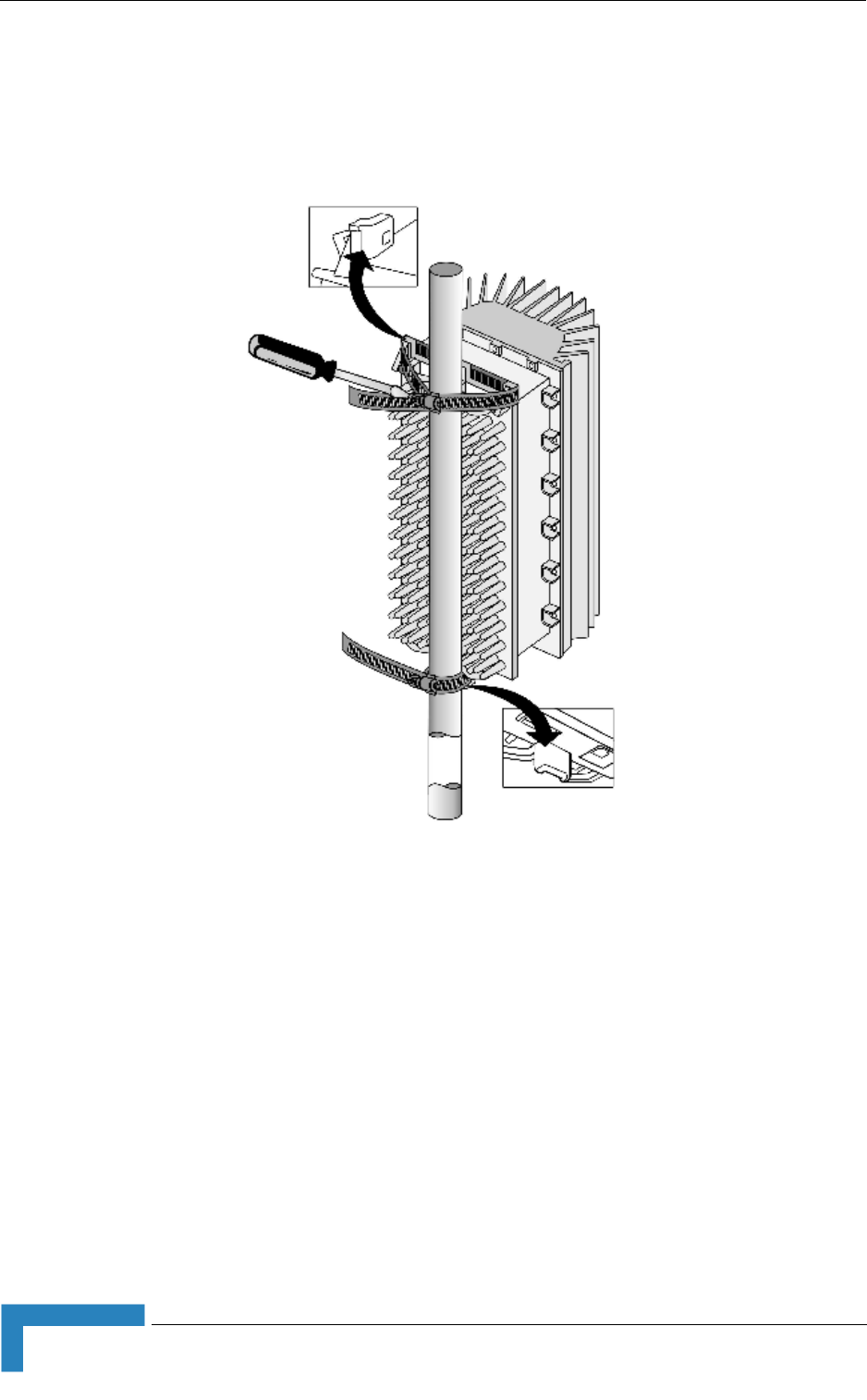
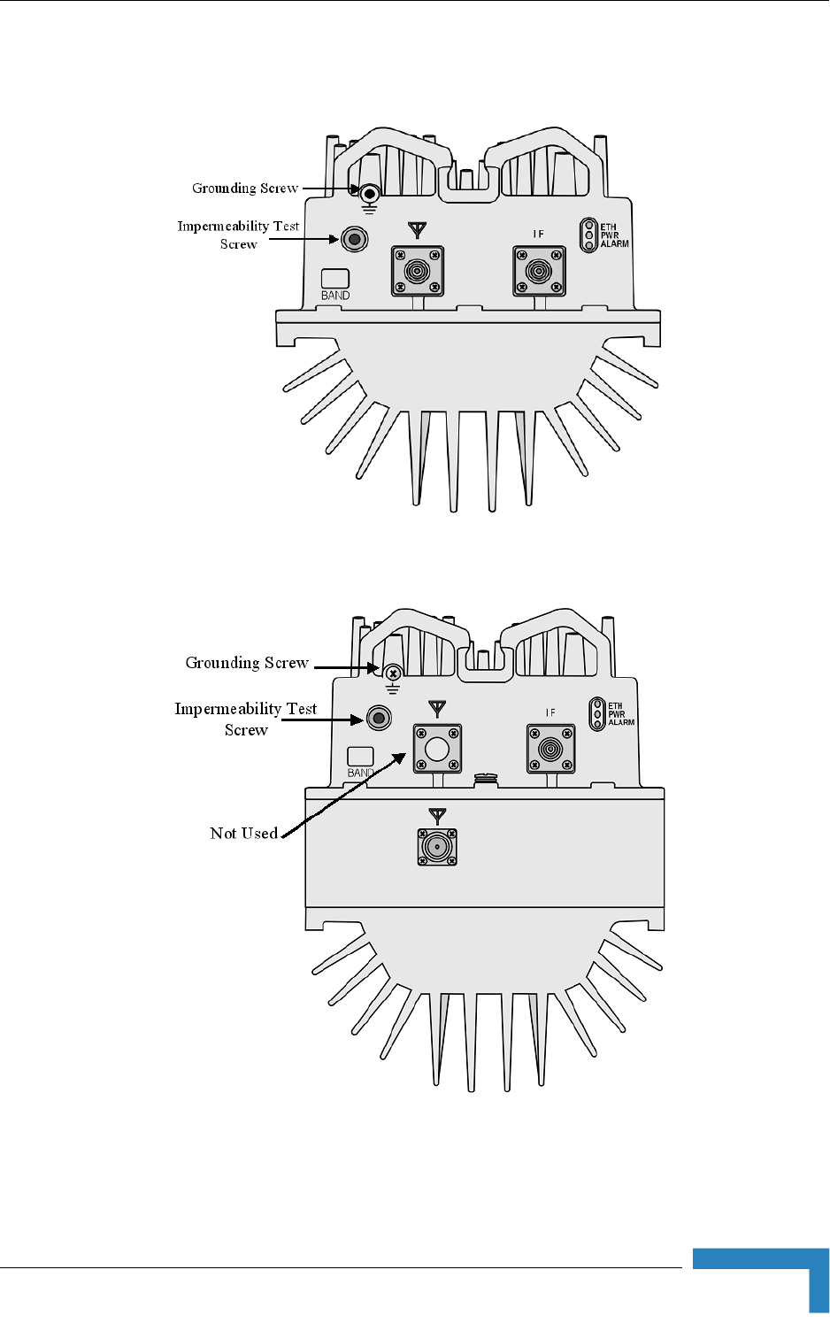
Installing the AU-ODU
BreezeMAX Modular Base Station System Manual 37
2.1.5 AU-ODU
Figure 2-3: Bottom Panel of the AU-ODU (except 2.3 GHz WCS)
Figure 2-4: Bottom Panel of the AU-ODU - 2.3 GHz WCS
38 Installation
Chapter 2 - Installation Guidelines
2.1.6 Connecting the Cables
2.1.6.1 Connecting the Grounding Cable
The Grounding screw (marked ) is located on the bottom panel of the outdoor
unit.
1Connect one end of a grounding cable to the grounding screw and tighten the
grounding screw firmly.
2Connect the other end of the grounding cable to a good ground (earth)
connection.
CAUTION
Do not open the impermeability test screw - you may impair the sealing of the unit against moisture
and humidity.
Table 2-3: AU-ODU LEDs
Name Description Functionality
PWR Power indication Off - Power failure
Green - Power to ODU is OK, internal 3.3
VDC power supply is OK.
ALARM IDU-ODU communication and
synthesizer status indication
Off - IDU-ODU communication is OK,
synthesizer is locked.
Red - IDU-ODU communication failure or
synthesizer is not locked
ETH Not Used
Table 2-4: AU-ODU Connectors
Name Connector Functionality
IF TNC jack Connection to the AU-IDU/ODU Power Feeder
ANT N-Type jack, 50 Ohm Connection to an external antenna
(GND) Grounding screw Connection to ground (earth)
To connect the grounding cable:

Installing the AU-ODU
BreezeMAX Modular Base Station System Manual 39
2.1.6.2 Connecting the Antenna Cable
1Connect one end of the coaxial RF cable to the RF connector (marked )
located on the bottom panel of the unit.
2Connect the other end of the RF cable to the antenna.
3The RF connectors should be properly sealed to protect against rain and
moisture.
2.1.6.3 Connecting the IF Cable
1Connect one end of the coaxial IF cable to the IF connector on the bottom
panel of the unit.
2Verify that the length of the IF cable is sufficient to reach the AU-IDU/Power
Feeder. See IF cable length limitation in Section 2.1.3.
3The IF cable connector should be properly sealed to protect against rain and
moisture.
4Route the cable to the location selected for the indoor equipment.
To connect the RF cable:
To connect the IF cable:

40 Installation
Chapter 2 - Installation Guidelines
2.2 Installing the Base Station Equipment
2.2.1 BST Installation Requirements
2.2.1.1 Packing List
Base Station Chassis:
BMAX-BST-SH Base Station Chassis
BMAX-BST-AVU Air Ventilation Unit (installed)
Cables Tray kit
BMAX-BST-PIU (1 or 2 per chassis) Power Interface Unit(s), or
BMAX-4M-BST-PIU (1 or 2 per chassis) High-Power Interface Unit(s). A
suitable DC power cable is supplied with each PIU.
BMAX-BST-PSU (up to 4 per chassis) Power Supply Unit(s)
BMAX-BST-TDD-NPU Network Processing Unit and Monitor cable
BMAX-BST-AU-IDU-4CH (up to 6 per chassis) Access Unit Indoor Unit(s)
2.2.1.2 Additional Installation Requirements
The following items are also required to install the BST:
Ethernet cable (straight) for connecting the NPU to a Hub/Switch.
A grounding cable with appropriate terminations for connecting the chassis to
the rack or another ground (earth) connection.
For installation in a 21" ETSI rack: Two 21" ETSI rack adapters
A portable PC for configuring parameters using the Monitor cable (supplied
with the NPU)
NOTE
The maximum length of the Ethernet cable is 100m when operating at 100 Mbps and 70m when
operating at 1 Gbps.
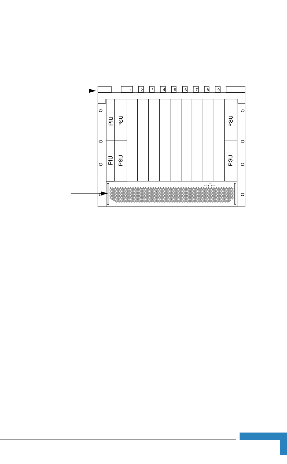
Installing the Base Station Equipment
BreezeMAX Modular Base Station System Manual 41
Other installation tools and materials
2.2.2 BMAX-BST-SH Chassis Slot Assignments
The Base Station chassis comprises 6 3U high slots and 9 6U high slots, as shown
in Figure 2-5.
The Cable Tray (the installation kit is supplied with the chassis) should be
installed on the top of the chassis front to enable convenient routing of cables
connecting to power source(s), outdoor unit(s) and other equipment.
To enable power source and/or Power Interface Unit 1+1 redundancy, two PIU
modules can be installed in the designated slots. If a single PIU module is used, it
can be inserted into either one of the two available slots.
The number of installed PSU modules depends on the specific configuration
(number of AUs) and NPU redundancy scheme (refer to Table 2-7). If less than 4
PSU modules are used, they can be installed in any of the designated slots.
The NPU should be installed in slot number 5 (slot numbers are marked on the
Cable Guide). Slot 6 is reserved for a future redundant NPU.
Slots 1-4 and 7-9 can hold up to six AU-IDU modules.
Unused slots should remain covered until required.
Figure 2-5: BMAX-BST-SH Chassis Slot Assignments
Air
Ventillation
Unit
Cable Tray

42 Installation
Chapter 2 - Installation Guidelines
2.2.3 Power Requirements
Use the following table to calculate worst-case power source requirements for the
Base Station equipment:
Table 2-5: Power Requirements, Base Station Equipment
Unit Details
Power Source -40.5 to -60 VDC
Regular PIU Power Consumption: 16W maximum (active PIU)
Maximum Supplied Current: 35 A
High-Power PIU Power Consumption: 35W maximum (active PIU)
Maximum Supplied Current: 58 A
PSU 200W max output power
Efficiency: 80% minimum
NPU 65W maximum, excluding power required for GPS Adapter
(1.2W maximum) and Outdoor GPS Receiver (6W
maximum)
AU-IDU-4CH 46W maximum
AU-ODU-HP-2.x GHz
(from PIU or Power Feeder)
Tx (DL): 89W maximum
Rx (UL): 15W maximum
AU-ODU-HP-3.x GHz
(from PIU or Power Feeder)
Tx (DL): 90W maximum
Rx (UL): 20W maximum
AVU 24W maximum
Power Feeder 2W per Channel
GPS Adapter (from NPU) 1.2W maximum
Indoor GPS Receiver
(directly form power source)
20W maximum
Outdoor GPS Receiver
(from NPU via GPS Adapter)
6W maximum
NOTE
The PSU(s) do not supply power to the AU-ODUs. Up to 8 AU-ODUs can be powered directly from
the power source via the regular PIU and the back plane. The new High-Power PIU can support up
to 20 AU-ODUs. Additional AU-ODUs are powered from ODU Power Feeders.

Installing the Base Station Equipment
BreezeMAX Modular Base Station System Manual 43
Example:
A full 2.x GHz Base Station operating with DL-UL ratio of 60-40, with regular
PIU(s), 6 AU-IDUs, 24 ODUs (8 ODUs are powered via the AU-IDUs, 16 ODUs are
powered by 4 Power Feeders), a GPS Adapter and an Outdoor GPS Receiver.
Power Consumption of the Base Station, including GPS Adapter and Outdoor GPS
Receiver, excluding the ODUs: 16(PIU) + [65(NPU) + 1.2(GPS Adapter) +6(Outdoor
GPS Receiver) +24(AVU) +6*46(IDU)] / 0.8(PSU Efficiency)=481W.
Excluding the PIU(s), the total power that should be supplied by PSUs is 465W.
Since each PSU can support a maximum of 200W, we need at least 3 PSUs. A
fourth PSU will support a 3+1 redundancy.
When calculating the power requirements associated with the ODUs, we should
distinguish between the peak power consumption (maximum current) and the
average power consumption (taking into account Tx/Rx ratio) that affect the
requirements from a backup power source.
For a 2.x GHz system, the peak power consumption of the 24 ODUs, including the
power required for Power Feeders (20 channels), is 24*89 + 16*2 = 2168W. Thus,
the total peak power of the system under worst conditions is 481 + 2168 = 2649W.
The average power consumption of the 24 ODUs, assuming DL-UL (Tx/Rx) ratio of
60-40, is 24*(89*0.60 + 15*0.40) + 16*2 = 1459W. Thus, the average power
consumption of the system under worst case conditions is 481 + 1459 = 1940W.
2.2.4 HOT SWAP Support
The NPU, AU-IDU and PIU modules includes a blue HOT SWAP LED and a
micro-switch in the injector/ejector handle to support hot-swap control. After
releasing the ejector's button, the HOT SWAP LED should turn on, indicating that
power to/from the back-panel is disconnected and the module can be removed
safely. For more details refer to Section 2.2.9.
2.2.5 Power Interface Unit (PIU)
The single Euro PIU module is the interface between the Base Station site's DC
power source and the Base Station Chassis Power Supply Units and external
ODUs, which receive power via the IDUs.
The PIU filters and stabilizes the Base Station input power and protects the
system from power problems such as over voltage, surge pulses, reverse polarity
connection and short circuits. It also filters high frequency interference (radiated
emissions) and low frequency interference (conducted emissions) to the external
power source. Each Base Station chassis contains two slots for an optional 1+1
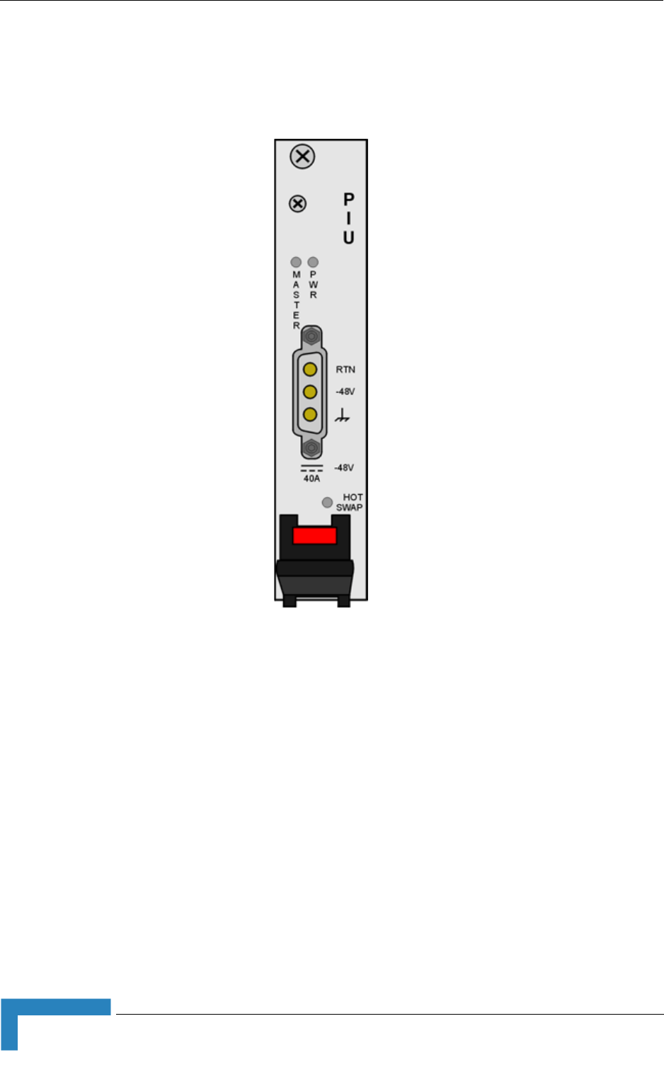
44 Installation
Chapter 2 - Installation Guidelines
PIU redundancy. One PIU is sufficient to support a fully populated chassis. Two
PIU modules provide redundant power feeding (two input sources) while avoiding
current flow between the two input sources.
Figure 2-6: Regular (35A) PIU Module Front Panel
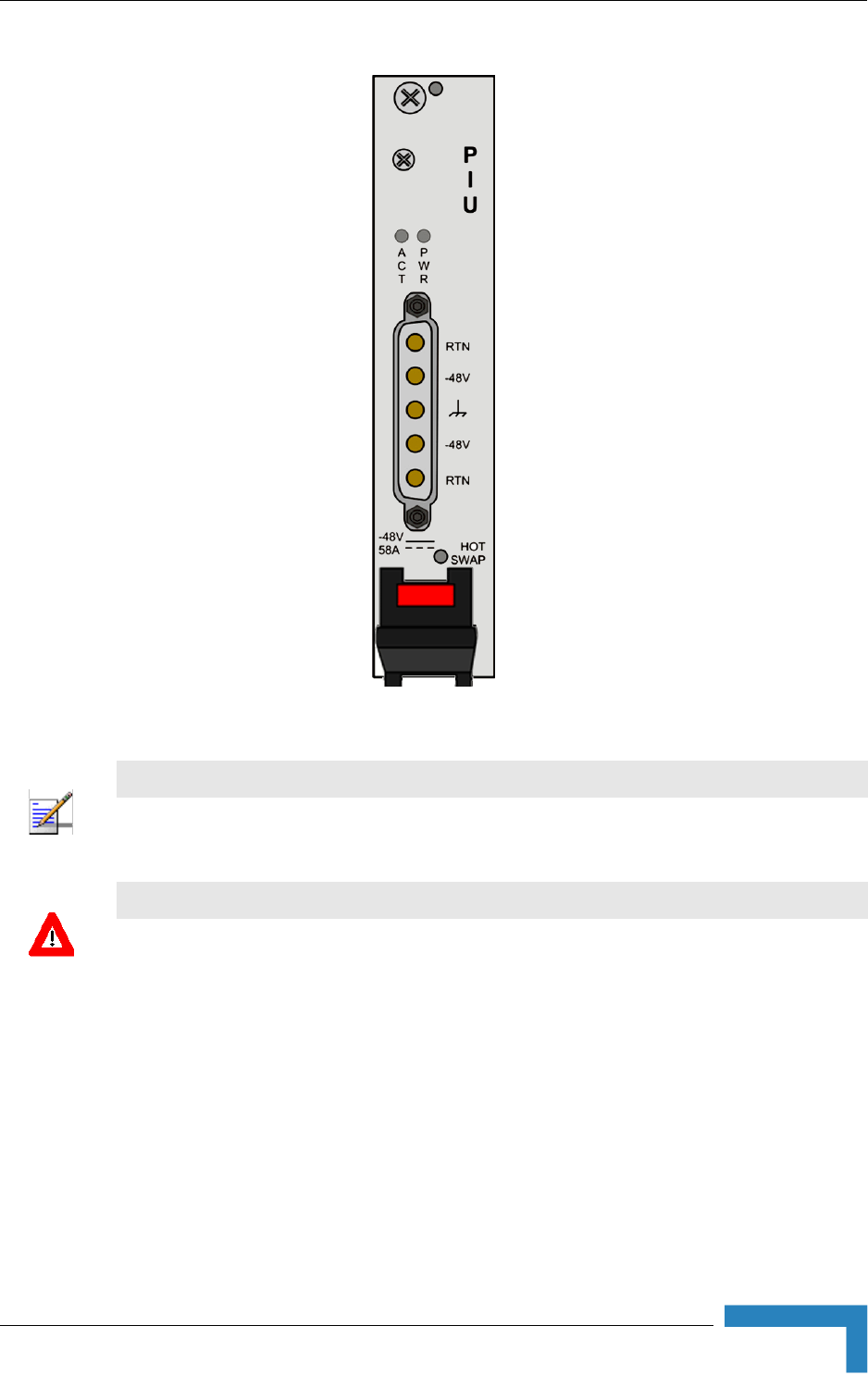
Installing the Base Station Equipment
BreezeMAX Modular Base Station System Manual 45
Figure 2-7: High-Power (58A) PIU Module Front Panel
NOTE
The HOT SWAP blue LED does not exist in first generation PIUs.
CAUTION
When replacing a PIU, disconnect power from the PIU module before inserting/ejecting it to/from
the chassis. If the PIU is with HOT SWAP LED, click on the handles and wait for the HOT SWAP
LED to turn on before disconnecting the power. After power is disconnected,disconnect the power
cable to avoid irreversible damage due to potential excessively high transient current. Connect
power to the PIU only after it is fully inserted into the chassis.
46 Installation
Chapter 2 - Installation Guidelines
2.2.5.1 Preparing a Power Cable for the regular (35A) PIU
A 2.5m DC power cable is supplied with each chassis. Additional DC cables can
be ordered from Alvarion. If necessary, use the following instruction to prepare a
DC cable.
1Use a cable capable of supporting a current of at least 40A. Use a cable with 2
x 8AWG (or thicker) wires for the power plus an additional 8AWG to 20AWG
ground wire.
2The matching power connector to be used is Amphenol D-type power P/N
177TWA/3W3/SP3Y with high power socket contacts P/N 17DM53744-1.
3Connect the cable to the power connector as follows:
Pin 1 (RTN): Red (8 AWG min wire)
Pin 2 (-48V): Black (8 AWG min wire)
Pin 3 ( ): Ground (shield) (8AWG-20AWG wire)
Table 2-6: PIU LEDs
PWR and
MASTER/ACT LEDs PIU Status
PWR MASTER/
ACT
Off Off Chassis is not connected to power
Red Off Power input is out of range or PIU card is damaged. Chassis is powered by the
redundant PIU
Red Green Power input is out of range or PIU card is damaged. Chassis is powered by the PIU
Green Off Power to PIU is OK. PIU is in redundant mode and the chassis is powered from the
other PIU
Green Green Power to PIU is OK. The chassis is powered from the PIU.
HOT SWAP LED Off: Power from the module to the chassis is not disconnected, the PIU is not ready for
removal
Blue: Power from the module to the chassis can be disconnected and the PIU can be
safely removed
For instructions on using the HOT SWAP handles refer to Section 2.2.9.
To prepare the power cable:
Installing the Base Station Equipment
BreezeMAX Modular Base Station System Manual 47
4Attach suitable terminal rings to the side that connects to the power source.
2.2.5.2 Preparing a Power Cable for the High-Power (58A) PIU
A 2.5m DC power cable is supplied with each chassis. Additional DC cables can
be ordered from Alvarion. If necessary, use the following instruction to prepare a
DC cable.
1For a cable length up to 2.5m use a cable with 4 x 10AWG (or thicker) wires for
the power plus and an additional 10AWG (or tghicker) ground wire. For a
longer cable (up to 10m), use a cable with 4 x 8AWG (or thicker) wires for the
power plus and an additional 10AWG (or tghicker) ground wire.
2The matching power connector to be used is D-SUB 5W5S Female with power
pins 40A.
3Connect the cable to the power connector as follows:
Pin 1 (RTN): Red (10/8 AWG min wire)
Pin 2 (-48V): Black (10/8 AWG min wire)
Pin 3 ( ): Ground (shield), Green/Yellow (10AWG min wire)
Pin 4 (-48V): Black (10/8 AWG min wire)
Pin 1 (RTN): Red (10/8 AWG min wire)
4Attach suitable terminal rings to the side that connects to the power source.
2.2.6 Power Supply Unit (PSU)
The single Euro PSU module is a 48 VDC power supply unit. Each Base Station
chassis can contain up to four PSU modules providing N+1 redundancy
configurations.
The following table displays the number of PSU modules (excluding redundant
units) required for various Base Station configurations:
To prepare the power cable:
CAUTION
It is strongly recommended to always use the power cables available from Alvarion.
Due to the high current that should be supported by the cable, good workmanship in preparing it is
essential.
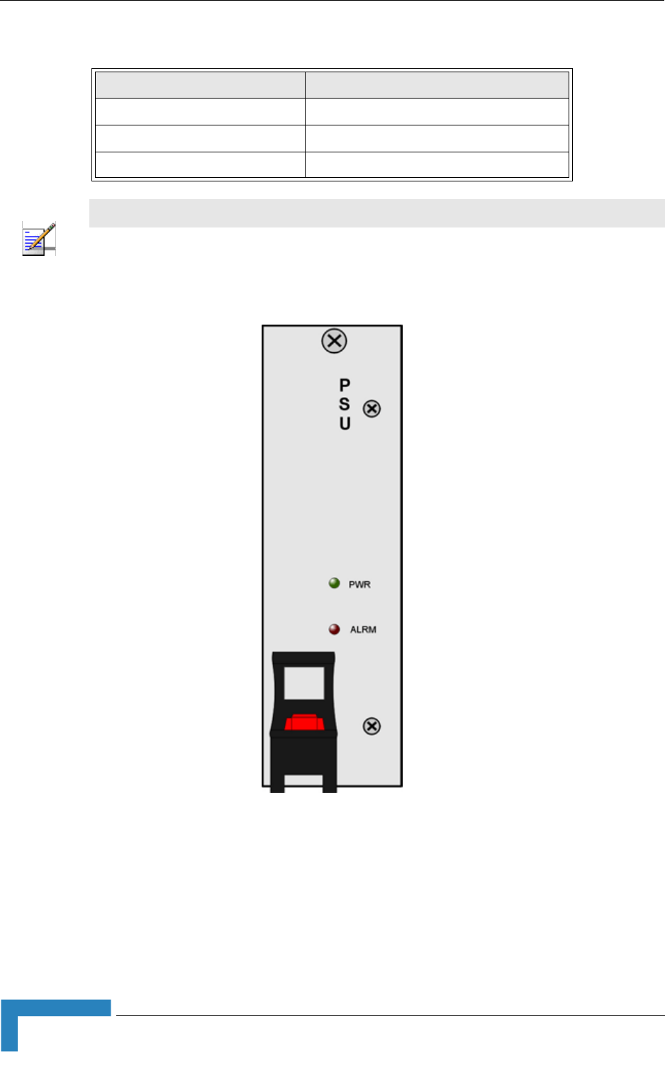
48 Installation
Chapter 2 - Installation Guidelines
Table 2-7: PSU Requirements, Configurations with one NPU (excluding PSU redundancy)
Number of AU-IDUs Minimum Required Number of PSUs
1 - 2 1
3 - 4 2
5 -6 3
NOTE
The PSU(s) do not supply power to the AU-ODUs. Up to 6 AU-ODUs can be powered directly from
the power source via the PIU and the back plane. Additional AU-ODUs are powered from ODU
Power Feeders.
Figure 2-8: PSU Module Front Panel

Installing the Base Station Equipment
BreezeMAX Modular Base Station System Manual 49
Table 2-8: PSU LEDs
LED Status Description
PWR ALRM
Off Off No power or fatal damage
Off Red Power input is out of range or PSU is damaged or PSU is inhibited by NPU
Green Off Power is OK and PSU operates properly
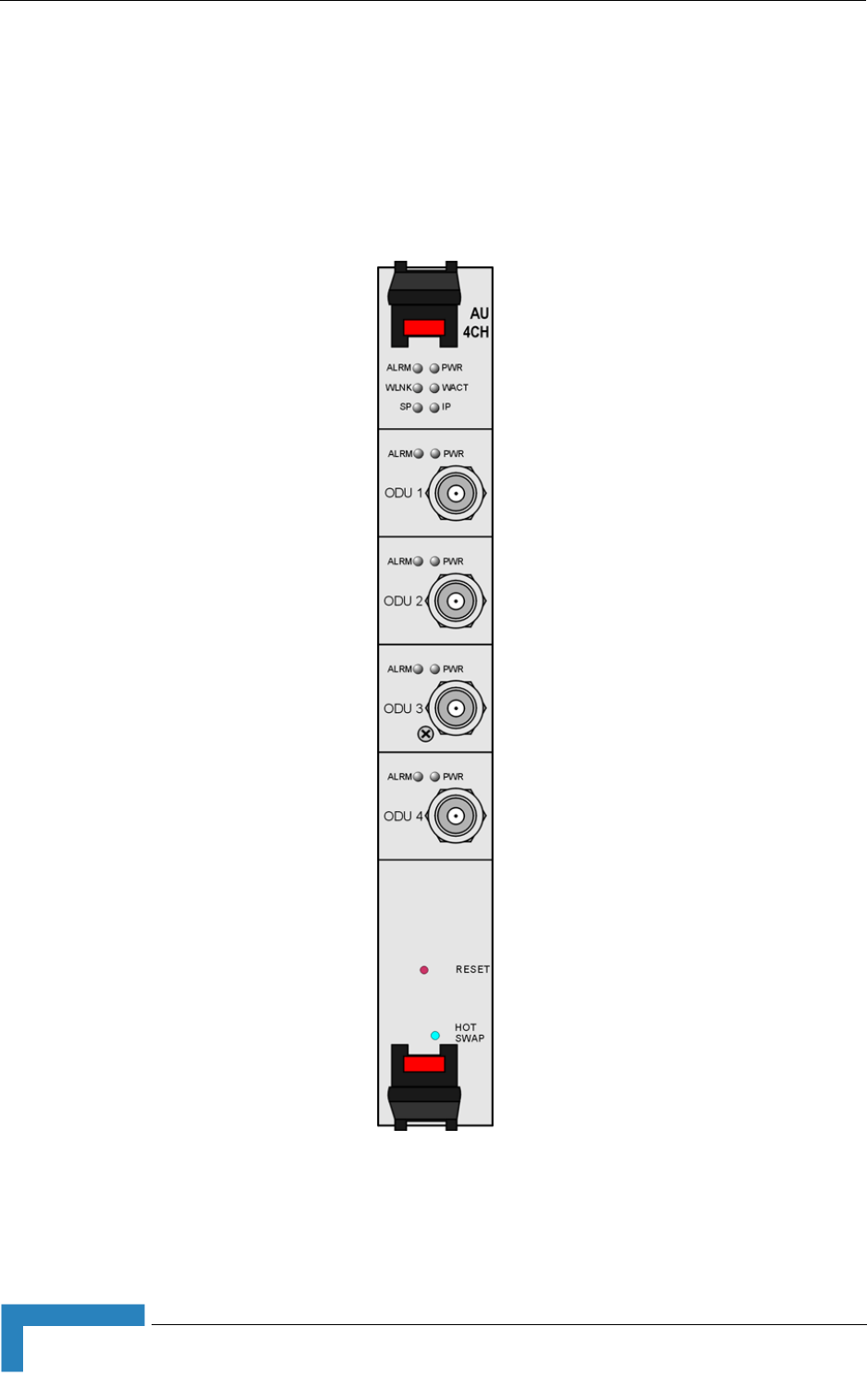
50 Installation
Chapter 2 - Installation Guidelines
2.2.7 Access Unit Indoor Module (AU-IDU)
The double Euro Access Unit IDU module contains the wireless MAC and modem
and is responsible for the wireless network connection establishment and for
bandwidth management. Each AU-IDU includes four PHY channels that can
connect to AU-ODUs.
Figure 2-9: AU-IDU Module Front Panel

Installing the Base Station Equipment
BreezeMAX Modular Base Station System Manual 51
Table 2-9: AU-IDU LEDs
Name Description Functionality
PWR Power indication Off - AU-IDU is not powered
Red - AU-IDU power supply failed (low power)
Green - AU-IDU power is OK
ALRM Alarm indication Off - AU-IDU is OK
Red - AU-IDU failure
WLINK Wireless link status indication Off - No SU is associated
Green - At least one SU is associated
WACT IDU transmission indication Off - No IDU transmission
Green - IDU transmission OK
SP Spare Not Used
IP IP activity indication Off - No downlink (AU to SU) IP activity
Green (blinking) - Downlink (AU to SU) IP activity
ODU1 - ODU4 PWR IDU to ODU Power Indication Off - No IDU to ODU power output
Red - IDU to ODU power output failed
Green - IDU to ODU power output OK
ODU1 -ODU4 ALRM IDU to ODU communication
status
Off - IDU-ODU communication OK
Red - IDU-ODU communication failure
HOT SWAP IDU readiness for hot swap
removal
Off: Power to the module is not disconnected,
the AU-IDU is not ready for removal
Blue: Power to the module can be disconnected
and the AU-IDU can be safely removed
For instructions on using the HOT SWAP handles
refer to Section 2.2.9.
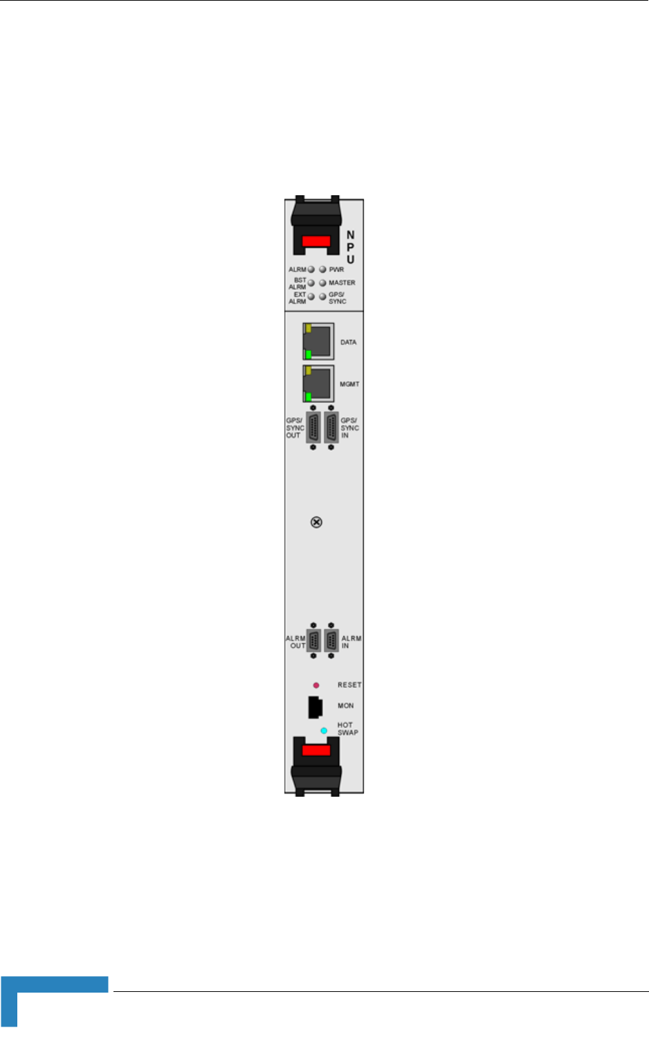
52 Installation
Chapter 2 - Installation Guidelines
2.2.8 Network Processing Unit (NPU)
The NPU module serves as the central processing unit that manages the base
station's components and the SUs served by it. It also aggregates the traffic from
the AU modules and transfers it to the IP backbone through a dedicated
Gigabit/Fast Ethernet interface.
Figure 2-10: NPU Module Front Panel

Installing the Base Station Equipment
BreezeMAX Modular Base Station System Manual 53
Table 2-10: NPU Connectors
Name Connector Functionality
DATA 100/1000Base-T (RJ-45)
with 2 embedded LEDs.
Connection to the backbone. Cable connection to a
hub/switch/router: Straight
MGMT 10/100Base-T (RJ-45)
with 2 embedded LEDs.
Connection to OOB management.
Cable connection to a PC: Crossed
Cable connection to a hub/switch/router: Straight
GPS/SYNC IN 15-pin micro D-Type jack Connection to a GPS Adapter (or, in the future, to another
NPU) that supplies synchronization signals.
GPS/SYNC OUT 15-pin micro D-Type jack Not used currently. Supply of synchronization signals to
another unit
ALRM-IN 9-pin micro D-Type jack Not used currently. Connections to external alarm indicators
(3 alarm inputs, NC or NO)
ALRM-OUT 9-pin micro D-Type jack Not used currently. Connections for activation of external
devices (4 dry contact pairs)
MON 3-pin low profile jack Access for debugging and configuration using the Monitor
program
Table 2-11: NPU LEDs
Name Description Functionality
PWR Power indication Off - NPU is not powered
Red - NPU power failure
Green - NPU power is OK
ALRM NPU Alarm indication Off - NPU is OK
Red - NPU failure
BST ALRM Base Station chassis alarm
indication
Off - All Base Station modules are OK
Red - Failure in one (or more) Base Station modules
EXT ALRM External alarm indication Off - No alarms
Red - Alarm received via the ALRM IN connector (not
applicable in current release)
MASTER Master/Slave operation indication Off - Secondary NPU (backup). Not supported in
current release.
Green - Primary NPU

54 Installation
Chapter 2 - Installation Guidelines
2.2.9 Using the Hot Swap Injector/Ejector Handles
The Base Station modules include special handles for high-force
insertion/extraction of modules. Each of the 6U high modules (NPU, AU-IDU)
includes two such handles, whereas each of the 3U high-modules (PIU, PSU)
includes a single handle at the bottom of the front panel.
The bottom injector/ejector handle of the NPU and AU-IDU modules includes a
micro-switch to support hot-swap control. Second generation PIU modules also
support hot-swap, as indicated by the HOT SWAP blue LED.
2.2.9.1 Inserting Modules
1Firmly push in the module into its intended slot (slot 5 for the NPU, slot 1-4,
7-9 for AU-IDU).
2Press the handles up (the upper handle if available)/down (the lower handle)
simultaneously until you hear the locking click and the red buttons are
released. The blue HOT SWAP LED will briefly turn on (only in AU and NPU),
indicating that the module is being powered up.
3Secure the module in place by closing the screws at the top and bottom of the
front panel.
GPS/SYNC GPS/IF clock synchronization
functionality indication
Off - GPS/IF clock synchronization is disabled
Green - GPS/IF clock is synchronization enabled
HOT SWAP NPU readiness for hot-swap
removal
Off: Power to the module is not disconnected, the NPU
is not ready for removal
Blue: Power to the module can be disconnected and
the NPU can be safely removed
For instructions on using the HOT SWAP handles refer to
Section 2.2.9.
To insert a module with hot-swap support (NPU, AU-IDU, PIU):
CAUTION
In a PIU with HOT SWAP LED, connect power to the PIU only after it is fully inserted into the
chassis.
Table 2-11: NPU LEDs
Name Description Functionality
Installing the Base Station Equipment
BreezeMAX Modular Base Station System Manual 55
1Firmly push in the module into its intended slot.
2Press the handle down until you hear the locking click and the red button is
released.
3Secure the module in place by closing the screw at the top of the front panel.
2.2.9.2 Ejecting Modules
1Release the screws at the top and the bottom of the front panel.
2Press the handles' red button until the handles are unlocked.
3Wait until the blue HOT SWAP LED turns on, indicationg that the module has
been disconnected and can be removed.
4Press the handles down (the upper handle)/up (the lower handle) until the
module is unlocked, firmly hold the handles and take the module out of the
chassis.
NOTE
If a module is fully inserted without properly locking the handles, it will become operational.
However, in this state the hot-swap mechanism is not supported. A warning message (trap) will be
sent.
To insert a PSU or a PIU without HOT SWAP support:
CAUTION
In a PIU without HOT SWAP LED, disconnect power from the PIU module before inserting it to the
chassis.
To eject a module with hot-swap support (NPU, AU-IDU, new PIU):
CAUTION
In a PIU with HOT SWAP LED, disconnect power from the PIU module only after it is taken out from
the chassis (or after the HOT SWAP LED is turned on).
To eject a PSU or a PIU without HOT SWAP support:

56 Installation
Chapter 2 - Installation Guidelines
1Release the screw at the top of the front panel.
2Press the handle's red button until the handle is unlocked.
3Press the handle up until the module is unlocked, firmly hold the handle and
take the module out of the chassis.
2.2.10 Installing the Base Station Chassis and
Modules
The indoor equipment should be installed as close as possible to the location
where the IF cable(s) enters the building. The location of the indoor equipment
should take into account its connection to the power source(s) and to the base
station networking equipment.
1 Attach the Cable Guide to the top panel of the chassis using the screws and
washers supplied with the Cable Guide.
2Install the chassis in a 19" cabinet. For installation in a 21" cabinet, attach
suitable ETSI rack adapters to the chassis. To provide a sufficient space for
the Cable Guide and to allow air flow for preventing over-heating, leave a free
space of at least 1U between the upper covers of the chassis and other units in
the cabinet.
3Connect one end of a grounding cable to the ground terminal located on the
rear panel of the chassis and firmly tighten the grounding screw. Connect the
opposite end of the grounding cable to a ground connection or to the cabinet, if
applicable.
4Carefully insert the modules into the relevant slots. Secure the modules in
their intended locations (refer to Section 2.2.9.1 for instructions on modules'
insertion).
5Place blank covers over all of the unused slots.
6Connect the DATA port of the NPU to the backbone data equipment (use a
straight Ethernet cable to connect to a hub/switch/router). The maximum
CAUTION
In a PIU without HOT SWAP LED, disconnect power from the PIU module before ejecting it from the
chassis. Before disconnecting the power cable from the PIU, the power source must be
disconnected to avoid irreversible damage due to a potential excessively high transient current.
To install the Base Station chassis and modules:

Installing the Base Station Equipment
BreezeMAX Modular Base Station System Manual 57
length of the Ethernet cable is 100m when operating at 100 Mbps and 70m
when operating at 1 Gbps.
7If the MGMT port will be used for remote management, connect it to the
appropriate data equipment (use a straight Ethernet cable to connect to a
hub/switch/router). The maximum length of the Ethernet cable is 100m.
8Connect the DC power cable to the power jack of the PIU module. If a
redundant PIU is installed, connect a DC power cable also to the second PIU
module. Connect the power cord(s) to the -48 VDC power source(s), as follows.
Connect the black wire to the 48 VDC contact of the power source.
Connect the red wire to the + (Return) contact.
Connect the ground wire to the ground.
9For AU-ODUs that connect directly to AU-IDUs: Connect the IF cable(s)
(already connected at the other end to the AU-ODU(s)) to the proper channels
(ODU 1 to ODU 4 connectors) of the applicable AU-IDU module(s). If only a
single AU-ODU per AU-IDU is used, connect the IF cable(s) to the appropriate
ODU-1 connector(s). To avoid transmissions at undesired frequencies, verify
that the frequency and bandwidth parameters are properly configured before
connecting the IF cables.
For AU-ODU that are powered by a Power Feeder: Refer to Section 2.3.3.
CAUTION
A maximum of eight AU-ODU-HP units can be powered directly from the Base Station (via the ODU
connectors of AU-IDUs) using regular (35A) PIU(s). High-Power (58A) PIU(s) can support up to 20
AU-ODU-HP units. Additional AU-ODU-HP units should be powered by ODU Power Feeder(s).
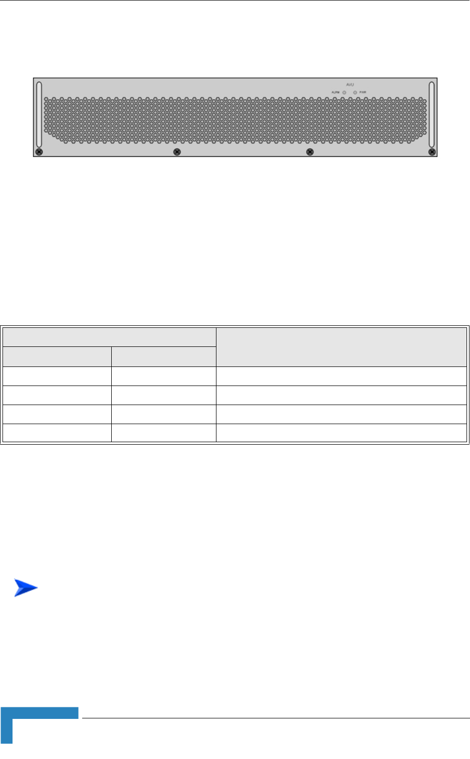
58 Installation
Chapter 2 - Installation Guidelines
2.2.11 Air Ventilation Unit (AVU)
The 2U high, 84 HP wide AVU includes a 1U high integral chamber for inlet
airflow and a 1U high fan tray with an internal alarm module. To support a high
availability Base Station, the fan tray includes 10 brush-less fans, where 9 fans
are sufficient for cooling a fully loaded chassis. To further support high
availability, the chassis can operate with the hot-swappable fan tray extracted
from it for a period of time sufficient for replacing it (up to 10 minutes).
If the red ALRM LED is on while the PWR LED is green, it indicates a failure of at
least one fan. Although the Base Station chassis may continue operating with one
failed fan, it is recommended to replace the AVU as soon as possible.
2.2.12 Replacing Base Station Components
2.2.12.1 Replacing an AVU
Release the 4 screws securing the AVU to the chassis.
Using the handle take out the faulty chassis.
Figure 2-11: AVU Drawer Front Panel
Table 2-12: AVU LEDs
LED Status Description
PWR ALRM
Off Off No 5V power input
Red Red 12V power failed
Green Red One or more fans have failed
Green Off AVU operates properly
To replace an AVU drawer:

Installing the Base Station Equipment
BreezeMAX Modular Base Station System Manual 59
Insert a new AVU drawer and close the screws. The replacement should be
completed in less than 10 minutes.
2.2.12.2 Replacing an NPU
To minimize downtime and facilitate fast and easy NPU replacement, it is
recommended to maintain an updated copy of the NPU configuration. Refer to
Section 4.6.2.6 for details on preparing and uploading a backup file of the NPU
configuration.
1Release the screws at the top and the bottom of the NPU's front panel.
2Press the handles' red button until the handles are unlocked.
3Wait until the blue HOT SWAP LED turns on, indicating that the module has
been disconnected and can be removed.
4Press the handles down (the upper handle)/up (the lower handle) until the
module is unlocked. Firmly hold the handles and take the module out of the
chassis.
5Disconnect all IF cables connecting the AU-IDUs to the AU-ODUs. This is
necessary as the initial configuration of the new NPU is most probably
inappropriate.
6Firmly push the new NPU module into its intended slot (slot 5).
7Press the handles up (the upper handle)/down (the lower handle)
simultaneously until you hear the locking click and the red buttons are
released. The blue HOT SWAP LED will briefly turn on, indicating that the
module is being powered up.
8Secure the module in place by closing the screws at the top and bottom of the
front panel.
9Download the backup file using a DOS based TFTP. Use the command: tftp i
<NPU port IP address> put <file name>. The default IP address of the MGMT
port is 10.0.0.1.
10 Use the monitor program to configure the IP parameters (IP address, Subnet
Mask, Default Gateway Address) of the MGMT port. These parameters are not
affected by the loaded file.
11 Reset the system.
12 Reconnect the IF cables.

60 Installation
Chapter 2 - Installation Guidelines
2.2.12.3 Replacing an AU-IDU
1Disconnect all IF cables connecting the AU-IDUs to AU-ODUs.
1Release the screws at the top and the bottom of the AU-IDU's front panel.
2Press the handles' red button until the handles are unlocked.
3Wait until the blue HOT SWAP LED turns on, indicating that the module has
been disconnected and can be removed.
4Press the handles down (the upper handle)/up (the lower handle) until the
module is unlocked. Firmly hold the handles and take the module out of the
chassis.
5Firmly push the new AU module into its intended slot.
6Press the handles up (the upper handle)/down (the lower handle)
simultaneously until you hear the locking click and the red buttons are
released. The blue HOT SWAP LED will briefly turn on, indicating that the
module is being powered up.
7Secure the module in place by closing the screws at the top and bottom of the
front panel.
8Reconnect the IF cables. Make sure that each ODU is connected to the
appropriate port on the AU.
9Wait until the AU reboot process is completed. This might take few minutes.
10 Reset the AU. (To perform the reset go to the main menu of the AU, select 2 -
Unit Control, than select 1 - Reset and confirm the reset. Alternatively, you can
press the reset button on the front panel of the AU).
11 Go to the main menu of the AU and verify that the all the parameters and the
SW Version are as expected.
12 Verify that the AU operates properly and that the SUs that should be served by
it are connected with the AU.
2.2.12.4 Replacing a PIU
1Release the screws at the top and the bottom of the PIU's front panel.
2Press the handle’s red button until the handles are unlocked.
3In units with a HOT SWAP LED, Wait until the blue HOT SWAP LED turns on,
indicating that the module has been disconnected and can be removed.
4Disconnect the power cable from the PIU

Installing the Base Station Equipment
BreezeMAX Modular Base Station System Manual 61
5Press the handle up until the module is unlocked. Firmly hold the handles and
take the module out of the chassis.
6Firmly push the new PIU module into its intended slot.
7Press the handle down until you hear the locking click and the red buttons are
released.
8Secure the module in place by closing the screws at the top and bottom of the
front panel.
9Connect power to the PIU only after it is fully inserted into the chassis.

62 Installation
Chapter 2 - Installation Guidelines
2.3 Installing the ODU Power Feeder
2.3.1 Installation Requirements
2.3.1.1 Packing List
A 19” panel (can hold up to three ODU Power Feeder modules).
ODU Power Feeder module, including a DC power cable, four 0.5 meter IF
cables and four screws.
2.3.1.2 Additional Installation Requirements
A grounding cable with appropriate terminations for connecting the unit's
ground terminal to the rack or to a ground connection.
For installation in a 21" ETSI rack: two 21" ETSI rack adapters
Other installation tools and materials
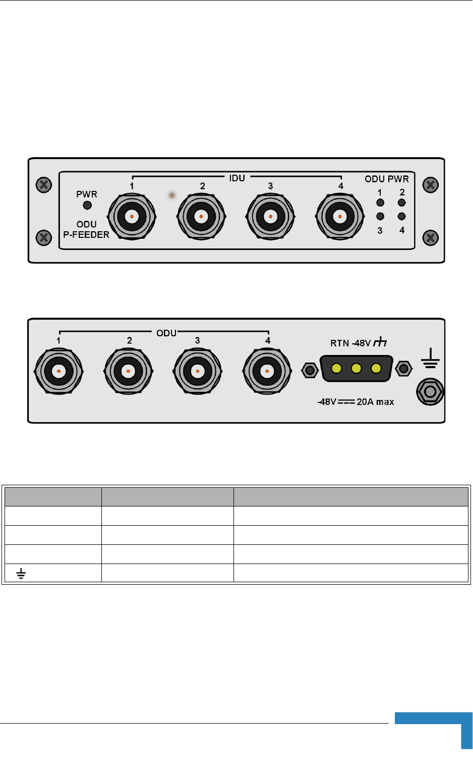
Installing the ODU Power Feeder
BreezeMAX Modular Base Station System Manual 63
2.3.2 The ODU Power Feeder
The ODU Power Feeder is used to provide power (-48 VDC) to AU-ODU-HP High
Power ODUs. It transfers transparently all signals between the AU-IDU and the
ODU, while injecting DC power received from an external source. Each ODU
Power Feeder unit can serve up to four High Power ODUs. Up to three ODU Power
Feeder units can be installed in a 1U high Power Feeder panel.
Figure 2-12: ODU Power Feeder Front Panel
Figure 2-13: ODU Power Feeder Rear Panel
Table 2-13: ODU Power Feeder Connectors
Name Connector Functionality
IDU 1 - 4 4 x TNC jacks Connection to ODU connectors of AU-IDUs
ODU 1 - 4 4 x TNC jacks Connections to IF connectors of AU-ODU-HP units
-48V 3-pin D-Type power jack Connection to DC power source
(GND) Grounding Screw Connection to ground (earth)

64 Installation
Chapter 2 - Installation Guidelines
2.3.2.1 Preparing a Power Cable
A 2.5m DC power cable is supplied with each ODU Power Feeder module.
Additional DC cables can be ordered from Alvarion. If necessary, use the following
instruction to prepare a DC cable.
1Use a cable capable of supporting a current of at least 10A. Use a cable with 2
x 10AWG (or thicker) wires for the power plus an additional 10AWG to 20AWG
ground wire.
2The matching power connector to be used is Amphenol D-type power P/N
177TWA/3W3/SP3Y with high power socket contacts P/N 17DM53744-1.
3Connect the cable to the power connector as follows:
Pin 1 (RTN): Red (10 AWG min wire)
Pin 2 (-48V): Black (10 AWG min wire)
Pin 3 ( ): Ground (shield) (10AWG-20AWG wire)
4Attach suitable terminal rings to the side that connects to the power source.
2.3.3 Installing the ODU Power Feeder
The ODU Power Feeder should be installed as close as possible to the location
where the IF cable(s) enters the building. The location of the ODU Power Feeder
should take into account its connection to the power source and to the Base
Station equipment.
Table 2-14: ODU Power Feeder LEDs
Name Description Functionality
PWR Input power indication Off - ODU Power Feeder is not powered
Green - ODU Power Feeder power is OK
ODU PWR 1 - 4 Output power indications Off - AU-ODU-HP is not connected
Red - Power output problem (short or overload)
Green - AU-ODU-HP is connected and powered
To prepare the power cable:

Installing the ODU Power Feeder
BreezeMAX Modular Base Station System Manual 65
1The panel is supplied with blank covers. Release the nuts on the rear side of
the panels to remove the blank cover(s) you want to replace with ODU Power
Feeder module(s). Attach the ODU Power Feeder module(s) to the panel using
the four screws supplied with each module.
2Place the panel with the ODU Power Feeder module(s) on a shelf/desk or
install it in a 19" cabinet, next to the Base Station equipment. For installation
in a 21" cabinet, attach suitable ETSI rack adapters to the chassis.
3Connect one end of a grounding cable to the grounding screw located on the
rear panel of each ODU Power Feeder module and firmly tighten the grounding
screw. Connect the opposite end of the grounding cable(s) to a ground (earth)
connection or to the cabinet, if applicable.
4Connect the IDU connector(s) to the appropriate ODU connector(s) of the
AU-IDU(s) using the short (0.5 meter) IF cables supplied with the module.
5Connect the power cord to the ODU Power Feeder’s DC socket, located on the
rear panel. Connect the other end of the power cord to the -48 VDC power
source.
6Connect the IF cable(s), that should already be connected at the other end to
the AU-ODU-HP(s), to the appropriate ODU connector(s). To avoid
transmissions at undesired frequencies, verify that the frequency and
bandwidth parameters are properly configured before connecting the IF cables.
To install the ODU Power Feeder:

66 Installation
Chapter 2 - Installation Guidelines
2.4 Installing the GPS Adapter
2.4.1 Installation Requirements
2.4.1.1 Packing List
A 19” panel (can hold also ODU Power Feeder modules).
GPS Adapter module, including a 2m NPU to GPS Adapter cable and four
screws.
2.4.1.2 Additional Installation Requirements
A grounding cable with appropriate terminations for connecting the unit's
ground terminal to the rack or to a ground connection.
For installation in a 21" ETSI rack: two 21" ETSI rack adapters
Other installation tools and materials
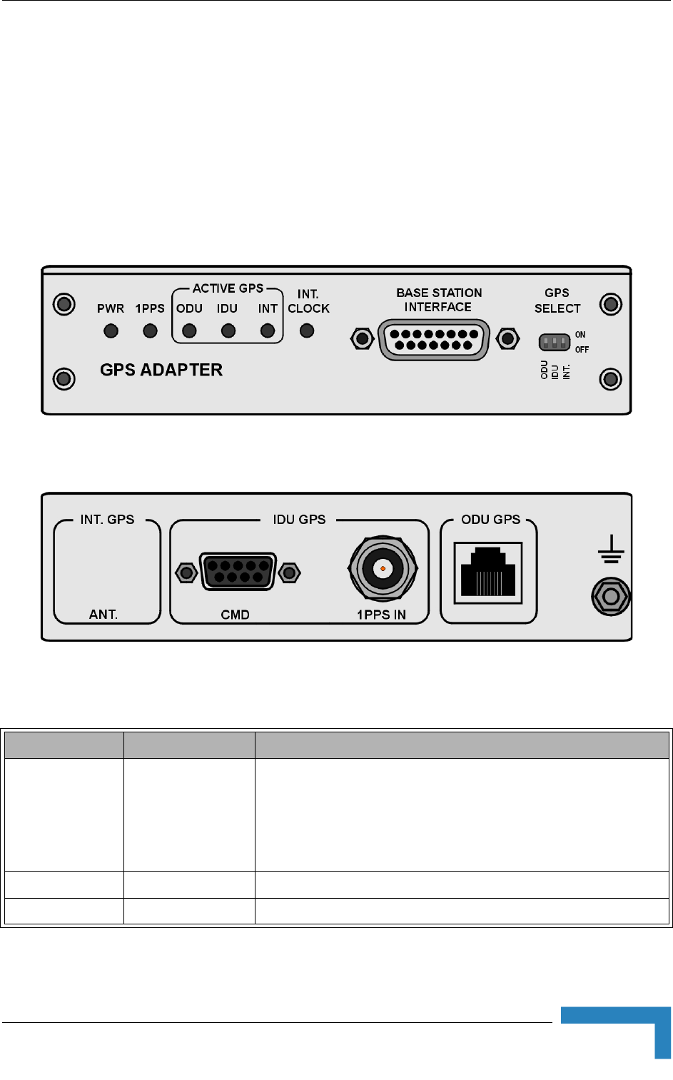
Installing the GPS Adapter
BreezeMAX Modular Base Station System Manual 67
2.4.2 The GPS Adapter
The GPS Adapter connects the different GPS units to the NPU, adapting the
different interfaces. Future versions may include an internal GPS module that will
allow an all-in-one low-cost solution. A future optional addition of OCXO in the
GPS Adapter box may provide an improved hold over solution when the GPS is not
synchronized. The GPS Adapter is powered by 12 VDC supplied by the NPU. The
GPS Adapter is installed in a 1U high panel (the same panel that is used for the
ODU Power Feeders).
Figure 2-14: GPS Adapter Front Panel
Figure 2-15: GPS Adapter Rear Panel
Table 2-15: GPS Adapter Connectors
Name Connector Functionality
BASE STATION
INTERFACE
15 pin D-Type jack 1PPS and 16MHz synchronization signals (LVDS interface) to the
NPU
Power (12 VDC) from the NPU
Serial control signals (RS-442 interface) from the NPU
CMD 9 pin D-Type jack Serial control signals (RS-232 interface) to the Indoor GPS Receiver.
1PPS IN BNC jack 1PPS signal (TTL levels) from Indoor GPS Receiver

68 Installation
Chapter 2 - Installation Guidelines
2.4.3 Installing the GPS Adapter
1The GPS Adapter is installed on the 1U high panel that can be used also for
installation of ODU Power Feeder modules. The panel is supplied with blank
ODU GPS RJ-45 jack 1PPS (RS-442 interface) from Outdoor GPS Receiver
Serial control signals (RS-422 interface) to Outdoor GPS Receiver
Power (12 VDC) to Outdoor GPS Receiver
(GND) Grounding Screw Connection to ground (earth)
Table 2-16: GPS Adapter LEDs
Name Description Functionality
PWR Input power indication Off - Power input failure
Green - 12 VDC power supply from NPU is OK
1PPS 1PPS signal indication Blinking Green - 1PPS signal from GPS Receiver
is detected
Red - 1PPS signal is not detected
Active GPS - ODU ODU GPS selection indication Green - indicates that the selected GPS Receiver:
is ODU (Outdoor)
Off - ODU GPS Receiver is not selected
Active GPS - IDU IDU GPS selection indication Green - indicates that the selected GPS Receiver:
is IDU (Indoor)
Off - IDU GPS Receiver is not selected
Active GPS - INT INT GPS selection indication Green - indicates that the selected GPS Receiver:
is INT (Internal). Internal is not supported in current
release.
Off - INT GPS Receiver is not selected
INT CLOCK Internal clock source indication Green - Internal 16MHz clock is ok (not supported
in current release)
Red - Internal clock is not available or clock failure
To install the GPS Adapter:
Table 2-15: GPS Adapter Connectors
Name Connector Functionality

Installing the GPS Adapter
BreezeMAX Modular Base Station System Manual 69
covers. Release the nuts on the rear side of the panel to remove the blank
cover you want to replace with the GPS Adapter. Attach the GPS Adapter
module to the panel using the four screws supplied with it.
2Place the panel with the GPS Adapter (and optionally ODU Power Feeders) on a
shelf/desk or install it in a 19" cabinet, next to the Base Station equipment.
The distance from the Base Station equipment should allow connection of the
2 meters NPU to GPS Adapter cable. For installation in a 21" cabinet, attach
suitable ETSI rack adapters to the panel.
3Connect one end of a grounding cable to the grounding screw located on the
rear panel of the GPS Adapter and firmly tighten the grounding screw. Connect
the opposite end of the grounding cable to a ground (earth) connection or to
the cabinet, if applicable.
4Connect the NPU-to-GPS Adapter cable to the BASE STATION INTERFACE
connector on the front panel of the GPS Adapter. Connect the other end of the
cable to the GPS/SYNC IN connector of the NPU.
5Select the GPS Receiver to be used using the GPS SELECT miniature DIP
switches:
To use Outdoor GPS Receiver, move the ODU (left-most) switch to the ON
(up) position. Make sure that the two other switches are in the OFF (down)
position.
To use Indoor GPS Receiver, move the IDU (middle) switch to the ON (up)
position. Make sure that the two other switches are in the OFF (down)
position.
The INT (Internal) GPS Receiver option is not available in current release.
6Connect the applicable cable(s) to the selected GPS Receiver.
NOTE
Refer to the documentation supplied with the GPS Receiver for instructions on how to install and
connect it.
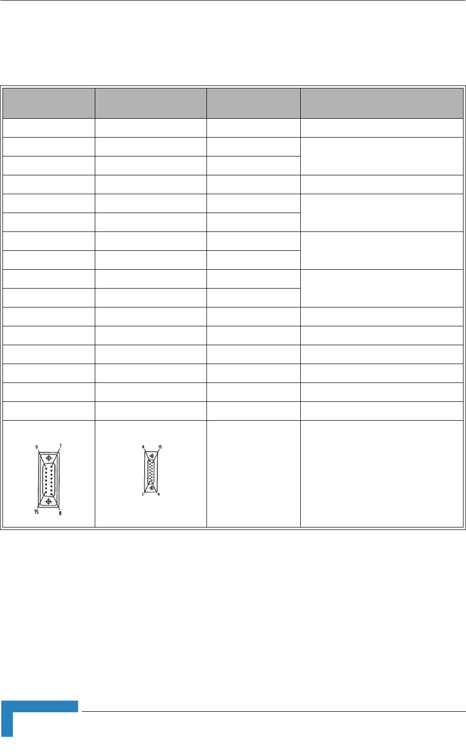
70 Installation
Chapter 2 - Installation Guidelines
2.4.4 NPU to GPS Adapter Cable
Table 2-17: NPU to GPS Adapter Cable Pin Out
DB 15-pin Male
(GPS Adapter) Micro 15-pin Female
(NPU) Name Description
1 1 IN_SENSE GPs Adapter Presence Indication
2 2 EXT_16M_IN- External 16MHz clock from GPS
Adapter, LVDS twisted pair (Not Used)
10 10 EXT_16M_IN+
3 3 NC Not Used
4 4 1PPS_IN+ 1PPS signal from GPS Adapter, LVDS
twisted pair,
11 11 1PPS_IN-
5 5 GPS_TX- Transmit communication channel from
GPS, RS422 twisted pair
13 13 GPS_TX+
6 6 GPS_RX- Receive communication channel to
GPS, RS422 twisted pair
14 14 GPS_RX+
7 7 NC Not Used
8 8 GND Ground
9 9 GND Ground
12 12 NC Not Used
15 15 +12V 12 VDC to GPS
Shell Shell Shield
Installing the GPS Adapter
BreezeMAX Modular Base Station System Manual 71
2.4.5 GPS Adapter to Outdoor GPS Receiver Cable
Table 2-18: GPS Adapter to Outdoor GPS Receiver Cable Pin Out
12-pin Bayonet
(GPS Receiver) RJ 45
(GPS Adapter) Name Wire Color Description
1 2 Power (12 VDC) Orange Twisted pair
9 1 Ground Orange/White
2 5 Receive- Blue RS422 twisted pair
3 6 Receive+ Blue/White
4 4 Transmit- Brown RS422 twisted pair
5 3 Transmit+ Brown/White
11 8 1PPS+ Green/White RS422 twisted pair
12 7 1PPS- Green
NC Case Shield

72 Installation
Chapter 2 - Installation Guidelines


74 Commissioning
Chapter 3 - Commissioning
3.1 Configuring Basic Parameters of Base
Station
3.1.1 NPU Parameters Required for Management
After completing the installation process, as described in the preceding chapter,
some basic NPU parameters must be configured using the Monitor application via
the MON port of the NPU. These parameters are necessary to enable remote
management using SNMP or Telnet.
If the NPU is in the default factory configuration, or if the IP parameters of either
the Data or Management port are known, you may configure the parameters using
Telnet. You may also use AlvariCRAFT, provided you know the IP parameters of
one port and the Authorized Managers list in the NPU is either empty (default) or
includes the IP address of the AlvariCRAFT station.
Refer to Chapter 4 for information on how to access the Monitor application either
via the MON port or via Telnet and how to use it.
Refer to the AlvariCRAFT User Manual for information on how to use it.
The basic parameters are listed in Table 3-1. Refer to Chapter 4 for detailed
information on the applicable parameters.
NOTE
The default Installer password is "installer".
Table 3-1: Basic NPU Parameters
Management Option Parameters
MGMT port Management Port IP address
Management Port Subnet Mask
Management Port Gateway
Management Port Destination Subnet
Management Port Destination Subnet Mask
Management Port Management Traffic Enable/Disable

Configuring Basic Parameters of Base Station
BreezeMAX Modular Base Station System Manual 75
The following are the guidelines for configuring the basic NPU parameters:
All parameters of both ports should be configured. Otherwise, default values
shall be used.
If OOB management via a router connected to the Management port is used,
the parameters should be configured to ensure different subnets for the Data
port, the Management port (local OOB management) and the Management Port
Destination. The Management Port Destination Subnet is the subnet behind a
router connected to the Management port.
Authorized Manager(s) must be configured properly to enable remote
management using AlvariSTAR (or another SNMP based application).
DATA port Data Port IP address
Data Port Subnet Mask
Data Port Gateway
Data Port Management VLAN ID
Data Port Management Traffic Enable/Disable
Data Port Speed
Authorized Managers
(per manager)
IP Address
Send Traps
Read Community
Write Community
NOTE
It is highly recommended to use the Management port for local management only. Typically the port
should be down (disconnected).
CAUTION
Do not configure the IP Address of the Management port to 0.0.0.0, as this will cause loss of
management connectivity via the Data port.
Table 3-1: Basic NPU Parameters
Management Option Parameters

76 Commissioning
Chapter 3 - Commissioning
After the basic NPU parameters have been configured, the Base Station can be
managed remotely using either Telnet or SNMP-based management.
To enable proper operation of the Base Station and all its components, the
following parameters must also be configured:
3.1.2 Base Station Configuration Parameters
Switching Mode
Operator ID
Cell ID
Duplex Mode (must be TDD)
DL-UL Ratio
External 1PPS Clock (must be enabled to support 1PPS from GPS)
External 16MHz Clock (in this release must be disabled)
Chain Number
GPS Protocol
Time Zone Offset From UTC
3.1.3 RADIUS Parameters
3.1.3.1 RADIUS General Parameters
Shared Secret
NOTE
If no Authorized Manager is defined in the device, it can be managed using SNMP by any station. If
at least one Authorized Manager is defined, the device can be managed only by a station whose
parameters match a defined Authorized Manager.
NOTE
The following list includes only parameters that are mandatory for proper operation of the Base
Station. Configuration of other parameters may be done either at the same time or later.

Configuring Basic Parameters of Base Station
BreezeMAX Modular Base Station System Manual 77
3.1.3.2 RADIUS Authentication
At least one Authentication server must be defined to enable RADIUS-based
provisioning of services (in IP CS Switching Mode only one server can be defined).
IP Address
UDP Port
Server Status (not applicable for units operating IP CS Switching Mode)
3.1.3.3 RADIUS Accounting
At least one Accounting server must be defined to enable RADIUS-based
accounting (in IP CS Switching Mode only one server can be defined).
IP Address
UDP Port
Server Status (not applicable for units operating IP CS Switching Mode)
3.1.4 Radio Cluster
Radio Cluster ID: Verify that all required Radio Cluster IDs are defined
3.1.5 ODU
Define the necessary ODUs. For each ODU, configure the following:
ODU ID
Associated Radio Cluster
Configured ODU Frequency Band
Configured Tx Power
Admin Status: Enable when completing the configuration process

78 Commissioning
Chapter 3 - Commissioning
3.1.6 AU
3.1.6.1 SW Files in NPU - Default SW File (Advanced Si)
Name
Action
The following must be configured for each AU:
3.1.6.2 Unit Control - SW Versions Control
3.1.6.2.1 SW File
Name
Action
3.1.6.2.2 SU SW File
Name
Action
3.1.6.3 MAC Parameters
Sector ID
Maximum Cell Radius (km)
3.1.6.4 Phy Parameters
Bandwidth
3.1.6.5 Multi Channel Parameters
Diversity Mode
The following parameters must be configured for each channel used if Diversity
Mode is No Diversity. Otherwise, only Channel 1 needs to be configured:
Associated ODU

Configuring Basic Parameters of Base Station
BreezeMAX Modular Base Station System Manual 79
Downlink (Tx) Frequency (MHz)
Admin Status: Enable when completing the configuration process
3.1.6.6 Multirate Parameters
Uplink Basic Rate
Minimum Number of Sub-Channels
Downlink Basic Rate
3.1.6.7 Voice Parameters
Maximum Number of Voice Calls (not applicable for IP CS Switching Mode)
AU Minimum allocation
3.1.7 SU
3.1.7.1 SW Files in NPU - Default SW File (Advanced Si)
Name
Action

80 Commissioning
Chapter 3 - Commissioning
3.2 Operation Verification
The following sections describe how to verify the correct functioning of the
Outdoor Units, Indoor Units, Ethernet connection and data connectivity.
3.2.1 AU-ODU LEDs
To verify the correct operation of the AU-ODU, examine the LED indicators located
on the bottom panel of the outdoor unit.
The following tables list the provided LEDs and their associated indications.
3.2.2 Base Station LEDs
To verify the correct operation of the Base Station equipment, examine the LED
indicators located on the front panels of the modules. The following tables list the
LEDs of the Base Station modules and their associated indications.
NOTE
Verifying the correct operation of the Outdoor Unit using the LEDs, as described below, is only
possible after the configuration of basic parameters has been completed.
Table 3-2: AU-ODU-LEDs
Name Description Functionality
PWR Power indication Off - Power failure
Green - Power to ODU is OK, internal 3.3
VDC power supply is OK.
ALARM IDU-ODU communication
and synthesizer status
indication
Off - IDU-ODU communication is OK,
synthesizer is locked.
Red - IDU-ODU communication failure or
synthesizer is not locked
ETH Not Used

Operation Verification
BreezeMAX Modular Base Station System Manual 81
Table 3-3: AU-IDU LEDs
Name Description Functionality
PWR Power indication Off - AU-IDU is not powered
Red - AU-IDU power supply failed (low power)
Green - AU-IDU power is OK
ALARM Alarm indication Off - AU-IDU is OK
Red - AU-IDU failure
WLINK Wireless link status indication Off - No SU is associated
Green - At least one SU is associated
WACT IDU transmission indication Off - No IDU transmission
Green - IDU transmission OK
SP Spare Not Used
IP IP activity indication Off - No downlink (AU to SU) IP activity
Green (blinking) - Downlink (AU to SU) IP activity
ODU1 - ODU4 PWR IDU to ODU Power Indication Off - No IDU to ODU power output
Red - IDU to ODU power output failed
Green - IDU to ODU power output OK
ODU1 - ODU4 ALRM IDU-ODU communication
status
Off - IDU-ODU communication OK
Red - IDU-ODU communication failure
HOT SWAP IDU readiness for hot swap
removal
Off: Power to the module is not disconnected, the
AU-IDU is not ready for removal
Blue: Power to the module can be disconnected
and the AU-IDU can be safely removed
For instructions on using the HOT SWAP handles refer
to Section 2.2.9.

82 Commissioning
Chapter 3 - Commissioning
Table 3-4: NPU LEDs
Name Description Functionality
PWR Power indication Off - NPU is not powered
Red - NPU power failure
Green - NPU power is ok
ALRM NPU Alarm indication Off - NPU is OK
Red - NPU failure
BST ALRM Base Station chassis alarm
indication
Off - All Base Station modules are OK
Red - Failure in one (or more) Base Station
modules
EXT ALRM External alarm indication Off - No alarm received via the AL IN connector
Red - Alarm received via the AL IN connector
MASTER Master/Slave
(primary/secondary)
operation indication
Off - Secondary NPU (backup)
Green - Primary NPU
GPS/SYNC GPS/IF clock synchronization
functionality indication
Off - GPS/IF clock synchronization is disabled
Green - GPS/IF clock synchronization is enabled
HOT SWAP NPU readiness for hot-swap
removal
Off: Power to the module is not disconnected, the
NPU is not ready for removal
Blue: Power to the module can be disconnected
and the NPU can be safely removed
For instructions on using the HOT SWAP handles refer
to Section 2.2.9.

Operation Verification
BreezeMAX Modular Base Station System Manual 83
Table 3-5: PIU LEDs
LED Status Description
PWR MASTER
Off Off Chassis is not connected to power
Red Off Power is not connected or power input is out of range or PIU card is
damaged. Chassis is powered by the redundant PIU
Red Green Power input is out of range or PIU card damaged. Chassis is powered by
the PIU
Green Off Power to PIU is OK. PIU is in redundant mode and the chassis is powered
from the other PIU
Green Green Power to PIU is OK. The chassis is powered from the PIU
HOT SWAP Off: Power from the module to the chassis is not disconnected, the PIU is
not ready for removal
Blue: Power from the module to the chassis can be disconnected and the
PIU can be safely removed
For instructions on using the HOT SWAP handles refer to
Section 2.2.9.
Table 3-6: PSU LEDs
LED Status Description
PWR ALRM
Off Off No power or fatal damage
Off Red Power input is out of range or PSU is damaged or PSU is inhibited by
NPU
Green Off Power is OK and PSU operates properly.
Table 3-7: AVU LEDs
LED Status Description
PWR ALRM
Off Off No 5V power input
Red Red 12V power failed
Green Red One or more fans have failed
Green Off AVU operates properly

84 Commissioning
Chapter 3 - Commissioning
3.2.3 ODU Power Feeder LEDs
To verify the correct operation of the ODU Power Feeder, examine the LED
indicators located on the front panel of the unit. The following table lists the LEDs
of the ODU Power Feeder and their associated indications.
3.2.4 GPS Adapter LEDs
To verify the correct operation of the GPS Adapter, examine the LED indicators
located on the front panel of the unit. The following table lists the LEDs of the GPS
Adapter and their associated indications.
Table 3-8: ODU Power Feeder LEDs
Name Description Functionality
PWR Input power indication Off - ODU Power Feeder is not powered
Green - ODU Power Feeder power is OK
ODU PWR 1 - 4 Output power indications Off - AU-ODU-HP is not connected
Red - Power output problem (short or overload)
Green - AU-ODU-HP is connected and powered
Table 3-9: GPS Adapter LEDs
Name Description Functionality
PWR Input power indication Off - Power input failure
Green - 12 VDC power supply from NPU is OK
1PPS 1PPS signal indication Blinking Green - 1PPS signal from GPS Receiver
is detected
Red - 11PPS signal is not detected
Active GPS - ODU ODU GPS selection indication Green - indicates that the selected GPS Receiver:
is ODU (Outdoor)
Off - ODU GPS Receiver is not selected
Active GPS - IDU IDU GPS selection indication Green - indicates that the selected GPS Receiver:
is IDU (Indoor)
Off - IDU GPS Receiver is not selected

Operation Verification
BreezeMAX Modular Base Station System Manual 85
3.2.5 Verifying the Ethernet Connection
After connecting the unit to an Ethernet outlet, verify that the Ethernet Integrity
Indicator, which is the yellow LED embedded in the DATA port connector, is on.
This indicates that the unit is connected to an Ethernet segment. The Ethernet
Activity Indicator, which is the green embedded LED, should blink whenever the
unit receives or transmits traffic on the DATA port.
Active GPS - INT INT GPS selection indication Green - indicates that the selected GPS Receiver:
is INT (Internal). Internal is not supported in current
release.
Off - INT GPS Receiver is not selected
INT CLOCK Internal clock source indication Green - Internal 16MHz clock is ok (not supported
in current release)
Red - Internal clock is not available or clock failure
Table 3-9: GPS Adapter LEDs
Name Description Functionality

4
Chapter 4 - Operation and Administration
In This Chapter:
“BreezeMAX System Management” on page 88
“The Monitor Program” on page 90
“The NPU's Main Menu” on page 95
“Base Station Menu” on page 97
“NPU Menu” on page 125
“Radio Cluster Menu” on page 143
“ODU Menu” on page 146
“AU Menu” on page 152
“SU Menu” on page 172
“Services Menu” on page 199
“NPU Parameters Summary” on page 243

88 Operation
Chapter 4 - Operation and Administration
4.1 BreezeMAX System Management
All BreezeMAX system components associated with a Base Station are managed
via the Base Station's NPU module. The other system components (AUs and SUs)
are not accessed directly: each configuration change or status enquiry is sent to
the NPU that communicates with other system components.
The following management options are available:
SNMP based management using AlvariSTAR (or another network management
system customized to support management of BreezeMAX).
Using Telnet to access the embedded Monitor application.
Accessing the embedded Monitor application locally via the MON port.
Two management access methods are available to support management using
SNMP and/or Telnet:
Out-Of-Band (OOB) management via the dedicated MGMT port.
In-Band (IB) management via the DATA port.
Typically, BreezeMAX systems will be managed using AlvariSTAR or another
SNMP based network management system.
NOTE
The SU can also be managed directly from its Ethernet port using the Installer Monitor program or
the built-in Web Server. These options are available to support the installation process and enable
special tests and performance monitoring at the SU's site.
NOTE
It is not possible to manage the Base Station via the wireless link (from the SU’s side).
NOTE
To enable remote management of devices behind the SU, including Voice and Networking
Gateways, IP connecctivity with the managed device is needed. This is possible only via the Data
port.

BreezeMAX System Management
BreezeMAX Modular Base Station System Manual 89
This chapter describes how to manage the system using the Monitor application.
For information on managing the system using AlvariSTAR refer to the Applicable
AlvariSTAR documentation.
NOTE
To enable remote management (using SNMP and/or Telnet), the parameters of the applicable port
(MGMT and/or DATA) must first be configured via the MON port. For details on the applicable
parameters refer to Section 4.5.3.1 (Management Port) and Section 4.5.3.2 (Data Port).
90 Operation
Chapter 4 - Operation and Administration
4.2 The Monitor Program
4.2.1 Accessing the Monitor Program
1Use the Monitor cable to connect the MON connector of the NPU to the COM
port of your ASCII ANSI terminal or PC. The COM port connector on the
Monitor cable is a 9 pin D type plug.
2Run a terminal emulation program, such as HyperTerminal™.
3Set the communication parameters as shown in the following table:
4The password prompt is displayed. Enter the password and press the Enter
key to get to the Main menu.
To access the Monitor program via the MON connector:
Table 4-1: COM Port Configuration
Parameter Value
Baud Rate 9600
Data Bits 8
Stop Bits 1
Parity None
Flow Control Xon/Xoff
Port Connected COM port
NOTE
There are 3 access levels, as described in Section 4.2.2. The default password for each of the
access levels is:
Access Level Default Password
Administrator admin
Installer installer
Monitor monitor

The Monitor Program
BreezeMAX Modular Base Station System Manual 91
1The PC used for accessing the Monitor program should be configured
according to the parameters configured for the applicable port (MGMT or DATA
port).
2If you connect directly to the MGMT or DATA port, use a crossed Ethernet
cable.
3Run the Telnet program connecting to the IP address of the connected port.
4The Enter the password message is displayed. Enter the password and press
the Enter key to get to the Main menu.
4.2.2 Using the Monitor Program
This section describes the Monitor program structure and navigation rules.
There are three access levels to the Monitor program. The available actions
depend on the access level (password) used for accessing the program:
Administrator: Read/Write permissions for all parameters. The default
password is admin.
Installer: Read-only permission for the Services menu, Read/Write
permissions for all other options excluding the Change Password option.
The default password is installer.
Monitor: Read-only permissions for all parameters. The default password
is monitor.
To access the Monitor program using Telnet:
NOTE
Following three unsuccessful login attempts (using incorrect passwords), the monitor program is
blocked for 10 minutes.
If you forgot the Installer or Monitor password, the Administrator can login (with the Administrator
password) and define a new password for Installer and/or Monitor access level.
If you forgot the Administrator password, type "help" to receive a challenge string consisting of 24
characters. Contact Alvarion's Customer Service and provide the challenge string (after user
identification) to receive a temporary password. You can use this password only once to enter the
program. The password must be changed during the session to a different "permanent" password.
The administrator should be notified of this new password. Five consecutive errors in entering the
temporary password will invalidate it. In this case, repeat this procedure to receive a new challenge
string for a new temporary password.

92 Operation
Chapter 4 - Operation and Administration
Each menu or submenu specifies the unit type (BreezeMAX/NPU), the IP
address of the port used for accessing the Monitor program (when using the
MON port, there is no IP address), the running SW version and a description of
the menu.
Each menu or submenu displays a list of numbered options. To access an
option, enter the number of the required option at the > prompt and press the
Enter key.
At any point in the program, you can use the Esc key to return to the previous
menu (one level up) without applying any change.
The first selectable item in most menus is the Show option, enabling to view
the current configuration of the applicable parameters. For some menus some
additional status information is displayed.
For certain parameters, an updated value is applied only after reset or after
entering a specific command. In these parameters, the configured value may differ
from the actual value. If the configured value differs from the actual value both
values will be displayed, where the first one is the configured value and the
second is the actual value. For example: "Bandwidth (MHz): 5, 3.5" means that the
configured bandwidth, to be applied after the next reset, is 5 MHz, and the current
actual bandwidth is 3.5 MHz.
For certain parameters the actual values may not be available (such as when
pre-configuring an AU that is not yet installed). For these parameters a value of
NA (Not Available) will be displayed.
The Update/Add options will display all applicable parameters line by line,
allowing to conveniently edit all of them. The current value is displayed for
each parameter. To keep the current value - press Enter. To change it - enter a
new value and press Enter.
Press the Tab key for context sensitive help text (where applicable).
If an erroneous value was entered - the reason of the error or help text will be
displayed, and the parameter entry text will be displayed again.
Many menus include a Select By option, enabling to get a sub-menu for a
selected entity according to the selection criteria.
If the Monitor program is not used for 10 minutes, the session will be
automatically terminated.

The Monitor Program
BreezeMAX Modular Base Station System Manual 93
Select the Exit option in the Main menu to exit the program and terminate the
session.

94 Operation
Chapter 4 - Operation and Administration
4.3 IP Addresses Configuration
1The following IP addresses should not be used and will be rejected:
0.0.0.0 - 0.255.255.255
255.255.255.255 (Broadcast)
224.0.0.0 - 239.255.255.255 (Multicasts, RFC 3171 D)
2Note that the following IP addresses are reserved for specific applications:
10.0.0.0 - 10.255.255.255 (Private IP addresses, RFC 1918 A)
127.0.0.0 - 127.255.255.255 (Localhost Loopback Address, RFC 1700 A)
169.254.0.0 - 169.254.255.255 (Zeroconf / APIPA, RFC 3330 B)
172.16.0.0 - 172.31.255.255 (Private IP addresses, RFC 1918 B)
192.0.2.0 - 192.0.2.255 (Documentation and Examples, RFC 3330 C)
192.88.99.0 - 192.88.99.255 (IPv6 to IPv4 relay Anycast, RFC 3068 C)
192.168.0.0 - 192.168.255.255 (Private IP addresses, RFC 1918 C)
198.18.0.0 - 198.19.255.255 (Network Device Benchmark, RFC 2544 C)
240.0.0.0 - 255.255.255.255 (Reserved, RFC 1700 E)

The NPU's Main Menu
BreezeMAX Modular Base Station System Manual 95
4.4 The NPU's Main Menu
The Main menu of the NPU Monitor program includes the following options:
1 - Base Station
2 - NPU
3 - Radio Cluster
4 - ODU
5 - AU
6 - SU
7 - Services
X - Exit
4.4.1 Base Station Menu
The Base Station menu enables to view general base station status information, to
configure general base station parameters, and to view active alarms or traps log.
For details refer to Section 4.5.
4.4.2 NPU Menu
The NPU menu enables configuring the NPU's DATA and MGMT ports, defining
authorized managers, managing the NPU's SW versions and viewing current
status and configurations. For details refer to Section 4.6.
4.4.3 Radio Cluster Menu
The Radio Cluster menu enables viewing the details of existing Radio Clusters,
defining new Radio Clusters, updating the parameters of an existing Radio Cluster
and deleting a Radio Cluster from the database.
For details refer to Section 4.7.
4.4.4 ODU Menu
The ODU menu enables viewing the status and configuration details of existing
ODUs, configuring the parameters of new ODUs including pre-configuration of
ODUs that are not yet installed, updating the parameters of existing ODUs and
deleting ODUs from the database.
For details refer to Section 4.8.

96 Operation
Chapter 4 - Operation and Administration
4.4.5 AU Menu
The AU menu enables configuring the parameters of selected AUs, including
pre-configuration of AUs that are not yet installed. It also enables managing AUs
SW versions and viewing current status, configurations and performance
information. For details refer to Section 4.9.
4.4.6 SU Menu
The SU menu enables viewing summary information of all relevant SUs,
configuring the parameters of a selected SU and defining new SUs. It also enables
managing a selected SU's SW versions and viewing its current status,
configuration and performance information.
For details refer to Section 4.10.
4.4.7 Services Menu
The Service menu enables viewing, updating and adding service profiles and
subscribers, and allocating services to subscribers. It also enables viewing and
updating filtering rules and the MAC Address Deny List.
For details refer to Section 4.11.
4.4.8 Exit
Select the Exit option (X) to exit the Monitor program and terminate the Telnet
session.

Base Station Menu
BreezeMAX Modular Base Station System Manual 97
4.5 Base Station Menu
The Base Station menu includes the following options:
Show
Configuration
Alarms and Traps
RADIUS
Licenses
4.5.1 Show
Select this option to view the current value/selected option of configurable
parameters. Refer to Section 4.5.2 for more details on these parameters. In
addition, some general status information is displayed, as follows:
Configurable Parameters:
Device Name
Device Location
ATPC Status
Optimal Uplink RSSI (dBm)
Operator ID
Cell ID
Duplex Mode
DL-UL Ratio
External 1 PPS Clock
External 16 MHz Clock
Status Information:
Slots status, displaying for each slot (1-9) the following:
98 Operation
Chapter 4 - Operation and Administration
¾Installed module type (or "Not Installed" for an empty slot)
¾Operational status (OK/Fault) of an installed module
Operational status (OK/Fault) of the AVU module
PIU slots status, displaying for each PIU slot:
¾Mode: Master, Redundant or Not Installed
¾Status (OK/Fault) of an installed module
¾Version (Normal/High Power) of an installed module
PSU slots table, displaying the status of each slot: Not installed, OK or
Fault.
Licenses Status
CPEs License Bank status
Base Station License Status
For details refer to Section 4.5.5.
4.5.2 Configuration
Select this option to view or configure the general Base Station parameters:
“Device Name
“Device Location
Figure 4-1: Base Station Chassis Slot Assignment

Base Station Menu
BreezeMAX Modular Base Station System Manual 99
“Switching Mode
“ATPC
“Cell
“Duplex
“Synchronization
4.5.2.1 Device Name
The Device Name parameter provides identification information for the Base
Station equipment.
The device name consists of up to 255 printable characters.
The default Device Name is a null string (empty).
4.5.2.2 Device Location
The Device Location parameter provides location information for the Base Station
equipment.
The location name consists of up to 255 printable characters.
The default Device Location is a null string (empty).
4.5.2.3 Switching Mode
The Switching Mode parameter defines the convergence sublayer (CS) used in the
network infrastructure. Ethernet CS is applicable to the current generation of
layer 2 based services. IP CS Switching Mode is compatible with the infrastructure
of next generation WiMAX systems, providing VPN/L2TP support using a DHCP
proxy in the NPU. IP CS Switching Mode provides smooth upgrade to systems that
fully support the IEEE 802.16e standard, with the same “Look and Feel” of service
provisioning. The operator will only have to replace his access equipment while
keeping most of his network equipment unchanged.
The default Switching Mode is Ethernet CS.
A change in the Switching Mode is applied after resetting the NPU.

100 Operation
Chapter 4 - Operation and Administration
The following table lists the functional changes that are applied after switching to
IP CS Switching Mode. For more details on using the IP CS Switching Mode refer
to the IP CS Implementation document.
Table 4-2: IP CS Switching Mode Functional Changes
Parameter Change Description
Services-
General
The General Service parameters are not applicable for IP CS Switching
Mode. The Working Mode is always Advanced Mode.
Services-
Subscribers
The Subscribers parameters are not applicable for IP CS Switching Mode.
Services-
Services
All previous Ethernet CS Switching Mode Services are deleted from the
database.
Services can only be accepted from AAA server, and are read-only.
A Service includes the following configurable parameters: Service Name,
Service Type, Service Profile Name, SU MAC Address, Service VPL ID
(new parameter that defines the VLAN ID to be used in the network side of
the NPU) and Admin Status.
The following parameters, used in Ethernet Switching Mode Services, are
not applicable for IP Switching Mode Services: Subscriber Name, VLAN List,
Hybrid VLAN Mode, VLAN Classification Mode, Access VLAN.
Services-
Service Profiles
All previous Ethernet CS Switching Mode Service Profiles are deleted from
the database.
There are two new Service Types in IP CS Switching Mode: IP CS Data and
IP CS VoIP (the previous L2, PPPoE and VoIP Service Types used in
Ethernet CS Switching Mode are not applicable for IP CS Switching Mode.
Each Service Profile includes the following configurable parameters: Service
Type (IP CS Data or IP CS VoIP), Service Profile Name, Priority Classifier.
IP CS VoIP Service Profiles use the @@IP Mode VoIP@@ Forwarding
Rule.
The following configurable parameters, used in Ethernet Switching Mode
Service Profiles, are not applicable for IP Switching Mode Service Profiles:
VLAN Transparency Mode, VPL ID, Priority Marking Mode, Priority Marking
Value, Forwarding Rule, Maximum Number of Voice Calls.

Base Station Menu
BreezeMAX Modular Base Station System Manual 101
Services-
Forwarding Rules
All previous Ethernet CS Switching Mode Forwarding Rules are deleted from
the database.
A single Forwarding Rule named @@IP Mode VoIP@@ is provided for IP
CS VoIP Service Type. Certain parameters of this Forwarding Rule (except
the Name and Service Type) can be updated. This Forwarding Rule cannot
be deleted. It is not possible to define additional Forwarding Rules.
The default values of the @@IP Mode VoIP@@ Forwarding Rule
configurable parameters are:
Unicast Relaying: Enabled
Broadcast Relaying: Enabled
Unknown forwarding Policy: Forward
Multicast QoS Profile Name: @@IP Mode VoIP@@
Services-
Priority Classifiers
All previous Ethernet CS Switching Mode Priority Classifiers are deleted
from the database.
The Priority type is not configurable, and it is always DSCP (802.1p
prioritization is not available in IP CS Switching Mode).
Services-
QoS Profiles
All previous Ethernet CS Switching Mode QoS Profiles are deleted from the
database.
A single QoS Profile named @@IP Mode VoIP@@ is provided for IP CS
VoIP Service Type. All parameters of this QoS Profile can be updated, and it
can also be deleted from the database. Additional QoS Profiles can be
defined.
The default values of the @@IP Mode VoIP@@ QoS Profile configurable
parameters are:
Name: @@IP Mode VoIP@@
QoS Type: BE
CT: Short (non-configurable)
MIR (Kbps): 128
Pre-configured
Profiles
The pre-configured profiles are not available in IP CS Switching Mode.
Table 4-2: IP CS Switching Mode Functional Changes
Parameter Change Description

102 Operation
Chapter 4 - Operation and Administration
4.5.2.4 ATPC
BreezeMAX employs an Automatic Transmit Power Control (ATPC) algorithm to
dynamically adapt the transmit power of each SU so that it is received by the
Services-Filtering
Rules, Interface
Filtering and MAC
Addresses Deny
List
All filtering related parameters are not applicable for IP CS Switching Mode.
RADIUS All previous Ethernet CS Switching Mode Authentication and Accounting
parameters are deleted from the database.
In IP CS Switching Mode,only one Authentication Server and one
Accounting Server can be defined. The configurable Server Status and
read-only Activity Status parameters are not applicable.
Typically, the IP Addresses of the Authentication/Accounting Server(s)
should be set to the IP address of the Data Port Default Gateway that serves
as a proxy for the AAA server(s).
DRAP related
parameters
DRAP is not used in IP CS Switching Mode. Hence, the following
configurable and read-only parameters/options are not applicable:
In NPU menu: Voice (DRAP TTL Retries)
In AU menu: Maximum Number of Voice Calls, Active Voice Calls
In SU menu: Number of Gateways, Voice/Networking Gateways, SU IDU
Type
Operation Mode
(AU and SU)
Not applicable for IP CS Switching Mode (Operation Mode is always
Advanced Si)
SU Status Not applicable for IP CS Switching Mode (SU Status is always Temporary).
Add SU,
Delete SU
Not applicable for IP CS Switching Mode.
Create Backup The Profiles and Services option and the Filtering option are not applicable
for IP CS Switching Mode.
SW Files in NPU
(AU, SU)
Default SW File (Standard) is not applicable for IP CS Switching Mode (for
both AU and SU).
SU MAC
(Standard FDD)
and Phy (Standard
FDD) Parameters
Not applicable for IP CS Switching Mode (Operation Mode is always
Advanced Si).
Table 4-2: IP CS Switching Mode Functional Changes
Parameter Change Description

Base Station Menu
BreezeMAX Modular Base Station System Manual 103
AU-ODU at an optimal level. ATPC is required to minimize the interference caused
by a strong signal of an SU from one sector to other SU units in another sector.
The ATPC algorithm will cause the SU to transmit a power level that minimizes the
interference to other SU units, while maintaining a sufficient receiving power
level. The algorithm is managed by the AU and optimal values are calculated
separately for each SU based on the actual level at which it is received by the
AU-ODU. MAP messages transmitted to the SUs include information on the
estimated power level change required to achieve optimal transmit power level.
When several SUs transmit simultaneously each one increases the total level of
noise. If a “strong” SU transmits simultaneously with a very “weak” SU, the noise
induced by the “strong” one may cause the SNR of the “weak” SU to be too low. In
order to avoid this, all SUs should not be too “strong” – their RSSI at the AU-ODU
should be not be higher than a nominal RSSI (typically -74 dBm), defined by the
Optimal Rx RSSI parameter. Changing the amount of subchannels may cause
change in RSSI. In order to avoid this, reduction in amount of subchannels from
16 (full bandwidth) to 8, 4, 2 or 1, will be accompanied with a reduction of 3, 6, 9
or 12 dBm, respectively, in the SU’s Tx power (unless the RSSI of the SU is below
the nominal RSSI level).
The ATPC menu enables viewing/updating the following parameters for all AUs:
4.5.2.4.1 ATPC Enable/Disable
The ATPC Enable/Disable parameter controls whether the ATPC algorithm will be
used to determine current optimal transmit level for each SU served by the Base
Station.
The default is Enable.
4.5.2.4.2 Optimal Uplink RSSI
The Optimal Uplink RSSI sets the target level at which all transmissions should
be received by the AU-ODUs for optimal performance.
The range is -90 to -60 (dBm).
NOTE
The ATPC algorithm should always be enabled. The option to disable it is available to support
certain tests. After each reset, the Base Station boots with the ATPC enabled, disregarding its
status before the device was reset.

104 Operation
Chapter 4 - Operation and Administration
The default is -73 dBm.
4.5.2.5 Cell
The Cell parameters provide a unique identifier for the Base Station, and they are
common to all AUs in the Base Station. Updated Cell parameters are applied for
each AU after resetting the AU (or after resetting the NPU, which causes reset of
all AUs). The Cell menu enables viewing/updating the following parameters:
4.5.2.5.1 Operator ID
A unique identifier of the network. The same Operator ID must be defined for all
Base Stations in the network, and it should not be used by any Base Station
belonging to another network in the same area.
The Operator ID consists of 3 groups of up to three digits each, where the range
for each group is 0 to 255.
The default Operator ID is 186.190.0.
Changes in the value configured for the Operator ID are applied only after reset.
4.5.2.5.2 Cell ID
A unique identifier of Base Station. The same Cell ID should not be used by any
other Base Station belonging to the network.
The Cell ID consists of 2 groups of up to three digits each, where the range for
each group is 0 to 255.
The default Cell ID is 0.250.
Changes in the value configured for the Cell ID are applied only after reset.
4.5.2.6 Duplex
The Duplex parameters define the operation mode of the system. These
parameters are applied after reset. The Duplex menu enables viewing/updating
the following parameters:
4.5.2.6.1 Duplex Mode
The operation mode of the system: TDD or FDD.
NOTE
The actual range that can be accepted by AUs operating in TDD mode is -80 to -74 dBm. If a value
higher than -74 dBm is configured at the Base Station level, the actual value in the AUs will be -74
dBm (hence the actual default at the AUs is -74 dBm). If a value lower than -80 dBm is configured at
the Base Station level, the actual value in the AUs will be -80 dBm. You can see the actual value of
the Optimal Uplink RSSI in the Show menu of each AU (if the configured value differs from the
actual one, both will be shown, starting with the configured value).

Base Station Menu
BreezeMAX Modular Base Station System Manual 105
The default is TDD.
In the current release only TDD mode is supported, and the Duplex Mode should
not be changed.
A change in the configured Duplex Mode is applied only after reset.
4.5.2.6.2 DL-UL Ratio
Applicable only when the Duplex Mode is set to TDD. Defines the ratio of transmit
(Down Link) time to receive (Up Link) time, in percents.
The available values are:
1: 65-35
2: 60-40
3: 55-45
4: 50-50
5: 45-55
6: 40-60
7: 35-65
When Sub-channelization is enabled (Minimum Number of Sub-Channels is other
than 16), some DL-UL Ratios are not supported for certain combinations of
Bandwidth, AU Minimum Allocation and Maximum Cell Radius:
For 3.5 MHz bandwidth and AU Minimum Allocation of 5 Symbols, UL-DL
Ratios of 65-35 and 60-40 are not supported, regardless of Maximum Cell
Radius. UL-DL Ratio of 55-45 is not supported for Maximum Cell Radius of 30
km or higher.
For 3.5 MHz bandwidth and VAU Minimum Allocation of 3 Symbols, UL-DL
Ratio of 65-35 is not supported, regardless of Maximum Cell Radius. UL-DL
Ratio of 60-40 is not supported for Maximum Cell Radius of 20 km or higher.
UL-DL Ratio of 55-45 is not supported for Maximum Cell Radius of 50 km.
NOTE
In systems that support only a single mode of operation, any attempt to change the Duplex Mode to
a mode that is not supported will be rejected. If there is a mismatch between the configured value
and the mode supported by the AUs, a suitable error message and trap will be sent and the system
will not become operational until proper configuration is completed.

106 Operation
Chapter 4 - Operation and Administration
For 5 MHz bandwidth and AU Minimum Allocation of 5 Symbols, UL-DL Ratio
of 65-35 is not supported for Maximum Cell Radius of 40 KM or higher.
These combination will be rejected by the device, and a suitable trap will be
issued. For all other combinations of Bandwidth and AU Service Type, all DL-UL
Ratios are supported for all values of Maximum Cell Radius.
The default is 50-50 (%).
A change in the configured DL-UL Ratio is applied only after reset.
4.5.2.7 Synchronization
The Synchronization menu includes the following options:
“Clock
“Chain
“GPS Info
4.5.2.7.1 Clock
The Clock parameters define the source for the main clocks in the system. These
parameters are applied after reset. The Clocks menu enables viewing/updating
the following parameters:
4.5.2.7.1.1 External 1PPS Clock
The 1PPS (Pulse Per Second) clock is used to determine the air-frame start time.
Assuming that all systems use the same air-frame size and DL/UL Ratio, then,
when the 1PPS clock is received from a GPS system, this mechanism ensures
inter-site and intra-site synchronization among all sectors, preventing cross
interference and saturation problems. When using the internal 1PPS clock
(derived from the selected 16 MHz clock source), only intra-site synchronization
among sectors can be achieved.
The available options are Enable (use external 1PPS clock source) and Disable
(use internal 1PPS clock source derived from the selected 16 MHz clock).
The default is Enable.
CAUTION
The DL-UL Ratio of all Base Stations in the same coverage area (neighboring cells) must be set to
the same value to ensure optimal performance and avoid uplink saturation.

Base Station Menu
BreezeMAX Modular Base Station System Manual 107
4.5.2.7.1.2 External 16 MHz Clock
The 16 MHz clock source is used for generation of all main clocking signals in the
system, including the internal 1PPS clock. Using an external, accurate 16 MHz
clock source will enable better hold-over of the 1PPS clock upon temporary loss
(or reduced reliability when receiving less than 4 satellites) of the external 1PPS
clock. This will allow a longer time of continued operation before appearance of
interferences due to clock drifts among Base Stations.
The available options are Enable (use external 16 MHz clock source) and Disable
(use internal 16 MHz clock source).
The default is Disable
In the current release, external 16 MHz clock from the GPS Adapter is not
available.
4.5.2.7.2 Chain
Future versions of BreezeMAX will enable chaining of co-located Base Stations to
fully support intra-site synchronization. When two or more Base Stations are
chained, all clocks and additional parameters required to ensure fully
synchronized operation of all sectors are sent from the Master Base Station to
other Base Stations. The Chain menu includes parameters that must be shared
by all Base Stations belonging to the same chain, where most of them should be
configured only in the Master Base Station (they will be read-only in other chained
Base Stations).
In the current release chaining is not supported yet and all Base Stations are
configured as Master Base Stations.
The Chain menu includes the following:
4.5.2.7.2.1 Chain Number
In future releases, when chaining will be fully supported, the Chain Number will
be used as a unique identifier of a chain. All Base Stations belonging to the same
chain should be configured with the same Chain Number. The Chain Number can
be used by a central management system to guarantee that certain limitations are
met: in each chain, one, and only one Base Station should be defined as Master.
Only one Base Station can be defined as Redundant (backup to the Master).
The range is from 1 to 1500.
The default is 0, indicating that a Chain Number is not configured yet. A valid
Chain Number must be configured, and this number must be unique in the
system to properly support future implementation of chaining.

108 Operation
Chapter 4 - Operation and Administration
4.5.2.7.2.2 GPS Supported
This is a read-only parameter indicating whether the use of GPS is supported by
the Base Station (through the Redundant CPLD in the NPU). The options are
Supported or Not Supported.
4.5.2.7.2.3 GPS Protocol
The GPS Protocol defines the communication protocol with the GPS receiver.
The available options are None, Trimble (for Outdoor GPS Receiver) and
Symmetricom (for Indoor GPS Receiver).
The default is Trimble.
4.5.2.7.2.4 Time Zone Offset From UTC
This is the offset of the local time from UTC (Coordinated Universal Time).
The range is from -12:00 up to +13:00 in 30 minutes resolution. The format must
be either -XX:YY or +XX:YY where YY is either 00 or 30.
The default is +02:00.
4.5.2.7.2.5 Stop Tx After Hold Over Timeout
For initial synchronization, a minimum of four satellites must be received properly
(meeting certain criteria). Upon losing the 1PPS clock from the GPS, or if the
received clock is not considered accurate enough because the number of received
satellites dropped below the minimum (two satellites), the local 1PPS clock will be
generated using the available 16 MHz clock. After a certain time (defined by the
Hold Over Passed Timeout parameters described below), it is assumed that due to
clock drifts there might be interferences among sectors belonging to the Base
Station and sectors belonging to neighboring Base Stations). If the Stop Tx After
Hold Over Timeout parameter is set to Enable, the Base Station will stop
transmitting after this timeout (unless the number of properly received satellites
has increased again to four or more), to prevent interferences to the sectors
belonging to other Base Stations. If it is set to Disable, transmissions will continue
indefinitely, at the expense of potential interferences to sectors belonging to other
Base Stations.
The default is Disable (Hold Over indefinitely).
4.5.2.7.2.6 Hold Over Passed Timeout (Min)
This parameter defines the Hold Over timeout, after which there might be
interferences to other sectors. When the Stop Tx After Hold Over Timeout is
enabled, transmissions will stop after this timeout. When the Stop Tx After Hold
Over Timeout is disabled, this timeout is used to generate a trap indicating that
there might be interferences to neighboring sectors.

Base Station Menu
BreezeMAX Modular Base Station System Manual 109
The range is from 0 to 2880 (minutes).
The default is 30 (minutes).
4.5.2.7.3 GPS Info
The GPS Info menu displays read-only information received from the GPS receiver
(when available). Currently this information is available only from the Outdoor
GPS Receiver. The displayed details include:
Number Of Received Satellites: The number of satellites received by the GPS
receiver. For proper operation at least four satellites should be received.
Longitude: The longitude as calculated by the GPS receiver. The format is
<xx Deg yy.yyy Min, A>, where xx is the longitude in degrees, yy.yyy is in
minutes (decimal format), and A is either N (North) or S (South). For example,
42 Deg 06.512 Min, N.
Latitude: The latitude as calculated by the GPS receiver. The format is
xx Deg yy.yyy Min, B, where xx is the latitude in degrees, yy.yyy is in minutes
(decimal format), and B is either E (East) or W (West). For example,
024 Deg 25.290 Min, E.
Altitude: The altitude in meters as calculated by the GPS receiver. For
example: 00048,M
Calculated Local Date and Time: The local date and time (using 24 hours
clock) as calculated using the data received from the GPS receiver and taking
into account the configured Time Zone Offset From UTC. The display format is:
hh;mm;ss dd;mm;yyyy. For example: 13:04:23, 12/07/2006.
Navigation Processor SW Version: The number and date of the Navigation
Processor SW Version in the format 0xYY 0xZZ dd/mm/yyyy, where XX and
YY are the Major and Minor SW Version Numbers in hexadecimal digits,
respectively. For example: 0x1A 0x1F 11/3/2006 means that the Major SW
Version Number is 1A (hex), the Minor SW Version Number is 1F (hex), and the
SW Version release date is 11 March 2006.
Signal Processor SW Version: The number and date of the Signal Processor
SW Version in the format 0xYY 0xZZ dd/mm/yyyy, where XX and YY are the
Major and Minor SW Version Numbers in hexadecimal digits, respectively. For
example: 0x18 0x2B 11/3/2005 means that the Major SW Version Number is
18 (hex), the Minor SW Version Number is 2B (hex), and the SW Version
release date is 11 March 2005.

110 Operation
Chapter 4 - Operation and Administration
4.5.3 Alarms and Traps
The Alarms and Traps menu enables viewing the active alarms or the traps log,
filtering the displayed traps and enabling/disabling traps. The available options
are:
Show Active Alarms
Traps Display Filter
Show Traps Log
Trap Configuration
4.5.3.1 Show Active Alarms
Select to view the currently active alarms. For more details on active alarms refer
to the Traps and Alarms document.
4.5.3.2 Traps Display Filter
Select to view/update the filtering criteria for the Traps Log display. The
configurable filtering criteria are:
4.5.3.2.1 Minimum Severity
The Minimum Severity parameter enables defining the minimum severity filter.
Traps whose severity is below the defined severity will not be displayed.
The options are Critical, Major, Minor, Warning and Info.
The default is Info severity, which means that all the traps in the log will be
displayed.
4.5.3.2.2 Days
The Days parameter enables defining the period for which traps will be displayed.
The available options are from 1 to 31 days. Only traps that occurred within the
last N days, where N is the value selected for this parameter, will be displayed.
The default is 31 days.
4.5.3.3 Show Traps Log
Select to view the traps log. The traps will be displayed based on the filtering
criteria defined by the Minimum Severity and Days parameters in the Traps

Base Station Menu
BreezeMAX Modular Base Station System Manual 111
Display Filtering option, up to a maximum of the last 1000 traps. For more details
refer to the Traps and Alarms document.
4.5.3.4 Trap Configuration
The Trap Configuration menu enables viewing current parameters of all traps and
updating the parameters of a selected trap. It also enables viewing traps with
modified parameters (different from the default) and restoring the configuration of
all modified traps to their default values.
The available options are:
Show Trap Status
Admin Status
Severity
Suppression Interval
4.5.3.4.1 Show Traps Status
Select this option to view a list of all traps and their parameters. For each trap,
the following details are displayed:
Trap ID
Name
Admin Status (the default Admin Status for all traps is Enabled)
Default Severity
Current Severity
Suppression Interval (in seconds. The default Suppression Interval is 0, which
means no suppression).
4.5.3.4.2 Admin Status
The Admin Status menu enables viewing a list of all traps with Admin Status
Disabled, updating the Admin Status of a selected trap and restoring the Admin
Status of all traps to the default Enabled status. The Admin Status menu includes
the following options:

112 Operation
Chapter 4 - Operation and Administration
Show Disabled Traps List: Displays all traps with Admin Status Disabled (the
default Admin Status for all traps is Enabled).
Update: Enables modifying the Admin Status of a selected trap.
Restore Defaults: Enables restoring the Admin Status of all traps to Enable.
4.5.3.4.3 Severity
The Severity menu enables viewing a list of all traps with Severity that differs from
the default severity, updating the Severity of a selected trap and restoring the
Severities of all traps to the default severities. The Severity menu includes the
following options:
Show Traps with Modified Severity: Displays all traps with Severity that
differs from the default severity.
Update: Enables modifying the Severity of a selected trap.
Restore Defaults: Enables restoring the Severities of all traps to the default
severities.
4.5.3.4.4 Suppression Interval
The Suppression Interval is the minimum time between consecutive
transmissions of the same trap. This parameter can be used to prevent excessive
retransmissions of the same trap. The Suppression Interval menu enables viewing
a list of all traps with Suppression Interval that differs from the default
suppression interval, updating the Suppression Interval of a selected trap and
restoring the Suppression Intervals of all traps to the default value of 0 (no
suppression).
The Severity menu includes the following options:
Show Traps with Modified Suppression Interval: Displays all traps with
Suppression Interval that differs from the default suppression interval, which
is 0 (no suppression).
Update: Enables modifying the Suppression Interval of a selected trap. The
available range is from 0 to 86,400 (seconds). 0 means no suppression.
Restore Defaults: Enables restoring the Suppression Intervals of all traps to
the default value (0).

Base Station Menu
BreezeMAX Modular Base Station System Manual 113
4.5.4 RADIUS
Managing a large number of users creates the need for significant administrative
support together with careful attention to security, authorization and accounting.
The use of RADIUS (Remote Authentication Dial In User Service) enables
operators to manage a single database of users, supporting authentication
(verifying user name and password) as well as configuration information detailing
the type of service to deliver to the user and the traffic that the user transmitted
and received, for billing proposes.
RADIUS is a protocol for carrying authentication, authorization, and configuration
information between a Network Access Server (NAS), which desires to
authenticate its links, and a shared Authentication server. A Network Access
Server operates as a client of RADIUS. The client is responsible for passing user
information to designated RADIUS server(s(, and then acting on the response.
RADIUS servers are responsible for receiving user connection requests,
authenticating the user, and then returning all configuration information
necessary for the client to deliver service to the user.
In BreezeMAX systems, a RADIUS NAS is implemented in each Base Station.
Transactions between the client and RADIUS server are authenticated using
Password Authentication Protocol (PAP) through encryption based on RSA
Message Digest Algorithm MD5 and a Shared Secret, which is never sent over the
network.
The Access-Request is submitted to the RADIUS server via the network. If no
response is returned within a length of time, the request is re-sent a number of
times. Once the RADIUS server receives the request, it validates the sending
client. A request from a client for which the RADIUS server does not have a shared
secret must be silently discarded. If the client is valid, the RADIUS server consults
a database of users to find the user whose User Name matches the request. The
user entry in the database contains the User Password that must be verified.
The SU authentication is a part of the network entry process:
1User Name and Password should be configured in the SU.
2All required Service Profiles and theitr components should be configured in the
NPU (see “Defining Service Profiles” on page 235.
3The RADIUS Authentication server(s) should be configured with the relevant
SU’s details (User Name and Password) and their corresponding services (see
“Defining RADIUS Based Services” on page 236.

114 Operation
Chapter 4 - Operation and Administration
4When an SU attempt registering at the NPU, the NPU searches within its local
database whether this is a Permanent SU (defined in the database by its MAC
Address).
If the NPU recognizes the SU as a Permanent one, it provides the Local
(Permanent) Services as defined in the NPU's local database (see “Defining
Local (Permanent) Services” on page 236.
If the SU is not defined as Permanent in the NPU’s database, the NPU
queries the RADIUS server for SU authentication and service provisioning.
5The RADIUS server searches for the corresponding Service defined for the SU
(based on the User Name and Password).
If it finds the applicable service(s) the RADIUS server replies to the NPU
with the Service parameters (Service Profile Name, VLAN List, Access VLAN
Configuration, VLAN Transparency Mode Option and VLAN Classification
Mode).
If the RADIUS server does not find matching SU’s credentials or defined
service(s), it replies to the NPU with a reject message.
6According to the response from the RADIUS server, the NPU either
authenticates the SU and provides the appropriate service(s) or rejects the SU.
7Part of the information sent from the RADIUS server can include the
Authentication Time Out. Before the end of this time the NPU should
re-authenticate the SU with the RADIUS server. This allows the operator to
stop service for a customer even if the SU was not reset and the network entry
process was not re-started.
A RADIUS server can be used for authentication purposes only, for accounting
purposes only, or for both authentication and accounting purposes. Up to two
servers of each type can be defined. Each server of each type
(Authentication/accounting) can be defined as either Primary or Secondary. Only
one server of each type can be defined as Primary. If two servers of a certain type
are defined, then upon first trial of an authentication/accounting transaction the
NPU will attempt to communicate with the Primary server of the relevant type
(provided the server’s Operation Status is Up). If it cannot communicate with the
Primary server, it will attempt communicating with the other server (and vice
versa). Upon succeeding to communicate with a certain server, this server is
defined as Active (and the other one as Standby). As long as the NPU succeeds to
communicate with an Active Authentication/Accounting server, it will continue
using it for authentication/accounting transactions.

Base Station Menu
BreezeMAX Modular Base Station System Manual 115
The RADIUS menu includes three sub-menus:
General Parameters
Authentication
Accounting
4.5.4.1 General Parameters
The General Parameters menu enables viewing and modifying parameters that
affect the communication with all RADIUS servers. These parameters include:
Shared Secret
Retry Interval (sec)
Maximum Number of Retries
Keep Alive Timeout (sec)
4.5.4.1.1 Shared Secret
Shared Secret is the key used for encrypting the User name and Password
transmitted to the RADIUS server(s).
For security and control reasons, the Shared Secret option is available only for
users with Administration access rights, using the Administrator Password to
access the program. The Shared Secret cannot be changed using SNMP. For the
same security reasons, the Shared Secret is displayed as a series of asterisks, and
when defining it for the first time or updating it, the user is prompted to re-enter
the new Shared Secret for confirmation.
NOTE
Upon switching to IP CS Switching Mode, all previous Ethernet CS Switching Mode Authentication
and Accounting parameters are deleted from the database. Other changes that affect RADIUS
configuration in IP CS Switching Mode include:
a. Only one Authentication Server and one Accounting Server can be defined. The configurable
Server Status and read-only Activity Status parameters are not applicable.
b. Typically, the IP Addresses of the Authentication/Accounting Server(s) should be set to the IP
address of the Data Port Default Gateway that serves as a proxy for the AAA server(s).

116 Operation
Chapter 4 - Operation and Administration
Valid Shared Secret: Up to 16 printable characters, case sensitive.
The default Shared Secret is null (Shared Secret must be defined).
4.5.4.1.2 Retry Interval (sec)
The Retry Interval parameter defines the time in seconds to wait before
retransmitting a RADIUS message if no response is received.
The range is 1-5 (seconds).
The default value is 5 (seconds).
4.5.4.1.3 Maximum Number of Retries
The Maximum Number of Retries parameter defines the maximum number of
retransmission attempts, before a decision is taken to revert to another server if
configured, or give up.
The range is 0-5 (retries).
The default value is 3 (retries).
4.5.4.1.4 Keep Alive Timeout (sec)
The NPU maintains a keep alive mechanism with all defined servers. The Keep
Alive Timeout defines the time in seconds to wait before reaching a decision that a
certain server is no longer available.
The range is 60-180 (seconds).
The default value is 60 (seconds).
NOTE
For security reasons, the Shared Secret does not change after performing the Set Factory Defaults
operation. For the same reason, the Shared Secret cannot be configured using SNMP and it is not
included in backup configuration files.
NOTE
When the NPU sends keep alive message to the server, it uses it's own default User Name and
User Password.
These User Name and User Password must be configured in the users list (the same list used for
the SUs) of the server, otherwise the server will response with a reject message.
The default User Name of the NPU is: KeepAliveUserNameAndPassword.
The default User Password of the NPU is: KeepAliveUserNameAndPassword
The default User Name and User Password of the NPU are not configurable.

Base Station Menu
BreezeMAX Modular Base Station System Manual 117
4.5.4.2 Authentication
The Authentication menu enables viewing the status and parameters of defined
Authentication servers, adding a new server (up to a maximum of two), or deleting
a server from the database. The parameters of an existing server cannot be
updated: to modify the parameters of a server, it must first be deleted and then
defined again through the Add Server option.
The Authentication menu includes the following options:
Show All
Add Server
Select Server
4.5.4.2.1 Show All
Select this option to view the current status and parameters of all defined
Authentication servers. For each defined Authentication server the following
details are displayed:
IP Address
UDP Port
Server Status: Primary or Secondary
Operation Status: Up or Down (according to the keep alive mechanism)
Activity Status: Active or Standby (indicates whether this is the server
currently in use for authentication purposes)
4.5.4.2.2 Add Server
Select this option to define a new Authentication server. Up to two Authentication
servers can be defined. You will be prompted to configure the following
parameters:
4.5.4.2.2.1 IP Address
The IP address of the Authentication server.
The default is null (IP address must be defined). Refer to the limitations described
in “IP Addresses Configuration” on page 94.

118 Operation
Chapter 4 - Operation and Administration
4.5.4.2.2.2 UDP Port
Specifies the UDP port number used by the RADIUS server for authentication
transactions.
Valid values: 1 to 65535.
The default value is 1812 (RFC 2865 requirement).
4.5.4.2.2.3 Server Status
Defines whether this server is Primary or Secondary. Each Authentication server
can be defined as either Primary or Secondary. Only one Authentication server
can be defined as Primary.
4.5.4.2.3 Select Server
This option enables selecting an existing Authentication for viewing its status and
parameters, deleting it from the database or viewing its Statistics counters. The
selection is based on the server's IP address.
The available options are:
Show: Displays current status and parameters. For information on displayed
details refer to Section 4.5.4.2.1),
Delete: To delete the server from the database
Statistics: To display or reset the Statistics Counters for this server. The
Statistics Counters display traffic information according to the standard RFC
2618 "RADIUS Authentication Client MIB”, as follows:
Round Trip Time: The time interval (in hundredths of a second) between
the most recent Access-Reply/Access-Challenge and the Access-Request
that matched it from this server.
Access Requests: The number of RADIUS Access-Request packets sent to
this server. This does not include retransmissions.
Access Retransmissions: The number of RADIUS Access-Request packets
retransmitted to this server.
Access Accepts: The number of RADIUS Access-Accept packets (valid or
invalid) received from this server.
Access Rejects: The number of RADIUS Access-Reject packets (valid or
invalid) received from this server.

Base Station Menu
BreezeMAX Modular Base Station System Manual 119
Access Challenges: The number of RADIUS Access-Challenge packets
(valid or invalid) received from this server.
Malformed Access Responses: The number of malformed RADIUS
Access-Response (Access-Accept, Access-Challenge or Access-Reject)
packets received from this server. Malformed packets include packets with
an invalid length. Bad authenticators or Signature attributes or unknown
types are not included.
Bad Authenticators: The number of RADIUS Access-Response packets
containing invalid authenticators or Signature attributes received from this
server.
Pending Requests: The number of RADIUS Access-Request packets
destined for this server that have not yet timed out or received a response.
This counter is incremented when an Access-Request is sent and
decremented due to receipt of an Access-Accept, Access-Reject or
Access-Challenge, a timeout or retransmission.
Timeouts: The number of authentication timeouts to this server. After a
timeout the client may retry to the same server, send to a different server,
or give up. A retry to the same server is counted as a retransmit as well as
a timeout. A send to a different server is counted as a Request as well as a
timeout.
Unknown Types: The number of RADIUS packets of unknown type which
were received from this server on the authentication port.
Packets Dropped: The number of RADIUS packets of which were received
from this server on the authentication port and dropped for any reason.
4.5.4.3 Accounting
The Accounting menu enables viewing the status and parameters of defined
Accounting servers, adding a new server (up to a maximum of two), or deleting a
server from the database. The parameters of an existing server cannot be updated:
to modify the parameters of a server, it must first be deleted and then defined
again through the Add Server option.
The Accounting menu includes the following options:
Show All
Add Server
Select Server

120 Operation
Chapter 4 - Operation and Administration
4.5.4.3.1 Show All
Select this option to view the current status and parameters of all defined
Accounting servers. For each defined Accounting server the following details are
displayed:
IP Address
UDP Port
Server Status: Primary or Secondary
Operation Status: Up or Down (according to the keep alive mechanism)
Activity Status: Active or Standby (indicates whether this is the server
currently in use for accounting purposes)
4.5.4.3.2 Add Server
Select this option to define a new Accounting server. Up to two Accounting servers
can be defined. You will be prompted to configure the following parameters:
4.5.4.3.2.1 IP Address
The IP address of the Accounting server.
The default is null (IP address must be defined). Refer to the limitations described
in “IP Addresses Configuration” on page 94.
4.5.4.3.2.2 UDP Port
Specifies the UDP port number used by the RADIUS server for accounting
transactions.
Valid values: 1 to 65535.
The default value is 1813 (RFC 2866 requirement).
4.5.4.3.2.3 Server Status
Defines whether this server is Primary or Secondary. Each Accounting server can
be defined as either Primary or Secondary. Only one Accounting server can be
defined as Primary.
4.5.4.3.3 Select Server
This option enables selecting an existing Accounting for viewing its status and
parameters, deleting it from the database or viewing its Statistics counters. The
selection is based on the server's IP address.
The available options are:

Base Station Menu
BreezeMAX Modular Base Station System Manual 121
Show: Displays current status and parameters. For information on displayed
details refer to Section 4.5.4.3.1),
Delete: To delete the server from the database.
Statistics: To display or reset the Statistics Counters for this server. The
Statistics Counters display traffic information according to the standard RFC
2620 "RADIUS Accounting Client MIB”, as follows:
Round Trip Time: The time interval (in hundredths of a second) between
the most recent Accounting-Response and the Accounting-Request that
matched it from this server.
Requests: The number of RADIUS Accounting-Request packets sent to this
server. This does not include retransmissions.
Retransmissions: The number of RADIUS Accounting-Request packets
retransmitted to this server. Retransmissions include retries where the
Identifier and Acct-Delay have been updated, as well as those in which
they remain the same.
Response: The number of RADIUS packets received on the accounting port
from this server.
Malformed Responses: The number of malformed RADIUS
Accounting-Response packets received from this server. Malformed
packets include packets with an invalid length. Bad authenticators or
unknown types are not included.
Bad Authenticators: The number of RADIUS Accounting-Response
packets containing invalid authenticators received from this server.
Pending Requests: The number of RADIUS Accounting-Request packets
sent to this server that have not yet timed out or received a response. This
counter is incremented when an Accounting-Request is sent and
decremented due to receipt of an Accounting-Response, a timeout or
retransmission.
Timeouts: The number of accounting timeouts to this server. After a
timeout the client may retry the same server, send to a different server, or
give up. A retry to the same server is counted as a retransmit as well as a
timeout. A send to a different server is counted as an Accounting- Request
as well as a timeout.
Unknown Types: The number of RADIUS packets of unknown type which
were received from this server on the accounting port.

122 Operation
Chapter 4 - Operation and Administration
Packets Dropped: The number of RADIUS packets of which were received
from this server on the accounting port and dropped for any reason.
4.5.5 Licenses
The License feature enables managing the license(s) granted to CPEs with limited
capabilities (“L model” CPEs) as well as the general Base Station licenses. In an “L
model” CPE, the overall throughput (the aggregate downlink and uplink MIR in all
services allocated to subscribers behind the CPE) is limited to 2 Mbps. The
Network Service Provider may purchase from Alvarion a bank of CPE unlimited
bandwidth licenses, and allocate licenses to selected L model CPEs on a need
basis (refer to Section 4.10.7.3.9 for details on assigning a license to a selected
CPE). Rather than granting licenses only to specific L model CPEs, the Network
Service Provider may also purchase a Base Station unlimited bandwidth license to
override the bandwidth limitations of all L model CPEs served by the Base Station.
Note however, that such a license is local; once the CPE moves to another Base
Station it does not retain to capability for unlimited bandwidth. On the other
hand, once a CPE has been allocated with a specific license, this license is
permanent and the CPE is no longer identified as an L model CPE.
The various licenses (CPEs Unlimited Bandwidth Licenses Bank, Base Station
Unlimited Bandwidth License for all CPEs) are supplied as files to be loaded to the
Base Station using TFTP. A license file can be loaded only to the Base Station
specified in the applicable order.
The Licenses menu enables viewing the current status of CPEs and Base Station
Licenses. The available options are:
Show CPEs License Bank Status
Show Base Station Licenses
Show Temporary Grace Licenses
Show Grace Licenses
Show License Log
Show License Inventory Table
4.5.5.1 Show CPEs License Bank Status
Select this option to view the current status of the CPEs Licenses Bank (if
available). The displayed information includes:

Base Station Menu
BreezeMAX Modular Base Station System Manual 123
License ID: The relevant license type. In the current version only a BW
(Band-Width) license type is available.
License Value: The specific details of the relevant licenses. In the current
version all BW licenses are Unlimited.
License Count: The number of currently available licenses (balance). Each
time a license is granted to a specific CPE, the License Count is decremented
by one.
4.5.5.2 Show Base Station Licenses
Select this option to view the current Base Station Licenses (if applicable). The
displayed information includes the License ID and License Value for each
applicable license. Currently, the applicable license that may be available is
Unlimited Bandwidth for all CPEs (License ID = BW, License Value = Unlimited).
4.5.5.3 Show Temporary Grace Licenses and Show Grace Licenses
The aggregate uplink and downlink MIR in all the services allocated to an L model
CPE should not exceed 2 Mbps. If the aggregate MIR in the services assigned to
such a CPE exceeds this limit, the Network Service Provider has a 30 days grace
period. During the grace period the assigned services are provided to the CPE. At
any time during the 30 days grace period the Network Service Operator can load
to the CPE the required permanent license for unlimited bandwidth. If a license
was not loaded during this grace period, the following will happen:
During the first 3 days, defined as a temporary grace period, the Network
Service Provider may change the services assigned to the CPE so that the
aggregate MIR is no longer above 2 Mbps. The CPE will be removed from the
list of Temporary Grace Licenses and will return to its previous status.
After the 3 days temporary grace period, the CPE is moved to the Grace
Licenses list. After expiry of the full 30 days grace period, the CPE is moved to
a list of “Grace Period Expired” CPEs (even if during the grace period the
services assigned to them were changed so that the aggregate MIR is no longer
above 2 Mbps). A CPE that was moved to the Grace Period Expired list will
remain in this list for 3 months. A CPE that is included in this list cannot be
cannot be granted another grace period. Any attempt to assign to it a service
that will bring the aggregate MIR to a value above 2 Mbps will be rejected.
The Show Temporary Grace Licenses option displays a table that includes the
MAC addresses of CPEs that are currently included in the Temporary Grace

124 Operation
Chapter 4 - Operation and Administration
License list. For each CPE the displayed list includes also the License ID (only BW
license is applicable in the current version) and the expiration date of the
temporary grace period.
The Show Grace Licenses option displays a table that includes the MAC
addresses of CPEs that are currently included in the Grace License list. For each
CPE the displayed list includes also the License ID (only BW license is applicable
in the current version) and the expiry date of the grace period. In addition, the
Status of each entry is displayed. The possible Status options are:
Grace Activated
Warning Issued (3 days before expiry date)
License Expired
Local permanent (SU received a Local license)
Permanent (SU received a Permanent license)
4.5.5.4 Show License Log
The License Log contains the results of all trials to load a license file to the unit.
The details displayed for each loading trial include the Date, Time, Load Status
(Success Failure), File Name and Description. The Description for a successful
operation is “License Loaded Successfully”. For a failed operation, the Description
provides the reason for the failure.

NPU Menu
BreezeMAX Modular Base Station System Manual 125
4.6 NPU Menu
The NPU menu includes the following options:
Show
Unit Control
Configuration
Performance Monitoring
Following is a detailed description of these options.
4.6.1 Show
Select this option to view the current value/selected option of configurable
parameters. Refer to Section 4.6.3 for more details on these parameters. In
addition, some general status information is shown, as follows:
General Status Information:
Serial Number
HW Version
HW Configuration Description
Redundant CPLD Version (the Redundant CPLD is necessary to enable
GPS support)
Temperature (Celsius)
Cumulative Power On Time (hours): The cumulative power-on time of the
NPU since first power-up.
Management Port Parameters and Status:
Management Port MAC Address
Management Port IP Address
Management Port Subnet Mask
Management Port Gateway

126 Operation
Chapter 4 - Operation and Administration
Management Port Dest Subnet
Management Port Dest Subnet Mask
Management Port Status (Up/Down)
Management Port Management Traffic (Enabled/Disabled)
Data Port Parameters and Status:
Data Port MAC Address
Data Port IP Address
Data Port Subnet Mask
Data Port Gateway
Data Port Management VLAN
Data Port Speed
Data Port Status (Up/Down)
Data Port Management Traffic (Enabled/Disabled)
Authorized Managers (per manager) details:
IP Address
Send Traps
Read Community
Write Community
Voice (not applicable for units operating in IP CS Switching Mode):
DRAP TTL Retries
Bridge:
Bridge Aging Time
SW Files and Versions:
Main SW File
Main SW Version

NPU Menu
BreezeMAX Modular Base Station System Manual 127
Shadow SW File
Shadow SW Version
Running From: The currently running version (Main or Shadow)
Boot SW Version
Frequency Bands File Version
4.6.2 Unit Control
The Unit Control menu of the NPU enables changing the access Passwords and
the Monitor Inactivity Timeout, resetting the NPU, reverting the Base Station and
the NPU to the factory default configuration, managing the SW versions of the
module and creating backup files.
The Unit Control menu includes the following options:
Change Password
Reset
Set Factory Defaults
SW Versions Control
Create Backup
Monitor Inactivity Timeout
4.6.2.1 Change Password
For security and control reasons, the Change Password option is available only for
users with Administration access rights. The Change Password option enables
defining the passwords for each of the three different access levels: Administrator,
Installer and Monitor. After changing the password for a selected access level, you
will be prompted to re-enter the new password for confirmation.
Valid passwords: Up to 16 printable characters, case sensitive.
NOTE
For security reasons, the passwords do not change after performing the Set Factory Defaults
operation. For the same reason, the passwords cannot be managed using SNMP and are are not
included in backup configuration files.
128 Operation
Chapter 4 - Operation and Administration
The default passwords are:
4.6.2.2 Reset Unit
Select this option to reset the NPU. To avoid unintentional reset, you will be
prompted to confirm the reset request. Changes to some of the configurable
parameters are applied only after reset.
Refer to Section 4.12 for information on which parameters are changeable in run
time and which changes are applied only after reset.
4.6.2.3 Set Factory Defaults
Select this option to set the Base Station and NPU parameters (excluding the
access Passwords) to their factory default values. The parameters will revert to
their default values after the next reset.
Refer to Section 4.12 for information on the factory default values of these
parameters.
4.6.2.4 SW Version Control
The NPU can contain two SW versions:
Main: Each time the NPU resets it will reboot using the version defined as
Main.
Shadow: Normally the Shadow version is the backup version. Each time a new
SW File is downloaded to the NPU, it will be stored as a Shadow version,
replacing the previous Shadow Version.
The typical process of upgrading to a new SW version includes the following steps:
Table 4-3: Default Passwords
Access Level Default Password
Administrator admin
Installer installer
Monitor monitor
CAUTION
Setting the parameters of the NPU to their default values will disable remote management of the
Base Station since this affects the IP and Ethernet parameters and will delete all Authorized
Managers.

NPU Menu
BreezeMAX Modular Base Station System Manual 129
1Download the new SW File to the NPU. It will be stored as the Shadow version.
2Reset and run the module from its Shadow version. Note that at this stage, if a
reset were to occur, the NPU will return to the previous Main version.
3If you want to continue using the new version, swap the Shadow and Main
versions. The new version is now defined as Main, and will be used each time
the module reboots. The previous version is defined now as Shadow.
Each SW version includes two identifiers:
SW File, which is the name of the downloaded SW file. This name does not
necessarily include clear identification of the SW version number.
SW Version, which provides the SW version number.
The SW Version Control submenu includes the following options:
Show versions
Run from Shadow
Set as Main
4.6.2.4.1 Show Versions
Select this option to view the current available versions and the running version:
Main SW File
Main SW Version
Shadow SW File
Shadow SW Version
Running From: Main or Shadow
Boot SW Version
Frequency Bands File Version

130 Operation
Chapter 4 - Operation and Administration
4.6.2.4.2 Run from Shadow
Select the Run from Shadow option to reset the NPU and run the Shadow version
after power up. To avoid unintentional actions you will be prompted to confirm the
request.
4.6.2.4.3 Set as Main
When the NPU is running the Shadow version (after selecting Reset and Run from
Shadow), it will boot from the Main version after the next reset. Select the Set as
Main option if you want to swap versions so that the running version will become
the Main version and will be the version to be used after reset. To avoid
unintentional actions you will be prompted to confirm the request.
4.6.2.5 Create Backup
The Create Backup option enables creating backup files of the Base Station
configuration. The backup file contains copies of all the applicable configuration
files and databases in the system.
The following backup file types can be created:
Full: The entire Base Station configuration (excluding Passwords and basic IP
parameters of the MGMT and DATA ports - IP Address, Subnet Mask and
Default Gateway).
Profiles: All the profiles associated with services (Service Profiles, Forwarding
Rules, Priority Classifiers, QoS Profiles).
Profiles and Services: All the profiles and configurations associated with
service (General Service parameters, Subscribers, Services, Service Profiles,
Forwarding Rules, Priority Classifiers, QoS Profiles). This option is not
applicable for units operating in IP CS Switching Mode.
Filtering: All the configurations of Filtering Rules, Interface Filtering and MAC
Address Deny List. This option is not applicable for units operating in IP CS
Switching Mode.
Traps: The configuration parameters for all traps.
BS License File: All license related information, including total, available and
used licenses, CPEs with allocated licenses (local or permanent), CPEs with
grace or temporary grace licenses and CPEs for which grace license expired.

NPU Menu
BreezeMAX Modular Base Station System Manual 131
Upon selecting the backup type option, you will be requested to confirm the
request. After confirmation, a message is displayed indicating that the backup file
creation is in process. Upon successful completion of the process, a completion
message will be displayed.
If a backup file of the same type already exists in the NPU, you will be asked
whether to overwrite the existing file. If there was an error in the process of
creating a backup file, an error message will be displayed, specifying the reason.
After the backup file has been created, it can be uploaded using a DOS based
TFTP Client application to a target directory. To upload the file, use the command:
tftp -i <Port IP address> get <file name> <destination address>.
The default file name is:
Full: backup.res.
Profiles: profiles.res
Profiles and Services: profiles_srvcs.res
Filtering: filtering.res
Traps: Traps_Config.res
BS License File: BSLicense_<Management Port MAC Address>.res
The file is encrypted and cannot be edited. However, it can be downloaded to other
NPU(s) using a DOS based TFTP Client application with the command:
tftp-i <Port IP address> put <file name>.
The target NPU will decrypt the backup file, extract all the configuration files and
databases and will store them, replacing existing files/databases. The NPU should
be reset to apply the downloaded configuration.
To upload/download the Backup File:
NOTE
To avoid loss of connectivity behind a router, the basic IP parameters of the MGMT and DATA ports
(IP Address, Subnet Mask, Default Gateway) are not changed when loading a Full backup file to the
NPU. The values of these parameters configured in the target NPU before the loading process, are
maintained.

132 Operation
Chapter 4 - Operation and Administration
4.6.2.6 Monitor Inactivity Timeout
The Monitor Inactivity Timeout parameter determines the amount of inactive time
following which the unit automatically exits the Monitor program.
The time out duration can range from 0 to 60 minutes. 0 means no inactivity
timeout.
The default value is 10 minutes.
4.6.3 Configuration
The NPU Configuration menu enables viewing and updating parameters that
define the functionality of the MGMT and DATA ports, the properties of authorized
management stations and bridging functionality. It also enables configuring per
Telnet session the types of messages that will be displayed upon occurrence of
various events.
The following are the guidelines for configuring these parameters:
All IP parameters of both ports should be configured. Otherwise, default values
will be used.
The Destination Subnet parameters of the MGMT port enable defining an
additional subnet of stations that can manage the device when connected via a
router to the MGMT port. If OOB management via a router connected to the
MGMT port is used, the parameters should be configured to ensure different
subnets for the Data port, the Management port and the Management Port
Destination Subnet.
Authorized Manager(s) must be configured properly to enable remote
management using AlvariSTAR (or another SNMP based application).
The Configuration menu includes the following options:
Management Port
Data Port
Authorized Managers
NOTE
It is highly recommended to use the Management port for local management only. Typically the port
should be down (disconnected).

NPU Menu
BreezeMAX Modular Base Station System Manual 133
Bridge
Voice (not applicable for units operating in IP CS Switching Mode)
Debug Stream
4.6.3.1 Management Port Parameters
These parameters define the IP parameters for the Management (MGMT) port
connecting the base station to the backbone.
The Ethernet interface of the Management port in the NPU operates using Auto
Negotiation, enabling communication at either 10 Mbps or 100 Mbps, Full
Duplex.
4.6.3.1.1 Management Port IP Address
The IP address of the Management port.
The default is 10.0.0.1. Refer to the limitations described in “IP Addresses
Configuration” on page 94.
4.6.3.1.2 Management Port Subnet Mask
The Subnet mask of the Management port.
The default is 255.255.255.0.
In a binary representation (32 bits) the string must comprise a series of
contiguous binary '1's starting from the MSB, followed by a series of contiguous
binary '0's. 0.0.0.0 (all zeros, meaning “nothing”) and 255.255.255.255 (all ones,
meaning "this address only") are illegal and will be rejected.
4.6.3.1.3 Management Port Gateway
The Gateway IP address of the Management port.
NOTE
It is highly recommended to use the Management port for local management only. Typically the port
should be down (disconnected).
NOTE
The local subnet of the Management port (defined by the Management Port IP Address and
Management Port Subnet Mask parameters), must differ from the local subnet of the Data port
(defined by the Data Port IP Address and Data Port Subnet Mask parameters) and from the subnet
that is used as the Static Route for remote management via the Management port (defined by the
Management Port Dest Subnet and Management Port Dest Subnet Mask parameters).

134 Operation
Chapter 4 - Operation and Administration
The default is 0.0.0.0 (meaning no default gateway). Refer to the limitations
described in “IP Addresses Configuration” on page 94 (except to the default
0.0.0.0 address that is permitted as it means no gateway).
4.6.3.1.4 Management Port Dest Subnet and Management Port Dest Subnet
Mask
The Destination Subnet parameters define a Static Route, which is an IP subnet of
stations that can manage the device when connected via a router to the
Management port. The Static Route is applicable only when remote management
is enabled for both the Management and Data ports (i.e., when both Management
Port Management Traffic Enable/Disable and Data Port Management Traffic
Enable/Disable parameters are set to Enable).
The default is 0.0.0.0. for both parameters (meaning no Static Route).
In a binary representation (32 bits) the subnet mask must comprise a series of
contiguous binary '1's starting from the MSB, followed by a series of contiguous
binary '0's.
4.6.3.1.5 Management Port Management Traffic Enable/Disable
The Management Port Management Traffic Enable/Disable parameter allows
enabling/disabling remote management traffic via a router connected to the
Management port. This parameter does not affect management traffic via the local
subnet defined by the Management Port IP Address and Management Port Subnet
Mask.
If remote management for the Management port is disabled, then the unit can be
managed by any PC on any of the following subnets (provided the PC is defined as
an Authorized Manager):
AThe local subnet of the Management port (defined by the Management Port IP
Address and Management Port Subnet Mask parameters).
BThe local subnet of the Data port (defined by the Data Port IP Address and
Data Port Subnet Mask parameters).
NOTE
The Management Port Gateway, Destination Subnet and Destination Subnet Mask are grouped
together. Exiting the configuration process (e.g. by pressing the Esc key) after configuring just the
first one or two parameters in this group will discard the changes made.
The subnet that is used as the Static Route for remote management via the Management port
(defined by the Management Port Dest Subnet and Management Port Dest Subnet Mask
parameters) must differ from the local subnet of the Management port (defined by the Management
Port IP Address and Management Port Subnet Mask parameters) and from the local subnet of the
Data port (defined by the Data Port IP Address and Data Port Subnet Mask parameters).

NPU Menu
BreezeMAX Modular Base Station System Manual 135
CAny subnet reachable via the default Gateway of the Data port (if Data Port
Gateway is defined).
If remote management is enabled for both the Data Port and the Management
port, then the unit can be managed by any PC on any of the following subnets
(provided the PC is defined as an Authorized Manager):
AThe local subnet of the Management port (defined by the Management Port IP
Address and Management Port Subnet Mask parameters).
BThe local subnet of the Data port (defined by the Data Port IP Address and
Data Port Subnet Mask parameters).
CAny subnet reachable via the default Gateway of the Data port (if Data Port
Gateway is defined).
DThe Static Route subnet (defined by the Management Port Dest Subnet and
Management Port Dest Subnet Mask parameters) reachable via the Gateway of
the Management port.
4.6.3.2 Data Port Parameters
These parameters define the IP and Ethernet parameters for the Data (DATA) port
connecting the base station to the backbone.
4.6.3.2.1 Data Port IP Address
The IP address of the Data port.
The default is 1.1.1.3. Refer to the limitations described in “IP Addresses
Configuration” on page 94.
4.6.3.2.2 Data Port Subnet Mask
The subnet mask of the Data port.
The default is 255.255.255.0.
In a binary representation (32 bits) the string must comprise a series of
contiguous binary '1's starting from the MSB, followed by a series of contiguous
binary '0's. 0.0.0.0 (all zeros, meaning “nothing”) and 255.255.255.255 (all ones,
meaning "this address only") are illegal and will be rejected.
NOTE
To prevent the undesired situation where remote management traffic is unintentionally disabled in
both the Management and Data ports, the Data Port Management Traffic Enable/Disable parameter
will be automatically forced to Enabled upon disabling the Management Port Management Traffic,
and vice versa.
The Management Port Management Traffic Enable/Disable parameter is available only in the
Monitor program. It is not available when using SNMP.
136 Operation
Chapter 4 - Operation and Administration
4.6.3.2.3 Data Port Gateway
The IP address of the default Gateway for the Data port.
The default is 0.0.0.0 (meaning no default gateway). Refer to the limitations
described in “IP Addresses Configuration” on page 94 (except to the default
0.0.0.0 address that is permitted as it means no gateway).
4.6.3.2.4 Data Port Management VLAN
This parameter defines the VLAN ID for management frames via the Data port. If a
value from 0 to 4094 is configured for the Management VLAN ID, then the device
will accept management frames only if their VLAN tag is the same as this value.
Available values are 0-4094 or null (empty) for No VLAN.
The default is null (No VLAN).
4.6.3.2.5 Data Port Speed
The speed of the Data port's Ethernet interface that operates always in full duplex
mode. Auto negotiation is not supported.
The available options are 100 Mbps and 1 Gbps.
The default speed is 100 Mbps.
4.6.3.2.6 Data Port Management Traffic Enable/Disable
The Data Port Management Traffic Enable/Disable parameter allows
enabling/disabling remote management traffic via a router connected to the DATA
port. This parameter does not affect management traffic via the local subnet
defined by the Data Port IP Address and Data Port Subnet Mask.
If remote management for the Data port is disabled, then the unit can be managed
by any PC on any of the following subnets (provided the PC is defined as an
Authorized Manager):
AThe local subnet of the Management port (defined by the Management Port IP
Address and Management Port Subnet Mask parameters).
NOTE
The local subnet of the Data port (defined by the Data Port IP Address and Data Port Subnet Mask
parameters), must differ from the local subnet of the Management port (defined by the Management
Port IP Address and Management Port Subnet Mask parameters) and from the subnet that is used
as the Static Route for remote management via the Management port (defined by the Management
Port Dest Subnet and Management Port Dest Subnet Mask parameters).
CAUTION
The Data Port Management VLAN is updated in run-time (without reset).

NPU Menu
BreezeMAX Modular Base Station System Manual 137
BThe local subnet of the Data port (defined by the Data Port IP Address and
Data Port Subnet Mask parameters).
CAny subnet reachable via the Gateway of the Management port (if defined).
Note that in this case the Static Route (if defined) is ignored, and the defined
Gateway becomes the default Gateway, enabling remote management by any
PC reachable via the Gateway.
If remote management is enabled for both the Data Port and the Management
port, then the unit can be managed by any PC on any of the following subnets
(provided the PC is defined as an Authorized Manager):
AThe local subnet of the Management port (defined by the Management Port IP
Address and Management Port Subnet Mask parameters).
BThe local subnet of the Data port (defined by the Data Port IP Address and
Data Port Subnet Mask parameters).
CAny subnet reachable via the default Gateway of the Data port (if Data Port
Gateway is defined).
DThe remote Static Route subnet (defined by the Management Port Dest Subnet
and Management Port Dest Subnet Mask parameters) reachable via the
Gateway of the Management port.
4.6.3.3 Authorized Managers
The Authorized Managers submenu enables defining the properties of
management stations that are allowed to manage the Base Station using SNMP,
including all its components and the SUs associated with it.
The Authorized Manager submenu includes the following options:
NOTE
To prevent the undesired situation where remote management traffic is unintentionally disabled in
both the Management and Data ports, the Management Port Management Traffic Enable/Disable
parameter will be automatically forced to Enabled upon disabling the Data Port Management
Traffic, and vice versa.
The Data Port Management Traffic Enable/Disable parameter is available only in the Monitor
program. It is not available when using SNMP.
NOTE
If no Authorized Manager is defined in the device, it can be managed using SNMP by any station,
with the default Read (public) and Write (private) Communities. If at least one Authorized Manager
is defined, the device can be managed only by a station whose parameters match a defined
Authorized Manager.

138 Operation
Chapter 4 - Operation and Administration
4.6.3.3.1 Show All
Select this option to view the details of all currently defined authorized managers.
4.6.3.3.2 Select
This option enables selecting an existing authorized manager for viewing or
updating its properties or for deleting it from the database. The selection is based
on the authorized manager's IP address. Refer to the following Add section for
details on the configurable parameters.
4.6.3.3.3 Add
Select this option to add a new authorized manager. Up to 10 Authorized Manager
can be defined. The following parameters can be configured:
4.6.3.3.3.1 IP Address
The IP address of the Authorized Manager. Refer to the limitations described in “IP
Addresses Configuration” on page 94.
4.6.3.3.3.2 Send Traps
The Send Traps parameters whether to enable or disable sending of traps to the
Authorized Manager.
4.6.3.3.3.3 Read Community
The SNMP Read Community to be used by the Authorized Manager. A null Read
Community means that the read (get) operation can only be performed using the
Write Community.
Valid Community strings: Up to 23 printable characters, case sensitive.
4.6.3.3.3.4 Write Community
The SNMP Write Community to be used by the Authorized Manager. A null Write
Community means that the Authorized Manager has Read only access rights.
Valid Community strings: Up to 23 printable characters, case sensitive.
4.6.3.4 Bridge
The Bridge submenu enables configuring the Bridge Aging Time parameter,
setting the aging time for all addresses in the Forwarding Data Base.
The available values are from 1 to 1440 minutes, or 0 for no aging.
The default is 10 minutes.
4.6.3.5 Voice
The Voice submenu enables configuring the DRAP TTL Retries parameter. This
parameter sets the limit of TTL retries for gateways that support the DRAP

NPU Menu
BreezeMAX Modular Base Station System Manual 139
protocol before concluding that the gateway is no longer active and removing it
from the database. The TTL retry time (the maximum time between two
consecutive Allocation Requests) is 255 seconds.
The Voice option is not applicable for units operating in IP CS Switching Mode.
The range is from 1 to 100.
The default is 4.
4.6.3.6 Debug Stream
The Debug Stream submenu enables configuring the types of messages that will
be displayed during the Telnet session upon the occurrence of various events.
These messages are typically used for investigating various problem situations,
and many of them are meaningful only to Alvarion’s technicians. The DS Class
Enable and DS Class Disable options can be used to enable or disable various
classes of messages. The classes of messages that can be controlled include:
ERR: Error messages that should not occur under regular conditions.
SYS: Indication of important events and alarms.
TRAP: Text messages displaying the information supplied by relevant traps.
The default for all classes is Disable.
4.6.4 Performance Monitoring
The Performance Monitoring option enables to view and reset the NPU Ethernet
Ports counters. The Performance Monitoring submenu includes the following
options:
Data Port
NOTE
During SW download to a gateway, which may take up to almost 15 minutes under worst conditions,
the DRAP protocol is not active. If the gateway is removed from the database before SW download
is completed, the download process will fail. During SW download, the DRAP TTL Retries
parameter should be set to its default value of 4 (equivalent to 17 minutes).
NOTE
Enabling the display of selected classes is applicable only for the current Telnet session. These
parameters affect only the session and are not stored in the device. Upon starting a new session, or
after reseting the unit, all classes are disabled.

140 Operation
Chapter 4 - Operation and Administration
Management Port
All counters
4.6.4.1 Data Port Counters
The Data Port option enables viewing or resetting the Data (DATA) port counters.
The information displayed for each counter is the accumulated number since the
last time the counters were reset. The counters are reset each time the NPU is
reset, or upon activating the Reset Counters option.
The Data Port counters include:
Data Port Rx Counters
Total Packets Received: The total number of packets received on the
interface. Packets with errors are not counted.
Management Packets Forwarded: The total number of management
packets (packets whose destination is the NPU, and broadcasts) received
on the Data port and forwarded to the NPU's internal management.
Packets Forwarded to Slot 1: The total number of packets received from the
Data port and forwarded by the NPU to AU Slot 1.
Packets Forwarded to Slot 2: The total number of packets received from the
Data port and forwarded by the NPU to AU Slot 2.
Packets Forwarded to Slot 3: The total number of packets received from the
Data port and forwarded by the NPU to AU Slot 3.
Packets Forwarded to Slot 4: The total number of packets received from the
Data port and forwarded by the NPU to AU Slot 4.
Packets Forwarded to Slot 7: The total number of packets received from the
Data port and forwarded by the NPU to AU Slot 7.
Packets Forwarded to Slot 8: The total number of packets received from the
Data port and forwarded by the NPU to AU Slot 8.
Packets Forwarded to Slot 9: The total number of packets received from the
Data port and forwarded by the NPU to AU Slot 9.
Packets Discarded on Rx: Packets received from the Data port that were
discarded due to switching and classification failures.
Data Port Tx Counters

NPU Menu
BreezeMAX Modular Base Station System Manual 141
Total Packet Transmitted: The total number of packets transmitted to the
interface. Packets with errors are not counted.
Management Packets Submitted: The total number of management packets
submitted by the NPU.
Packets Submitted from Slot 1: The total number of packets received by the
NPU from the AU in Slot 1 and submitted to the Data port.
Packets Submitted from Slot 2: The total number of packets received by the
NPU from the AU in Slot 2 and submitted to the Data port.
Packets Submitted from Slot 3: The total number of packets received by the
NPU from the AU in Slot 3 and submitted to the Data port.
Packets Submitted from Slot 4: The total number of packets received by the
NPU from the AU in Slot 4 and submitted to the Data port.
Packets Submitted from Slot 7: The total number of packets received by the
NPU from the AU in Slot 7 and submitted to the Data port.
Packets Submitted from Slot 8: The total number of packets received by the
NPU from the AU in Slot 8 and submitted to the Data port.
Packets Submitted from Slot 9: The total number of packets received by the
NPU from the AU in Slot 9 and submitted to the Data port.
Packets Discarded on Tx: Always 0. Currently packets are not discarded on
Tx.
4.6.4.2 Management Port Counters
The Management Port option enables viewing or resetting the Management
(MGMT) port counters. The information displayed for each counter is the
accumulated number since the last time the counters were reset. The counters
are reset each time the NPU is reset, or upon activating the Reset Counters option.
The Management Port counters include:
Packets Received
Packets Discarded on Rx
Packets Transmitted
Packets Discarded on Tx

142 Operation
Chapter 4 - Operation and Administration
4.6.4.3 All Counters
The All Counters option enables viewing or resetting both the Data (DATA) port
and Management (MGMT) port counters.

Radio Cluster Menu
BreezeMAX Modular Base Station System Manual 143
4.7 Radio Cluster Menu
Radio Cluster is a logical entity used to describe and support management of the
Base Station's elements associated with specific geographical sectors. A Radio
Cluster represents one or several ODUs that serve (through their directional
antennas) the same geographical sector. Up to a maximum of six Radio Clusters
can be defined per Base Station, representing a cell coverage using 6 x 60°
antennas.
The Radio Cluster(s) must be defined prior to defining the relevant ODU(s), AU(s)
and AU Channel(s).
The Radio Cluster menu includes the following options:
Show Summary
Select
Add
4.7.1 Show Summary
Select this option to view the current status of all defined Radio Clusters.
For each defined Radio Cluster, the display includes the following information:
ID: Radio Cluster ID (1-6)
Name: The string that is used as the descriptive name of the Radio Cluster.
Location: The string that is used as the descriptive location of the Radio
Cluster.
Sector Heading: The direction (angle from the north) of the geographical
sector.
Sector Beam Width: The beam width of the antenna(s) used in the
geographical sector.

144 Operation
Chapter 4 - Operation and Administration
4.7.2 Select
Use this option and select an already defined Radio Cluster to open the Radio
Cluster # menu that will enable managing and configuring the selected Radio
Cluster.
The selected Radio Cluster # menu includes the following options:
Show: Select this option to view the current values defined for the selected
Radio Cluster's parameters.
Update: Select this option to update one or more of the selected Radio
Cluster's parameters. For details on the configurable parameters Refer to
Section 4.7.4.
Delete: Select this option to delete the selected Radio Cluster from the
database.
4.7.3 Add
Select this option to define a new Radio Cluster.
For details on the configurable parameters refer to Section 4.7.4.
4.7.4 Radio Cluster Parameters
4.7.4.1 Radio Cluster ID
A number used to identify the Radio Cluster. The Radio Cluster ID is configurable
only when adding a new Radio Cluster.
The available values range from 1 to 6.
4.7.4.2 Name
A string of up to 32 printable characters used as the descriptive name of the Radio
Cluster. This is an optional descriptive parameter.
The default is an empty string.
4.7.4.3 Location
A string of up to 255 printable characters used to describe the location of the
Radio Cluster. This is an optional descriptive parameter.

Radio Cluster Menu
BreezeMAX Modular Base Station System Manual 145
4.7.4.4 Sector Heading
The direction of the geographical sector, defined in degrees from the north. This is
an optional descriptive parameter.
The values range is from 0 to 359 (degrees from north).
The default value is 0 (degrees from north).
4.7.4.5 Sector Beam Width
The beam width, in degrees, of the antenna(s) used in the geographical sector.
This is an optional descriptive parameter.
The values range is from 0 to 359 (degrees).
The default value is 90 (degrees).

146 Operation
Chapter 4 - Operation and Administration
4.8 ODU Menu
The ODU(s) must be defined prior to defining the relevant AU(s) and AU
Channel(s).
The ODU menu includes the following options:
Show Summary
Select
Add
4.8.1 Show Summary
Select this option to view the current status of all defined ODUs.
For each defined ODU, the display includes the following information:
ID: ODU ID (1-24)
Associated Radio Cluster: The ID (1-6) defined for the associated Radio
Cluster.
Configured Tx Power: The defined Tx Power in dBm units.
ODU Configured Band: The radio band configured for the ODU.
Associated to AU:Channel: The details of associated AU Slot ID and Channel
Number (if any)
Admin Status: Enabled or Disabled.
For details on the parameters refer to Section 4.8.4.
Upon first power-up of the Base Station, 7 ODUs are defined automatically, with
ODU IDs from 1 to 7. The parameters of these automatically created ODUs are:
Associated Radio Cluster: NA
Tx Power: 28 dBm

ODU Menu
BreezeMAX Modular Base Station System Manual 147
ODU Configured Band: Not Defined
Admin Status: Enabled
4.8.2 Select
Use this option and select an already defined ODU to open the ODU # menu that
will enable managing and configuring the selected ODU.
The selected ODU # menu includes the following options:
4.8.2.1 Show
Select this option to view the current value/selected option of applicable
parameters. In addition, some general status information is displayed, as follows:
ID
Associated Radio Cluster
Configured Tx Power
ODU Configured Band
Associated to AU:Channel (if any)
Admin Status
Oper Status (applicable only for an associated ODU)
HC08 Version (applicable only for an associated ODU)
CPLD Version (applicable only for an associated ODU)
Card Serial Number (applicable only for an associated ODU)
Temperature (Celsius) (applicable only for an associated ODU)
HW Revision (applicable only for an associated ODU)
HW Configuration Description (applicable only for an associated ODU)

148 Operation
Chapter 4 - Operation and Administration
Max Tx Power: The maximum Tx Power supported by the ODU. This read-only
parameter sets the upper limit for the Tx Power parameter (applicable only for
an associated ODU).
Actual Tx Power: The actual Tx power, that may differ from the Configured Tx
Power: If the configured value is below the minimum supported by the ODU
the actual power will be set to the minimum supported by the unit. If the
configured value is above the maximum supported by the ODU, the power will
be changed to the maximum value supported by the unit (applicable only for
an associated ODU).
4.8.2.2 Update
Select this option to update one or more of the selected ODU's parameters.
For details on the configurable parameters refer to Section 4.8.4.
4.8.2.3 Delete
Select this option to delete the selected ODU from the database.
4.8.3 Add
Select this option to define a new ODU.
For details on the configurable parameters refer to Section 4.8.4.
4.8.4 ODU Parameters
4.8.4.1 ODU ID
A number used to identify the ODU. The ODU ID is configurable only when adding
a new ODU.
The available values range from 1 to 24.
4.8.4.2 Associated Radio Cluster
The ID of the associated Radio Cluster.
The available values range from 1 to 6. The value must be that of an already
defined Radio Cluster.
4.8.4.3 Configured ODU Frequency Band
The Configured ODU Frequency Band will be modified through the use of
Frequency Bands Configuration file (see Section 4.8.5).

ODU Menu
BreezeMAX Modular Base Station System Manual 149
The available values are the list numbers from the displayed list of available
Frequency Bands.
The Configured ODU Frequency Band can be updated only if the ODU is not
associated with any AU Channel, or if the Admin Status of the associated AU
Channel is Disabled.
Compatibility between the Configured ODU Frequency Band and its actual band
is verified by the AU upon trying to associate the ODU with a Channel. If the
Configured ODU Frequency Band differs from the actual band supported by the
ODU, a mismatch trap will be sent by the AU upon trying to associate it with a
Channel and the association will be rejected.
4.8.4.4 Tx Power
The Tx Power parameter defines the power level of the transmitted signal at the
antenna port of the ODU.
The range is from 13 to 50 dBm using a 0.25 dBm resolution. If the entered value
is not compatible with the installed ODU, a trap will be issued. If the entered
value is below the minimum supported by the ODU the actual power will be set to
the minimum supported by the unit. If the entered value is above the maximum
supported by the ODU, the power will be changed to the maximum value
supported by the ODU.
The actually supported range is:
3.5 GHz units: 24 to 34 dBm.
2.x GHz units with HC08 version 134: 25 to 36 dBm.
2.x GHz units with HC08 version 137 (new ODU, HW ready for 10 MHz
bandwidth): 30 to 36 dBm.
The default is 28 dBm (will be automatically changed to 30 in new 2.x GHz units
with HC08 version 137).
If the Diversity Mode is set to Fourth Order Diversity, the Tx Power of the ODUs
associated with Channels 2-4 will be forced to the value configured for the ODU
associated with Channel 1.
If the Diversity Mode is set to Second Order Diversity, the Tx Power of the ODU
associated with Channel 2 will be forced to the value configured for the ODU

150 Operation
Chapter 4 - Operation and Administration
associated with Channel 1. Channels 3 and 4 are not used in Second Order
Diversity Mode.
4.8.4.5 Admin Status
The transmit on/off status of the ODU.
The default option is Disabled.
4.8.5 Frequency Bands File and Frequency Bands
Groups
The Frequency Bands Configuration file defines the characteristics of each of the
frequency bands supported by the system. These characteristics include:
Lowest Downlink Frequency
Highest Downlink Frequency
Step (resolution)
Default Frequency
Group ID: In certain cases, an AU can be connected to ODUs using different
Frequency Bands. The Group ID defines the Frequency Bands Group, which
includes all the Frequency Bands that can be used by the same AU. An AU
cannot be associated with two or more ODUs that use Frequency Bands
belonging to different Groups.
In the current release, the following Frequency Bands are supported:
NOTE
In sectors with diversity (either second or fourth order diversity), new 2.x GHz AU-ODUs with HC08
revision 137 (HW ready for 10 MHz bandwidth), cannot be connected to the same AU-IDU together
with older AU-ODUs with HC08 version 134. All AU-ODUs connected to the same AU-IDU must use
the same HC08 version.
Table 4-4: Frequency Bands
ID Frequency
Band Group (ID) Downlink
Frequency Range Resolution Default
Frequency (MHz)
12 2.3 2.3GHz (5) 2300-2360 MHz 125 KHz 2307.5
13 2.5A 2.5GHz (6) 2496-2602 MHz 125 KHz 2592.5
14 2.5B 2.5GHz (6) 2590-2690 MHz 125 KHz 2592.5

ODU Menu
BreezeMAX Modular Base Station System Manual 151
Note that the Frequency Bands File includes additional Frequency Bands for
systems that support FDD Duplex Mode or for future/other TDD systems that are
not applicable to the current release.
This mechanism allows adding new frequency bands without modifying the
software by simply loading a new Frequency Bands File when the supporting
hardware becomes available. The file will be either a part of the NPU's software or
loaded later to the NPU, using an updated file obtained from Alvarion.
15 3.4a 3.5GHz TDD (7) 3399.5-3455 MHz 125 KHz 3446.75
16 3.4b 3.5GHz TDD (7) 3445-3500 MHz 125 KHz 3446.75
17 3.5a (TDD) 3.5GHz TDD (7) 3500-3555 MHz 125 KHz 3551.75
18 3.5b (TDD) 3.5GHz TDD (7) 3545-3600 MHz 125 KHz 3551.75
19 3.3a 3.3GHz TDD (8) 3300-3355 MHz 125 KHz 3350
20 3.3b 3.3GHz TDD (8) 3345-3400 MHz 125 KHz 3350
Table 4-4: Frequency Bands
ID Frequency
Band Group (ID) Downlink
Frequency Range Resolution Default
Frequency (MHz)

152 Operation
Chapter 4 - Operation and Administration
4.9 AU Menu
The AU menu includes the following options:
Show Summary
SW Files in NPU
Select
Following is a detailed description of these options.
4.9.1 Show Summary
Select this option to view the current status of all AUs.
For each applicable slot (1-4, 7-9), the display includes the following information:
AU Slot ID
Status: Installed/Not Installed
Fault Status: Fault/No Faults/Disconnected
Configured SW File Name: The name of the AU SW File that should be used to
upgrade an AU after being installed as well as after each reset. Should be
either None (an empty string) or one of the AU SW Files available in the NPU.
This is the SW File defined in the SW Versions Control of the AU (see
Section 4.9.5.2.3).
Configured SW Version: The SW Version of the Configured SW File described
above.
Configured Action: The operation to be performed with the Configured SW File
when the AU is installed, as well as after each reset: None (do not load), Load
(load to Shadow), Run from Shadow or Set as Main. This is the Action defined
in SW Versions Control menu of the AU (see Section 4.9.5.2.3).
SW Download Status (only for an installed AU): The status of the last SW
download operation (or None).

AU Menu
BreezeMAX Modular Base Station System Manual 153
Configured SU SW File Name: The name of the SU software file that should be
used to upgrade an SU upon network entry for all SUs in this sector. (Not
applicable to any SU whose Configured SW File Name is other than None).
Should be either one of the SU SW Files available in the NPU or an empty
string for None.
Configured SU SW Version: The SW Version of the Configured SU SW File
described above.
Configured SU Action: The operation to be performed with the Configured SU
SW File after network entry: None (do not load), Load (load to Shadow), Run
from Shadow or Set as Main.
Maximum Number of Voice Calls: The maximum number of voice calls that
can be supported by the AU (not applicable for units operating in IP CS
Switching Mode).
Active Voice Calls (only for an installed AU, not applicable for units operating
in IP CS Switching Mode): The number of currently active voice calls handled
by the AU.
AU IDU Type (only for an installed AU): The type of the AU-IDU module. The
options are:
Two Channels
Four Channels
Two Channels -HP
Four Channels-HP
The HP suffix indicates the AU-IDU is capable of supporting higher currents
(up to 3.5 Ampers) of -54 VDC power supply from the PIU (via the IF cable) to
each ODU.
In the current release all AU-IDUs are Four Channels-HP.
Operation Mode (only for an installed AU, not applicable for units operating in
IP CS Switching Mode): The air protocol used by the AU. The defined operation
modes are Standard (used in first generation BreezeMAX FDD systems) and
Advanced Si (used in the WiMAX compatible TDD systems supporting Self

154 Operation
Chapter 4 - Operation and Administration
Install SUs). In the current release only Advanced Si Operation Mode is
applicable.
For more details on SW File/Version and Operation refer to Section 4.9.5.2.3.
4.9.2 Upgrading AU’s SW
To facilitate efficient upgrade of AU’s SW, two upgrade levels are available:
AU level, for upgrading a single AU, described in Section 4.9.5.2.3.2
Base Station level, for upgrading all AUs in the Base Station, as described in
the following section.
4.9.3 SW Files in NPU
Up to four AU SW files can be stored in the NPU. Any of the available files can be
loaded by the NPU to a selected AU. When four AU files are stored in the NPU, a
new file cannot be added until at least one of the existing files is deleted.
A default SW File Name and Default Action can be defined. These are the SW File
and associated Action that will be used for a new AU after being installed, as well
as after each reset. This feature simplifies the upgrade process, by defining the
SW File and Action for all AUs. Two different pairs of Default SW File Name and
Default Action may be defined, to optionally support AUs using either Standard
Operation Mode or Advanced Si (Advanced - Self Install) Operation Mode. These
Default SW File Name and Default Action are applicable to all AUs in the Base
Station using the specified Operation Mode. However, they are not applicable for
any AU whose Configured SW File Name (see Section 4.9.1) is other than None.
This menu enables viewing the current AU SW files stored in the NPU and deleting
selected file(s). It also enables defining the Default SW File Name and Default
Action for each Operation Mode, and deleting the Configured SW Files in all AUs.
4.9.3.1 Show Files
Select this option to display the AU SW files currently stored in the NPU, the
Default SW Files and Default Actions. For each available SW file, the file name
and the version are shown.
4.9.3.2 Default SW File (Standard)
Select this option to define the Name of the SW File to be used for upgrading an
AU using Standard Operation Mode after installation as well as after each reset,

AU Menu
BreezeMAX Modular Base Station System Manual 155
and the Action to be taken with this file. Not applicable for any AU whose
Configured SW File Name is other than None (see “SW File” on page 160)
The Default SW File (Standard) option not applicable for units operating in IP CS
Switching Mode.
The Default SW File (Standard) parameters are:
4.9.3.2.1 Name
The Name of the SW File to be used for upgrading an AU using Standard
Operation Mode after installation as well as after each reset. Should be one of the
AU SW Files currently stored in the NPU, or None (null).
4.9.3.2.2 Action
The operation to be performed with the Default SW File (Standard) when an AU
using Standard Operation Mode is installed, as well as after each reset: None (do
not load), Load (load to Shadow), Run from Shadow or Set as Main. Refer to
Section 4.9.5.2.3.2.2 for more details on these Actions.
4.9.3.3 Default SW File (Advanced Si)
Select this option to define the Name of the SW File to be used for upgrading an
AU using Advanced Si Operation Mode after installation as well as after each
reset, and the Action to be taken with this file. Not applicable for any AU whose
Configured SW File Name is other than None (see “SW File” on page 160) The
Default SW File (Advanced Si) parameters are:
4.9.3.3.1 Name
The Name of the SW File to be used for upgrading an AU using Advanced Si
Operation Mode after installation as well as after each reset. Should be one of the
AU SW Files currently stored in the NPU, or None (null).
4.9.3.3.2 Action
The operation to be performed with the Default SW File (Advanced Si) when an AU
using Advanced Si Operation Mode is installed, as well as after each reset: None
(do not load), Load (load to Shadow), Run from Shadow or Set as Main. Refer to
Section 4.9.5.2.3.2.2 for more details on these Actions.
4.9.3.4 Delete a File
Select this option and enter the name of an existing AU SW file to delete it from
the NPU's memory.
4.9.3.5 Clear All Configured AU SW Files
Select this option to clear (delete) the AU Configured SW File in all AUs.

156 Operation
Chapter 4 - Operation and Administration
4.9.4 Select
Use this option and select a slot to access the AU Slot # menu that will enable
managing and configuring the AU in the selected slot, or pre-configuring the AU
that will be installed in the slot at a later time.
The available AU slot IDs are 1-4, 7-9.
4.9.5 AU Slot # Menu
The AU Slot # menu enables managing and configuring the AU in the selected slot,
or pre-configuring the AU that will be installed in the slot at a later time. The AU
Slot # menu includes the following options:
Show
Unit Control
Configuration
Performance Monitoring
4.9.5.1 Show
Select this option to view the current value/selected option of applicable
parameters. In addition, some general status information is shown, as follows:
General Status and Operation Parameters:
IDU Serial Number
IDU IF Card HW Revision
IDU IF Card HW Configuration
IDU Boot Version
IDU Main Card HW Revision
IDU Main Card HW Configuration
IDU Temperature (Celsius)
IDU Type
Operation Mode (Standard or Advanced Si. Not applicable for units
operating in IP CS Switching Mode)

AU Menu
BreezeMAX Modular Base Station System Manual 157
Cumulative Power On Time (hours): The cumulative power-on time of the
IDU since first power-up.
Diversity Mode
Minimum Allocation
SW Files and Versions:
Configured SW File Name
Configured SW Version
Configured Action
Configured SU SW File Name
Configured SU SW Version
Configured SU Action
Main SW File Name
Main SW Version
Shadow SW File Name
Shadow SW Version
Running From (Main or Shadow)
MAC Parameters:
Base Station ID (Operator ID, Cell ID, Sector ID)
Operator ID (as defined in the Base Station-Cell menu)
Cell ID (as defined in the Base Station-Cell menu)
Sector ID
Maximum Cell Radius (km)
Actual Maximum Cell Radius (km)
Multirate Parameters:
Multirate Enable/Disable
Uplink Basic Rate

158 Operation
Chapter 4 - Operation and Administration
Downlink Basic Rate
Minimum Number of Sub-Channels
ATPC Parameters (as defined in the Base Station-Cell menu):
ATPC Enable/Disable
Optimal Uplink RSSI (dBm)
Voice Parameters (not applicable for units operating in IP CS Switching Mode):
Maximum Number of Voice Calls
Active Voice Calls
4.9.5.2 Unit Control
The AU Unit Control menu enables resetting the AU and managing the SW
versions of the module.
The Unit Control menu includes the following options:
Reset
Set Factory Defaults
SW Version Control
4.9.5.2.1 Reset Unit
Select this option to reset the unit. To avoid unintentional reset, you will be
prompted to confirm the reset request. Changes to some of the configurable
parameters are applied only after reset. Refer to Section 4.12 for information on
which parameters are changeable in run time and which changes are applied only
after reset.
NOTE
The Optimal Uplink RSSI is configured at the Base Station level for all AUs. The permitted range for
configuration is from -90 to -60 dBm. The actual range that can be accepted by AUs operating in
TDD mode is -80 to -74 dBm. If a value higher than -74 dBm is configured at the Base Station level,
the actual value in the AUs will be -74 dBm (hence the actual default at the AUs is -74 dBm). If a
value lower than -80 dBm is configured at the Base Station level, the actual value in the AUs will be
-80 dBm. If the configured value differs from the actual one, both will be shown, starting with the
configured value.

AU Menu
BreezeMAX Modular Base Station System Manual 159
4.9.5.2.2 Set Factory Defaults
Select this option to set the AU parameters to their factory default values. Refer to
Section 4.12 for information on the factory default values of these parameters.
The parameters will revert to their default values after the next reset.
4.9.5.2.3 SW Versions Control
The AU can contain two SW versions:
Main: Each time the AU resets it will reboot using the version defined as Main.
Shadow: Normally, the Shadow version is the backup version. Each time a new
SW File is downloaded to the AU, it will be stored as a Shadow version,
replacing the previous Shadow Version.
The process of upgrading to a new SW version is controlled by the NPU, and is
performed using one of the AU SW files installed in the NPU. If the specified AU
SW file does not exist in the AU, it will be downloaded to the AU and the requested
operation will be executed, as described below. If it already exists in the AU, then
actual loading is not necessary.
The following options are available in the SW Version Control menu:
4.9.5.2.3.1 Show Versions
Select this option to view the following information:
Versions in AU:
Main SW File Name
Main SW Version
Shadow SW File Name
Shadow SW Version
Running From: Main or Shadow
Configured AU SW Files: The configured AU SW File Name, Version and
Action.
Configured SU SW Files: The configured SU SW File Name, Version and
Action.
Available Versions in NPU: The available AU SW file names and the SW version
of each file.

160 Operation
Chapter 4 - Operation and Administration
4.9.5.2.3.2 SW File
Select this option to define the Name of the SW File to be used for upgrading the
AU after installation as well as after each reset, and the Action to be taken with
this file:
4.9.5.2.3.2.1Name
The Name of the SW File to be used for upgrading the AU after installation as well
as after each reset. Should be one of the AU SW Files currently stored in the NPU,
or None (null).
4.9.5.2.3.2.2Action
The operation to be performed with the SW File when the AU is installed, as well
as after each reset: None (do not load), Load (load to Shadow), Run from Shadow
or Set as Main:
None: Select None to cancel a pending request for another operation (an
operation will be executed only after the next reset).
Download: Select this option to download the specified SW File to the Shadow
memory of the AU. If the file already exists in the AU, no action will take place.
Run from Shadow: Select this option to download the specified SW File from
the NPU to the Shadow memory of the AU, reset the AU and reboot using the
Shadow version. Note that because the process is controlled by the NPU, the
AU will continue running from the Shadow version after reset.
If the specified file already exists as the Shadow version (meaning that
previously a Download operation was executed for this SW File), the only
actual operation to take place will be to reset and run from Shadow. If the
specified file already exists as the Main version, no action will take place.
Set as Main: Select this option to download the SW File from the NPU to the
Shadow memory of the AU, reset the AU and reboot using the Shadow version,
and then swap the Main and Shadow SW Version, so that the running version
(which was previously the Shadow version) will become the Main version, to be
used after next reset.
If the specified file already exists as the running version and it is defined as the
Shadow version (meaning that previously a Download and Run from Shadow
operation was executed for this SW File), the only actual operation to take
place will be to swap the Main and Shadow versions. If it is already defined as
the Main version, no action will take place.

AU Menu
BreezeMAX Modular Base Station System Manual 161
4.9.5.2.3.3 SU SW File
Select this option to define the Name of the SW File to be used for upgrading the
SUs served by this AU after network entry, and the Action to be taken with this
file. Not applicable for any Permanent SU whose Configured SW File Name is other
than None (see Section 4.10.7.2.4.2) The SU SW File parameters are:
4.9.5.2.3.3.1Name
The Name of the SW File to be used for upgrading the SUs served by this AU.
Should be one of the AU SW Files currently stored in the NPU, or None (null).
4.9.5.2.3.3.2Action
The operation to be performed with the SU SW File: None (do not load), Load (load
to Shadow), Run from Shadow or Set as Main. Refer to Section 4.10.7.2.4.2.2 for
more details on these Actions.
4.9.5.2.3.4 Clear All Configured SU SW Files for this AU
Select this option to clear (delete) the SU Configured SW File in all Permanent SUs
served by this AU.
4.9.5.3 Configuration
The AU Configuration menu enables viewing and updating the AU's parameters. It
is important to note that changes to some parameters take effect only after reset.
For these parameters, the applicable Show menus display the Current as well as
the Configured value.
The Configuration menu includes the following options:
MAC
Phy
Multi Channel
Multirate
Voice Parameters
4.9.5.3.1 MAC Parameters
The MAC menu enables viewing/updating the following parameters:

162 Operation
Chapter 4 - Operation and Administration
4.9.5.3.1.1 ID Parameters
The Operator ID, Cell ID and Sector ID constitute together the Base Station ID,
which is the unique identifier of the AU. An SU can be authenticated by the AU
only if its defined parameters match the Base Station ID configured for the AU.
The Operator ID and Cell ID are defined for the Base Station (see Section 4.5.2.5)
and are used by all AUs in the Base Station. In the AU's MAC Parameters menu
they are available only in the Show option.
The Sector ID parameter consists of three digits in the range of 0 to 255.
The default Sector ID is 206.
Changes in Sector ID are applied only after reset.
4.9.5.3.1.2 Maximum Cell Radius
The Maximum Cell Radius is used to adapt various timing parameters of the MAC
to the time it takes a message to reach its destination. This time delay is
dependent upon the distance between the originating and receiving units. The
timing parameters should be adapted to the largest expected delay, which is
determined from the distance from the AU of the farthest SU served by it.
The basic time element (symbol) used by a system operating in TDD mode is 68
microseconds for a bandwidth of 3.5 MHz and 50 microseconds for a bandwidth of
5 MHz. This symbol size is translated to a round trip delay of approximately 20
km for 3.5 MHz bandwidth and 15 km for 5 MHz bandwidth, or a cell radius of 10
km or 7.5 km, respectively.
The values range for the Maximum Cell Radius is from 10 to 50 km for a
bandwidth of 3.5 MHz, and 7 to 45 km for a bandwidth of 5 MHz (representing a
maximum delay of 6 symbols).
NOTE
For Non-Line-Of-Sight (NLOS) links using refractions, the cell distance should be higher than the
line-of-sight distance. Typically a 10% margin is a good estimate for the increase in distance due to
the NLOS operation.
NOTE
An SU located at a distance larger than the Maximum Cell Radius will be rejected during the
network entry process.

AU Menu
BreezeMAX Modular Base Station System Manual 163
The default is 20 km.
4.9.5.3.2 Phy Parameters
The Phy menu enables viewing/updating the Bandwidth parameter:
4.9.5.3.2.1 Bandwidth
The frequency bandwidth used by the radio. A change in the Bandwidth
parameter will take effect only after resetting the AU.
The Admin Status of all Channels belonging to the same AU must be disabled to
enable a configuration change in the Bandwidth parameter.
The available options are:
1 - 1.75 MHz
2 - 3.5 MHz
3 - 5.0 MHz
4 - 7 MHz
5 - 10 MHz
The current Bandwidth values applicable for systems operating in TDD Mode are
3.5 MHz and 5 MHz. The AU will reject any selection of a Bandwidth not
supported by it.
The default is 3.5 MHz.
4.9.5.3.3 Multi Channel Parameters
Each AU can include up to 4 Channels with Channels IDs from 1 to 4,
corresponding to up to 4 ODU connectors. Each ODU connector (channel) can be
connected to an ODU. The Multi Channel menu includes the following options:
Show Summary
Diversity Mode
Select
NOTE
The actual value that the system will use is a multiple of the the one-way delay for a single basic
time element: N*10 km for a bandwidth of 3.5 MHz or N*7.5 km for a bandwidth of 5 MHz, where N
is a an integer from 1 to 6. The value configured for the Maximum Cell Radius will be up-rounded to
the nearest applicable value.
The read-only Actual Maximum Cell Radius (km) parameter in the Show option is the actual value
used by the AU, that may differ from the configured value.

164 Operation
Chapter 4 - Operation and Administration
Following is a description of these options:
4.9.5.3.3.1 Show Summary
Select this option to view the following information for each Channel:
Channel (1-4)
Associated ODU
Downlink (Tx) Frequency (MHz)
Uplink (Rx) Frequency (MHz): Applicable only to Channels associated with a
defined ODU. Computed using the rules defined in the Frequency Bands
Configuration File. In TDD systems the Uplink Frequency is the same as the
Downlink Frequency.
Admin Status (Enabled/Disabled)
Configured Tx Power: Applicable only to Channels associated with a defined
ODU. The Tx Power in dBm configured in the ODU.
Associated Radio Cluster: Applicable only to Channels associated with a
defined ODU. The Associated Radio Cluster defined in the ODU.
Upon first power-up of the Base Station, the channels are defined automatically,
as follows:
Associated ODU: Channel 1 of all AUs is automatically associated with an
ODU:
Table 4-5: Automatic Association of Channel 1 Upon First Power-Up
AU Slot ID ODU ID
AU Slot 1 1
AU Slot 2 2
AU Slot 3 3
AU Slot 4 4
AU Slot 7 5
AU Slot 8 6
AU Slot 9 7

AU Menu
BreezeMAX Modular Base Station System Manual 165
For all other Channels (2-4) the Associated ODU is NA.
Downlink (Tx) Frequency (MHz): 3551.750
Admin Status: Enabled for Channel 1, Disabled for all other Channels (2-4).
4.9.5.3.3.2 Diversity Mode
The Diversity Mode of the AU. For details on diversity modes refer to “Base Station
Radio Configurations” on page 8.
The available options are:
1 - No Diversity
2 - Second Order Diversity
3 - Fourth Order Diversity for NLOS
4 - Fourth Order Diversity for LOS and NLOS
Each of the Fourth Order Diversity modes uses a different downlink diversity
scheme optimally adapted to the different propagation conditions prevailing in the
relevant deployment scenario. Fourth Order Diversity for NLOS should typically
be used when all or most of the SUs operate in Non-Line-Of-Sight (NLOS)
conditions (typical to CPE Si units). Fourth Order Diversity for LOS and NLOS
mode will provide better overall performance in deployments where there are SUs
operating in both Line-Of-Sight (LOS) conditions (expected for most CPE-PRO S
units) and Non-Line-Of-Sight (NLOS) conditions.
The default is No Diversity.
4.9.5.3.3.3 Select
Use this option to select a Channel ID (1-4) to open the Channel # menu for
viewing or updating the Channel's parameters. The configurable Channel
parameters are:
Associated ODU: An ODU ID (1-24) of an already defined ODU.
Downlink (Tx) Frequency (MHz): The Tx frequency in MHz, which must be in
accordance with the selected Bandwidth (see Section 4.9.5.3.2.1) and the rules
NOTE
A change in the Diversity Mode parameter takes effect immediately and automatically resets the
AU. It also disables the Admin Status of all its channels when changing from No Diversity to Second
Order/Fourthe Order Diversity and vice versa. When changing from Fourth Order Diversity to
Second Order Diversity, it disables the Admin Status of Channels 3 and 4.

166 Operation
Chapter 4 - Operation and Administration
defined in the Frequency Bands File for the frequency band selected as the
Configured ODU Frequency Band of the associated ODU (see Section 4.8.4.3).
The help text (displayed upon clicking the Tab key) reflects the limitations
imposed by these rules.
In addition, the following rules must be followed in No Diversity mode if more
than one channel is used:
1After configuring the Downlink Frequency f1 for one of the AU's Channels,
the Downlink Frequencies for other Channels of the same AU should be
configured using increments of +/- 0.875 MHz from the defined frequency:
f1 +/-(N*0.875).
2The Downlink Frequencies of all Channels of the same AU should belong to
the same Frequency Bands Group (see Section 4.8.5).
Admin Status: The Admin Status must be disabled to enable changes in the
Configured ODU Frequency Band of an associated ODU. If the Configured
ODU Frequency Band differs from the actual band supported by the ODU, a
mismatch trap will be sent by the AU upon trying to associate it with a
Channel and the association will be rejected.
The Admin Status of all Channels belonging to the same AU must be disabled
to enable a configuration change in the Bandwidth parameter.
If the Diversity Mode is set to Fourth Order Diversity, the Downlink (Tx)
Frequency and Admin Status of Channels 2-4 are not configurable: they are set
automatically to the same values configured for Channel 1. The Tx Power of the
ODUs associated with Channels 2-4 will be forced to the value configured for the
ODU associated with Channel 1.
If the Diversity Mode is set to Second Order Diversity, the Downlink (Tx)
Frequency and Admin Status of Channel 2 are not configurable: they are set
automatically to the same values configured for Channel 1. The Tx Power of the
ODU associated with Channel 2 will be forced to the value configured for the ODU
associated with Channel 1. Channels 3 and 4 are not used in Second Order
Diversity Mode.
The Show menu includes also the following read-only parameters:
Tx Power: The Tx Power of the Associated ODU. If the actual value differs from
the configured one, both values will be displayed (starting with the configured
value).

AU Menu
BreezeMAX Modular Base Station System Manual 167
Associated Radio Cluster: As configured in the Associated ODU.
Uplink (Rx) Frequency: Computed from the configured Downlink (Tx)
Frequency according to the Duplex Separation of the applicable Frequency
Band. In TDD systems the Uplink (Tx) Frequency is the same as the Downlink
(Tx) Frequency.
ODU Frequency Band: The ODU Frequency Band. If there is a mismatch
between the Configured ODU Frequency Band and its actual band, both
values will be displayed.
Operational Status
4.9.5.3.4 Multirate Parameters
BreezeMAX employs a multirate algorithm to dynamically adapt the modulation
scheme and Forward Error Correction (FEC) coding to actual link conditions. The
algorithm is managed by the AU taking into account also information received
from the served SUs. Optimal values are calculated separately for the uplink and
downlink for each SU. MAP messages transmitted to the SUs include information
on the uplink rate that should be used by each SU for its next transmission.
The multirate algorithm optimizes the trade-off between capacity and error rate:
In most deployments, most of the links use high order modulation most of the
time, maximizing capacity. “Bad” links use lower order modulation, maximizing
availability. The algorithm provides independent adaptation per SU, and it is
performed independently for UL and DL, based on link quality information (Burst
Error Rate, SNR). The algorithm provides dynamic adaptation - modulation can be
changed on a per burst basis. UL transmission rate is determined by the AU, and
DL transmission rate is determined by the SU.
The multirate algorithm in the uplink adapts dynamically both the modulation
and the number of sub-channels to be allocated to each SU.
When the Multirate algorithm is disabled, communication with connected SUs will
continue using the last uplink and downlink rates selected by the Multirate
algorithm. The Set Rates option in the SU (see Section 4.10.7.3.4.2), which
becomes available only when the Multirate algorithm is disabled in the AU,
enables setting the Uplink Current Rate and the Downlink Current Rate to any of
the values listed in Table 4-6.
The multirate algorithm chooses dynamically between several rates. These are
also the rates that can be configured for the Basic Rate parameters.
168 Operation
Chapter 4 - Operation and Administration
The Multirate menu enables viewing/updating the following parameters:
4.9.5.3.4.1 Multirate Enable/Disable
The Multirate Enable/Disable parameter controls whether the multirate algorithm
should be used to determine current optimal rates in both the uplinks and the
downlinks.
The default is Enable.
4.9.5.3.4.2 Uplink Basic Rate
The Uplink Basic Rate is the minimum rate to be used by the Multirate algorithm
in all uplinks. This is also the rate to be used by SUs for non-scheduled
transmissions, such as during the contention period.
The Uplink Basic Rate is also the initial rate to be used by the algorithm for each
new SU that joins the cell when the Multirate algorithm is enabled.
The default rate is the lowest rate BPSK 1/2 (rate 1).
Table 4-6: Rates (Modulation Schemes and Coding)
No. Rate
1 BPSK 1/2
2 BPSK 3/4 (not applicable for TDD systems)
3 QPSK 1/2
4 QPSK 3/4
5 QAM16 1/2
6 QAM16 3/4
7QAM64 2/3
8 QAM64 3/4
NOTE
Rate 2 (BPSK 3/4) is not applicable to systems operating in TDD mode..
NOTE
The multirate algorithm should always be enabled. The option to disable it is available to enable
using a fixed rate to support certain tests. After each reset, the AU boots with the multirate enabled,
disregarding its status before the device was reset.

AU Menu
BreezeMAX Modular Base Station System Manual 169
4.9.5.3.4.3 Minimum Number of Sub-Channels
The system supports Sub-Channelization (OFDMA) in the uplink, providing two
advantages:
Ability to connect SUs with relatively poor link conditions: reducing the
amount of uplink sub-channels from 16 (full bandwidth) to 8, 4, 2 or 1
sub-channels enables increasing the maximum transmit power of the SU by 3,
6, 9 or 12 dBm, respectively.
Better utilization of uplink capacity, by enabling several SUs to share the
bandwidth at the same time.
The available options are 1, 2, 4, 8, and 16 (full bandwidth) sub-channels. A value
of 16 means that sub-channelization is disabled.
The default is 1 sub-channels (full OFDMA support).
Changes in Minimum Number of Sub-channels are applied only after reset.
4.9.5.3.4.4 Downlink Basic Rate
The Downlink Basic Rate is the minimum rate to be used by the Multirate
algorithm in all downlinks. This is also the rate to be used for downlink
broadcasts and multicasts. Multicasts and broadcasts are sent to multiple
recipients with different link qualities. Therefore, it is preferable to use a relatively
low rate for these transmissions, thus reducing the probability of errors and
increasing the likelihood that all intended recipients will receive them properly.
This is also the initial rate to be used by the algorithm for each new SU that joins
the cell when the Multirate algorithm is enabled.
The default rate is the lowest rate BPSK 1/2 (rate 1).
4.9.5.3.5 Voice Parameters
4.9.5.3.5.1 Maximum Number of Voice Calls
The Maximum Number of Voice Calls parameter sets the upper limit of
simultaneous voice calls that will be supported by the AU. This parameter is
applicable only to DRAP based voice calls, and is not applicable for units
operating in IP CS Switching Mode.
The range is from 0 to 300 Voice Calls.
The default is 50.
4.9.5.3.5.2 AU Minimum Allocation
The AU Minimum Allocation parameter defines the minimum allocation of
symbols in the uplink: 5 symbols for typical data only services, or 3 symbols for

170 Operation
Chapter 4 - Operation and Administration
deployments with significant VoIP traffic. A minimum allocation of 3 symbols can
provide a higher capacity for VoIP calls, with a reduced overall throughput for
data services.
The options are 5 Symbols (the default) or 3 Symbols.
4.9.6 Performance Monitoring
The AU Performance Monitoring menu includes the following options:
Ports Counters
BER Test
Burst Error Rate Counters
4.9.6.1 Ports Counters
The Ports Counters option enables viewing or resetting the Back Plane and
Wireless ports counters. The information displayed for each counter is the
accumulated number since the last time the counters were reset. The counters
are reset each time the AU is reset, or upon activating the Reset option.
The counters describe the traffic at the Back Plane and Wireless ports, as follows:
Back Plane Port Counters
Data Bytes Received: The total number of data bytes received from the
Back Plane (NPU). Management frames and frames with errors are not
included.
Data Bytes Discarded on Rx: The number of bytes in packets discarded
due to communication errors between the AU and the NPU.
NOTE
In most deployments with both VoIP and Data services it is recommended to use the default 5
Symbols minimum allocation. Consult with Alvarion’s experts whether to use 3 Symbols minimum
allocation in certain sectors, according to the specific traffic that should be supported.
AU Minimum Allocation can be changed only via the Monitor program (not available via SNMP).
NOTE
The Back-Panel port of the AU is the internal Ethernet port between the AU and the NPU.

AU Menu
BreezeMAX Modular Base Station System Manual 171
Data Bytes Transmitted: The total number of data bytes transmitted to
the Back Plane (NPU). Management frames and frames with errors are not
included.
Data Bytes Discarded on Tx: This count is always 0 (No discards).
Wireless Port Counters
Data Bytes Received: The total number of data bytes received from the
Wireless link. MAC management frames and frames with errors are not
included.
Data Bytes Discarded on Rx: The number of bytes in packets received
from the Wireless link and discarded due to MAC protocol receive errors,
such as duplicate sequence number, wrong sequence number etc. (not
CRC errors).
Data Bytes Transmitted: The total number of data bytes transmitted to
the Wireless link. MAC Management frames and frames with errors are not
included.
Data Bytes Discarded on Tx: The number of bytes in packets discarded
due to congestion in the wireless medium.
4.9.6.2 BER Test
This feature is not supported by the current version.
4.9.6.3 Burst Error Rate Counters
The Burst Error rate Counters option enables selecting a specific SU by its MAC
address for viewing or resetting the Burst Error Rate counters for the applicable
downlink. The information displayed for each rate in the uplink is the
accumulated number since the last time the counters were reset. The downlink
counters can be viewed in the applicable SU menu. For each rate the displayed
information (for the uplink) includes:
Total Burst
Error Bursts
Error Rate
The counters are reset each time the AU is reset, or upon activating the Reset
option.

172 Operation
Chapter 4 - Operation and Administration
4.10 SU Menu
The SU menu includes the following options:
Show Summary
Show Summary by AU
SW Files in NPU
Select by Name
Select by MAC Address
Add (not applicable for devices operating in IP CS Switching Mode)
Clear All Configured SU SW Files
Following is a detailed description of these options.
4.10.1 Show Summary
Select this option to view summary information and main details for all connected
and pre-configured SUs.
For each SU, the following information is displayed:
MAC Address
User Name
SU Type:
¾CPE (first generation CPE. Not applicable in TDD systems)
¾CPE PRO
¾CPR PRO-L
¾CPE PRO2
¾CPE PRO2-L
¾CPE SI
¾CPE SI-L (not applicable in current release)

SU Menu
BreezeMAX Modular Base Station System Manual 173
¾CPE SI2
¾CPE-SI2-L (not applicable in current release)
CPE PRO, CPE PRO-L, CPE SI and CPE SI-L use first generation Intel's
Pro/Wireless 5116 WiMAX chip. CPE PRO2, CPE PRO2-L, CPE SI2 and
CPE SI2-L use second generation (IEEE 802.16e-ready) WiMAX chip. The
“L” suffix indicates that the SU was supplied with limited capabilities
(limited bandwidth).
Connected AU Slot ID
SUID (an ID allocated to each SU by the connected AU)
Registration Status (In Service, Out Of Service)
Configured SW File Name: The SW File configured in the NPU (together
with the Configured Action).
Configured SW Version: The SW Version of the SW File configured in the
NPU.
Configured Action: The operation to be performed with the Configured SW
File when the SU is connected, as well as after each reset: Null (do not
load), Load (load to Shadow), Run from Shadow or Set as Main.
SW Download Status: The status of the last SW download operation (or
None).
SU Status (Permanent or Temporary). This parameter is not applicable for
units operating in IP CS Switching Mode, where the Status is always
Temporary.
SU IDU Type: Normal (Basic Universal IDU) or IDU-NG-4D1W (not
applicable for units operating in IP CS Switching Mode).
Number of Gateways: The number of Alvarion Gateways connected to the
SU (including IDU-NG-4D1W, if exists). Not applicable for units operating
in IP CS Switching Mode
Service Fault Status: OK or reason for denying services to the SU. The
reason can be:
1Loop problem. A loop was detected on the Ethernet side of the SU. An
rbNetworkingError Trap will be sent, and services to this SU will be
denied until resetting the SU from the network (NPU) side (provided the
problem no longer exists). The problem is detectable through periodical
(every 5 seconds) transmissions to the Ethernet link of SNAP packets

174 Operation
Chapter 4 - Operation and Administration
with "AA AA 03" in the header, and the destination MAC address is
00:10:E7:00:00:01. If the SU receives this packet from the Ethernet, it
means that there is a loop and the SU will send an appropriate message
to the NPU.
2Duplicate SU Name: The SU Name (User Name) is already in use by
another SU connected to the same Base Station. A Base Station cannot
serve two SUs with the same User Name. Upon identifying an SU with
an SU Name (User Name) that is identical to that of a previously
registered SU, the new SU will be registered (to enable management),
but will not receive any services. Its name in the NPU database will be
changed to SU@<SU's MAC Address>. The system administrator will be
informed of the problem through the Fault Status parameter in any of
the relevant Show menus (Fault Status 2) and through a trap message
(rbSuDuplicateName trap). If the administrator decides that the SU is
legitimate and should receive services, a new User Name must be
configured in the SU. The SU will receive services only after configuring
it with a User Name that is unique in the Base Station’s database. (see
also Section 4.10.7.3.1.1).
Summary Information
Total Number of SUs: The total number of SUs in the database (including
connected and pre-configured SUs)
Total Connected SUs
SUs Connected to AU Slot N, where N=1-4, 7-9.
NOTE
Another loop avoidance mechanism that is transparent to the operator is performed by the NPU:
The NPU scans packets received from the network (DATA port) and verifies that the SRC MAC in
the received packet does not match any of the addresses in the NPU's bridging table. If there is a
match it means that the source MAC address of the message received from the network side is
identical to a MAC address of a device behind one of the SUs served by the Base Station. In case
of a match, the NPU discards all packets designated to the device with this MAC address, until it's
aging time expires.
NOTE
An SU that is defined as Temporary will be deleted from the database 20 minutes after being
disconnected.

SU Menu
BreezeMAX Modular Base Station System Manual 175
4.10.2 Show Summary by AU
Select this option to view the total number of SUs connected to a specific AU as
well as main details on these SUs, as described in Section 4.10.1. You will be
prompted to select the required AU Slot ID.
4.10.3 Upgrading SU’s SW
To facilitate efficient upgrade of SU’s SW, three upgrade levels are available:
SU level, for upgrading a single SU, described in Section 4.10.7.2.4.2.
AU level, for upgrading all SUs served by a specific AU, as described in
Section 4.9.5.2.3.3
Base Station level, for upgrading all SUs in the Base Station, as described in
the following section.
4.10.4 SW Files in NPU
Up to four SU SW files can be stored in the NPU. Any of the available files can be
loaded by the NPU to a selected SU. When four SU files are stored in the NPU, a
new file cannot be added until at least one of the existing files is deleted.
Default SW File Names and Default Actions can be defined. These are the SW File
and associated Action that will be used for an SU after network entry. This feature
simplifies the upgrade process, by defining the SW File and Action for all SUs
served by the Base Station. Two different pairs of Default SW File Name and
Default Action may be defined, to optionally support SUs using either Standard
Operation Mode or Advanced Si (Advanced - Self Install) Operation Mode. These
Default SW File Names and Default Actions are applicable to all SUs in the Base
Station using the specified Operation Mode. However, they are not applicable to
any SU served by an AU in which the SU SW File (see Section 4.9.5.2.3.3) is other
than None (null). They are also not applicable to any Permanent SU whose
Configured SW File Name (see Section 4.10.7.2.4.2) is other than None (null).
This menu enables viewing the current SU SW files stored in the NPU and deleting
selected file(s). It also enables defining the Default SW File Name and Default
Action for each Operation Mode.
4.10.4.1 Show Files
Select this option to display the SU SW files currently stored in the NPU. For each
available SW file, the file name and the version number are displayed.

176 Operation
Chapter 4 - Operation and Administration
In addition, the Default SU SW File Name (if defined) and Default Action for each
Operation Mode are also displayed.
4.10.4.2 Default SW File (Standard)
Select this option to define the Name of the SW File to be used for upgrading an
SU using Standard Operation Mode after network entry, and the Action to be
taken with this file. Not applicable to any SU served by an AU in which the SU SW
File (see Section 4.9.5.2.3.3) is other than None (null). They are also not applicable
to any Permanent SU whose Configured SW File Name (see Section 4.10.7.2.4.2)
is other than None (null).
The Default SW File (Standard) option is not applicable for units operating in IP
CS Switching Mode.
The Default SW File (Standard) parameters are:
4.10.4.2.1 Name
The Name of the SW File to be used for upgrading an SU using Standard
Operation Mode after network entry. Should be one of the SU SW Files currently
stored in the NPU, or None (null).
4.10.4.2.2 Action
The operation to be performed with the Default SW File (Standard) after network
entry of an SU using Standard Operation Mode: None (do not load), Load (load to
Shadow), Run from Shadow or Set as Main. Refer to Section 4.10.7.2.4.2.2 for
more details on these Actions.
4.10.4.3 Default SW File (Advanced Si)
Select this option to define the Name of the SW File to be used for upgrading an
SU using Advanced Si Operation Mode after network entry, and the Action to be
taken with this file. Not applicable to any SU served by an AU in which the SU SW
File (see Section 4.9.5.2.3.3) is other than None (null). They are also not applicable
to any Permanent SU whose Configured SW File Name (see Section 4.10.7.2.4.2)
is other than None (null). The Default SW File (Advanced Si) parameters are:
4.10.4.3.1 Name
The Name of the SW File to be used for upgrading an SU using Advanced Si
Operation Mode after network entry. Should be one of the SU SW Files currently
stored in the NPU, or None (null).
4.10.4.3.2 Action
The operation to be performed with the Default SW File (Advanced Si) after
network entry of an SU using Advanced Si Operation Mode: None (do not load),

SU Menu
BreezeMAX Modular Base Station System Manual 177
Load (load to Shadow), Run from Shadow or Set as Main. Refer to
Section 4.10.7.2.4.2.2 for more details on these Actions.
4.10.4.4 Delete a File
Select this option and enter the name of an existing SU SW file to delete it from
the NPU Flash memory.
4.10.5 Select by Name
Use this option to select an SU by name to access the SU # menu that will enable
managing and configuring the selected SU, viewing its performance information or
deleting it from the database.
4.10.6 Select by MAC Address
Use this option to select an SU by its MAC address to access the SU # menu that
will enable managing and configuring the selected SU, viewing its performance
information or deleting it from the database.
4.10.7 SU # Menu
The SU # menu enables managing and configuring the selected SU. The SU #
menu includes the following options:
Show
Unit Control
Configuration
Performance Monitoring
Show MAC Addresses Behind SU
Delete (not applicable for units operating in IP CS Switching Mode)
4.10.7.1 Show
Select this option to view the current value/selected option of applicable
parameters. In addition, some general status information is displayed, as follows:
Equipment and Registration Parameters:
MAC Address

178 Operation
Chapter 4 - Operation and Administration
MAC Address Control Number (a number computed from the MAC Address
that can be used for verification purposes)
User Name (SU Name)
SU Type
Operation Mode: Standard for first generation BreezeMAX system, or
Advanced Si (Advanced Self Install) for WiMAX-compatible systems
supporting Self Install SU. In the current release only Advanced Si mode is
applicable. The Operation Mode parameter is not applicable for units
operating in IP CS Switching Mode.
Organization Name
Address
Country
SU Status (Permanent or Temporary, not applicable for units operating in
IP CS Switching Mode)
Connected AU Slot ID
SUID
SU IDU Type (not applicable for units operating in IP CS Switching Mode)
Number of Gateways (not applicable for units operating in IP CS Switching
Mode)
Service Fault Status
Configured SW Details
Configured SW File Name
Configured SW Version
Configured Action
Uplink/Downlink Parameters
Uplink RSSI (dBm)
Uplink SNR (dB)
Uplink Current Rate
Downlink RSSI (dBm)

SU Menu
BreezeMAX Modular Base Station System Manual 179
Downlink SNR (dB)
Downlink Current Rate
General HW Parameters
Serial Number
RF Card HW Revision
Boot Version
Cumulative Power On Time (hours): The cumulative power-on time of the
SU since first power-up.
Main Card HW Revision
Main Card HW Configuration
SW Versions information:
Main SW File Name
Main SW Version
Shadow SW File Name
Shadow SW Version
Running From (Main or Shadow)
MAC (Standard FDD) Parameters (Applicable only to 3.x GHz units. Not
applicable for units operating in IP CS Switching Mode)
Base Station ID
Base Station Mask
Phy (Standard FDD) Parameters (Applicable only to 3.x GHz units. Not
applicable for units operating in IP CS Switching Mode)
Bandwidth (MHz)
Uplink (Tx) Frequency (MHz)
ATPC Parameters
ATPC Support

180 Operation
Chapter 4 - Operation and Administration
TX Power (dBm)
Estimated Distance from BS (meters). The accuracy is from several hundreds
of meters for line-of-sight links to 1500 meters for non-line-of-sight links.
Bridging Parameters
Enable/Disable Limit on Number of Supported Devices
Maximum Number of Supported Devices
Bridge Aging Time (minutes)
Si CPE Parameters
Antenna Selection: The antenna configured locally in the Si CPE
¾Internal (1 - 6)
¾External
¾Automatic
Interface Type (Ethernet or USB)
Smart Card Status (Installed/Not Installed/Fault)
Frequency Scanning Parameters
Bandwidth (MHz)
Start Downlink (Rx) Frequency (MHz)
End Downlink (Rx) Frequency (MHz)
Scanning Main Step
Scanning Intermediate Steps (Configured)
Scanning Intermediate Steps (Configured)
Discrete Frequencies (if exist)
Best BST/AU Parameters
Best BST/AU Support
Preferred BST/AU ID

SU Menu
BreezeMAX Modular Base Station System Manual 181
Preferred BST/AU ID Mask
Selected BST/AU ID
Selected Downlink (Rx) Frequency (MHz)
BST/AU ID
BST/AU ID Mask
Best BST/AU Table (only if Best BST/AU Support is Enabled): includes
details of all applicable BST/AUs: BST/AU ID, Downlink (Rx) Frequency,
SNR (dB), Rx Antenna.
4.10.7.2 Unit Control
The SU Unit Control menu enables defining the SU's status, resetting the SU and
managing the SW versions of the unit.
The Unit Control menu includes the following options:
Status
Reset
Set Factory Defaults
SW Version Control
4.10.7.2.1 SU Status
The SU Status parameter enables defining the status of the SU, which determines
the services it can receive.
The available options are:
1 - Permanent
2 - Temporary
4.10.7.2.2 Reset Unit
Select this option to reset the unit. To avoid unintentional reset, you will be
prompted to confirm the reset request. Changes to some of the configurable
NOTE
An SU that is defined as Temporary will be deleted from the database when it is disconnected.
The SU Status parameter is not applicable for units operating in IP CS Switching Mode (all SUs are
Temporary).

182 Operation
Chapter 4 - Operation and Administration
parameters are applied only after reset. Refer to Section 4.12 for information on
which parameters are changeable in run time and which changes are applied only
after reset.
4.10.7.2.3 Set Factory Defaults
Select this option to set the SU parameters to their factory default values. Refer to
Section 4.12 for information on the factory default values of these parameters.
The parameters will revert to their default values after the next reset.
4.10.7.2.4 SW Versions Control (only for Permanent SUs)
The SU can contain two SW versions:
Main: Each time the SU resets it will reboot using the version defined as Main.
Shadow: Normally the Shadow version is the backup version. Each time a new
SW File is downloaded to the SU, it will be stored as a Shadow version,
replacing the previous Shadow Version.
The process of upgrading to a new SW version is controlled by the NPU, and is
performed using one of the SU SW files installed in the NPU. If the specified SU
SW file does not exist in the SU, it will be downloaded to the SU and the requested
operation will be executed, as described below. If it already exists in the SU, then
actual loading is not necessary.
The following options are available in the SW Version Control menu:
Show SW Versions
SW File
4.10.7.2.4.1 Show SW Versions
Select this option to view the following information:
Configured SW (the version to be used upon network entry) Details:
Configured SW File Name
Configured SW Version
Configured Action
SW Versions in SU:
Main SW File Name

SU Menu
BreezeMAX Modular Base Station System Manual 183
Main SW Version
Shadow SW File Name
Shadow SW Version
Running From: Main or Shadow
Available Versions in NPU: The available SU SW File Names and the SW
Version of each file.
4.10.7.2.4.2 SW File
Select this option to define the Name of the SW File to be used for upgrading the
SU after network, and the Action to be taken with this file:
4.10.7.2.4.2.1Name
The Name of the SW File to be used for upgrading the SU after network entry.
Should be one of the SU SW Files currently stored in the NPU, or None (null).
4.10.7.2.4.2.2Action
The operation to be performed with the SW File after network entry of the SU:
None (do not load), Load (load to Shadow), Run from Shadow or Set as Main:
None: Select None to cancel a pending request for another operation (an
operations will be executed only after the next reset).
Download: Select this option to download a specified SW file from the NPU to
the Shadow memory of the SU.
If the specified file already exists in the SU, no action will take place.
Run from Shadow: Select this option to download a specified SW file from the
NPU to the Shadow memory of the SU, reset the SU and reboot using the
Shadow version. Note that because the process is controlled by the NPU, the
SU will continue running from the Shadow version after reset.
If the specified file already exists as the Shadow version (meaning that
previously a Download operation was executed for this file name), the only
actual operation to take place will be to reset and run from Shadow. If the
specified file is the current Main version, no action will take place.
Set as Main: Select this option to download a specified SW file from the NPU to
the Shadow memory of the SU, reset the SU and reboot using the Shadow

184 Operation
Chapter 4 - Operation and Administration
version, and then swap the Main and Shadow SW Version, so that the running
version (which was previously the Shadow version) will become the Main
version, to be used after next reset.
If the specified file already exists as the running version and it is defined as the
Shadow version (meaning that previously a Download and Run from Shadow
operation was executed for this file name), the only actual operation to take
place will be to swap the Main and Shadow versions. If it is already defined as
the Main version, no action will take place.
4.10.7.3 Configuration
The SU Configuration menu enables viewing and updating the SU's parameters.
The Configuration menu includes the following options:
Registration
MAC (Standard FDD) (applicable only for 3.x GHz SUs. Not applicable for units
operating in IP CS Switching Mode)
Phy (Standard FDD) (applicable only for 3.x GHz SUs. Not applicable for units
operating in IP CS Switching Mode)
Multirate and ATPC
Voice/Networking Gateways (not applicable for units operating in IP CS
Switching Mode)
Ethernet Port
Installer Password
Bridging Parameters
License
Best BST/AU (Advanced Si)
Radio Parameters (Advanced Si)

SU Menu
BreezeMAX Modular Base Station System Manual 185
4.10.7.3.1 Registration Parameters
The SU Registration Parameters option in the NPU Monitor enables viewing the
SU's Registration parameters. Registration parameters can be configured only
locally at the SU (via the Ethernet/USB port).
4.10.7.3.1.1 User Name
The User Name can only be configured locally in the SU (SU Name).
The default User Name given to a new SU during the definition process (see
Section 4.10.8) is SU@<SU's MAC Address>. An SU that is added to the database
is added as Permanent. When an SU that exists in the database as a Permanent
SU is registered, it receives services based on its MAC address, and the default
User Name is replaced by the name configured in the SU.
A Base Station cannot serve two SUs with the same User Name. Upon identifying
an SU with a User Name that is identical to that of a previously registered SU, the
new SU will be registered (to enable management), but will not receive any
services. Its name in the NPU database will be changed to SU@<SU's MAC
Address>. The system administrator will be informed of the problem through the
Fault Status parameter in any of the relevant Show menus (Fault Status 2) and
through a trap message (rbSuDuplicateName trap). If the administrator decides
that the SU is legitimate and should receive services, a new User Name must be
configured in the SU. The SU will receive services only after configuring it with a
User Name that is unique in the Base Station’s database.
4.10.7.3.1.2 Organization Name
The Organization Name configured in the SU.
4.10.7.3.1.3 Address
The Address configured in the SU.
4.10.7.3.1.4 Country
The Country name configured in the SU.
4.10.7.3.2 MAC (Standard FDD) Parameters
The SU MAC menu enables viewing/updating the MAC parameters for Standard
operation mode. These parameters do not affect the operation of the unit when
using Advanced Si operation mode. These parameters are provided to support the
Automatic Platform Detection mechanism of the dual-mode CPEs, allowing
pre-configuration of the relevant parameters before switching the sector to operate
in FDD mode using Standard operation mode. These parameters are applicable
only to SUs in the 3.x GHz bands. This menu is not applicable to units in the 2.x
GHz bands. The MAC (Standard FDD) Parameters are also not applicable for units
operating in IP CS Switching Mode.

186 Operation
Chapter 4 - Operation and Administration
4.10.7.3.2.1 Base Station ID
The Base Station ID is the identifier of the AU to which the SU can connect. An SU
can be authenticated by an AU only if the Base Station ID and Base Station ID
Mask configured in the SU match the Base Station ID configured for the AU.
After power-up the SU will start searching for available AUs in the range defined
by the Base Station ID and Base Station ID Mask, and will try to connect to the
first found AU whose Base Station ID is in the defined range.
A change in the Base Station ID and Base Station ID Mask will take effect only
after resetting the SU.
The Base Station ID consists of six groups of up to three digits each, where the
range for each group is 0 to 255. The first three groups define the Operator ID, the
next two groups define the Cell ID and the sixth group defines the Sector (AU) ID.
A change in the Base Station ID is applied only after reset.
4.10.7.3.2.2 Base Station ID Mask
The Base Station ID Mask, together with the Base station ID define the AU(s) that
can synchronize with the SU.
The Base Station ID Mask consists of 6 groups of up to 3 digits each, where the
range of each group is 0 to 255. The first 3 groups form the mask for the Operator
ID. The next 2 groups form the mask for the Cell ID, and the last group forms the
mask for the Sector ID.
A change in the Base Station ID Mask is applied only after reset.
4.10.7.3.3 Phy (Standard FDD) Parameters
The SU Phy menu enables viewing/updating the Phy parameters for Standard
operation mode. These parameters do not affect the operation of the unit when
using Advanced Si operation mode. These parameters are provided to support the
Automatic Platform Detection mechanism of the dual-mode CPEs, allowing
pre-configuration of the relevant parameters before switching the sector to operate
in FDD mode using Standard operation mode. These parameters are applicable
only to SUs in the 3.x GHz bands. This menu is not applicable to units in the 2.x
GHz bands. The MAC (Standard FDD) Parameters are also not applicable for units
operating in IP CS Switching Mode.
4.10.7.3.3.1 Bandwidth (MHz)
The frequency bandwidth used by the radio. A change in the Bandwidth
parameter will take effect only after resetting the SU.
The available options are:
1 - 1.75 MHz

SU Menu
BreezeMAX Modular Base Station System Manual 187
2 - 3.5 MHz
3 - 5 MHz
4 - 7 MHz
5 - 10 MHz
A trial to configure a bandwidth that is not supported by the SU will be rejected.
4.10.7.3.3.2 Uplink (Tx) Frequency (MHz)
The Uplink (Tx) Frequency is the frequency used in the uplink (from SU to AU). A
change in the Uplink Frequency parameter will take effect only after resetting the
SU.
The available values depend on the HW of the SU and the configured Bandwidth
for Standard operation mode.
4.10.7.3.4 Multirate and ATPC Parameters
The Multirate and ATPC mechanism are controlled by the AU (except to the option
to temporarily control them locally at the SU for testing purposes). The Show
Multirate and ATPC Status and Parameters option enables viewing the current
status of the applicable parameters. The Set Rates option can be used to set
uplink and downlink rates per SU only when Multirate is disabled.
4.10.7.3.4.1 Show
The Show option enables viewing the current status of the following parameters:
Uplink RSSI (dBm)
Uplink SNR (dB)
Uplink Current Rate
Downlink RSSI (dBm)
Downlink SNR (dB)
Downlink Current Rate
ATPC Support
Tx Power (dBm)

188 Operation
Chapter 4 - Operation and Administration
4.10.7.3.4.2 Set Rates
The Set Rates option is available only when the Multirate algorithm is disabled in
the AU (see Section 4.9.5.3.4), allowing to set the Uplink Current Rate and the
Downlink Current Rate to any of the available values.
The defaults are the last rates used by the Multirate algorithm before it was
disabled. For SUs that join the cell when the Multirate algorithm is disabled, the
defaults are the applicable Basic Rates.
For the available Rate values, see Table 4-6.
4.10.7.3.5 Voice/Networking Gateways
The Voice/Networking Gateways option enables viewing details on the
Voice/Networking Gateways connected to the SU. This is applicable only for
Alvarion's Gateways supporting the DRAP protocol. For each Gateway, the
following details are provided:
Gateway Type
IP Address
VLAN ID
Number Of Active Calls (applicable only for Voice Gateways)
The following gateways are currently available from Alvarion:
IDU-NG-4D1W: A Networking Gateway that serves also as an SU IDU,
supporting 4 data ports and 1 Wireless LAN port.
VG-1D1V: A stand-alone (external) Voice Gateway, supporting 1 data port and
1 POTS port.
VG-1D2V: A stand-alone (external) Voice Gateway, supporting 1 data port and
2 POTS ports.
The Voice/Networking Gateways option is not applicable for units operating in IP
CS Switching Mode.
4.10.7.3.6 Ethernet Port
The Ethernet Port menu enables configuration of the Ethernet port operation
mode (speed and duplex).

SU Menu
BreezeMAX Modular Base Station System Manual 189
4.10.7.3.6.1 Show
The Show option enables viewing the configured and actual operation modes:
Current Ethernet Port Auto Negotiation
Current Ethernet Port Speed and Duplex
Configured Ethernet Port Auto Negotiation
Configured Ethernet Port Speed and Duplex (NA if Configured Ethernet Port
Auto Negotiation is set to Enable)
Ethernet Port Link Status (Up or Down)
4.10.7.3.6.2 Update
Select the Update option to change the Ethernet Port parameters:
Ethernet Port Auto Negotiation: Enable or Disable.
Ethernet Port Speed and Duplex: Available only if the configured Ethernet
Port Auto Negotiation is set to Disable. The available options are 10 Half, 10
Full, 100 Half and 100 Full.
4.10.7.3.7 Installer Password
The Installer Password option enables viewing the current Installer Password and
configuring a new password. The Installer Password is used for accessing the SU's
Monitor (Installer) program locally, using Telnet via the SU's Ethernet port.
The Installer Password consists of a string of up to 20 printable characters, case
sensitive.
4.10.7.3.8 Bridging Parameters
The Bridging Parameters menu enables setting a limit on the maximum number of
Ethernet devices behind the SU and configuring the aging time for devices in the
SU's bridging table.
The Bridging parameters are:
NOTE
The SU’s Bridging parameters are available only in the NPU. They are not available locally in the
SU.

190 Operation
Chapter 4 - Operation and Administration
4.10.7.3.8.1 Enable/Disable Limit on Number of Supported Devices
If the Enable/Disable Limit on Number of Supported Devices parameter is set to
Disable, the maximum number of supported devices is 512.
The default is Disable.
4.10.7.3.8.2 Maximum Number of Supported Devices
This parameter is applicable only when the Enable/Disable Limit on Number of
Supported Devices parameter is set to Enable.
The available range is from 1 to 512 devices.
The default is 512.
4.10.7.3.8.3 Bridge Aging Time
The Bridge Aging Time sets the aging time for all addresses in the SU's Forwarding
Data Base.
The available values are from 1 to 1440 minutes.
The default is 3 minutes.
4.10.7.3.9 License
The License menu is applicable only to L (Limited capabilities) model SU. It
enables loading a new license to the SU (if a required license is available in the
CPE Licenses Bank). In the current release where only a BW license is available,
after such a license is loaded to an SU its’ Type will be updated and it will no long
be identified as an L model unit: CPE PRO-L will be changed to CPE PRO, CPE
PRO2-L will be changed to CPE PRO2.
4.10.7.3.10 Best BST/AU (Advanced Si)
An SU that can communicate with more than one AU may become associated with
the first AU it "finds", not necessarily the best choice in terms of quality of
communication. Changes in Base Station deployment and subscriber density can
accumulate to create substantial changes in SU performance. The quest for load
sharing together with the desire to create best throughput conditions for the SU
created the need for the Best BST/AU feature, to enable an SU to connect to the
best AU in its neighborhood.
When the Best BST/AU feature is enabled, the SU scans all AUs in a predefined
range, in all frequencies (according to the frequencies defined in the Frequency
Scanning menu as described in Section 4.10.7.3.11.2) and in all available
antennas (according to the local definition in the SU, as indicated by the Antenna
Selection parameter in the Show menu of the SU). Each of the AUs with which the
SU can communicate (perform initial phase of network entry) is given a quality
mark based on the quality of the signal at which it is received by the SU, for each

SU Menu
BreezeMAX Modular Base Station System Manual 191
of the relevant antennas. At the end of the scanning period, the SU reaches a Best
BST/AU decision according to the information gathered. The AU with the highest
quality mark is selected as the Best BST/AU, and the SU will immediately try to
associate with it using the relevant frequency and antenna.
The range used for scanning is defined by the BST/AU ID and BST/AU ID Mask
parameters of the SU. The initial range can be limited by defining a preferred
range of BST/AU IDs, and selecting the best AU in the preferred range. If no AU is
found in the preferred range, the SU will scan the entire range.
The Best BST/AU Parameters menu includes the following options:
4.10.7.3.10.1Show
The Show option enables viewing the following:
Best BST/AU Support
Preferred BST/AU ID
Preferred BST/AU ID Mask
Selected BST/AU ID
Selected Downlink (Rx) Frequency
Preferred BST/AU ID
Preferred BST/AU ID Mask
Best BST/AU Table, displaying for each AU with which the SU can
communicate (including the selected AU) the following parameters:
BST/AU ID
Downlink (Rx) Frequency (MHz)
SNR (dB)
Rx Antenna
4.10.7.3.10.2Update
The Update option enables configuration of the following parameters (changes in
Best BST/AU parameters take effect only after reset):

192 Operation
Chapter 4 - Operation and Administration
4.10.7.3.10.2.1Best BST/AU Support
The Best BST/AU Support parameter allows enabling of disabling the Best
BST/AU feature in the SU .If the Best BST/AU Support feature is disabled, the SU
will start scanning in the range defined by the BST/AU ID and BST/AU ID Mask
and select the first found AU.
4.10.7.3.10.2.2Preferred BST/AU ID and Preferred BST/AU ID Mask
These two parameters define the initial range for scanning in order to find the best
AU. The SU will select the best AU within this range. If no AU is found within this
range, the SU will continue searching in the entire range defined by the BST/AU
ID and BST/AU ID Mask parameters.
The Preferred BST/AU ID and Preferred BST/AU ID Mask consist of 6 groups of
up to 3 digits each, where the range of each group is 0 to 255. The first 3 groups
form the base address/mask for the Operator ID. The next 2 groups form the base
address/mask for the Cell ID, and the last group forms the base address/mask
for the Sector ID. The range defined by these two parameters must be within the
range defined by the BST AU ID and BST AU ID Mask.
4.10.7.3.10.2.3 BST/AU ID and BST/AU ID Mask
These two parameters define the overall range for scanning in order to find the
best AU. The SU will initially scan the range defined by the Preferred BST/AU ID
and Preferred BST/AU ID Mask (if applicable). If no AU is found within this range,
the SU will continue searching in the entire range defined by the BST/AU ID and
BST/AU ID Mask parameters.
The BST/AU ID and BST/AU ID Mask consist of 6 groups of up to 3 digits each,
where the range of each group is 0 to 255. The first 3 groups form the base
address/mask for the Operator ID. The next 2 groups form the base
address/mask for the Cell ID, and the last group forms the base address/mask
for the Sector ID.
4.10.7.3.10.3Clear
Select this option to clear the current Best AU Table. Typically this should be done
prior to initiating a full scanning process (otherwise the SU will try first the AUs
that are included in the current table).
4.10.7.3.11 Radio Parameters (Advanced Si)
The Radio Parameters menu enables viewing and updated the bandwidth,
frequency scanning and antenna parameters. The Radio Parameters menu
includes the following options:
Bandwidth

SU Menu
BreezeMAX Modular Base Station System Manual 193
Frequency Scanning
Discrete Frequencies
Update Scanning Table
Force Full scanning
4.10.7.3.11.1Bandwidth (MHz)
The frequency bandwidth used by the radio. A change in the Bandwidth
parameter will take effect only after resetting the SU.
The available options are:
1 - 1.75 MHz
2 - 3.5 MHz
3 - 5 MHz
4 - 7 MHz
5 - 10 MHz
A trial to configure a bandwidth that is not supported by the SU will be rejected.
4.10.7.3.11.2Frequency Scanning
The list of frequencies that participate in the scanning process includes a set of
frequencies belonging to the scanning range and/or a set of up to 10 discrete
frequencies.
The frequencies belonging to the scanning range are defined by Start Downlink
(Rx) Frequency, End Downlink (Rx) Frequency, Main Step and Intermediate Steps.
The set of frequencies to be scanned is defined as follows:
The “Main Frequencies” are defined by the Start Frequency, End Frequency and
Main Step, using the formula F(N) =Start Frequency + N*Main Step, with End
Frequency as the upper limit: F(1) = Start Frequency + Main Step, F2 = Start
Frequency + 2*Main Step.... .
The Intermediate Steps can be used to define additional frequencies using a finer
resolution. The Intermediate Steps includes a list of up to 8 entries represented by
numbers from 1 to 8, or 0 (none) for no Intermediate Steps. The intermediate
steps are defined as follows:

194 Operation
Chapter 4 - Operation and Administration
For example, the Intermediate Steps list 1,2,5 means that the scanned
frequencies are: Start Frequency, Start Frequency + 125 KHz, Start Frequency +
500 KHz, Start Frequency +N*Main Step, Start Frequency +N*Main Step + 125
KHz, Start Frequency +N*Main Step + 500 KHz (N=1, 2,.... End Frequency is the
upper limit for the scanned frequencies).
The Frequency Scanning menu enables viewing and updating the scanning range
parameters. It also enables viewing the current set of discrete frequencies (if exist)
as defined in the SU. In the current release discrete frequencies can be
defined/modified only locally at the SU.
The Frequency Scanning menu includes the following options:
4.10.7.3.11.2.1Show
The Show option enables viewing the following:
Start Downlink (Rx) Frequency (MHz)
Table 4-7: Scanning Intermediate Steps
Number
included Effect on scanned frequencies set
None (0) Only “Main Frequencies” (Start Frequency + N*Main Step) as defined above are
included in the set
1 Start Frequency is iadded to the set of “Main Frequencies”
2 All intermediate frequencies defined by “Main Frequency” + 125 KHz are added to
the scanning set
3 All intermediate frequencies defined by “Main Frequency” + 250 KHz are added to
the scanning set
4 All intermediate frequencies defined by “Main Frequency” + 375 KHz are added to
the scanning set
5 All intermediate frequencies defined by “Main Frequency” + 500 KHz are added to
the scanning set
6 All intermediate frequencies defined by “Main Frequency” + 625 KHz are added to
the scanning set
7 All intermediate frequencies defined by “Main Frequency” + 750 KHz are added to
the scanning set
8 For a bandwidth of 3.5 MHz: All intermediate frequencies defined by “Main
Frequency” + 875 KHz are added to the scanning set
For a bandwidth of 5 MHz: All intermediate frequencies defined by “Main Frequency”
+ 1250 KHz are added to the scanning set

SU Menu
BreezeMAX Modular Base Station System Manual 195
End Downlink (Rx) Frequency (MHz)
Scanning Main Step
Scanning Intermediate Steps (Configured)
Scanning Intermediate Steps (Actual)
4.10.7.3.11.2.2Update
The Update menu enables configuration of the following parameters (changes in
Frequency Scanning parameters take effect only after reset):
Start Downlink (Rx) Frequency (MHz): The lowest frequency in the range of
frequencies to be scanned. The available values depend on the frequency range
defined by the Frequency Bands belonging to the applicable Frequency Bands
Group (see Section 4.8.5), and the configured Bandwidth.
End Downlink (Rx) Frequency (MHz): The highest frequency in the range of
frequencies to be scanned. The available values depend on the frequency range
defined by the Frequency Bands belonging to the applicable Frequency Bands
Group (see Section 4.8.5), and the configured Bandwidth.
Scanning Main Step (KHz): The Main Scanning Step, used to define the set of
“Main Frequencies” as described above.
For a Bandwidth of 3.5 MHz, the range is from 125 KHz to 1750 KHz, in steps
of 125 KHz.
For a Bandwidth of 5 MHz, the range is from 125 KHz to 5000 KHz, in steps of
125 KHz.
Scanning Intermediate Steps: The Intermediate Scanning Steps includes up
to 8 entries of numbers between 1 to 8, or 0 for none, that define the
intermediate frequencies to be scanned, as described above.
The highest step (in KHz) defined by the Intermediate Scanning Steps must be
smaller than the Scanning Main Step.

196 Operation
Chapter 4 - Operation and Administration
4.10.7.3.11.3Discrete Frequencies
The Discrete Frequencies menu enables viewing and editing the list of discrete
frequencies that will be included in the Frequency Scanning Table. The Discrete
Frequencies menu includes the following options:
Show: Select this option to view the current list of discrete frequencies (if any)
Update List: Enter a list of up to 10 discrete frequencies, separated by
commas (no space). This list will replace the current list of discrete
frequencies.
Add Frequency: Enter one frequency to be added to the current list of discrete
frequencies.
Delete Frequency: Enter one frequency to be removed from the current list of
discrete frequencies.
Delete All: Select this option to delete the entire list of discrete frequencies.
4.10.7.3.11.4Update Scanning Table
Select this option to update the frequency scanning table in run time (without
resetting the unit).
4.10.7.3.11.5Force Full Scanning
Select this option to initiate a full scanning process.
4.10.7.4 Performance Monitoring
The Performance Monitoring sub-menu provides the following options:
Ports Counters
Burst Error Rate Counters
4.10.7.4.1 SU Ports Counters
The SU Ports Counters menu enables viewing or resetting the Ethernet and
Wireless ports counters. The information displayed for each counter is the
accumulated number since the last time the counters were reset. The counters
are reset each time the SU is reset, or upon activating the Reset Counters option.
The displayed counters include:
Ethernet Port Counters

SU Menu
BreezeMAX Modular Base Station System Manual 197
Data Bytes Received: The total number of data bytes received from the
Ethernet link. Management frames and frames with errors are not
included.
Data Bytes Discarded on Rx: The number of bytes discarded when a
packet received from the Ethernet port is not forwarded to the Wireless
port due to bridging or classification considerations.
Data Bytes Transmitted: The total number of data bytes transmitted to
the Ethernet link. Management frames and frames with errors are not
included.
Data Bytes Discarded on Tx: The number of bytes discarded when a
packet received from the Wireless port is not forwarded to the Ethernet
port due to bridging or VLAN considerations.
Wireless Port Counters
Data Bytes Received: The total number of data bytes received from the
Wireless link. Management frames and frames with errors are not
included.
Data Bytes Discarded on Rx: The number of bytes in packets received
from the Wireless link and discarded due to MAC protocol receive errors,
such as duplicate sequence number, wrong sequence number etc. (not
CRC errors).
Data Bytes Transmitted: The total number of data bytes transmitted to
the Wireless link. MAC Management frames and frames with errors are not
included.
Data Bytes Discarded on Tx: The number of bytes in packets discarded
4.10.7.4.2 Burst Error Rate Counters
In the downlink, each burst uses a single rate and may include data intended for
several SUs. In the uplink, each burst is from a different SU (also using a single
rate).
The Burst Error rate Counters option enables viewing or resetting the Burst Error
Rate counters. The information displayed for each rate in uplink and downlink is
the accumulated number since the last time the counters were reset. For each
direction (uplink/downlink) the displayed information includes the following
statistics for each rate:
Total Burst

198 Operation
Chapter 4 - Operation and Administration
Error Bursts
Error Rate
The counters are reset each time the SU is reset, or upon activating the Reset
option.
4.10.7.5 Show MAC Addresses Behind SU
Select this option to view a list of the MAC Addresses of the devices behind the SU.
If VLAN behind the SU is used, the VLAN ID used by each device is displayed next
to its MAC Address.
4.10.7.6 Delete
This option enables deleting the selected SU from the database. Only
disconnected (Out of Service) SUs can be deleted. The Delete option is not
applicable for units operating in IP CS Switching Mode.
4.10.8 Add New SU
Select the Add New SU option to add a new SU to the database. The Add New SU
sub-menu includes the following parameters:
SU MAC Address
SW File Name: The SW File to be used by the SU. Should be either a File Name
known to exist in the SU or an SU SW File Name in the NPU.
Operation: The action to be performed with the specified SW File after the SU
connects to the AU (None, Download, Run from Shadow or Set as Main).
A new SU that attempts to communicate with the base station when the base
station operates in Advanced Mode will be registered only if its MAC address
exists in the database.
The Add option is not applicable for units operating in IP CS Switching Mode.
4.10.9 Clear All Configured SU SW Files
Select this option to clear (delete) the Configured SW File in all Permanent SUs
served by the Base Station.

Services Menu
BreezeMAX Modular Base Station System Manual 199
4.11 Services Menu
4.11.1 Introduction to Services
4.11.1.1 Services, Subscribers and Service Profiles
A Service is a virtual connection between a Subscriber's application and the
Network Resource. The Network Resource could be Internet, Content Provider,
Corporate Network, etc.
The Services are implemented as IEEE 802.16 connections within the wireless
domain. Each Service can include up to 4 uplink and 4 downlink connections.
Implementation within the provider's backbone domain depends on the specific
backbone network.
A Subscriber is an entity that may be associated with any number of devices
connected to any number of SUs. Each Service associates a certain Service Profile
with Subscriber's device(s) behind a specific SU.
The Service Profile's properties depend on the Service Type. All data Services have
the following properties:
VLAN ID based Classification: Each Service can be associated with up to 16
VLAN IDs, enabling creation of VLANs within the wireless domain and
differentiation of services to different end-users behind the same SU based on
VLAN ID classification.
Quality of Service (QoS) and Priority based Classification: Up to 4 uplink and 4
downlink QoS profiles can be assigned to each Service. The data will be
mapped onto these connections by either IEEE 802.1p or DSCP priority tags.
This will lead to creation of the corresponding number of Uplink and Downlink
connections supporting differentiated services to up to 4 applications based on
either IEEE 802.1p or DSCP prioritization schemes. In cases where
NOTE
This section is not applicable for units operating in IP CS Switching Mode.
NOTE
The Subscriber entity is not applicable when Services are provisioned using a RADIUS server.

200 Operation
Chapter 4 - Operation and Administration
prioritization is not used, a single pair of uplink/downlink connections is
created.
Forwarding Rules: A Forwarding Rule is assigned to each Service, defining
various features that define the handling of certain message types in the
wireless domain. These features, that define the wireless broadcast domain for
all Services that use the Forwarding Rule, include Unicast and Broadcast
relaying, QoS Profile for Multicasts and Unknown Address Forwarding Policy.
The available features depend on the Service Type.
Aggregation: Several Services in the Wireless Domain may be aggregated into a
single Virtual Private Link (VPL) in the backbone domain.
Priority Marking: Ethernet frames transmitted to the backbone may be marked
with a configurable priority (DSCP or IEEE 802.1p), enabling the upstream
network to handle the traffic accordingly.
Auto-configuration: The Ethernet Addresses of the Subscribers' PCs are
automatically learnt just as in a standard Bridge. For each Ethernet Address it
also learns the VLAN behind the SU it belongs to.
Currently, the following Service types are supported:
L2 (layer 2) Data Service
PPPoE Data Service
VoIP Service
4.11.1.2 Service Types
4.11.1.2.1 L2 Service
L2 (Layer 2) service transports Layer 2 (Ethernet) frames between the subscriber's
site and the Network Resource located behind the provider's backbone and/or
between the subscriber's sites.
L2 service is transparent to the layer 3 protocol: it can also be used for PPPoE
traffic, and it support DRAP-based VoIP services.
4.11.1.2.2 PPPoE Service
PPPoE (Point-to-Point Protocol over Ethernet) Access service provides connectivity
between a PPPoE enabled devices at the subscriber's site and a PPPoE aware

Services Menu
BreezeMAX Modular Base Station System Manual 201
Access Concentrator behind the Base Station. In a PPPoE Forwarding Rule,
Unicast and Multicast Relaying are always disabled, packets with Unknown
Address are always rejected. The frames are forwarded only between the
Subscribers' PCs and the PPPoE Access Concentrator. Frames that are not PPPoE
Ethertype are discarded.
4.11.1.2.3 VoIP Service
The Voice over IP (VoIP) service provides telephony services through an external
Voice Gateway connected to the Subscriber Unit's data port. The VoIP service is
designed for Alvarion's Voice Gateways, using the proprietary DRAP signaling
protocol to identify VoIP sessions and to verify optimal handling of these sessions.
Upon provisioning of such a service, the system automatically handles Signaling
and RTP connections establishment, including QoS issues. Appropriate
connections are established to satisfy to actual demand, according to session
status and required bandwidth. In a VoIP Forwarding Rule, Unicast and Multicast
Relaying are always enabled, packets with Unknown Address are always
forwarded.
DRAP (Dynamic Resources Allocation Protocol) is a protocol between the Gateway
(installed behind the Subscriber Unit) and the base station. The protocol provides
an auto-discovery mechanism for the Gateway, so that no specific configuration is
needed and the Gateway can automatically locate and register with the base
station. The protocol uses a few simple messages enabling a Voice Gateway to
request resources when calls are made, and the base station to dynamically
allocate them.
Using the DRAP solution has the following advantages:
Maintain telephony toll quality over the wireless network - dynamically
allocate Continuous Grant (CG) connections for active calls, maintaining the
QoS and low jitter needed for toll-quality voice services. Bandwidth is allocated
according to actual requirements of each call, taking into account the Codec’s
type and sampling rate being used.
Allocate CG bandwidth only for the duration of the call - the air resources are
allocated and released according to the DRAP messages, which are based on
the VoIP signaling. This dynamic allocation ensures efficient use of the air
resources.
Prevent callers from placing calls if a sector is overloaded - the operator can
control and limit the maximum number of concurrent calls per wireless sector
and per end user voice gateway. Thus, the operator has complete control of its
network and the resources in it.

202 Operation
Chapter 4 - Operation and Administration
Automatic support of Codec changing in a VoIP call - the DRAP messages
update the BreezeMAX equipment on any Codec change or subsequent
bandwidth allocation change during the call, hence the exact required
bandwidth is always provided. This is essential in fax transmissions where the
call might begin with one Codec and switch to another to accommodate the fax
transmission.
VoIP stack is always in synch with the wireless transport - as the DRAP is
integrated into the VoIP stack all calls are terminated according to the VoIP
standard. Even if no resources are available, the voice gateway receives an
appropriate message from the BreezeMAX system and sends the required
signaling message according to the VoIP standard used.
4.11.1.3 Supporting Generic (3rd Party) VoIP Services
When using VoIP devices that do not support the DRAP protocol, the required
service can be provided through a Data (L2) service with a CG QoS (see
Section 4.11.4.7) that is defined in accordance with the estimated bandwidth
required for the service. The required bandwidth depends on several parameters,
such as codec type, sample rate and T.38 Fax Relay support. The service
parameters depend also on the marking features of the VoIP equipment (the
ability to use either DSCP or 802.1p to distinguish between RTP, RTCP and VoIP
Signaling, and Data traffic).
The system includes several pre-configured Service Profiles for commonly used
VoIP applications.
For details on the pre-configured profiles, refer to Section 4.11.8. For details on
defining Service Profiles for generic VoIP devices, refer to Appendix B.
4.11.1.4 Authentication and Service Provisioning
The Authentication and Service Provisioning process is affected by the Base
Station’s Service Mode (Advanced or Quick) and by specific SU Status (Permanent
or Temporary).
A Permanent SU (an SU that is defined as such in the database) is provisioned
with the “permanent” Service(s) defined for it in the database (if any). The Services
are provisioned based on the SU’s MAC Address.
A Temporary SU (not defined as Permanent in the database) will be authenticated
and provisioned with the Service(s) defined for it by the RADIUS Authentication
server. The authentication and service provisioning are based on the SU Name
(User Name) and User Password. The SU will be added to the database as a
Temporary SU.

Services Menu
BreezeMAX Modular Base Station System Manual 203
If rejected by the RADIUS Authentication server (or RADIUS Authentication server
is not available), then the service provisioning for a temporary SU depends on
Service Mode:
In Advanced Service Mode, the SU will be rejected (no services).
In Quick Service Mode, the SU will be able to use default services based on the
Default Service Profile(s), provided it uses the “quick” User Password
“quickynikinyoky”. It is possible to define up to two Default Service Profiles: one
for PPPoE services and one for L2 or VoIP services (note that L2 service can
support also VoIP services). The SU will be added to the database as a Temporary
SU.
The quickynikinyoky User Password will be sent by the SU in the following cases:
Aquickynikinyoky is the User Password configured in the SU
BA new SU with a null User Name and User Password: The SU will send its MAC
Address as User Name with User Password quickynikinyoky. In this case, the
SU may receive specific services from the RADIUS Authentication server based
on these credentials.
CNull (blank) User Password (non-null User Name)
RADIUS Authorization and Accounting servers (may be implemented in the same
server) are required for proper service provisioning.
A Base Station will reject an SU if its name (User Name) is identical to that of
another SU that is already served by the Base Station. However, several SUs
connected to different Base Stations may be authenticated and provisioned with
services by a RADIUS server even if they use the same User Name and User
Password. The maximum number of duplicate SUs using the same User Name
and User Password that may be authenticated by the Authentication server
(Duplicate Sessions) is configured in the RADIUS Accounting server.
The service provisioning information sent by the RADIUS Authentication server to
the Base Station includes for each service (up to a maximum of 5 services per SU)
the name of the Service Profile and VLAN parameters. In addition, the
authentication message includes also the Session Timeout and Termination
Action. If the Termination Action is Default, the Session (services to the SU) will be
terminated. If the Termination Action is RADIUS-request, the Base Station will try
to re-authenticate the user. If the service configuration in the Authentication
server has been changed, the services provisioned to the SU (if re-authenticated)
will be updated accordingly.

204 Operation
Chapter 4 - Operation and Administration
4.11.1.5 Using VLANs and VPLs
VLANs can be used for creating within the BreezeMAX network virtual groups of
multiple end-users (stations) belonging to the same organization (Subscriber).
They may also be used to differentiate between different end-users (stations)
connected to the same SU.
In the backbone, VPL ID (Virtual Private Link ID) is used. VPL is a virtual
connection between two points on the network, such as a base station and a
service provider or corporate network, identified by the VPL ID, with functionality
that is similar to VLAN ID (VLAN on the backbone network). Typically, it is used to
separate between different traffic types (e.g. Data and VoIP), or traffic to/from
different ISPs or different corporate networks.
If the VPL ID is None (No VPL ID) and VLAN Transparency Mode is Off, frames
arriving from the infrastructure side with a VLAN ID tag will be discarded. Tagged
frames arriving from the wireless domain will be forwarded without a VLAN tag,
unless 802.1p Priority Marking is used. If 802.1p Priority Marking is used, tagged
frames will be forwarded with VPL ID = 0 and the defined Priority Marking Value.
If the VPL ID is other than None (applicable only if VLAN Transparency Mode is
Off), all untagged frames forwarded to the network will be tagged with the VPL ID.
The VLAN ID in tagged frames arriving from the wireless network will be replaced
by the VPL ID.
The guidelines that should be followed when defining VPL ID are:
Several Service Profiles may share the same VPL ID. However, the following
rules must be met:
Any number of L2 and/or VoIP Service Profiles may share the same VPL ID,
provided they all use the same Forwarding Rule.
Any number of PPPoE Service Profiles may share the same VPL ID,
provided they all use the same Forwarding Rule.
Any number of L2, VoIP and PPPoE Service Profiles may share the same
VPL ID, provided that all L2/VoIP Service Profiles use the same Forwarding
Rule A, and all PPPoE Service Profiles use the same Forwarding Rule B,
where A and B are different.
The VLAN Transparency Mode defines the method of transferring packets to the
operator's upstream network. When set to On, data packets sent from the Base
Station to the backbone will be transferred transparently. The VPL ID parameter
is not applicable to Service Profiles with VLAN Transparency Mode On.

Services Menu
BreezeMAX Modular Base Station System Manual 205
For tagged packets, the VPL ID will be their VLAN tag.
For untagged packets, the VPL ID will be None.
For packets received from the network, the forwarding decision will be according
to the packet's VPL ID. If the VPL ID is unknown (either None or not included in
the list of VPL IDs defined for any of the existing, non-transparent Service
Profiles), the system will assume this is a transparent VLAN packet (if at least one
transparent Service is defined) and transfer it with the original VLAN tag (or
untagged if there is no VLAN tag).
For transparent services, VLAN Classification Mode can be set to On to enable
downlink classification based on both the MAC Address and VLAN ID, to support
applications with multiple VLAN IDs per a single MAC address. All Services
assigned to the same SU must be configured with the same VLAN Classification
Mode (Either On or Off). If VLAN Classification Mode is On, only a single VLAN ID
can be defined for the Service. This means that the allowed combinations are:
Hybrid VLAN Mode is Off and the VLAN List includes a single VLAN ID.
Hybrid VLAN Mode is On and the VLAN List is empty.
For transparent services it is also possible to configure an Access VLAN to be used
with untagged packets received on the Ethernet port of the SU. This parameter is
applicable only for a transparent service with Hybrid Mode set to On, or a
transparent service with Hybrid Mode set to Off and an empty VLAN list.
A maximum of one Access VLAN can be defined per SU.
Hybrid VLAN Mode of operation enables classification of both tagged and
untagged packets or untagged packets only, according to the following rules:
Table 4-8: Hybrid VLAN Mode
Hybrid VLAN
Mode VLAN List Forwarded Packets
Off Exists Only packets tagged with a VLAN ID that exists in the VLAN List.
VLAN List can include up to 16 entries.
Empty All (both untagged and tagged with any VLAN ID)
On Exists Untagged packets, and packets tagged with a VLAN ID that exists in
the VLAN List. VLAN List can include up to 15 entries.
Empty Only untagged frames.

206 Operation
Chapter 4 - Operation and Administration
The guidelines that should be followed when defining VLAN IDs and related
parameters are:
A specific VLAN ID behind a certain SU can be associated only with a single
Service of a certain Service Type. It is not possible to define two Services of the
same Service Type for the same SU and VLAN ID. However, the same SU and
VLAN ID can be associated with two Services of different Service Types,
excluding the combination of L2 Service and VoIP Service.
For each Service Type, a maximum of one Service that enables forwarding of
untagged packets can be assigned to an SU. Forwarding of untagged packets
is supported when either Hybrid VLAN Mode is On, or Hybrid VLAN Mode is
Off and the VLAN List is empty. It is not possible to define for the same SU two
Services of the same Service Type that enable forwarding of untagged packets.
However, the same SU and untagged packets can be associated with two
Services of different Service Types, excluding the combination of L2 Service
and VoIP Service.
The maximum total number of VLAN IDs behind the same SU is 16 (15 when
there is a Service with Hybrid VLAN Mode On is assigned to the SU).
The combination of VLAN Transparency Service On, Hybrid VLAN Mode Off
and an empty VLAN List means that all packets are forwarded. This
combination should be used only if the Service Provider can ensure that there
will not be conflicts between VLAN IDs used by devices behind the SU and
existing VPL IDs.
To avoid conflicts, a transparent Service Profile cannot be assigned to a Service
if the Service's VLAN ID list includes a VLAN ID that is equal to any of the
already assigned VPL IDs.
The combination VLAN Transparency Mode On, Hybrid VLAN Mode On and an
empty VLAN List means that only untagged frames should be forwarded. Such
a Service cannot be assigned if there is an assigned non-transparent Service
with VPL ID = None.
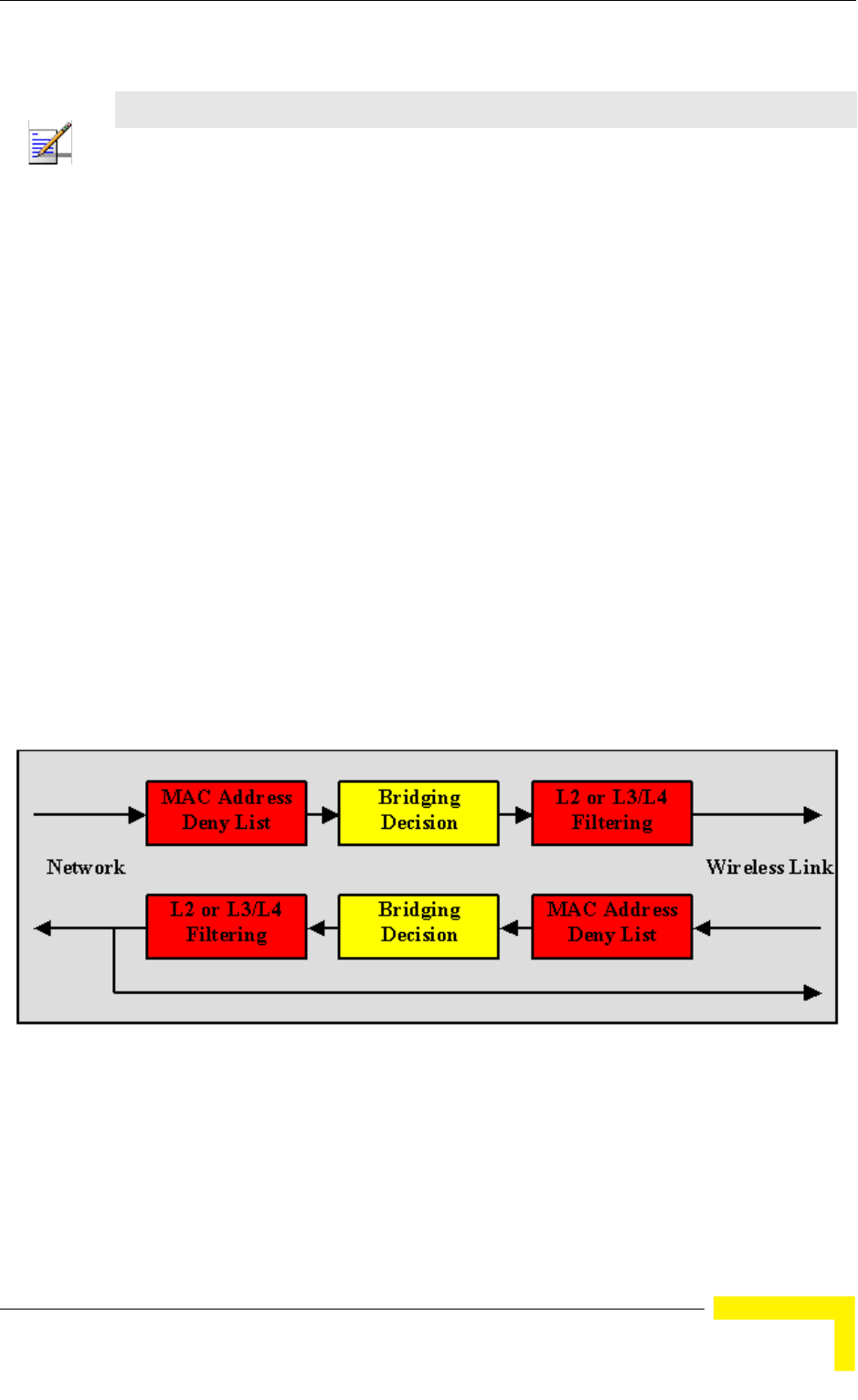
Services Menu
BreezeMAX Modular Base Station System Manual 207
4.11.2 Introduction to Filtering Features
The Filtering features allow a network operator to control the traffic in the system
by forwarding or discarding packets according to a set of rules based on multiple
allow/deny criteria. This provides both improved network security and better
utilization of the wireless medium.
The filtering is done at the base station, controlling the traffic between the
network and the wireless link. The filtering features enable:
Filtering packets arriving from the network interface (From Network Filtering),
using a set of either Layer 2 or Layer 3/Layer 4 Filtering Rules.
Filtering packets arriving from the wireless link (From Wireless Filtering),
using a set of either Layer 2 or Layer 3/Layer 4 Filtering Rules.
Discarding packets to/from specific MAC addresses (MAC Address Deny List).
This is applicable to MAC Addresses behind SUs.
The following figure describes the filtering functionality.
The filtering definition process includes the following steps:
1Defining list(s) of Filtering Rules. Each Filtering Rule defines a combination of
values for certain packet fields. Filtering Rules can be of 2 types: Layer 2
NOTE
The Filtering features are not applicable for units operating in IP CS Switching Mode.
Figure 4-2: Filtering Functionality

208 Operation
Chapter 4 - Operation and Administration
Filtering Rules (using fields of the Ethernet frame) and Layer 3/Layer 4
Filtering Rules (using fields of the IP and/or UDP/TCP headers).
2Associating each Interface (From Network, From Wireless Link) with a set of
either Layer 2 or Layer 3/Layer 4 filters from the relevant Filtering Rules lists,
and defining the action to be taken upon receiving a packet that matches any
of the selected Filtering Rules: Allow (forward) or Deny (discard).
4.11.3 Common Operations in Services Menu
Except for the General submenu, all submenus available in the Services menu
enable viewing, editing, deleting and adding applicable entities, such as
Subscribers, Services, Service Profiles, etc.
Some or all of the following options are available in all submenus of the Services
menu:
4.11.3.1 Show All
Select this option to see the current details of all entities in the applicable
submenu (Subscribers, Services, etc.).
4.11.3.2 Show by
This option enables selecting an entity by a specific identifier such as Name or
MAC Address. Select this option and enter the appropriate parameter's value to
access the menu for a selected entity. This will enable you to choose from the
following options:
Show: Select this option to view the details of the selected entity.
Update: Select this option to edit the details of the selected entity.
Delete: Select this option to remove the selected entity from the database.
4.11.3.3 Show List
Select this option to view all defined entities in the applicable submenu sorted by
the entity type ID (Subscriber ID, Service ID, etc.). The entity ID is an identifier
attached automatically to each new entity. You can select a specific entity by its
ID. This will open the Selected Entity menu with the Show, Update and Delete
options described above.

Services Menu
BreezeMAX Modular Base Station System Manual 209
4.11.3.4 Select
Select this option to select an entity by its Name. This will open the Selected
Entity menu with the Show, Update and Delete options described above.
4.11.3.5 Add
Select this option to add a new entity to the database.
4.11.4 The Services Menu
The Services menu includes the following options:
General (not applicable for units operating in IP CS Switching Mode)
Subscribers (not applicable for units operating in IP CS Switching Mode)
Services
Service Profile
Forwarding Rules
Priority Classifiers
QoS Profiles
Filtering Rules (not applicable for units operating in IP CS Switching Mode)
Interface Filtering (not applicable for units operating in IP CS Switching Mode)
MAC Addresses Deny List (not applicable for units operating in IP CS
Switching Mode)
4.11.4.1 General
The General menu includes general service parameters.
The General menu is not applicable for units operating in IP CS Switching Mode,
where the Service Mode is Always Advanced.
The General menu includes the following options:
4.11.4.1.1 Show
Select this option to view the current values/options of the General parameters.

210 Operation
Chapter 4 - Operation and Administration
4.11.4.1.2 Update
Select this option to update any of the General parameters. The General
parameters are:
4.11.4.1.2.1 Service Mode
The Service Mode of the Base Station.
The available options are:
1 - Advanced
2 - Quick
The default Service Mode is Quick (2).
For more information on Service Modes refer to Section 4.11.1.4.
4.11.4.1.2.2 Default L2/VoIP Service Profile
The default L2 or VoIP Service Profile to be used by temporary SUs in Quick Mode.
Available profiles - any of the L2 or VoIP Service Profiles existing in the database.
4.11.4.1.2.3 Default PPPoE Service Profile
The default PPPoE Service Profile to be used by temporary SUs in Quick Mode.
Available profiles - any of the PPPoE Service Profiles existing in the database.
4.11.4.2 Subscribers
The Subscribers menu enables defining new Subscribers, viewing or editing
details of previously defined Subscribers and removing Subscribers from the
database.
The Subscriber entity is applicable only to Permanent Services (services that are
defined in the NPU’s database and are provisioned to Permanent SUs).
The Subscribers database in the NPU can hold up to 1024 Subscribers.
The Subscriber menu is not applicable for units operating in IP CS Switching
Mode
The configurable Subscriber's parameters are:
4.11.4.2.1 Subscriber Name
This is the name of the subscriber, which must be unique for the entire network.
A Subscriber Name consists of up to 32 printable characters.
4.11.4.2.2 First Name
An optional parameter for information purposes.

Services Menu
BreezeMAX Modular Base Station System Manual 211
A First Name consists of up to 50 printable characters.
4.11.4.2.3 Last Name
An optional parameter for information purposes.
A Last Name consists of up to 50 printable characters.
4.11.4.2.4 Description
An optional parameter for information purposes.
A Description consists of up to 50 printable characters.
4.11.4.2.5 Admin Status
The administrative status of the Subscriber can be either Enabled or Disabled.
Select Disabled to disable all services to the Subscriber.
4.11.4.3 Services
There are two types of Services:
A Permanent Service is defined locally in the database of the Base Station and it
defines a Service to be provisioned to a Permanent SU.
A Temporary Service can only be granted to a Temporary SU. Typically, Temporary
Services are provided by a RADIUS Authentication Server. A Temporary Service
may also be granted by the Base Station (based on the Default Service Profiles)
when a RADIUS server is not available, or when the SU is rejected by the RADIUS
server, provided the unit operates in Quick Service Mode and the SU uses the
“quick” User Password “quickynikinyoky”. A Temporary Service is given a default
name of <SU Name>#<Number>. A Temporary Service cannot be defined, deleted
or edited locally using either the Monitor program or SNMP.
The Services menu enables viewing all Services, defining new permanent Services,
editing details of previously defined permanent Services and removing permanent
Services from the database.
NOTE
The proper process of removing a Service is:
1. Disable the Service (set the Admin Status to Disable)
2. Delete the Service.
If the Service is not disabled prior to being the deleted, VLAN ID included in the VLAN List of the
deleted Service may still be used by other Services to the same SU that use the same Forwarding
Rule as the deleted Service.

212 Operation
Chapter 4 - Operation and Administration
The Services database in the NPU (Base Station) can hold up to 4095 Services.
The Services menu also enables viewing and resetting the Service counters.
4.11.4.3.1 Service Parameters
The Service's parameters are:
4.11.4.3.1.1 Name
A Service Name consists of up to 32 printable characters.
A “temporary” Service is given a default name of <SU MAC Address>#<Number>.
4.11.4.3.1.2 Subscriber Name
The Subscriber to which the Service is allocated.
The Subscriber Name must be that of a Subscriber that exists in the database.
The Subscriber Name is not applicable to a “temporary” Service.
4.11.4.3.1.3 Service Profile Name
The Service Profile to be used in the Service.
The Service Profile Name must be that of a Service Profile that exists in the
database.
4.11.4.3.1.4 SU MAC Address
The MAC Address of the SU associated with the Service.
The SU MAC Address must be that of a Permanent SU that exists in the database.
The MAC Address can be changed (in Update option) only if the Admin status of
the Service is set to Disabled.
4.11.4.3.1.5 VLAN List
A list of VLAN IDs listing the VLAN IDs behind the SU associated with the
applicable Subscriber.
NOTE
Note the following changes that are applicable for units operating in IP CS Switching Mode:
Upon switching to IP CS Switching Mode, all previous Services are deleted from the database.
Services can only be accepted from AAA server, and are read-only (the Update option is not
applicable).
A Service includes the following configurable parameters: Service Name, Service Profile Name, SU
MAC Address, Service VPL ID (new parameter that defines the VLAN ID to be used in the network
side of the NPU) and Admin Status.
The following parameters are not applicable for IP Switching Mode Services: Subscriber Name,
VLAN List, Hybrid VLAN Mode, VLAN Classification Mode, Access VLAN.

Services Menu
BreezeMAX Modular Base Station System Manual 213
The list includes VLAN IDs, each one in the range of 0 to 4094, separated by
commas. Select null (empty string) for No VLAN. The VLAN List is not displayed in
Show menus if the list is empty.
When Hybrid VLAN Mode is Off, the VLAN List can include up to 16 VLAN IDs.
When Hybrid VLAN Mode is On, the VLAN List can include up to 15 VLAN IDs (the
16th entry is reserved for No VLAN).
The maximum total number of VLAN IDs behind a single SU is 16. (15 when there
is a Service with Hybrid VLAN Mode On is assigned to the SU).
Refer to Section 4.11.1.5 for guidelines regarding VLAN ID configuration.
4.11.4.3.1.6 Hybrid VLAN Mode
Hybrid VLAN Mode of operation enables classification of both tagged and
untagged packets or untagged packets only, according to the following rules:
Note that for each Service Type, a maximum of one Service that enables
forwarding of untagged packets can be assigned to an SU. Forwarding of untagged
packets is supported when either Hybrid VLAN Mode is On, or Hybrid VLAN Mode
is Off and the VLAN List is empty. It is not possible to define for the same SU two
Services of the same Service Type that enable forwarding of untagged packets.
However, the same SU and untagged packets can be associated with two Services
of different Service Types, excluding the combination of L2 Service and VoIP
Service.
4.11.4.3.1.7 VLAN Classification Mode
The VLAN Classification feature enables using VLAN ID (in addition to destination
MAC address) for classification of transparent service downlink traffic before
transmission to the destination MAC address. The VLAN Classification feature
supports applications where multiple VLANs are associated with a single MAC
address, allowing to assign different services to different VLANs.
Table 4-9: Hybrid VLAN Mode
Hybrid VLAN Mode VLAN List Forwarded Packets
Off Exists Only packets tagged with a VLAN ID that exists in the
VLAN List. VLAN List can include up to 16 entries.
Empty All (both untagged and tagged with any VLAN ID)
On Exists Untagged packets, and packets tagged with a VLAN ID
that exists in the VLAN List. VLAN List can include up to 15
entries.
Empty Only untagged frames.

214 Operation
Chapter 4 - Operation and Administration
VLAN Classification Mode can be set to On only if the following conditions are met:
The VLAN Transparency Mode of the applicable Service Profile is set to On.
A single VLAN ID is defined for the Service. This means that the allowed
combinations are:
Hybrid VLAN Mode is Off and the VLAN List includes a single VLAN ID.
Hybrid VLAN Mode is On and the VLAN List is empty.
All Services assigned to the same SU must be configured with the same VLAN
Classification Mode (Either On or Off).
4.11.4.3.1.8 Access VLAN
The Access VLAN parameter enables defining a VLAN ID to be used with untagged
packets received on the Ethernet port of the SU. This parameter is applicable only
for a transparent service (VLAN Transparency Mode is On) with Hybrid Mode set
to On, or a transparent service with Hybrid Mode set to Off and an empty VLAN
list.
A tag with the defined Access VLAN will be added by the NPU to untagged packets
in the uplink. The tag will be removed by the NPU from packets in the downlink.
For a multicast connection, the NPU will send in addition to the VLAN list the
single Access VLAN. The SU will be responsible to remove the Access VLAN if it is
received on a multicast connection.
A maximum of one Access VLAN can be defined per SU.
The range is from 1 to 4094 or null for no Access VLAN.
4.11.4.3.1.9 Admin Status
The administrative status of the Service can be either Enabled or Disabled. Select
Disabled to disable the Service.
4.11.4.3.1.10Operation Status
A read-only display of the operational status that is available in the Show menus
only. Up means that the Service is currently in use.
4.11.4.3.2 Performance
The Performance sub-menu enables viewing and resetting the connections'
counters of the Service. For each connection in each direction the following
information is displayed:
Connection ID and direction

Services Menu
BreezeMAX Modular Base Station System Manual 215
Connection Type: BE, NRT, RT or CG.
QoS Profile Parameters: The values of the relevant QoS Profile's parameters.
Bytes Submitted: The number of bytes submitted by upper layers to this
connection.
Bytes Transmitted: The number of bytes transmitted to the wireless port
through this connection, including retransmissions.
Bytes Retransmitted: The number of bytes retransmitted to the wireless port
through this connection.
Bytes Dropped: The number of bytes dropped from this connection due to
congestion in the wireless link. (identical to Bytes Discarded).
Bytes Discarded: The number of bytes discarded from this connection due to
congestion in the wireless link. (identical to Bytes Dropped).
Packets Submitted: The number of packets submitted by upper layers to this
connection.
Packets Transmitted: The number of packets transmitted to the wireless port
through this connection, excluding retransmissions.
Packets Dropped: The number of packets dropped from this connection due to
congestion in the wireless link. (identical to Packets Discarded).
Packets Discarded: The number of packets discarded from this connection due
to congestion in the wireless link. (identical to Packets Dropped).
Average Delay: The average packet delay in milliseconds, measured for this
connection over the last 15 seconds. The value is updated every 15 seconds.
Delay Variance: The variance (the standard deviation squared) of the packet
delay, in milliseconds squared, measured for this connection over the last 15
seconds. The value is updated every 15 seconds.
Maximum Delay: The maximum packet delay in milliseconds, measured for
this connection over the last 15 seconds. The value is updated every 15
seconds.

216 Operation
Chapter 4 - Operation and Administration
Data Loss Indicator (%): The percentage of dropped packets, out of the total
demand, measured for this connection over the last 15 seconds. The value is
updated every 15 seconds.
DLI (%) = 100 * (Packets Dropped) / (Packets Submitted)
CIR Utilization (%): The CIR utilization measured for an RT or NRT connection
over the last 15 seconds. Not applicable for BE and CG connections.
k = 100 x (the minimum between bytes transferred and CIR)/CIR is calculated
for each 1 second interval. CIR Utilization equals the average of k over the last
15 seconds, and may vary from 0 to 100. The value is updated every 15
seconds.
EIR Utilization (%): Excess Information Rate utilization measured for a BE or
NRT connection over the last 15 seconds. Not applicable for RT and CG
connections.
k=100 x (bytes transferred-CIR)/(MIR-CIR) is calculated for each 1 second
interval. In BE CIR = 0. The EIR Utilization equals the average of k over the
last 15 seconds, and may range from 0 to 100. The value is updated every 15
seconds.
Average Throughput (bits/s): The average throughput, in bits/second,
measured for this connection over the last 15 seconds. The value is updated
every 15 seconds.
4.11.4.4 Service Profiles
Each Service Profile defines the properties of the defined service. Each Service
Profile is associated with specific Forwarding Rule and Priority Classifier (Priority
Classifiers are not applicable to VoIP Service Profiles).
The Service Profile menu enables viewing all Service Profiles in the database,
defining new Service Profiles, editing details of previously defined Service Profiles
and removing Service Profiles from the database.

Services Menu
BreezeMAX Modular Base Station System Manual 217
The Service Profiles database can hold up to 1024 Service Profiles.
The Service Profile's parameters are:
4.11.4.4.1 Service Profile Name
A Service Profile Name consists of up to 32 printable characters.
4.11.4.4.2 Service Type
The Service Type of the Service Profile. The Service Type parameter is configurable
only when defining a new Service Profile (Add). It is not changeable.
The currently available Service Type options are:
1 - L2
2 - PPPoE
3 - VoIP
For more details refer to Section 4.11.1.2.
4.11.4.4.3 VLAN Transparency Mode
The VLAN Transparency Mode defines the method of transferring packets to the
operator's upstream network.
When set to On, data packets sent from the Base Station to the backbone will be
transferred transparently. The VPL ID parameter is not applicable to Service
Profiles with VLAN Transparency Mode On.
Also the Forwarding Rule selection parameter is not applicable to transparent
Service Profiles. All transparent Service Profiles share a single pre-configured
Forwarding Rule, and a pre-configured QoS Profile for multicasts. For details on
these profiles refer to Table 4-21 and Table 4-22. The pre-configured Transparent
Forwarding Rule can be modified but not deleted.
NOTE
Note the following changes that are applicable for units operating in IP CS Switching Mode:
Upon switching to IP CS Switching Mode, all previous Service Profiles are deleted from the
database.
There are two new Service Types in IP CS Switching Mode: IP CS Data and IP CS VoIP (the
previous L2, PPPoE and VoIPService Types used in Ethernet CS Switching Mode are not
applicable for IP CS Switching Mode.
Each Service Profile includes the following configurable parameters: Service Type (IP CS Data or
IP CS VoIP), Service Profile Name, Priority Classifier.
IP CS VoIP Service Profiles use the @@IP Mode VoIP@@ Forwarding Rule (available only in
relevant Show menus).
The following configurable parameters are not applicable for IP Switching Mode Service Profiles:
VLAN Transparency Mode, VPL ID, Priority Marking Mode, Priority Marking Value, Forwarding
Rule, Maximum Number of Voice Calls..

218 Operation
Chapter 4 - Operation and Administration
For tagged packets, the VPL ID will be their VLAN tag.
For untagged packets, the VPL ID will be None.
For packets received from the network, the forwarding decision will be according
to the packet's VPL ID. If the VPL ID is unknown (either None or not included in
the list of VPL IDs defined for any of the existing, non-transparent Service
Profiles), the system will assume this is a transparent VLAN packet (if at least one
transparent Service is defined) and transfer it with the original VLAN tag (or
untagged if there is no VLAN tag).
When set to Off, data packets sent from the Base Station to the backbone will be
transferred with a VLAN tag according to the VPL ID. The VLAN ID in tagged
frames arriving from the wireless network will be replaced by the VPL ID. For
packets received from the network, the forwarding decision will be according to
the Forwarding Rule defined in the Service Profile with a matching VPL ID.
To avoid conflicts, a transparent Service Profile cannot be assigned to a Service if
the Service's VLAN ID list includes a VLAN ID that is equal to any of the already
assigned VPL IDs.
4.11.4.4.4 VPL ID
A Virtual Private Link ID to be used in the backbone behind the Base Station. The
VPL ID parameter is applicable only to Service Profiles with VLAN Transparency
Mode Off.
To avoid conflicts, it is not allowed to define a VPL ID that is identical to any of the
VLAN IDs in the already assigned transparent Services (Services using a Service
Profile with VLAN Transparency Mode On).
Several Service Profiles may share the same VPL ID. However, the following rules
must be met:
NOTE
The combination of VLAN Transparency Service On, Hybrid VLAN Mode Off and an empty VLAN
List means that all packets are forwarded. This combination should be used only if the Service
Provider can ensure that there will not be conflicts between VLAN IDs used by devices behind the
SU and existing VPL IDs.
NOTE
The combination VLAN Transparency Mode On, Hybrid VLAN Mode On and an empty VLAN List
means that only untagged frames should be forwarded. Such a Service cannot be assigned if there
is an assigned non-transparent Service with VPL ID = None.

Services Menu
BreezeMAX Modular Base Station System Manual 219
Any number of L2 and/or VoIP Service Profiles may share the same VPL ID,
provided they all use the same Forwarding Rule.
Any number of PPPoE Service Profiles may share the same VPL ID, provided
they all use the same Forwarding Rule.
Any number of L2, VoIP and PPPoE Service Profiles may share the same VPL
ID, provided that all L2/VoIP Service Profiles use the same Forwarding Rule A,
and all PPPoE Service Profiles use the same Forwarding Rule B, where A and B
are different.
Available values are in the range of 0 to 4094 or null (empty string) for No VPL ID.
A value of 4095 is displayed for No VPL ID.
4.11.4.4.5 Priority Marking Mode
In some cases, the network operator may want to use the BreezeMAX system for
marking QoS classes, in order to provide network-wide QoS and enable the
upstream network to handle the traffic accordingly. Within the BreezeMAX
system, frames can be classified to QoS classes using Priority Classifiers, based
on either a DSCP header or 802,1p tag. This applies only in cases where an
external networking device marks the applicable fields. BreezeMAX also enables
marking data transmitted to the backbone network with either DSCP or 802.1p
values, where the marking is done per Service Profile. This marking overrides
marking performed by external devices behind the SU. Typically, Priority Marking
by the NPU will be used in the following cases:
The external networking equipment behind the SU does not use priority
marking.
The service provider does not trust the priority marking defined by the user's
equipment.
The service provider uses a priority marking type (DSCP or 802.1p) that differs
from the one used by the user's networking equipment.
The system supports three marking modes:
1Transparent Marking Mode (No Priority Marking): In this case, the system
should forward the frames to the uplink network without any changes.
If 802.1p classification is used at the SU, the frames will be transmitted to the
operator's network according to the following rules:

220 Operation
Chapter 4 - Operation and Administration
If VLAN Transparency Mode is Off, the frames will be forwarded with their
original 802.1p value and the configured VPL ID. If no VPL ID is configured
(VPL ID = Null), the 802.1p tags will not be forwarded.
If VLAN Transparency Mode is On, the frames will be forwarded without
any change (with the original 802.1p value and VLAN ID, if exists).
For DSCP classification at the SU:
If the VPL ID is configured (VLAN Transparency Mode Off), the NPU adds
an 802.1Q header with the configured VPL ID and 802.1p=0.
If VLAN Transparency Mode is On, The NPU adds a 802.1Q header with the
original VLAN ID (if exists).
Note that there may be a disparity between the DSCP values and the default
802.1p = 0 value.
2802.1p Marking Mode:
If VLAN Transparency Mode is Off, all frames are marked with the
configured VPL ID and the 802.1p Marking Value. If no VPL ID is
configured (VPL ID = None), the 802.1Q header will include a VLAN ID = 0.
If VLAN Transparency Mode is On, all frames are marked with the original
VLAN ID and the 802.1p Marking Value.
If 802.1p classification is used at the SU, the original 802.1p tags are
replaced by the configured 802.1p Marking Value.
If DSCP classification is used at the SU, an 802.1Q header is added, with
the configured VPL ID (if VLAN Transparency Mode is Off) or the original
VLAN ID (if VLAN Transparency Mode is On), and the 802.1p Marking
Value. The original DSCP bits are kept.
3DSCP Marking Mode: All frames are marked with the configured DSCP
Marking Values.
If 802.1p classification is used at the SU, the frames will be transmitted to the
operator's network according to the following rules:
NOTE
If the Priority Marking Value is set to 0, untagged packets (without VLAN ID) will be forwarded
without any change. This is applicable to transparent services and to to non-transparent services
with no VPL ID.
Services Menu
BreezeMAX Modular Base Station System Manual 221
If VLAN Transparency Mode is Off, the frames will be forwarded with their
original 802.1p value and the configured VPL ID. If no VPL ID is configured
(VPL ID = Null), the 802.1p tags will not be forwarded.
If VLAN Transparency Mode is On, the frames will be forwarded without
any change (with the original 802.1p value and VLAN ID, if exists).
If DSCP classification is used at the SU, the original DSCP bits will be replaced
by the configured DSCP Marking Value.
4.11.4.4.6 Priority Marking Value
The Priority Marking Value enables definition of the marking value for data frames
transmitted to the backbone, according to the configured Priority Marking Mode:
4.11.4.4.7 Forwarding Rule
The Forwarding Rule to be used by the Service Profile. The Forwarding Rule
parameter is not applicable to transparent Service Profiles (VLAN Transparency
Mode On), as all transparent Service Profiles share the same pre-defined
Forwarding Rule.
The Forwarding Rule must be one of the names that exist in the database after
being defined using the Forwarding Rule menu. The Service Type defined in the
selected Forwarding Rule must match the one defined for the Service Profile.
However, L2 Forwarding Rule can be used in a VoIP Service Profile, and vice versa.
NOTE
PPPoE frames can be marked only with 802.1p. DSCP marking for PPPoE services is not
supported.
In L2 Services, many protocols may be carried over Ethernet. As BreezeMAX bridges all these
protocols, there's no way to know what protocol type is encapsulated in Ethernet beforehand.
Consequently, if DSCP Marking is configured for L2, the BreezeMAX system uses DSCP
marking only for IP packets (e.g. Ethertype 0x0800). If 802.1p Marking is configured, it is used
for all frames.
Table 4-10: Priority Marking Values
Priority Marking Mode Priority Marking Values Range
Transparent Not Applicable
802.1p 0 - 7
DSCP 0 - 63

222 Operation
Chapter 4 - Operation and Administration
4.11.4.4.8 Priority Classifier (L2 and PPPoE Service Type)
The Priority Classifier to be used by the Service Profile. Not applicable for VoIP
Services.
The Priority Classifier must be one of the names that exist in the database, after
being defined using the Priority Classifier menu.
4.11.4.4.9 Maximum Number of Voice Calls (L2 and VoIP Service Type)
The Maximum Number of Voice Calls parameter sets the upper limit on the
number of simultaneous VoIP calls that can be supported by the Service using the
Service Profile. This parameter is applicable only for L2 and VoIP Service Profiles
and calls made by devices that support DRAP.
The available range is from 0 to 50 calls.
4.11.4.4.10 Service Profile Class
A read-only parameter (available only in Show menu). Currently the Class of all
Service Profiles is Local.
4.11.4.5 Forwarding Rules
The Forwarding Rule defines the features that affect forwarding and relaying of
data. Data in L2 and VoIP services may be switched only between the Services
that share the same Forwarding Rule. Data in PPPoE service can pass only
between the subscriber and an Access Concentrator behind the Base Station.
The Forwarding Rule menu enables viewing all Forwarding Rules in the database,
defining new Forwarding Rules, editing details of previously defined Forwarding
Rules and removing Forwarding Rules from the database.
NOTE
To properly support Call Waiting, the Maximum Number of Voice Calls should be configured to a
value that is twice the number of actual voice sessions that can be supported simultaneously.

Services Menu
BreezeMAX Modular Base Station System Manual 223
The Forwarding Rules database can hold up to 255 Forwarding Rules.
The Forwarding Rule's parameters are:
4.11.4.5.1 Forwarding Rule Name
A Forwarding Rule Name consists of up to 32 printable characters.
4.11.4.5.2 Service Type
The Service Type for which the Forwarding Rule is defined. The Service Type
parameter is configurable only when defining a new Service Profile (Add). It is not
changeable.
The currently available Service Type options are:
1 - L2
2 - PPPoE
3 - VoIP
For more details refer to Section 4.11.1.2.
4.11.4.5.3 Unicast Relaying (L2 Service Type)
The Unicast Relaying parameter determines whether the AU performs unicast
relaying. When the Unicast Relaying parameter is enabled, unicast packets
originating from devices on the wireless link can be transmitted back to the
wireless link devices. If disabled, these packets are not sent to the wireless link
even if they are intended for devices on the wireless link.
Unicast Relaying is applicable only to L2 Forwarding Rules. In all PPPoE
Forwarding Rules it is set to Disable. In all VoIP Forwarding Rules it is set to
Enable.
NOTE
Note the following changes that are applicable for units operating in IP CS Switching Mode:
Upon switching to IP CS Switching Mode, all previous Forwarding Rules are deleted from the
database.
A single Forwarding Rule named @@IP Mode VoIP@@ is provided for IP CS VoIP Service Type.
Certain parameters of this Forwarding Rule (except the Name and Service Type) can be updated.
This Forwarding Rule cannot be deleted. It is not possible to define additional Forwarding Rules.
The default values of the @@IP Mode VoIP@@ Forwarding Rule configurable parameters are:
Unicast Relaying: Enabled
Broadcast Relaying: Enabled
Unknown forwarding Policy: Forward
Multicast QoS Profile Name: @@IP Mode VoIP@@

224 Operation
Chapter 4 - Operation and Administration
4.11.4.5.4 Broadcast Relaying (L2 Service Type)
The Broadcast Relaying parameter determines whether the AU performs
broadcast relaying. When the Broadcast Relaying parameter is enabled, broadcast
packets originating from devices on the wireless link are transmitted by the AU
back to the wireless link devices, as well as to the backbone. If disabled, these
packets are sent only to the backbone and are not sent back to the wireless link.
Broadcast Relaying is applicable only to L2 Forwarding Rules. In all PPPoE
Forwarding Rules it is set to Disable. In all VoIP Forwarding Rules it is set to
Enable.
4.11.4.5.5 Unknown Forwarding Policy (L2 Services Type)
The Unknown Forwarding Policy parameter determines the mode of controlling
the flow of information from the backbone to the wireless media. Select from the
following options:
1 - Reject: The AU will transmit unicast packets only to those addresses that the
AU knows to exist on the wireless link side.
2 - Forward: Enables the transmission of all packets, except unicast packets sent
to addresses that the AU recognizes as being on its wired backbone side.
Unknown Forwarding Policy is applicable only to L2 Forwarding Rules. In all
PPPoE Forwarding Rules it is set to Reject. In all VoIP Forwarding Rules it is set to
Forward.
4.11.4.5.6 Multicast QoS Profile
The Multicast QoS Profile is the QoS Profile to be used for mulicast and broadcast
messages.
The QoS Profile must be one of the names that exist in the database after being
defined using the QoS Profile menu.
4.11.4.5.7 Forwarding Rule Class
A read-only parameter (available only in Show menu). Currently the Class of all
Forwarding Rules is Local.
4.11.4.6 Priority Classifiers
The Priority Classifier defines the QoS Profiles to be allocated to users/sessions
differentiated by DSCP or 802.1p priority classifiers. Priority Classifiers are not
applicable to VoIP Service Profiles.
Each Priority Classifier can define up to 4 uplink and 4 downlink QoS profiles.

Services Menu
BreezeMAX Modular Base Station System Manual 225
The Priority Classifier menu enables viewing all Priority Classifiers in the
database, defining new Priority Classifiers, editing details of previously defined
Priority Classifiers and removing Priority Classifiers from the database.
The Priority Classifiers database can hold up to 255 Priority Classifiers.
The Priority Classifier's parameters are:
4.11.4.6.1 Priority Classifier Name
A Priority Classifier Name consists of up to 32 printable characters.
4.11.4.6.2 Priority Type
The prioritization mechanism used by the Priority Classifier.
The available options are:
1 - DSCP
2 - 802.1p
4.11.4.6.3 Uplink Upper Priority Limits
The Uplink Upper Priority Limits parameter enables to define up to four ranges,
where each range may be assigned a different QoS Profile for uplink
communication. The list includes up to 4 numbers separated by commas, where
each number must be higher than its predecessor and the last number must be
the highest available for the applicable priority type (7 for 802.1p, 63 for DSCP).
Examples for acceptable lists:
DSCP Priority: [10,30,50,63]; [21,42,63]; [20,63]; [63].
802.1p Priority: [2,4,6,7]; [1,5,7]; [6,7]; [7].
NOTE
DSCP based Priority Classifiers are applicable only to IP or ARP traffic. It is not applicable to
PPPoE and other Ethernet type traffic.
If a Priority Classifier is not applicable for a certain traffic (e.g. DSCP based profile with PPPoE
traffic or 802.1p based profile with traffic that do not use VLAN tags), no prioritization scheme will be
in effect and quality of service will be determined by the first QoS Profile in the applicable lists.
NOTE
Note the following changes that are applicable for units operating in IP CS Switching Mode:
Upon switching to IP CS Switching Mode, all previous Priority Classifiers are deleted from the
database.
The Priority Type is not configurable, and it is always DSCP (802.1p prioritization is not available in
IP CS Switching Mode)

226 Operation
Chapter 4 - Operation and Administration
A ranges list of 21,42,63 means that packets with a priority from 0 to 21 will be
transmitted using the first QoS Profile defined in the Uplink QoS Profiles list (see
below), packets with a priority from 22 to 42 will be transmitted using the second
QoS Profile defined in the Uplink QoS Profiles list and packets with a priority
higher than 42 (43 63) will be transmitted using the third Uplink QoS Profile.
A ranges list that includes a single entry (63 for DSCP and 7 for 802.1p) means
that priority based classification is not used.
4.11.4.6.4 Uplink QoS Profiles
The Uplink QoS Profiles parameter enables to define up to four QoS Profiles,
where each entry is the QoS Profile associated with the applicable entry in the
Uplink Upper Priority Limits list. The list includes up to four QoS Profile Names,
where each name must be one of the names that exist in the database after being
defined using the QoS Profile menu. Each entry in the Uplink QoS Profiles list is
associated with the applicable entry in the Uplink Priority Ranges list.
4.11.4.6.5 Downlink Upper Priority Limits
The DownLink Upper Priority Limits list functionality is the same as that of the
Uplink Upper Priority Limits list, except that the ranges are defined for downlink
communication.
4.11.4.6.6 Downlink QoS Profiles
The Downlink QoS Profiles list functionality is the same as that of the Uplink QoS
Profiles list, except that the QoS Profiles are associated with the entries in the
Downlink Upper Priority Limits list.
4.11.4.6.7 Priority Classifier Class
A read-only parameter (available only in Show menu). Currently the Class of all
Priority Classifiers is Local.
4.11.4.7 QoS Profiles
The QoS Profile defines the Quality of Service parameters that are applicable when
the QoS Profile is used.
Different QoS Profile Types are available to support different service requirements:
Real-Time (RT) service is designed to meet the needs of Real Time Variable Bit
Rate like services characterized by requirements for guaranteed rate and delay
such as streaming video or audio. These services are dynamic in nature, but
offer periodic dedicated requests opportunities to meet real-time requirements.
Because the Subscriber Unit issues explicit requests, the protocol overhead
and latency is increased, but capacity is granted only according to the real

Services Menu
BreezeMAX Modular Base Station System Manual 227
needs of the connection. QoS Profile parameters include Committed
Information Rate (CIR) and Committed Time (CT).
Non-Real-Time (NRT) service is very similar to the Real-Time polling service
except that connections may utilize random access transmit opportunities for
sending bandwidth requests. These Non Real Time Variable Bit Rate services,
such as file transfer and Internet access with a minimum guaranteed rate, are
characterized by requirement for a guaranteed rate, but can tolerate longer
delays and are rather insensitive to jitter. QoS Profile parameters include
Committed Information Rate (CIR), Committed Time (CT) and Maximum
Information Rate (MIR) that limits the rate so that bandwidth intensive
services will not expand to occupy the full bandwidth.
Best Effort (BE) service is for services where neither throughput nor delay
guarantees are provided. The Subscriber Unit sends requests for bandwidth in
either random access slots or dedicated transmission opportunities. The
occurrence of dedicated opportunities is subject to network load, and the
Subscriber Unit cannot rely on their presence. Service parameters include
Maximum Information Rate (MIR). Committed Time (CT) is set to a fixed value
(Short) and cannot be configured.
Continuous Grant (CG) service is tailored for carrying constant bit rate (CBR)
real-time services characterized by fixed size data packets on a periodic basis
such as VoIP or E1/T1. The Base Station schedules regularly, in a preemptive
manner, grants of the size defined at connection setup, without an explicit
request from the Subscriber Unit. This eliminates the overhead and latency of
bandwidth requests in order to meet the delay and jitter requirements of the
underlying service. Service parameters include Packet Size (unsolicited grant
size) and Sampling Rate (grant interval).
The priorities of allocating bandwidth to connections are in accordance with the
QoS Type of the connections, in the following order:
1CG
2RT
3NRT
4BE
For each of the RT, NRT and BE connection, there is a second level of priorities
according to the Committed Time (CT), where connections with CT=Short gets the
highest priority and connections with CT=Long gets the lowest priority.

228 Operation
Chapter 4 - Operation and Administration
The QoS Profile menu enables viewing all QoS Profiles in the database, defining
new QoS Profiles, editing details of previously defined QoS Profiles and removing
QoS Profiles from the database.
The QoS Profiles database can hold up to 255 QoS Profiles.
The available QoS Profile parameters depend on the QoS Type. The QoS Profile's
parameters are:
4.11.4.7.1 QoS Profile Name
A QoS Profile Name consists of up to 32 printable characters.
4.11.4.7.2 QoS Type
The QoS Type that defines the QoS parameters that are applicable to the service.
The available options are:
1 - CG (Continuous Grant)
2 - RT (Real Time)
3 - NRT (Non real time)
4 - BE (Best Effort)
4.11.4.7.3 CT (RT and NRT QoS Types)
The CT (Committed Time) parameter defines the time window over which the
information rate is averaged to ensure compliance with the CIR or MIR parameter.
It is used also to prioritize bandwidth allocation to connections, where for each
QoS Type, connections with a shorter CT get higher priority.
The available options are Short (50 mS), Medium (100 mS), and Long (200 mS).
NOTE
Note the following changes that are applicable for units operating in IP CS Switching Mode:
Upon switching to IP CS Switching Mode, all previous QoS Profiles are deleted from the database.
A single QoS Profile named @@IP Mode VoIP@@ is provided for IP CS VoIP Service Type. All
parameters of this QoS Profile can be updated, and it can also be deleted from the database.
Additional QoS Profiles can be defined.
The default values of the @@IP Mode VoIP@@ QoS Profile configurable parameters are:
Name: @@IP Mode VoIP@@
QoS Type: BE
MIR (Kbps): 128

Services Menu
BreezeMAX Modular Base Station System Manual 229
4.11.4.7.4 CIR (RT and NRT QoS Types)
CIR is the information transfer rate that the system is committed to transfer
under normal conditions. The rate is averaged over a minimum increment of time,
which is defined by the CT parameter.
The range is from 0 to 12,000 Kbps.
4.11.4.7.5 MIR (NRT and BE QoS Types)
MIR is the maximum information rate that the system will allow for the
connection. The rate is averaged over a minimum increment of time, which is
defined by the CT parameter.
The range is from 1 to 12,000 Kbps.
MIR cannot be lower than CIR (applicable to NRT QoS type).
4.11.4.7.6 Packet Size (CG QoS Type)
The Packet Size parameter defines the amount of data in bytes that is expected for
each grant.
The range is from 64 to 1550 (bytes).
4.11.4.7.7 Sample Interval (CG QoS Type)
The Sample Interval parameter defines the time in milliseconds between two
successive grants (inter arrival time).
The range is from 5 to 100 (milliseconds).
4.11.4.7.8 QoS Profile Class
A read-only parameter (available only in Show menu). Currently the Class of all
QoS Profiles is Local.
4.11.4.8 Filtering Rules
The Filtering Rules menu enables defining L2 Filtering Rules and L3/L4 Filtering
Rules.
The Filtering Rules option is not applicable for units operating in IP CS Switching
Mode.
4.11.4.8.1 L2 Filtering Rules
An L2 (Layer 2) Filtering Rule includes the MAC Address and Ethertype. A range of
MAC Addresses can be defined for either the Source or Destination MAC Address
field. It is possible to define "Any" for either the MAC Address or Ethertype field
(but not for both fields).
The L2 Filtering Rules menu enables defining new L2 Filtering Rule, viewing
details of previously defined L2 Filtering Rules and removing L2 Filtering Rules

230 Operation
Chapter 4 - Operation and Administration
from the database. It is not possible to edit the parameters of an existing L2
Filtering Rule. The database can hold up to 255 L2 Filtering Rules.
The configurable L2 Filtering Rule parameters are:
4.11.4.8.1.1 Rule Name
The name of the L2 Rule. The L2 Rule Name is a string of 1 to 32 printable
characters.
4.11.4.8.1.2 MAC Address
The base MAC Address that is used together with the MAC Address Mask to define
a range of MAC addresses. A string of 6 octets (where each octet is represented by
two hexadecimal numbers) separated by dashes ("-"). An empty entry means
"Any". An "Any" MAC Address means that the filter is defined only by the
Ethertype field.
4.11.4.8.1.3 MAC Address Mask
The mask that is used together with the MAC Address to define a range of MAC
addresses. A string of 6 octets (where each octet is represented by two
hexadecimal numbers) separated by dashes ("-"). In a binary representation the
string must comprise a series of contiguous binary '1's starting from the MSB,
followed by a series of contiguous binary '0's (if the range includes more than a
single address). The MAC Address Mask parameter is not applicable for an "Any"
MAC Address.
4.11.4.8.1.4 MAC Address Direction
The direction (Source or Destination) of the MAC Address. Indicates whether the
range defined by the MAC Address and MAC Address Mask is for the Source MAC
Address field or the Destination MAC Address field in the Ethernet frame. The
MAC Address Direction parameter is not applicable to "Any" MAC Address.
4.11.4.8.1.5 Ethertype
The Ethertype of the Ethernet frame. The Ethertype is defined by 4 hexadecimal
digits. An empty entry means "Any" and is applicable only if a MAC Address range
is defined (the combination of "Any" for both the MAC Address and Ethertype is
not allowed).
4.11.4.8.2 L3/L4 Filtering Rules
An L3/L4 (Layer 3/Layer 4) Filtering Rule includes the IP Address and Protocol. A
range of IP Addresses can be defined for either the Source or Destination IP
Address field. It is possible to define "Any" for either the IP Address or Protocol
field (but not for both fields). If the specified Protocol is either TCP (6) or UDP (17),
either the Source or Destination Port can be defined. It is also possible to define
"Any" Port. The direction is applicable for both IP Address and Port.

Services Menu
BreezeMAX Modular Base Station System Manual 231
The L3/L4 Filtering Rules menu enables defining new L3/L4 Filtering Rule,
viewing details of previously defined L3/L4 Filtering Rules and removing L3/L4
Filtering Rules from the database. It is not possible to edit the parameters of an
existing L3/L4 Filtering Rule. The database can hold up to 255 L3/L4 Filtering
Rules.
The configurable L3/L4 Filtering Rule parameters are:
4.11.4.8.2.1 Rule Name
The name of the L3/L4 Rule. The L3/L4 Rule Name is a string of 1 to 32 printable
characters.
4.11.4.8.2.2 IP Address
The base IP Address that is used together with the IP Address Mask to define a
range of IP addresses. A string of 4 decimal numbers (where each number is in the
range from 1 to 255) separated by dashes ("-"). An empty entry means "Any". An
"Any" IP Address means that the filter is defined only by the Protocol field (and
optionally by the Port and Port Direction for UDP or TCP protocols).
4.11.4.8.2.3 IP Address Mask
The mask that is used together with the IP Address to define a range of IP
addresses. A string of 4 decimal numbers (where each number is in the range
from 1 to 255) separated by dashes ("-"). In a binary representation, the string
must comprise a series of contiguous binary '1's starting from the MSB, followed
by a series of contiguous binary '0's (if the range includes more than a single
address). The IP Address Mask parameter is not applicable to an "Any" IP Address.
4.11.4.8.2.4 IP Address Direction
The direction (Source or Destination) of the IP Address. Indicates whether the
range defined by the IP Address and IP Address Mask is for the Source IP Address
field or the Destination IP Address field in the IP frame. The IP Address Direction
parameter is not applicable to "Any" IP Address.
4.11.4.8.2.5 Protocol
The protocol of the IP packet. The Protocol is defined by a decimal number from 0
to 254. An empty entry means "Any" and is applicable only if an IP Address range
is defined (the combination of "Any" for both the IP Address and Protocol is not
allowed).
4.11.4.8.2.6 Port
The TDP/UCP port number, which is applicable only if the Protocol parameter is
configured to a value of either 6 (TCP) or 17 (UDP). The Port is defined by a
number in the range from 0 to 65534. An empty entry means "Any" port.

232 Operation
Chapter 4 - Operation and Administration
4.11.4.8.2.7 Port Direction
The direction (Source or Destination) of the Port. Indicates whether the Port
number is for the Source Port field or the Destination Port field in the IP frame.
The Port Direction parameter is not applicable to "Any" Port.
4.11.4.9 Interface Filtering
The Interface Filtering menu enables viewing and editing the filtering mechanisms
to be used on frames received from the network (From Network Filtering) and from
the wireless link (From Wireless Filtering).
The Interface Filtering menu also enables viewing and resetting the Filtering Rules
Counters, which display for each of the applicable rules the number of frames
matching the rule, accumulated since the last reset. In addition, there is a Non
Matching counter, displaying the number of frames that did not match any of the
relevant rules. The counters will be reset also after changing the Active Rule Type
or disabling the Admin Status.
The Interface Filtering option is not applicable for units operating in IP CS
Switching Mode.
For each of the interfaces, the configurable parameters are:
4.11.4.9.1 L2 Filtering Rules List
The L2 Filtering Rules List submenu enables viewing details on the L2 Filtering
Rules assigned to the interface, adding Rules (from the L2 Filtering Rules lists) to
the list of Rules assigned to the interface, and deleting one or all Rules from the
list. It also enables viewing/resetting the counter for a selected Rule. The counter
displays the number of frames matching the Rule, accumulated since the last
reset. The counter will be reset also after changing the Active Rule Type or
disabling the Admin Status.
4.11.4.9.2 L3/L4 Filtering Rules List
The L3/L4 Filtering Rules List submenu enables viewing details on the L3/L4
Filtering Rules assigned to the interface, adding Rules (from the L3/L4 Filtering
Rules lists) to the list of Rules assigned to the interface, and deleting one or all
Rules from the list. It also enables viewing/resetting the counter for a selected
Rule. The counter displays the number of frames matching the Rule, accumulated
since the last reset. The counter will be reset also after changing the Active Rule
Type or disabling the Admin Status.
4.11.4.9.3 Active Rule Type
The Active Rule Type parameter defines which of the Filtering Rules List is used.
The available options are Layer 2 and Layer 3/4.

Services Menu
BreezeMAX Modular Base Station System Manual 233
The default option is Layer 2.
4.11.4.9.4 Admin Status
The Admin Status parameter defines whether the filtering mechanism is enabled
or disabled.
The default option is Disabled.
4.11.4.9.5 Default Action
The Default Action parameter defines the action to be taken for a frame matching
any of the applicable Filtering Rules: Deny (discard) or Allow (forward).
If the Default Action is Allow, all frames matching any of the applicable Filtering
Rules will be forwarded, and all other frames will be discarded.
If the Default Action is Deny, all frames matching any of the applicable Filtering
Rules will be discarded, and all other frames will be forwarded.
The default option is Deny.
The menu also enables viewing and resetting the Non Matching Counter, which
displays the total number of frames that did not match any of the applicable
Filtering Rules, accumulated since the last reset. The counter will be reset also
after changing the Active Rule Type or disabling the Admin Status.
NOTE
L3/L4 Filtering Rules are applicable only to IP packets. If the Default Action is Allow, non-IP packets
will be forwarded although they do not match any of the applicable Forwarding Rules.
NOTE
Broadcasts and Management frames received from the network, whose destination is the NPU,
are never filtered.
ARP messages will be forwarded automatically if the following conditions are met:
1. Active Rule Type is L3/L4.
2. The L3/L4 Filtering Rules List includes at least one L4 Filtering Rule (a defined protocol).
3. The Default Action is Allow.
This is applicable for both interfaces.

234 Operation
Chapter 4 - Operation and Administration
4.11.4.10 Filtering Examples
Example 1: Block All Broadcasts Except ARP and PPPoE
To block all broadcasts except ARP and PPPoE, define an L2 Filtering Rule that
includes all other broadcasts. Typically this includes broadcasts with IP
Ethertype. The parameters of this rule will be:
MAC Address: FF-FF-FF-FF-FF-FF
MAC Address Mask: FF-FF-FF-FF-FF-FF
MAC Address Direction: Destination
Ethertype: 800
Assuming the intention is to block this broadcast in both directions, this Filtering
Rule should be included in the L2 Filtering Rules List of both the From Network
Filtering and the From Wireless Filtering. In addition, for both Interfaces the
following configuration should be defined:
Active Rule Type: Layer 2
Admin Status: Enabled
Default Action: Deny
If broadcasts using other Ethertypes except IP, ARP and PPPoE are excepted,
similar Layer 2 Filtering Rules should be defined for these Ethertypes (with the
broadcast MAC Address), and these rules should be added to the applicable Layer
2 Filtering Rules Lists.
Example 2: Block DHCP Server behind SU
To prevent the use of a DHCP server behind an SU, define the following L3/L4
Filtering Rule:
IP Address: Any (empty)
Protocol: 17 (UDP)
Port: 67 (the source port of the DHCP server)

Services Menu
BreezeMAX Modular Base Station System Manual 235
Port Direction: Source
This Filtering Rule should be included in the L3/L4 Filtering Rules List of the
From Wireless Filtering. In addition, the following configuration should be defined
for the From Wireless Filtering Interface:
Active Rule Type: Layer 3/4
Admin Status: Enabled
Default Action: Deny
4.11.4.11 MAC Addresses Deny List
The MAC Addresses Deny List menu enables viewing and editing the MAC
Addresses Deny List. This list is used to deny services to MAC Addresses behind
SUs. Uplink frames whose source MAC address matches any of the entries in the
list and downlink frames whose destination MAC address matches any of the
entries in the list will be discarded.
The MAC Addresses Deny List menu also enables viewing and resetting the MAC
Addresses Deny List Counters, which display for each of the entries in the list the
number of frames that were discarded because they match the entry,
accumulated since the last reset.
The MAC Addresses Deny List option is not applicable for units operating in IP CS
Switching Mode.
4.11.5 Defining Service Profiles
The process of defining completely new Service Profiles should be done "from
bottom up", as each entity in the process is defined using one or more "lower level"
entities.
1Define the QoS profiles that should be available for the required Priority
Classifier (Uplink/Downlink QoS Profiles) and for the required Forwarding
Rule (Multicast QoS Profile).
2Define the Priority Classifier that should be available for the required Service
Profile. All QoS Profiles required for the Uplink/Downlink QoS profiles list
must be defined in advance.
To define a new Service Profile "from scratch":

236 Operation
Chapter 4 - Operation and Administration
3Define the Forwarding Rule that should be available for the required Service
Profile. The QoS Profile required for the Multicast QoS Profile parameter must
be defined in advance.
4Define the Service Profile. The required Priority Classifier and Forwarding Rule
must be defined in advance.
5Once there are various QoS Profiles, Priority Classifiers and Forwarding Rules
in the database, you can skip one or more of the steps 1 to 3.
4.11.6 Defining Local (Permanent) Services
1Verify that the necessary Service Profile(s) are available in the database.
2Define the relevant Subscriber.
3Verify that the applicable SU is defined.
4Use existing Subscriber Name, SU MAC Address and Service Profile Name to
define the required Service.
Once there are various Subscribers and SUs in the database, you can skip one or
more of the steps 2 to 3.
4.11.7 Defining RADIUS Based Services
1Verify that the necessary Service Profiles are available in the database of the
relevant Base Station(s).
2The Users List of the server must include the default User Name and Password
of the NPU (both are KeepAliveUserNameAndPassword).
3The format of the each Service in the ID Filter in the RADIUS Authentication
server(s) is n:v:h:a:c; The ID Filter may include up to 5 Services, separated by
“;”: s1;s2;...
n = Service Profile Name
v=<VLAN List>. v=<> is an empty VLAN list.
h=ON or OFF, indicating the configured Hybrid VLAN Mode.
a=<OFF or ON, VLAN ID>, indicating the configured Access VLAN Mode,
and the Access VLAN ID for Access VLAN ON.
c=ON/OFF, indicating the configured VLAN Classification Mode.
To define a new Service "from scratch":

Services Menu
BreezeMAX Modular Base Station System Manual 237
Example 1: n=be_96:v=<2,4,5>:h=ON:a=<ON,100>:c=ON;
Example 2: n=be_128:v=<22>:h=OFF:a=<OFF>:c=OFF;
4.11.8 Pre-configured Profiles
At manufacturing stage, each NPU is configured with a set of pre configured
Profiles. Certain parameters of these Profiles may be modified to reflect specific
implementation requirements. When the software version is upgraded, these
pre-configured Profiles will not be installed again in the NPU. This is to prevent
configuration problems from occurring if the modified Profiles differ from the
factory loaded Profiles.
Note that upon resetting to NPU to its default configuration (Set Factory Defaults),
pre-configured Profiles that were modified are not affected.
The pre-configured profiles are not available in IP CS Switching Mode.
The pre-configured Service Profiles are:
Internet Access L2 - for basic Internet Access service with Best Effort QoS,
utilizing L2 Service Type. This is the recommended Default Service Profile for
Quick Mode.
Internet Access PPPoE - for basic Internet Access service with Best Effort
QoS, utilizing PPPoE Service Type.
Gold, Silver and Bronze Teleworking - for teleworking applications with
different QoS requirements. The pre-configured Teleworking Services are
asymmetric: DL Rate > UL Rate.
Gold, Silver and Bronze LAN-to-LAN - for LAN-to LAN applications with
different QoS requirements. The pre-configured LAN-to-LAN Services are
symmetric: DL rate = UL rate.
VoIP Service Profiles - for DRAP-based gateways. Two pre configured VoIP
service Profiles are defined; VoIP 1V for gateways with a single POTS interface,
and VoIP 2V for fully supporting gateways for 2 POTS interfaces.
Service Profiles for Generic (non-DRAP) VoIP Devices:
1 POTS Basic VoIP G.729: 1 POTS, no Fax, G.729 codec with a 20
milliseconds sample interval, no priority marking.

238 Operation
Chapter 4 - Operation and Administration
1 POTS Advanced VoIP G.729: 1 POTS, T.38 Fax, G.729 codec with a 20
milliseconds sample interval, DSCP priority marking.
1 POTS Basic VoIP G.711: 1 POTS, no Fax, G.711 codec with a 20
milliseconds sample interval, no priority marking.
1 POTS Advanced VoIP G.711: 1 POTS, T.38 Fax, G.729 codec with a 20
milliseconds sample interval, DSCP priority marking.
For more details on defining Service Profiles for Generic (3rd party) VoIP devices,
refer to Appendix B.
Except for the Basic PPPoE Internet Access pre-configured Service Profiles, all
pre-configured Data Service Profiles use L2 Service Type to ensure transport of all
L2 and L3 protocols.
It is recommended to use the L2 Best Effort Internet Access pre configured Service
Profile as the Default Data Service Profile in Quick Mode.
The following tables provide details on the pre-configured Service Profiles,
Forwarding Rules, Priority Classifiers and QoS Profiles.
In all pre-configured Data Service Profiles, the Priority Marking Mode is set to
Transparent and the Maximum Number of Voice Calls is 0.
* VPL IDs are assigned arbitrary values and should be configured in accordance
with specific network implementation, taking into account the considerations
described in Section 4.11.1.5.
As Internet Access L2 is the recommended Default Data Service Profile, a VPL ID =
None is used to ensure availability of basic data services in Quick Mode.
Table 4-11: Pre-Configured Data Service Profiles
Name Service Type VPL ID* Forwarding Rule Priority Classifier
Internet Access L2 L2 Null Internet Access L2 BE Asymmetric
Internet Access PPPoE PPPoE 11 Internet Access PPPoE BE Asymmetric
Gold Teleworking L2 12 Gold Teleworking Gold Asymmetric
Silver Teleworking L2 13 Silver Teleworking Silver Asymmetric
Bronze Teleworking L2 14 Bronze Teleworking Bronze Asymmetric
Gold LAN-to-LAN L2 15 Gold LAN-to-LAN Gold Symmetric
Silver LAN-to-LAN L2 16 Silver LAN-to-LAN Silver Symmetric
Bronze LAN-to-LAN L2 17 Bronze LAN-to-LAN Bronze Symmetric

Services Menu
BreezeMAX Modular Base Station System Manual 239
Table 4-12: Pre-Configured Forwarding Rules for Data Service
Name Service
Type Unicast
relaying Broadcast
Relaying Unknown
forwarding
Policy
Multicast QoS
Internet Access L2 L2 Disable Disable Forward BE 750
Internet Access
PPPoE
PPPoE Disable (hard
coded)
Disable (hard
coded)
Forward (hard
coded)
BE 750
Gold Teleworking L2 Disable Disable Forward NRT 1500/1750
Silver Teleworking L2 Disable Disable Forward NRT 1000/1150
Bronze Teleworking L2 Disable Disable Forward NRT 750/850
Gold LAN-to-LAN L2 Enable Enable Forward NRT 1500/1750
Silver LAN-to-LAN L2 Enable Enable Forward NRT 1000/1150
Bronze LAN-to-LAN L2 Enable Enable Forward NRT 750/850
Table 4-13: Pre-Configured Priority Classifiers for Data Services
Name Type Uplink
Priority
Ranges
Uplink QoS
Profiles Downlink
Priority Ranges Downlink QoS
Profiles
BE Asymmetric 802.1p 7 BE 96 7 BE 750
Gold Asymmetric 802.1p 7 NRT 128/192 7 NRT 1500/1750
Silver Asymmetric 802.1p 7 NRT 96/128 7 NRT 1000/1150
Bronze Asymmetric 802.1p 7 NRT 96/128 7 NRT 750/850
Gold Symmetric 802.1p 7 NRT 1500/1750 7 NRT 1500/1750
Silver Symmetric 802.1p 7 NRT 1000/1150 7 NRT 1000/1150
Bronze Symmetric 802.1p 7 NRT 750/850 7 NRT 750/850
240 Operation
Chapter 4 - Operation and Administration
* Although Medium CT may be indicated for these BE QoS Profiles (legacy from
previous versions), the actual CT is Short.
* VPL IDs are assigned arbitrary values and should be configured in accordance
with specific network implementation, taking into account the considerations
described in Section 4.11.1.5.
** To properly support Call Waiting, an additional connection must be available.
Thus, the Maximum Number of Voice Calls is twice the maximum expected
number of actual voice sessions.
Table 4-14: Pre-Configured QoS Profiles for Data Services
Name Type CIR (Kbps) MIR (Kbps) CT
BE 96 Best Effort NA 96 Short*
BE 750 Best Effort NA 750 Short*
NRT 96/128 Non Real Time 96 128 Medium
NRT 128/192 Non Real Time 128 192 Medium
NRT 750/850 Non Real Time 750 850 Medium
NRT 1000/1150 Non Real Time 1000 1150 Medium
NRT 1500/1750 Non Real Time 1500 1750 Medium
Table 4-15: Pre-Configured VoIP Service Profiles (for DRAP-based Gateways)
Name Service
Type VPL
ID* Priority
Marking Mode Maximum Number
of Voice Calls** Forwarding
Rule
VoIP 1V VoIP 18 Transparent 2 VoIP
VoIP 2V VoIP 18 Transparent 4 VoIP
Table 4-16: Pre-Configured Service Profiles for Generic (non-DRAP) VoIP Services
Name Service
Type VPL ID* Forwarding
Rule Priority Classifier
1 POTS Basic VoIP G.729 L2 19 VoIP 1 POTS Basic VoIP G.729
1 POTS Advanced VoIP
G.729
L2 19 VoIP 1 POTS Advanced VoIP
G.729
1 POTS Basic VoIP G.711 L2 19 VoIP 1 POTS Basic VoIP G.711
1 POTS Advanced VoIP
G.711
L2 19 VoIP 1 POTS Advanced VoIP
G.711

Services Menu
BreezeMAX Modular Base Station System Manual 241
In all pre-configured Service Profiles for generic VoIP services, the Priority Marking
Mode is set to Transparent and the Maximum Number of Voice Calls is 0.
* VPL IDs are assigned arbitrary values and should be configured in accordance
with specific network implementation, taking into account the considerations
described in Section 4.11.1.5.
All pre-configured Service profiles for VoIP (DRAP-based VoIP Services and
Generic (3rd party) VoIP Services share the same pre-configured Forwarding Rule,
to enable direct communication between all users of VoIP Services, regardless of
the gateway type and other possible differences in the Service Profiles.
Table 4-17: Pre-Configured Forwarding Rule for VoIP Services
Name Service
Type Unicast
Relaying Broadcast
Relaying Unknown
forwarding Policy Multicast
QoS
VoIP VoIP Enable (hard
coded)
Enable (hard
coded)
Forward (hard
coded)
BE 128
Table 4-18: Pre-Configured Priority Classifiers for Generic (non-DRAP) VoIP Service
Name Type Uplink
Priority
Ranges
Uplink
QoS
Profiles
Downlink
Priority
Ranges
Downlink
QoS Profiles
1 POTS Basic VoIP G.729 DSCP 63 CG 47 63 CG 47
1 POTS Advanced VoIP
G.729
DSCP 0 BE 64 0 BE 64
26 RT 6 26 RT 6
63 CG 38 63 CG 38
1 POTS Basic VoIP G.711 DSCP 63 CG 108 63 CG 108
1 POTS Advanced VoIP
G.711
DSCP 0 BE 64 0 BE 64
26 RT 11 26 RT 11
63 CG 88 63 CG 88
242 Operation
Chapter 4 - Operation and Administration
* Although Medium CT may be indicated for these BE QoS Profiles (legacy from
previous versions), the actual CT is Short.
The following tables provide details on the pre-configured Profiles used for
Transparent Services (VLAN Transparency Mode is ON):
* Although Long CT may be indicated for this BE QoS Profile (legacy from previous
versions), the actual CT is Short.
Table 4-19: Pre-Configured BE and RT QoS Profile for VoIP Services
Name Type CIR (Kbps) MIR (Kbps) CT
BE 64 Best Effort NA 64 Short*
BE 128 Best Effort NA 128 Short*
RT 6 Real Time 6 NA Short
RT 11 Real Time 11 NA Short
Table 4-20: Pre-Configured CG QoS Profile for Generic (non-DRAP) VoIP Services
Name Type Packet Size (Bytes) Sample Interval (msec)
CG 38 Continuous Grant 94 20
CG 47 Continuous Grant 117 20
CG 88 Continuous Grant 218 20
CG 108 Continuous Grant 270 20
Table 4-21: Pre-Configured Forwarding Rule for Transparent Services
Name Service
Type Unicast
Relaying Broadcast
Relaying Unknown
forwarding
Policy
Multicast QoS
@@Transparent@@ L2 Enable Enable Forward @@Transparent@@
NOTE
The name of the Transparent Forwarding Rule cannot be edited.
Table 4-22: Pre-Configured QoS Profile for Transparent Services
Name Type CIR (Kbps) MIR (Kbps) CT
@@Transparent@@ Best Effort NA 128 Short*

NPU Parameters Summary
BreezeMAX Modular Base Station System Manual 243
4.12 NPU Parameters Summary
Table 4-23: NPU Monitor Parameters Summary
Parameter Range Default Run-Time
Updated
Base Station Configuration Parameters
Device Name Up to 255 printable characters Null Yes
Device Location Up to 255 printable characters Null Yes
Switching Mode 1 - Ethernet CS
2 - IP CS
Ethernet CS No
ATPC Enable/Disable 1 - Disable
2 - Enable
Disable is temporary until next reset of the
NPU or AUs
Enable Yes
Optimal Uplink RSSI (dBm) -90 to -60 (-80 to -74 at the AUs) -73
(-74 at the AUs)
Yes
Operator ID X.X.X
X: 0-255
186.190.0 No
Cell ID X.X
X: 0-255
0.250 No
Duplex Mode FDD, TDD
Only TDD spplicable to current version)
TDD No
DL-UL Ratio 1: 65-35 (%)
2: 60-40 (%)
3: 55-45 (%)
4: 50-50 (%)
5: 45-55 (%)
6: 40-60 (%)
7: 35-65 (%)
(See Section 4.5.2.6.2 for limitations)
50-50 (%) No
External 1PPS Clock 1 - Disable
2 - Enable
Enable No

244 Operation
Chapter 4 - Operation and Administration
External 16MHz Clock 1 - Disable
2 - Enable
Disable No
Chain
Chain Number 1 - 1500 0 (not defined
yet-must be
defined)
No
GPS Protocol 0 - None
1 - Trimble
2 - Symmetricom
Timble No
Time Zone Offset From UTC -12:00 to +13:00 +02:00 Yes
Stop Tx After Hold Over
Timeout
1 - Disable
2 - Enable
Disable Yes
Hold Over Passed Timeout 0 - 2880 (minutes) 30 (minutes) Yes
Base Station Alarms and Traps
Traps Display Filter-Minimum
Severity
1 - Critical
2 - Major
3 - Minor
4 - Warning
5 - Info
Info Yes
Traps Display Filter-Days 1 - 31 days 31 days Yes
Traps Configuration-Admin
Status
1 - Disable
2 - Enable
Enable Yes
Trap Configuration-Severity 1 - Critical
2 - Major
3 - Minor
4 - Warning
5 - Info
Depends on trap Yes
Trap Configuration-Suppression
Interval
0 - 86,400 (seconds).
0 means no suppression
0 (no
suppression)
Yes
RADIUS General Parameters
Table 4-23: NPU Monitor Parameters Summary
Parameter Range Default Run-Time
Updated

NPU Parameters Summary
BreezeMAX Modular Base Station System Manual 245
Shared Secret Up to 16 printable characters, case
sensitive. Available only via Monitor.
null (must be
defined)
Yes
Retry Interval (sec) 1-5 (seconds) 5 (seconds) Yes
Maximum Number of Retries 0-5 5 Yes
Keep Alive Timeout (sec) 60-180 (seconds) 60 (seconds) Yes
RADIUS Authentication (up to two servers)
IP Address IP address null Yes
UDP Port 1-65535 1812 Yes
Server Status 1 - Primary
2 - Secondary
(Only one server can be Primary)
Yes
RADIUS Accounting (up to two servers)
IP Address IP address null Yes
UDP Port 1-65535 1813 Yes
Server Status 1 - Primary
2 - Secondary
(Only one server can be Primary)
Yes
NPU Parameters
Administrator Password Up to 16 printable characters, case
sensitive
admin Yes
Installer Password Up to 16 printable characters, case
sensitive
installer Yes
Monitor Password Up to 16 printable characters, case
sensitive
monitor Yes
Monitor Inactivity Timeout 0 - 60 minutes
(0 means no timeout)
10 minutes Yes
Management Port Parameters
Management Port IP Address IP address 10.0.0.1 No
Management Port Subnet Mask IP address 255.255.255.0 No
Management Port Gateway IP address 0.0.0.0 No
Management Port Destination
Subnet
IP address 0.0.0.0 No
Table 4-23: NPU Monitor Parameters Summary
Parameter Range Default Run-Time
Updated

246 Operation
Chapter 4 - Operation and Administration
Management Port Destination
Subnet Mask
IP address 0.0.0.0 No
Management Port Management
Traffic Enable/Disable
1 - Disable
2 - Enable
Enable Yes
Data Port Parameters
Data Port IP Address IP address 1.1.1.3 No
Data Port Subnet Mask IP address 255.255.255.0 No
Data Port Gateway IP address 0.0.0.0 No
Data Port Management VLAN 0-4094 or Null for No VLAN Null Yes
Data Port Speed 1 - 100 Mbps
2 - 1 Gbps
100 Mbps No
Data Port Management Traffic
Enable/Disable
1 - Disable
2 - Enable
Enable Yes
Authorized Managers
Authorized Manager IP Address IP address NA Yes
Authorized Manager Send
Traps
1 - Disable
2 - Enable
NA Yes
Authorized Manager Read
Community
Up to 23 printable characters, case
sensitive
NA Yes
Authorized Manager Write
Community
Up to 23 printable characters, case
sensitive
NA Yes
Bridge
Bridge Aging Time 1 - 1440 minutes or 0 for no aging 10 minutes Yes
Voice
DRAP TTL Retries 1 - 100 4 Yes
Radio Cluster Parameters
Radio Cluster ID 1 - 6 Yes
Name Up to 32 printable characters Null Yes
Location 0 to 255 printable characters Null Yes
Sector Heading 0 - 359 (degrees) 0 Yes
Sector Beam Width 0 - 359 (degrees) 90 Yes
Table 4-23: NPU Monitor Parameters Summary
Parameter Range Default Run-Time
Updated

NPU Parameters Summary
BreezeMAX Modular Base Station System Manual 247
ODU Parameters
ODU ID 1 - 24 Yes
Associated Radio Cluster 1 - 6
(must be a defined Radio cluster ID)
Yes
Configured ODU Frequency
Band
According to loaded Frequency Bands file 0 (Not Defined) Yes
Tx Power (dBm) 13 - 50 (dBm, in increments of 0.25)
Actual range depends on ODU Type:
3.5 GHz units: 24 to 34 dBm.
2.x GHz units with HC08 version 134: 25
to 36 dBm.
2.x GHz units with HC08 version 137: 30
to 36 dBm.
28 Yes
Admin Status 1 - Disable
2 - Enable
Disable Yes
AU - SW Files in NPU - Default SW File (Standard) Not applicable for current release.
Name A name of an AU SW File that exist in the
NPU
Yes
Action 0 - None
1 - Load
2 - Run from Shadow
3 - Set as Main
Yes
AU - SW Files in NPU - Default SW File (Advanced Si)
Name A name of an AU SW File that exist in the
NPU
Yes
Action 0 - None
1 - Load
2 - Run from Shadow
3 - Set as Main
Yes
AU - Unit Control - SW Versions Control
SW File: Name A name of an AU SW File that exist in the
NPU
Yes
Table 4-23: NPU Monitor Parameters Summary
Parameter Range Default Run-Time
Updated

248 Operation
Chapter 4 - Operation and Administration
SW File: Action 0 - None
1 - Load
2 - Run from Shadow
3 - Set as Main
Yes
SU SW File: Name A name of an SU SW File that exist in the
NPU
Yes
SU SW File: Action 0 - None
1 - Load
2 - Run from Shadow
3 - Set as Main
Yes
AU MAC Parameters
Sector ID 0-255 206 No
ARQ Enable/Disable 1 - Disable
2 - Enable (should not be used in version
4.0.2)
Disable No
Maximum Cell Radius (km) Bandwidth 3.5 MHz: 10 -50 km
Bandwidth 5 MHz: 7 - 45 km
20 km No
AU Phy Parameters
Bandwidth (MHz) 1 - 1.75
2 - 3.5
3 - 5
4 - 7
5 - 10
Only values supported by the AU will be
accepted
3.5 No
AU Multi Channel Parameters
Diversity Mode 1 - No Diversity
2 - Second Order Diversity
3 - Fourth Order Diversity for NLOS
4 - Fourth Order Diversity for LOS and
NLOS
No Diversity Yes
(Causes
automatic
reset)
Table 4-23: NPU Monitor Parameters Summary
Parameter Range Default Run-Time
Updated

NPU Parameters Summary
BreezeMAX Modular Base Station System Manual 249
Channel ID 1 - 4
Associated ODU 1 - 24 (must be a defined ODU ID) No
Downlink (Tx) Frequency (MHz) According to the Configured ODU
Frequency Band and AU Bandwidth
No
Admin Status 1 - Disable
2 - Enable
Disable No
AU Multirate Parameters
Multirate Enable/Disable 1 - Disable
2 - Enable
Disable is temporary until next reset
Enable Yes
Uplink Basic Rate 1 - BPSK 1/2
2 - BPSK 3/4 (not applicable for TDD)
3 - QPSK 1/2
4 - QPSK 3/4
5 - QAM16 1/2
6 - QAM16 3/4
7 - QAM64 2/3
8 - QAM64 3/4
BPSK 1/2 Yes
Minimum Number of
Sub-Channels
1, 2, 4, 8, 16 1 No
Downlink Basic Rate 1 - BPSK 1/2
2 - BPSK 3/4 (not applicable for TDD)
3 - QPSK 1/2
4 - QPSK 3/4
5 - QAM16 1/2
6 - QAM16 3/4
7 - QAM64 2/3
8 - QAM64 3/4
BPSK 1/2 Yes
AU Voice Parameters
Table 4-23: NPU Monitor Parameters Summary
Parameter Range Default Run-Time
Updated

250 Operation
Chapter 4 - Operation and Administration
Maximum Number of Voice
Calls
0 - 300 50 Yes
AU Minimum Allocation 1 - 5 Symbols
2 - 3 Symbols
Available only via Monitor.
5 Symbols No
SU - SW Files in NPU - Default SW File (Standard) Not applicable for current release.
Name A name of an SU SW File that exist in the
NPU
Yes
Action 0 - None
1 - Load
2 - Run from Shadow
3 - Set as Main
Yes
SU - SW Files in NPU - Default SW File (Advanced Si)
Name A name of an SU SW File that exist in the
NPU
Yes
Action 0 - None
1 - Load
2 - Run from Shadow
3 - Set as Main
Yes
SU - Unit Control Parameters
SU Status 1 - Permanent
2 - Temporary
Permanent Yes
SW File: Name A name of an SU SW File that exist in the
NPU
Yes
SW File: Action 0 - None
1 - Load
2 - Run from Shadow
3 - Set as Main
Yes
SU Registration Parameters
Name Read-only (User Name) NA
Organization Name Read-only NA
Table 4-23: NPU Monitor Parameters Summary
Parameter Range Default Run-Time
Updated

NPU Parameters Summary
BreezeMAX Modular Base Station System Manual 251
Address Read-only NA
Country Read-only NA
SU MAC (Standard FDD) Parameters
Base Station ID X.X.X.X.X.X
X: 0 - 255
No
Base Station ID Mask X.X.X.X.X.X
X: 0 - 255
No
SU Phy (Standard FDD) Parameters
Bandwidth (MHz) 1 - 1.75
2 - 3.5
3 - 5
4 - 7
5 - 10
Only values supported by the SU will be
accepted
No
Uplink (Tx) Frequency (MHz) Depends on the SU’s HW and the
configured Bandwidth.
No
SU Multirate and ATPC Parameters
Uplink Rate Applicable only if Multirate in AU is
disabled:
1 - BPSK 1/2
2 - BPSK 3/4 (not applicable for TDD)
3 - QPSK 1/2
4 - QPSK 3/4
5 - QAM16 1/2
6 - QAM16 3/4
7 - QAM64 2/3
8 - QAM64 3/4
New SU: Uplink
Basic Rate.
Connected SU:
Last used rate.
Yes
Table 4-23: NPU Monitor Parameters Summary
Parameter Range Default Run-Time
Updated

252 Operation
Chapter 4 - Operation and Administration
Downlink Rate Applicable only if Multirate in AU is
disabled:
1 - BPSK 1/2
2 - BPSK 3/4 (not applicable for TDD)
3 - QPSK 1/2
4 - QPSK 3/4
5 - QAM16 1/2
6 - QAM16 3/4
7 - QAM64 2/3
8 - QAM64 3/4
New SU:
Downlink Basic
Rate.
Connected SU:
Last used rate.
Yes
SU Ethernet Port Parameters
Ethernet Port Auto Negotiation 1 - Disable
2 - Enable
No
Ethernet Port Speed and
Duplex
Available only if Ethernet Port Auto
Negotiation is set to Disable
1 - 10 Mbps Half Duplex
2 - 10 Mbps Full duplex
3 - 100 Mbps Half Duplex
4 - 100 Mbps Full Duplex
No
SU Password
Password Up to 20 printable characters, case
sensitive
Yes
SU Bridging Parameters
Enable/Disable Limit on
Number of Supported Devices
1 - Disable
2 - Enable
Disable Yes
Maximum Number of Supported
Devices
1 - 512 512 Yes
Bridge Aging Time 1 - 1440 minutes 3 minutes Yes
SU Best BST/AU Parameters (Advanced Si)
Best BST/AU Support 1 - Disable
2 - Enable
No
Table 4-23: NPU Monitor Parameters Summary
Parameter Range Default Run-Time
Updated

NPU Parameters Summary
BreezeMAX Modular Base Station System Manual 253
Preferred BST/AU ID X.X.X.X.X.X
X: 0 - 255
No
Preferred BST/AU ID Mask X.X.X.X.X.X
X: 0 - 255
No
BST/AU ID X.X.X.X.X.X
X: 0 - 255
No
BST/AU ID Mask X.X.X.X.X.X
X: 0 - 255
No
SU Radio Parameters (Advanced Si)
Bandwidth (MHz) 1 - 1.75
2 - 3.5
3 - 5
4 - 7
5 - 10
Only values supported by the SU will be
accepted
No
Start Downlink (Rx) Frequency
(MHz)
Depends on Frequency Bands Group
available for the AU, and the Bandwidth.
No
End Downlink (Rx) Frequency
(MHz)
Depends on Frequency Bands Group
available for the AU, and the Bandwidth.
No
Scanning Main Step (KHz) Bandwidth 3.5 MHz: 125 to 1750 in steps
of 125
Bandwidth 5 MHz: 125 to 5000 in steps of
125
No
Scanning Intermediate Steps Up to 8 numbers (1-8) separated by
commas, or 0 (none)
No
Services - General Parameters
Service Mode 1 - Advanced
2 - Quick
Quick Yes
Default L2/VoIP Service Profile Name of an existing L2 or VoIP Service
Profile, or None.
Internet Access
L2
Yes
Default PPPoE Service Profile Name of an existing PPPoE Service
Profile, or None.
None Yes
Table 4-23: NPU Monitor Parameters Summary
Parameter Range Default Run-Time
Updated

254 Operation
Chapter 4 - Operation and Administration
Services - Subscribers Parameters
Subscriber Name Up to 32 printable characters. Must be
unique in the network.
Yes
First Name Up to 50 printable characters. Yes
Last Name Up to 50 printable characters. Yes
Description Up to 50 printable characters. Yes
Admin Status 1 - Disabled
2 - Enabled
Yes
Services - Services Parameters
Service Name Up to 32 printable characters. Yes
Subscriber Name A Subscriber Name (up to 32 printable
characters) that exists in the database
Yes
SU MAC Address MAC Address of an SU that exists in the
database
Yes
Service Profile Name A Service Profile Name (up to 32 printable
characters) that exists in the database
Yes
VLAN List A list of different numbers separated by
commas where each entry is from 1 to
4094. Null is for No VLAN.
Up to 16 entries when Hybrid VLAN Mode
is Off. Up to 15 entries when Hybrid VLAN
Mode is On.
Yes
Hybrid VLAN Mode 1 - Off
2 - On
Yes
VLAN Classification Mode 1 - Off
2 - On
Yes
Access VLAN 1-4094 Yes
Admin Status 1 - Disabled
2 - Enabled
Yes
Services - Service Profiles Parameters
Service Profile Name Up to 32 printable characters. Yes
Table 4-23: NPU Monitor Parameters Summary
Parameter Range Default Run-Time
Updated

NPU Parameters Summary
BreezeMAX Modular Base Station System Manual 255
Service Type Applicable only for new Service Profiles
(Add):
1 - L2
2 - PPPoE
3 - VoIP
Yes
VLAN Transparency Mode 1 - Off
2 - On
Yes
VPL ID 0 - 4094 or null for No VPL ID. Yes
Priority Marking Mode 1 - Transparent
2 - 802.1p
3 - DSCP
Yes
Priority Marking Value 802.1p: 0 - 7
DSCP: 0 - 63
Yes
Forwarding Rule A Forwarding Rule Name (up to 32
printable characters) that exists in the
database
Yes
Priority Classifier A Priority Classifier Name (up to 32
printable characters) that exists in the
database
Yes
Maximum Number of Voice
Calls
0 - 50 Yes
Services - Forwarding Rule Parameters
Forwarding Rule Name Up to 32 printable characters Yes
Service Type Applicable only for new Service Profiles
(Add):
1 - L2
2 - PPPoE
Yes
Unicast Relaying Applicable only for L2 Service type:
1 - Disabled
2 - Enabled
Yes
Table 4-23: NPU Monitor Parameters Summary
Parameter Range Default Run-Time
Updated

256 Operation
Chapter 4 - Operation and Administration
Broadcast Relaying Applicable only for L2 Service type:
1 - Disabled
2 - Enabled
Yes
Unknown Forwarding Policy Applicable only for L2 Service type:
1 - Reject
2 - Forward
Yes
Multicast QoS Profile A QoS Profile Name (up to 32 printable
characters) that exists in the database
Yes
Services - Priority Classifiers Parameters
Priority Classifier Name Up to 32 printable characters Yes
Priority Type 1 - DSCP
2 - 802.1p
Yes
Uplink Priority Ranges Up to 4 numbers separated by commas,
where each number must be higher than
its predecessor and the last number must
be the highest available for the applicable
priority type (7 for 802.1p, 63 for DSCP).
Yes
Uplink QoS Profiles Up to four QoS Profile Names separated
by commas, where each name (up to 32
printable characters) is a name of a QoS
Profile that exists in the database. The
number of entries in the list must be
identical to number of entries in Uplink
Priority Ranges list.
Yes
Downlink Priority Ranges Up to 4 numbers separated by commas,
where each number must be higher than
its predecessor and the last number must
be the highest available for the applicable
priority type (7 for 802.1p, 63 for DSCP).
Yes
Downlink QoS Profiles Up to four QoS Profile Names separated
by commas, where each name (up to 32
printable characters) is a name of a QoS
Profile that exists in the database. The
number of entries in the list must be
identical to number of entries in Downlink
Priority Ranges list.
Yes
Services - QoS Profiles Parameters
Table 4-23: NPU Monitor Parameters Summary
Parameter Range Default Run-Time
Updated

NPU Parameters Summary
BreezeMAX Modular Base Station System Manual 257
QoS Profile Name Up to 32 printable characters Yes
QoS Type 2 - RT
3 - NRT
4 - BE
Yes
CT Applicable to RT and NRT:
1 - Short
2 - Medium
3 - Long
Yes
CIR (Kbps) Applicable to RT and NRT:
0 - 12,000
Yes
MIR (Kbps) Applicable to NRT and BE:
1 - 12,000. MIR cannot be lower than CIR
(NRT)
Yes
Packet Size (Bytes) Applicable to CG
64 - 1550 (Bytes)
Yes
Sample Interval (msec) Applicable to CG
5 - 100 (milliseconds)
Yes
L2 Filtering Rules Parameters
L2 Filtering Rule Name Up to 32 printable characters Yes
MAC Address MAC address or null for Any Yes
MAC Address Mask MAC address Yes
MAC Address Direction 1 - Source
2 - Destination
Yes
Ethertype 4 hexadecimal digits or null for Any Yes
L3/L4 Filtering Rules Parameters
L3/L4 Filtering Rule Name Up to 32 printable characters Yes
IP Address IP address or null for Any Yes
IP Address Mask IP address Yes
IP Address Direction 1 - Source
2 - Destination
Yes
Table 4-23: NPU Monitor Parameters Summary
Parameter Range Default Run-Time
Updated

258 Operation
Chapter 4 - Operation and Administration
Protocol 0-254 or null for Any Yes
Port 0-65534 or null for Any Yes
Port Direction 1 - Source
2 - Destination
Yes
From Wireless Filtering/From Network Filtering Parameters
L2 Filtering Rules List - Add L2 Filtering Rule ID Yes
L3/L4 Filtering Rules List - Add L3/L4 Filtering Rule ID Yes
Active Filtering Rule Type 1 - Layer 2
2 - Layer 3/4
Layer 2 Yes
Admin Status 1 - Disabled
2 - Enabled
Disabled Yes
Default Action 1 - Deny
2 - Allow
Deny Yes
MAC Address Deny List
Add MAC address (of a device behind SU) Yes
Table 4-23: NPU Monitor Parameters Summary
Parameter Range Default Run-Time
Updated

A
Appendix A - Software Upgrade
In This Appendix:
“Before you Start” on page 260
“File Loading Procedure” on page 261
“Completing the Software Upgrade (Switching Versions)” on page 263
NOTE
Note that AU running SW Version 4.0.2 cannot communicate with SUs running SW Version 4.1, and
vice versa, because the air protocol has been changed. To verify proper migration of sectors
running SW Version 4.0.2 to SW Version 4.1, refer to the document tytled “Migration from Ver. 4.0.2
to Ver. 4.1 Firmware Upgrade Procedure”.
260 BreezeMAX Modular Base Station System Manual
Appendix A - Software Upgrade
A.1 Before you Start
Loading of new SW files to the unit's FLASH memory can be performed by a simple
loading procedure using a TFTP application. Upgrade packages can be obtained
from the Technical Support section of Alvarion's web site,
http://www.alvarion.com/.
Before performing an upgrade procedure, be sure you have the most recent
instructions, and that the correct SW files are available in your computer.
If you are loading new SU/AU SW files, verify that no more than three SU/AU SW
files exist in the NPU. If there are four SU/AU SW files in the unit, one of them
must be deleted before loading a new SU/AU SW file.
Select SU/AU > SW Files in NPU > Show Files.
Select SU/AU > SW Files in NPU > Delete a File and enter the name of the file to
be deleted.
NOTE
This section describes software upgrades using the Monitor program. The upgrade procedure can
also be performed using AlvariSTAR or AlvariCRAFT. For instructions on using AlvariSTAR or
AlvariCRAFT for software upgrade, refer to relevant section in the AlvariSTAR or AlvariCRAFT User
Manual.
To view the current SU/AU SW files in NPU:
To delete an SU/AU SW file from NPU:
File Loading Procedure
BreezeMAX Modular Base Station System Manual 261
A.2 File Loading Procedure
1Verify that you have IP connectivity from your computer to the NPU (either the
MGMT or the DATA port). To verify the connection, ping the unit's IP address
and verify that PING replies are being received.
2To perform the upgrade, use a DOS TFTP utility with the following syntax:
tftp -i hostaddress put sourcefile
where -i stands for binary mode and hostaddress is the IP address of the unit
to be upgraded (NPU). The put command instructs the PC client to send a file
to the hostaddress. sourcefile is the name of the SW file in the PC Client.
For example, to load the file npu_4_1_1_4 to the NPU whose IP address is
172.17.31.215, use the following command:
tftp -i 172.17.31.215 put npu_4_1_1_4
3Following a successful completion of the file loading process, the Transfer
successful DOS message is displayed.
4The unit decompresses the loaded file and checks the integrity of the new
version. The new version replaces the previous shadow version only after
verification. If verification tests fail, the loaded version will be rejected. The
unit will reject a file if either the file name or the version number matches the
current Main versions.
5Check that the loaded versions exist in the unit:
Select Unit Control > SW Versions Control > Show Versions.
To load software files:
NOTE
It is recommended to upgrade all system elements with the latest software version. Nevertheless, it
is possible to upgrade each unit separately and independently.
To view the current NPU SW Versions in the unit:

262 BreezeMAX Modular Base Station System Manual
Appendix A - Software Upgrade
Select SU/AU > SW Files in NPU > Show Files.
To view the current NPU SW Versions in the unit:

Completing the Software Upgrade (Switching Versions)
BreezeMAX Modular Base Station System Manual 263
A.3 Completing the Software Upgrade
(Switching Versions)
After verifying successful upload of all software files, set the new version as the
main version in each one of the upgraded system elements:
SU(s): Select the SU that should be upgraded. Select Unit Control > SW
Versions Control > Set as Main, and enter the new SU SW Version. The unit will
reset automatically and will use the new version after power-up. Repeat the
process for all SUs that should be upgraded.
AU(s): Select the AU that should be upgraded. Select Unit Control > SW
Versions Control > Set as Main, and enter the new AU SW Version. The unit will
reset automatically. After power-up, the unit will use the new version. Repeat
the process for all AUs that should be upgraded.
NPU: Select Unit Control > SW Versions Control > Run from Shadow. The system
will reset automatically. After power-up, the NPU will run from the new
version, that at this stage is still marked as the Shadow Version. To switch
versions, select Unit Control > SW Versions Control > Set as Main.

B
Appendix B - Defining Service Profiles for
Generic VoIP Gateways
In This Appendix:
“Introduction” on page B-266
“1 POTS Basic VoIP G.729 Service Profile” on page B-268
“1 POTS Advanced VoIP G.729 Service Profile” on page B-270
“1 POTS Basic VoIP G.711 Service Profile” on page B-272
“1 POTS Advanced VoIP G.711 Service Profile” on page B-274

266 BreezeMAX Modular Base Station System Manual
Appendix B - Defining Service Profiles for Generic VoIP Gateways
B.1 Introduction
This section describes the method used for defining the pre-configured Service
Profiles for Generic (3rd party) VoIP devices that do not use the DRAP protocol.
The same principles can be used for modifying the pre-configured profiles or
creating new ones for VoIP services that have different characteristics.
B.1.1 Priority Marking
We distinguish between two types of Service Profiles for Generic VoIP devices:
Marking is not used: This scenario is applicable when the VoIP device behind
the SU does not support either DSCP or 802.1p marking to distinguish
between different VoIP related traffic types, or when such marking is not used
for any reason. The implication is that a single Continuous Grant connection
should be used for all VoIP traffic.
Marking is used: This scenario is applicable when the VoIP device is capable
of marking the different VoIP related traffic types. The assumption is that 3
different priority marks are used: One for RTP traffic, the second for RTCP and
VoIP Signaling, and a third one for Data (Device Management).
B.1.2 General Assumptions
Protocol Header: 18 bytes for Ethernet L2 header (including 4 bytes for
VLAN), plus 40 bytes of IP/UDP/RTP headers. A total of 58 bytes.
RTCP bandwidth: RFC 3556, Session Description Protocol (SDP) Bandwidth
Modifiers for RTP Control Protocol (RTCP) Bandwidth, states that normally, the
amount of bandwidth allocated to RTCP in an RTP session is 5% of the session
bandwidth. To be on the safe side allocate 10% of the RTP bandwidth to RTCP.
VoIP Signaling: Cisco states that its IP Phones generate approximately 150
bps signaling traffic (without L2 overhead). To be on the safe side assume 2
Kbps of VoIP Signaling traffic for each POTS interface.
Fax: Fax services are assumed to be based on T.38 Fax Relay. Protocol Header
is assumed to be 58 bytes (same as for RTP).
Data: Data traffic may include ARP, DHCP, TFTP, SNMP, HTTP and other
management protocols. The recommended default bandwidth value is up to 64

Introduction
BreezeMAX Modular Base Station System Manual 267
Kbps if a Best Effort connection is used for this traffic. If a Continuous Grant
service is used for all VoIP related traffic, a lower bandwidth will be allocated to
Data traffic. Note that the use of bandwidth consuming protocols when an
active call is present should be avoided.

268 BreezeMAX Modular Base Station System Manual
Appendix B - Defining Service Profiles for Generic VoIP Gateways
B.2 1 POTS Basic VoIP G.729 Service Profile
B.2.1 Service Characteristics
G.729 codec, 20msec sample interval
1 POTS
No Fax
Priority marking behind the SU is not used: All VoIP related traffic is classified
onto a single Continuous Grant (CG) connection.
Multiple media streams to support Call-Waiting: If the traffic exceeds the BW
allocated to the CG connection, the SU may request to double the allocated
BW.
B.2.2 RTP BW Calculation
The required bandwidth for a G.729 call (8 Kbps codec bit rate) with RTP and 20
bytes of voice payload is:
Total packet size (bytes) = (Ethernet of 18 bytes) + (IP/UDP/RTP header of 40
bytes) + (voice payload of 20 bytes) = 78 bytes
Total packet size (bits) = (78 bytes) * 8 bits per byte = 624 bits
PPS (Packets Per Second) = (8 Kbps codec bit rate) / (160 bits) = 50 pps
Note: 160 bits = 20 bytes (voice payload) * 8 bits per byte
Bandwidth per call = Total packet size (624 bits) * 50 pps = 31.2 Kbps
B.2.3 RTCP BW Calculation
RTCP BW is 10% of RTP: 10% of 31.2 Kbps is 3.12 Kbps.
B.2.4 QoS Profile
The calculated bandwidth required for RTP traffic is 31.2 Kbps. To accommodate
for other traffic types, such as RTCP (up to 3.1 Kbps), Voice Signaling (up to 2
Kbps) and Data (Device Management), we allocate to it a total bandwidth of 31.2 x
1.5=46.8 Kbps (equivalent to a Packet Size of 936 bits, or 117 bytes). The SU may

1 POTS Basic VoIP G.729 Service Profile
BreezeMAX Modular Base Station System Manual 269
request twice this BW so it will be allocated with up to approximately 94 Kbps.
This is assumed to be sufficient for all traffic scenarios, including Call Waiting.
Thus, the CG 47 QoS Profile parameters are:
Packet Size: 117 bytes
Sample Interval: 20 msec

270 BreezeMAX Modular Base Station System Manual
Appendix B - Defining Service Profiles for Generic VoIP Gateways
B.3 1 POTS Advanced VoIP G.729 Service
Profile
B.3.1 Service Characteristics
G.729 codec, 20msec sample interval
1 POTS
T.38 Fax
DSCP priority marking behind the SU is used, with the following values:
63: RTP traffic
26: RTCP and VoIP traffic
0: Data traffic
Single media stream to support Call-Waiting
B.3.2 Voice RTP BW Calculation
The required bandwidth for a G.729 call (8 Kbps codec bit rate) with RTP and 20
bytes of voice payload is:
Total packet size (bytes) = (Ethernet of 18 bytes) + (IP/UDP/RTP header of 40
bytes) + (voice payload of 20 bytes) = 78 bytes
Total packet size (bits) = (78 bytes) * 8 bits per byte = 624 bits
PPS (Packets Per Second) = (8 Kbps codec bit rate) / (160 bits) = 50 pps
Note: 160 bits = 20 bytes (voice payload) * 8 bits per byte
Bandwidth per call = Total packet size (624 bits) * 50 pps = 31.2 Kbps
B.3.3 Voice RTCP BW Calculation
RTCP BW is 10% of RTP: 10% of 31.2 Kbps is 3.12 Kbps.
B.3.4 T.38 14,400 Kbps Fax RTP BW Calculation
The required bandwidth with a 20 msec sample interval is as follows:

1 POTS Advanced VoIP G.729 Service Profile
BreezeMAX Modular Base Station System Manual 271
Total packet size (bytes) = (Ethernet of 18 bytes) + (IP/UDP/RTP header of 40
bytes) + (voice payload of 36 bytes) = 94 bytes
Total packet size (bits) = (94bytes) * 8 bits per byte = 752 bits
PPS = (14.4 Kbps bit rate) / (288 bits) = 50 pps
Note: 288 bits = 36 bytes (voice payload) * 8 bits per byte
Bandwidth per call = total packet size (752bits) * 50 pps = 37.6 Kbps
Since Fax BW is higher than Voice BW, the Fax BW requirement mandates the CG
connection's attributes. This is true for all G.729 and G.723 codecs.
B.3.5 FAX RTCP BW Calculation
RTCP BW is 10% of RTP: 10% of 37.6 Kbps is 3.76 Kbps.
B.3.6 QoS Profiles
B.3.6.1 CG QoS for RTP Traffic
The calculated bandwidth required for RTP traffic is 37.6 Kbps (equivalent to a
Packet Size of 752 bits, or 94 bytes). Thus, the CG 38 QoS Profile parameters are:
Packet Size: 117 bytes
Sample Interval: 20 msec
B.3.6.2 RT QoS for RTCP and VoIP Signaling
The required bandwidth is 5.76 Kbps (3.76 Kbps for Fax RTCP plus 2 Kbps for
VoIP Signaling). We round it up to 6 Kbps. Thus, the required RT 6 QoS Profile
parameters are:
CIR: 6 Kbps
CT: Short
B.3.6.3 BE QoS for Data
As stated, the recommended QoS Profile for Data is BE 64, with the following
parameters:
MIR: 64 Kbps
CT: Short

272 BreezeMAX Modular Base Station System Manual
Appendix B - Defining Service Profiles for Generic VoIP Gateways
B.4 1 POTS Basic VoIP G.711 Service Profile
B.4.1 Service Characteristics
G.711 codec, 20msec sample interval
1 POTS
No Fax
Priority marking behind the SU is not used: All VoIP related traffic is classified
onto a single Continuous Grant (CG) connection.
Multiple media streams to support Call-Waiting: If the traffic exceeds the BW
allocated to the CG connection, the SU may request to double the allocated
BW.
B.4.2 RTP BW Calculation
The required bandwidth for a G.711 call (64 Kbps codec bit rate) with RTP and
160 bytes of voice payload is:
Total packet size (bytes) = (Ethernet of 18 bytes) + (IP/UDP/RTP header of 40
bytes) + (voice payload of 160 bytes) = 218 bytes
Total packet size (bits) = (218 bytes) * 8 bits per byte = 1744 bits
PPS = (64 Kbps codec bit rate) / (1280 bits) = 50 pps
Note: 1280 bits = 160 bytes (voice payload) * 8 bits per byte
Bandwidth per call = total packet size (1744 bits) * 50 pps = 87.2Kbps
B.4.3 RTCP BW Calculation
RTCP BW is 10% of RTP: 10% of 87.2 Kbps is 8.72 Kbps.
B.4.4 QoS Profile
The calculated bandwidth required for RTP traffic is approximately 88 Kbps. To
accommodate for other traffic types, such as RTCP (up to 8.7 Kbps), Voice
Signaling (up to 2 Kbps) and Data (Device Management), we allocate to it a total
bandwidth of 108 Kbps (equivalent to a Packet Size of 2160 bits, or 270 bytes).
The SU may request twice this BW so it will be allocated with up to approximately

1 POTS Basic VoIP G.711 Service Profile
BreezeMAX Modular Base Station System Manual 273
216 Kbps. This is assumed to be sufficient for all traffic scenarios, including Call
Waiting.
Thus, the CG 108 QoS Profile parameters are:
Packet Size: 270 bytes
Sample Interval: 20 msec

274 BreezeMAX Modular Base Station System Manual
Appendix B - Defining Service Profiles for Generic VoIP Gateways
B.5 1 POTS Advanced VoIP G.711 Service
Profile
B.5.1 Service Characteristics
G.729 codec, 20msec sample interval
1 POTS
T.38 Fax
DSCP priority marking behind the SU is used, with the following values:
63: RTP traffic
26: RTCP and VoIP traffic
0: Data traffic
Single media stream to support Call-Waiting
B.5.2 Voice RTP BW Calculation
The required bandwidth for a G.711 call (64 Kbps codec bit rate) with RTP and
160 bytes of voice payload is:
Total packet size (bytes) = (Ethernet of 18 bytes) + (IP/UDP/RTP header of 40
bytes) + (voice payload of 160 bytes) = 218 bytes
Total packet size (bits) = (218 bytes) * 8 bits per byte = 1744 bits
PPS = (64 Kbps codec bit rate) / (1280 bits) = 50 pps
Note: 1280 bits = 160 bytes (voice payload) * 8 bits per byte
Bandwidth per call = total packet size (1744 bits) * 50 pps = 87.2Kbps
B.5.3 Voice RTCP BW Calculation
RTCP BW is 10% of RTP: 10% of 87.2 Kbps is 8.72 Kbps.
B.5.4 T.38 14,400 Kbps Fax RTP BW Calculation
The required bandwidth with a 20 msec sample interval is as follows:

1 POTS Advanced VoIP G.711 Service Profile
BreezeMAX Modular Base Station System Manual 275
Total packet size (bytes) = (Ethernet of 18 bytes) + (IP/UDP/RTP header of 40
bytes) + (voice payload of 36 bytes) = 94 bytes
Total packet size (bits) = (94bytes) * 8 bits per byte = 752 bits
PPS = (14.4 Kbps bit rate) / (288 bits) = 50 pps
Note: 288 bits = 36 bytes (voice payload) * 8 bits per byte
Bandwidth per call = total packet size (752bits) * 50 pps = 37.6 Kbps
As Fax BW is lower than Voice BW, the Voice BW requirement mandates the CG
connection's attributes. This is true for all G.711 codecs.
B.5.5 FAX RTCP BW Calculation
RTCP BW is 10% of RTP: 10% of 37.6 Kbps is 3.76 Kbps.
B.5.6 QoS Profiles
B.5.6.1 CG QoS for RTP Traffic
The calculated bandwidth required for RTP traffic is 87.2 Kbps (equivalent to a
Packet Size of 1744 bits, or 218 bytes). Thus, the CG 88 QoS Profile parameters
are:
Packet Size: 218 bytes
Sample Interval: 20 msec
B.5.6.2 RT QoS for RTCP and VoIP Signaling
The required bandwidth is 10.72 Kbps (8.72 Kbps for Voice RTCP plus 2 Kbps for
VoIP Signaling). We round it up to 611 Kbps. Thus, the required RT 11 QoS Profile
parameters are:
CIR: 11 Kbps
CT: Short

276 BreezeMAX Modular Base Station System Manual
Appendix B - Defining Service Profiles for Generic VoIP Gateways
B.5.6.3 BE QoS for Data
As stated, the recommended QoS Profile for Data is BE 64, with the following
parameters:
MIR: 64 Kbps
CT: Short

Glossary
AAA Authentication, Authorization, and Accounting (Pronounced "triple
a."). A system (or several systems) that controls what resources
users have access to, and keeps track of the activity of users over
the network.
ANSI American National Standards Institute. A voluntary organization
composed of corporate, government, and other members that
coordinates standards-related activities, approves U.S. national
standards, and develops positions for the United States in
international standards organizations.
ARP Address Resolution Protocol. Internet protocol used to map an IP
address to a MAC address. Defined in RFC 826.
ARQ Automatic Repeat reQuest. A communication technique in which the
receiving device detects errors and requests retransmissions.
ASCII American Standard Code for Information Interchange. A code for
representing English characters as numbers, with each letter
assigned a number from 0 to 127.
ATM Asynchronous Transfer Mode. A network technology that
dynamically allocates bandwidth. ATM uses fixed-size data packets
and a fixed channel between two points for data transfer. ATM was
designed to support multiple services such as voice, graphics, data,
and full-motion video. It allows service providers to dynamically
assign bandwidth to individual customers.
ATPC Automatic Transmit Power Control
AU Access Unit
AVU Air Ventilation Unit
BE Best effort. A service where neither throughput nor delay guarantees
are provided. The subscriber unit sends requests for bandwidth in
either random access slots or dedicated transmission opportunities.
The occurrence of dedicated opportunities is subject to network
load, and the subscriber unit cannot rely on their presence. Service
parameters include Committed Time (CT) and Maximum Information
Rate (MIR).

278 BreezeMAX Modular Base Station System Manual
Glossary
BER Bit Error Rate. In a digital transmission, BER is the percentage of
bits with errors divided by the total number of bits that have been
transmitted, received or processed over a given time period.
BPSK Binary Phase-Shift Keying. A data transfer technique. BPSK
transmits data using two phase modulation signals, one phase
representing a binary one, and the other representing a binary zero.
The signal is divided into bits; their status is determined by the
preceding wave. If the wave changes, for example, the signal is
reversed.
BST Base Station
BW Bandwidth
BWA Broadband Wireless Access
CBR Constant Bit-Rate
CG Continuous Grant. Also known as Unsolicited Grant Services (UGS),
is tailored for carrying constant bit- rate (CBR) real-time services
characterized by fixed size data packets on a periodic basis such as
VoIP or E1/T1. Service parameters include unsolicited grant size
(packet size) and normal grant interval (sample interval).
CIR Committed Information Rate. The rate (in bits per second) at which a
network guarantees to transfer information under normal
conditions, averaged over a minimum increment of time.
cPCI Compact Peripheral Component Interface. a new standard for
computer backplane architecture and peripheral integration, defined
and developed by the peripheral component interconnect (PCI)
industrial computers manufacturers group (PICMG). Designed to
provide rugged, high-density systems.
CPE Customer Premise Equipment. Communications equipment that
resides on the customer's premises.
CPLD Complex Programmable Logic Device
CRC Cyclical Redundancy Check. A common technique for detecting data
transmission errors, in which the frame recipient calculates a
remainder by dividing frame contents by a prime binary divisor and
compares the calculated remainder to a value stored in the frame by
the sending equipment.
CS Convergence Sublayer. Particular protocols that are responsible for
gathering and formatting higher layer information so it can be
processed by the lower layers.

Glossary
BreezeMAX Modular Base Station System Manual 279
CSMA/CD Carrier Sense Multiple Access with Collision Detection.
Media-access mechanisms wherein devices ready to transmit data
first check the channel for a carrier. If no carrier is sensed for a
specific period of time, a device can transmit. If two devices transmit
at once, a collision occurs and is detected by all colliding devices.
This collision subsequently delays retransmissions from those
devices for some random length of time. Ethernet and IEEE 802.3
use CSMA/CD access.
CT Committed Time. The time interval used for measuring average
information transfer rates.
DHCP Dynamic Host Configuration Protocol. A protocol for dynamically
assigning IP addresses from a pre-defined list to nodes on a network.
Using DHCP to manage IP addresses simplifies client configuration
and efficiently utilizes IP addresses.
DIP Switch A group of subminiature switches mounted in a Dual Inline Package
compatible with standard integrated-circuit sockets.
DL Down Link
DOS Disk Operating System
DRAP Dynamic Resources Allocation Protocol
DSCP Differentiated Service Code Point, AKA DiffServ: An alternate use for
the ToS byte in IP packets. Six bits of this byte are being reallocated
for use as the DSCP field where each DSCP specifies a particular
per-hop behavior that is applied to the packet.
DiffServ See DSCP
DLI Data Loss Indicator
EIR Excess Information Rate. Specifies the excess rate (above the
committed rate) of information that can be available to a user. The
EIR is used by the traffic policing mechanism to prevent users from
sending excess traffic to the network. (EIR = MIR-CIR).
EIRP Equavalent Isotropic Radiated Power. The apparent power
transmitted towards the receiver, if it is assumed that the signal is
radiated equally in all directions. The EIRP is equal to the power (in
dBm) at the antenna port, plus the power gained from the directivity
of the antenna (in dBi).

280 BreezeMAX Modular Base Station System Manual
Glossary
EMC Electro-Magnetic Compatibility. The capability of equipment or
systems to be used in their intended environment within designed
efficiency levels without causing or receiving degradation due to
unintentional EMI (Electro Magnetic Interference). EMC generally
encompasses all of the electromagnetic disciplines.
ETSI European Telecommunications Standards Institute. A non-profit
organization producing voluntary telecommunications standards
used throughout Europe, some of which have been adopted by the
EC as the technical base for Directives or Regulations.
FCC Federal Communications Commission. A U.S. government agency
that supervises, licenses, and controls electronic and
electromagnetic transmission standards.
FDD Frequency Division Duplex. Full duplex operation by using a pair of
frequencies, one for transmission and one for reception.
FEC Forward Error Correction. A method of communicating data that
can corrects errors in transmission on the receiving end. Prior to
transmission, the data is put through a predetermined algorithm
that adds extra bits specifically for error correction to any character
or code block. If the transmission is received in error, the correction
bits are used to check and repair the data.
FFT Fast Fourier Transform. An algorithm for converting data from the
time domain to the frequency domain; often used in signal
processing.
FTP File Transfer Protocol. A protocol for exchanging files over the
Internet. FTP uses the Internet's TCP/IP protocols to enable data
transfer.
G.711 A 64 Kbps PCM voice-coding technique. Described in the ITU-T
standard in its G-series recommendations.
G.723.1 A compression technique that can be used for compressing speech
or audio signal components at a very low bit rate as part of the
H.324 family of standards. This codec has two bit rates associated
with it: 5.3 and 6.3 Kbps. The higher bit rate provides a somewhat
higher quality of sound. The lower bit rate provides system designers
with additional flexibility. Described in the ITU-T standard in its
G-series recommendations.

Glossary
BreezeMAX Modular Base Station System Manual 281
G.729 A compression technique where voice is coded into 8 Kbps streams.
There are two variations of this standard (G.729 and G.729 Annex A)
that differ mainly in computational complexity; both provide speech
quality similar to 32-kbps ADPCM. Described in the ITU-T standard
in its G-series recommendations.
GPS Global Positioning System. A system that uses satellites, receivers
and software to allow users to determine their precise geographic
position.
H.323 A protocol suite defined by ITU-T for voice transmission over internet
(Voice over IP or VoIP). In addition to voice applications, H.323
provides mechanisms for video communication and data
collaboration, in combination with the ITU-T T.120 series standards.
IB In-Band
IDU Indoor Unit
IEEE Institute of Electrical and Electronics Engineers. IEEE (pronounced
I-triple-E) is an organization composed of engineers, scientists, and
students. The IEEE is best known for developing standards for the
computer and electronics industry. In particular, the IEEE 802
standards for local-area networks are widely followed.
IEEE 802.11b The IEEE 802.11b (also referred to as 802.11 High Rate or Wi-Fi). An
extension to 802.11 standard for wireless Ethernet networks, that
applies to wireless LANS and provides 11 Mbps transmission (with a
fallback to 5.5, 2 and 1 Mbps) in the 2.4 GHz band.
IEEE 802.11g An extension to 802.11 standard for wireless Ethernet networks,
that applies to wireless LANs and provides 20+ Mbps in the 2.4 GHz
band.
IEEE 802.16 Also known as WIMAX. A group of broadband wireless
communications standards for metropolitan area networks (MANs)
developed by a working group of the IEEE.
IEEE 802.16e 802.16e, also known as 802.16-2005, is an IEEE standard
addressing mobility of wireless broadband (WiMax). IEEE 802.16e is
sometimes called Mobile WiMAX, after the WiMAX forum for
interoperability. 802.16e, based on an existing WiMAX standard
802.16a, adds WiMAX mobility in the 2-to-6 GHz-licensed bands.
802.16e allows for fixed wireless and mobile Non Line of Sight
(NLOS) applications primarily by enhancing the OFDMA (Orthogonal
Frequency Division Multiple Access).

282 BreezeMAX Modular Base Station System Manual
Glossary
IEEE 802.1p A QoS method - A three-bit value that can be placed inside an
802.1Q frame tag.
IEEE 802.1Q The IEEE 802.1Q standard defines the operation of VLAN Bridges
that permit the definition, operation and administration of Virtual
LAN topologies within a Bridged LAN infrastructure. The 802.1Q
specification establishes a standard method for inserting VLAN
membership information into Ethernet frames. A tag field containing
VLAN (and/or 802.1p priority) information can be inserted into an
Ethernet frame, carrying VLAN membership information.
IEEE 802.3 A Local Area Network protocol suite commonly known as Ethernet.
Ethernet uses Carrier Sense Multiple Access bus with Collision
Detection CSMA/CD. This method allows users to share the network
cable. However, only one station can use the cable at a time. A
variety of physical medium dependent protocols are supported.
IETF Internet Engineering Task Force. One of the task forces of the IAB
(Internet Architecture Board), formally called the Internet Activities
Board, which is the technical body that oversees the development of
the Internet suite of protocols (commonly referred to as
"TCP/IP").The IETF is responsible for solving short-term engineering
needs of the Internet.
IF Intermediate Frequency. Radio communications systems modulate a
carrier frequency with a baseband signal in order to achieve radio
transmission. In many cases, the carrier is not modulated directly.
Instead, a lower IF signal is modulated and processed. At a later
circuit stage, the IF signal is converted up to the transmission
frequency band.
IP Internet Protocol. The standard that defines how data is transmitted
over the Internet. IP bundles data, including e-mail, faxes, voice
calls and messages, and other types, into "packets", in order to
transmit it over public and private networks.
IPsec Security Architecture for IP Network. IP Control Protocol (IPCP) and
IPv6 Control Protocol IPsec provides security services at the IP layer
by enabling a system to select required security protocols, determine
the algorithm(s) to use for the service(s), and put in place any
cryptographic keys required to provide the requested services. IPsec
can be used to protect one or more "paths" between a pair of hosts,
between a pair of security gateways, or between a security gateway
and a host.
ISP Internet Service Provider

Glossary
BreezeMAX Modular Base Station System Manual 283
ITU-T International Telecommunication Union - Telecommunications. An
intergovernmental organization through which public and private
organizations develop telecommunications. The ITU was founded in
1865 and became a United Nations agency in 1947. It is responsible
for adopting international treaties, regulations and standards
governing telecommunications. The standardization functions were
formerly performed by a group within the ITU called CCITT, but after
a 1992 reorganization the CCITT no longer exists as a separate
entity.
L2TP Layer 2 Tunneling Protocol. An extension to the PPP protocol that
enables ISPs to operate Virtual Private Networks (VPNs). L2TP
merges the best features of two other tunneling protocols: PPTP from
Microsoft and L2F from Cisco Systems. Like PPTP, L2TP requires
that the ISP's routers support the protocol.
LAN Local area Network. A computer network limited to a small
geographical area, such as a single building. The network typically
links PCs as well as shared resources such as printers.
LED Light Emitting Diode.
LOS Line Of Sight. A condition where a signal travels over the air directly
from a wireless transmitter to a wireless receiver without passing an
obstruction.
LVDS Low Voltage Differential Signaling. A low noise, low power, low
amplitude method for high-speed (gigabits per second) data
transmission over copper wire.
MAC Media Access Control. The lower of the two sub-layers of the data
link layer defined by the IEEE. The MAC sub-layer handles access to
shared media, such as whether token passing or contention will be
used.
MAC Address Standardized data link layer address that is required for every port
or device that connects to a LAN. Other devices in the network use
these addresses to locate specific ports in the network and to create
and update routing tables and data structures. MAC addresses are
6bytes long and are controlled by the IEEE.
MAN Metropolitan Area Network. A data network designed for a town or
city. In terms of geographic breadth, MANs are larger than local-area
networks (LANs), but smaller than wide-area networks (WANs).

284 BreezeMAX Modular Base Station System Manual
Glossary
MCS Multipoint Communications Systems. Applications licensed at 2500
MHz in Canada. A wide variety of applications are possible,
including one-way and two-way transmission and a diversity of
distribution capacities.
MD5 A Message-Digest algorithm developed by RSA Laboratories used for
creating unforgeable digital signatures. MD5 produces an 128-bit
(16 byte) message digest. Most existing software applications that
handle certificates only support MD5.
MIB Management Information Base. A database of objects that can be
monitored by a network management system. SNMP uses
standardized MIB formats that allow any SNMP tools to monitor any
device defined by a MIB.
MIR Maximum Information Rate. Specifies the maximum rate of
information that can be available to a user. The MIR is used by the
traffic policing mechanism to prevent users from sending excess
traffic to the network.
MMDS Multichannel Multipoint Distribution Service. MMDS is a licensed
wireless service that has the capability to provide broadband access.
MMDS operates in several parts of the 2 GHz spectrum.
MRRC Maximum Receive Ratio Combining.
NA Not Available or Not Applicable
NAS Network Access Server. A Network Access Server operates as a client
of RADIUS. The client is responsible for passing user information to
designated RADIUS server(s(, and then acting on the response.
NAT Network Address Translation. Basic Network Address Translation
(Basic NAT) is a method by which IP addresses are mapped from one
group to another, transparent to end users. Network Address Port
Translation, or NAPT is a method by which many network addresses
and their TCP/UDP ports are translated into a single network
address and its TCP/UDP ports. Together, these two operations,
referred to as traditional NAT, provide a mechanism to connect a
realm with private addresses to an external realm with globally
unique registered addresses.
NIC Network Interface Card. An expansion board you insert into a
computer (or a built-in component) that enables the computer to
connect to a network. Most NICs are designed for a particular type of
network, protocol, and media, although some can serve multiple
networks.

Glossary
BreezeMAX Modular Base Station System Manual 285
NIU Network Interface Unit
NLOS Non Line Of Sight. A condition where a signal from a wireless
transmitter passes several obstructions before arriving at a wireless
receiver. The signal may be reflected, refracted, diffracted, absorbed
or scattered. These create multiple signals that will arrive at a
receiver at different times, from different paths, and with different
strength. Consequently, wireless systems developed for NLOS
environment have to incorporate a number of techniques to
overcome this problem and that make the systems more complex
than those for LOS. But NLOS capable systems simplify network
planning and site acquisition.
NMS Network Management System. A system responsible for managing at
least part of a network. An NMS is generally a reasonably powerful
and well-equipped computer, such as an engineering workstation.
NMSs communicate with agents to help keep track of network
statistics and resources.
NOC Network Operations Center. The physical space from which a
typically large telecommunications network is managed, monitored
and supervised.
NPU Network Processing Unit
NRT Non Real Time. is very similar to the Real-Time polling service except
that connections may utilize random access transmit opportunities
for sending bandwidth requests. These Non Real Time Variable Bit
Rate (NRT-VBR) services, such as file transfer and Internet access
with a minimum guaranteed rate, are characterized by requirement
for a guaranteed rate, but can tolerate longer delays and are rather
insensitive to jitter. Service parameters include CIR, Committed
Time (CT), and MIR that limit the rate as otherwise bandwidth
intensive services may expand to occupy full bandwidth.
OA&M Operation, Administration & Maintenance. Provides the facilities
and the personnel required to manage a network.
ODU Outdoor Unit
OFDM Orthogonal Frequency Division Multiplexing: A method for
multiplexing signals, which divides the available bandwidth into a
series of frequencies known as tones. Orthogonal tones do not
interfere with each other when the peak of one tone corresponds
with the null. The rapid switching, frequency-hopping technique is
intended to allow more robust data service.

286 BreezeMAX Modular Base Station System Manual
Glossary
OFDMA Orthogonal Frequency Division Multiple Access. It’s a logical
extension of OFDM and a modulation/multiple access technique.
OFDMA divides a signal into sub-channels (i.e. groups of carriers),
with each sub-channel (or several sub-channels) being allocated to a
different subscriber.
OOB Out-Of-Band
PAP Password Authentication Protocol. A means of authenticating
passwords which is defined in RFC 1334. PAP uses a two-way
handshaking procedure. The validity of the password is checked at
login.
PER Packet Error Rate. In a digital transmission, PER is the percentage
of packets with errors divided by the total number of packets that
have been transmitted, received or processed over a given time
period.
PHY PHYsical Layer. The physical, or lowest, layer of the OSI Network
Model. In a wireless network, the PHY defines parameters such as
data rates, modulation method, signaling parameters,
transmitter/receiver synchronization, etc. Within an actual radio
implementation, the PHY corresponds to the radio front end and
baseband signal processing sections.
PIU Power Interface Unit
POTS Plain Old Telephone System. A basic analog telephone equipment.
PSU Power Supply Unit
PPPoE Point-to-Point Protocol over Ethernet. PPPoE relies on two widely
accepted standards: PPP and Ethernet. PPPoE is a specification for
connecting the users on an Ethernet to the Internet through a
common broadband medium, such as a single DSL line, wireless
device or cable modem. All the users over the Ethernet share a
common connection, so the Ethernet principles supporting multiple
users in a LAN combines with the principles of PPP, which apply to
serial connections.
QAM Quadrature Amplitude Modulation. A technique used in wireless
applications to double the available bandwidth by combining two
amplitude-modulated signals. The two combined signals differ in
phase by 90 degrees; this technique doubles the bandwidth by
combining the two signals at the source before transmission,
transmitting digital data at a rate of 4 bits per signal change.

Glossary
BreezeMAX Modular Base Station System Manual 287
QoS Quality of Service. Measure of performance for a transmission
system that reflects its transmission quality and service availability.
QPSK Quadrature Phase Shift Keying. A data transfer technique used in
coaxial cable networks that sends data using modulating signals.
Four different phases represent data, with each signal's information
determined by the signal before it. For example, if a phase stays the
same from one signal to the other, the information has not changed.
RADIUS Remote Authentication Dial-In User Service, an authentication and
accounting system used by many Internet Service Providers (ISPs).
When you connect to the system you must enter your username and
password. This information is passed to a RADIUS server, which
checks that the information is correct, and then authorizes access to
the system.
RF Radio frequency. An AC signal of high enough frequency to be used
for wireless communications.
RFC Request For Comments. The name of the result and the process for
creating a standard on the Internet. New standards are proposed
and published on the Internet, as a Request For Comments. The
proposal is reviewed by the Internet Engineering Task Force.
RoHS Restriction of the use of certain Hazardous Substances in electrical
and electronic equipment, reference EC Directive 2002/95/EC of 27
January 2003.
RS-232 A serial interface published by the EIA (Electronic Industries
Association) for asynchronous data communication over distances
up to a few hundred feet. Characterized by a single-ended (not
differential) physical layer, it uses one signal wire for transmission,
another for reception, and a common wire (ground), plus some
timing and control signals.
RS-422 RS-422 is a serial interface standard in which data is sent in a
differential pair (two wires, or twisted pair cable), which allows
greater distances and higher data rates than non-differential serial
schemes such as RS-232.

288 BreezeMAX Modular Base Station System Manual
Glossary
RSA A public-key encryption technology developed by RSA Data Security,
Inc. The acronym stands for Rivest, Shamir, and Adelman, the
inventors of the technique. The RSA algorithm is based on the fact
that there is no efficient way to factor very large numbers. Deducing
an RSA key, therefore, requires an extraordinary amount of
computer processing power and time. The RSA algorithm has
become the de facto standard for industrial-strength encryption,
especially for data sent over the Internet.
RSSI Received Signal Strength Indicator. A signal or circuit that indicates
the strength of the incoming (received) signal in a receiver.
R&TTE Radio & Telecommunications Terminal Equipment. The R&TTE
Directive 1999/5/EC governs the marketing and use of R&TTE
equipment. With the exception of a few categories of equipment, the
Directive covers all equipment, which uses the radio frequency
spectrum. It also covers all terminal equipment attached to public
telecommunication networks.
RT Real Time. Real Time service is designed to meet the needs of Real
Time Variable Bit Rate (RT-VBR) like services characterized by
requirements for guaranteed rate and delay such as streaming video
or audio. These services are dynamic in nature, but offer periodic
dedicated requests opportunities to meet real-time requirements.
Because the subscriber equipment issues explicit requests, the
protocol overhead and latency is increased, but capacity is granted
only according to the real needs of the connection. Service
parameters include CIR and CT.
RTCP RTP Control Protocol. A protocol that monitors the QoS of an RTP
connection and conveys information about the on-going session.
RTP Real Time Protocol. An Internet protocol for transmitting real-time
data such as audio and video. RTP itself does not guarantee
real-time delivery of data, but it does provide mechanisms for the
sending and receiving applications to support streaming data.
Typically, RTP runs on top of the UDP protocol, although the
specification is general enough to support other transport protocols.
Rx Receive

Glossary
BreezeMAX Modular Base Station System Manual 289
SIP Session Initiation Protocol. An application-layer control IETF
protocol that can establish, modify, and terminate multimedia
sessions such as Internet telephony calls (VoIP). SIP can also invite
participants to already existing sessions, such as multicast
conferences. Media can be added to (and removed from) an existing
session. SIP transparently supports name mapping and redirection
services, which supports personal mobility - users can maintain a
single externally visible identifier regardless of their network
location.
SLA Service Level Agreement. A contract between a service provider and
the end user, which stipulates and commits the service provider to a
required level of service. An SLA relates to issues such as specified
level of service, support options, enforcement or penalty provisions
for services not provided, a guaranteed level of system performance
as relates to downtime or uptime, a specified level of customer
support and what software or hardware will be provided and for
what fee.
SME Small and Medium-sized Enterprises. SMEs are small-scale
entrepreneurial private enterprises: they are usually defined as
having less than 250 employees, but most have far fewer.
SNAP Sub Network Access Protocol
SNMP Simple Network Management Protocol. A network management
protocol that provides a means to monitor and control network
devices, and to manage configurations, statistics collection,
performance, and security. SNMP works by sending messages,
called protocol data units (PDUs), to different parts of a network.
SNMP-compliant devices, called agents, store data about themselves
in Management Information Bases (MIBs) and return this data to the
SNMP requesters.
SNR Signal to Noise Ratio. The ratio of the amplitude of a desired analog
or digital data signal to the amplitude of noise in a transmission
channel at a specific point in time. SNR is typically expressed
logarithmically in decibels (dB). SNR measures the quality of a
transmission channel or a signal over a network channel. The
greater the ratio, the easier it is to identify and subsequently isolate
and eliminate the effects of noise. SNR also is abbreviated as S/N.

290 BreezeMAX Modular Base Station System Manual
Glossary
SOHO Small Office Home Office. A term that refers to the small or home
office environment and the business culture that surrounds it.
Typically it refers to an office or business with ten or fewer
computers and/or employees.
SRC Source
SU Subscriber Unit
TCP Transmission Control Protocol. Connection-oriented transport layer
protocol that provides reliable full-duplex data transmission. TCP is
the part of the TCP/IP suite of protocols that is responsible for
forming data connections between nodes that are reliable, as
opposed to IP, which is connectionless and unreliable.
TCP/IP Transmission Control Protocol/Internet Protocol. A set of protocols
developed by the U.S. Department of Defense to allow
communication between dissimilar networks and systems over long
distances. TCP/IP is the de facto standard for data transmission
over networks, including the Internet.
TDD Time Division Duplex is a duplexing technique dividing a radio
channel in time to allow downlink operation during part of the frame
period and uplink operation in the remainder of the frame period.
TDM Time Division Multiplexing. Technique in which information from
multiple channels can be allocated bandwidth on a single link based
on pre-assigned time slots. Bandwidth is allocated to each channel
regardless of whether the station has data to transmit.
TFTP Trivial File Transfer Protocol. Simplified version of FTP that allows
files to be transferred from one computer to another over a network,
usually without the use of client authentication.
TTL Time To Live
Tx Transmit
UA unit for measuring the height in rack cabinets. 1U = 1.75 inches.
UDP User Datagram Protocol. Connectionless transport layer protocol in
the TCP/IP protocol stack. UDP is a simple protocol that exchanges
datagrams without acknowledgments or guaranteed delivery,
requiring that error processing and retransmission be handled by
other protocols. UDP is defined in RFC 768.
UL Up Link

Glossary
BreezeMAX Modular Base Station System Manual 291
UTC Coordinated Universal Time. The reference for the official time used
by all countries in the world, and it is independent from the time
zones. The modern implementation of Greenwich Mean Time.
VLAN Virtual Local Area Network. A group of devices on one or more LANs
that are configured with the same VLAN ID so that they can
communicate as if they were attached to the same wire, when in fact
they are located on a number of different LAN segments. Used also
to create separation between different user groups.
VLSI Very Large Scale Integration. The process of placing thousands (or
hundreds of thousands) of electronic components on a single chip.
VoIP Voice over Internet Protocol. Provides an advanced digital
communications network that bypasses the traditional public
switched telephone system and uses the Internet to transmit voice
communication. VoIP enables people to use the Internet as the
transmission medium for telephone calls by sending voice data in
packets using IP rather than by traditional circuit switched
transmissions of the PSTN.
VPL Virtual Private Link. A virtual connection between two points on the
network, such as a base station and a service provider or corporate
network. Identified by the VPL ID, with functionality that is similar
to VLAN ID (VLAN on the backbone network).
VPN Virtual Private Network. A private network of computers that's at
least partially connected by public lines. A good example would be a
private office LAN that allows users to log in remotely over the
Internet (an open, public system). VPNs use encryption and secure
protocols like PPTP to ensure that data transmissions are not
intercepted by unauthorized parties.
WAN Wide Area Network. A computer network that spans a relatively large
geographical area. Wide area networks can be made up of
interconnected smaller networks spread throughout a building, a
state, or the entire globe.
WCS Wireless Communications Services. The variety of services available
using frequencies in the 2.3 GHz band for general fixed wireless use.
WEEE Waste Electronic and Electrical Equipment. The purpose of Directive
2002/96/EC on waste electrical and electronic equipment (WEEE)
is, as a first priority, the prevention of waste electrical and electronic
equipment (WEEE), and in addition, the reuse, recycling and other
forms of recovery of such wastes so as to reduce the disposal of
waste. It also seeks to improve the environmental performance of all
operators involved in the life cycle of electrical and electronic
equipment, e.g. producers, distributors and consumers and in
particular those operators directly involved in the treatment of waste
electrical and electronic equipment.
WIMAX The name commonly given to the IEEE 802.16 standard.
Specifications for fixed broadband wireless metropolitan access
networks (MANs) that use a point-to-multipoint architecture.
WIMAX supports very high bit rates in both uploading to and
downloading from a base station up to a distance of 30 miles.

Index
Numerics
1 POTS Advanced VoIP G.711 Pre-Configured Profile,
238
1 POTS Advanced VoIP G.729 Pre-Configured Profile,
238
1 POTS Basic VoIP G.711 Pre-Configured Profile, 238
1 POTS Basic VoIP G.729 Pre-Configured Profile, 237
802.1p Marking Mode, 220
A
Access Unit Indoor Module, 51
Access VLAN, 214
Accounting
Activity Status, 120
Add Server, 120
Delete Selected Server, 121
IP Address, 120
Operation Status, 120
Select Server, 120
Server Status, 120
Show All, 120
Show Selected Server, 121
Statistics, 121
UDP Port, 120
Accounting Parameters, 119
Action
SU SW File, 183
Active Alarms
Show, 110
Active Rule Type, 232
Active Voice Calls, 153
Activity Status
Accounting, 120
Authentication, 117
Actual Maximum Cell Radius (km), 163
Actual Tx Power, 148
Add
Accounting Server, 120
Authentication Server, 117
Authorized Manager, 138
New SU, 198
ODU, 148
Radio Cluster, 144
Add New SU, 198
Add Server
Accounting, 120
Authentication, 117
Address, 185
Admin Status
Channel, 166
Interface Filtering, 233
ODU, 150
Service, 214
Subscriber, 211
Trap Configuration, 111
Administrator Password, 127
Advanced Service Mode, 202
Air Ventilation Unit, 59
Alarms and Traps, 110
Altitude, 109
Antenna Selection, 180
Associated ODU, 165
Associated Radio Cluster, 148
ATPC Enable/Disable, 103
ATPC Parameters, 102
AU
Bandwidth, 163
Base Station ID Parameters, 162
Configuration Menu, 161
Configured Action, 152
Configured SU Operation, 153

Index
294 BreezeMAX Modular Base Station System Manual
Configured SU SW File Name, 153
Configured SU SW Version, 153
Configured SW File Name, 152
Configured SW Version, 152
Default SW File (Adv-Si), 155
Default SW File (Std), 154
IDU Type, 153
MAC Parameters, 161
Maximum Number of Voice Calls, 169
Menu, 152
Multirate Parameters, 167
Operation Mode, 153
Performance Monitoring, 170
Phy Parameters, 163
Replacing, 61
Reset Unit, 158
Select, 156
Set Factory Defaults, 159
Show Summary, 152
SU SW File, 161
SW Download Status, 152
SW File, 160
SW Files in NPU, 154
SW Versions Control, 159
Unit Control, 158
Voice Parameters, 169
AU IDU Type, 153
AU Minimum Allocation, 169
AU Slot #
Menu, 156
Show, 156
AU Wireless Port Counters, 171
AU-IDU, 51
Ejecting, 56
Inserting, 55
LEDs, 52
AU-ODU
Connectors, 39
Installation, 32
LEDs, 39
Authentication
Activity Status, 117
Add Server, 117
Delete Selected Server, 118
IP Address, 117
Operation Status, 117
Select Server, 118
Server Status, 118
Show All, 117
Show Selected Server, 118
Statistics, 118
UDP Port, 118
Authentication Parameters, 117
Authorized Managers
Add, 138
IP Address, 138
Parameters, 137
Read Community, 138
Select, 138
Send Traps, 138
Show All, 138
Write Community, 138
AVU, 59
LEDs, 59
Replacing, 59
B
Back Panel Port Counters, 170
Backup File
BS License File, 130
Creating, 130
Filtering, 130
Full, 130
Profiles, 130
Profiles and Services, 130
Traps, 130
Upload/Download, 131
Bandwidth
AU, 163
SU (Phy Standard FDD Parameters), 186
SU (Radio Parameters, Advanced Si), 193
Base Station
Chassis, 42
Chassis Slot Assignment, 98

Index
BreezeMAX Modular Base Station System Manual 295
Configuration Menu, 98
Installation, 41
Power Cable for High-Power (58A) PIU, 48
Power Cable for regular (35A) PIU, 47
Power Requirements, 43
Show, 97
Base Station ID
AU, 162
SU (MAC Standard FDD Parameters), 186
Base Station ID Mask
SU (MAC Standard FDD Parameters), 186
Base Station Licenses, 123
Basic Parameters, 74
BE, 227
BER Test, 171
Best BST/AU Parameters, 190
Best BST/AU Support, 192
Best BST/AU Table, 191
Best Effort (BE) Qos Profile, 227
Bridge Aging Time
NPU, 138
SU, 190
Bridging Parameters (SU), 189
Broadcast Relaying, 224
Bronze LAN-to-LAN Pre-Configured Profile, 237
Bronze Teleworking Pre-Configured Profile, 237
BST/AU ID, 192
BST/AU ID Mask, 192
Burst Error Rate Counters
AU, 171
SU, 197
C
Calculated Local Date and Time, 109
Cell ID, 104
CG, 227
Chain Number, 107
Chain Parameters, 107
Change Password, 127
Channel
Admin Status, 166
Associated ODU, 165
Associated Radio Cluster, 167
Downlink (Tx) Frequency, 165
Frequency Band, 167
Select, 165
Tx Power, 166
Uplink (Rx) Frequency, 167
Chassis, 42
Slot Assignment, 98
CIR, 229
Clear All Configured AU SW Files, 155
Clear All Configured SU SW Files
SU, 198
Clear All Configured SU SW Files for this AU, 161
Clear Best AU Table, 192
Clock Parameters, 106
Committed Information Rate, 229
Committed Time, 228
Configuration
AU, 161
Base Station Parameters, 98
NPU, 132
SU, 184
Configured Action
AU, 152
SU, 173
Configured SU Action
AU, 153
Configured SU SW File Name
AU, 153
Configured SU SW Version
AU, 153
Configured SW File Name
AU, 152
SU, 173
Configured SW Version
AU, 152
SU, 173
Configured Tx Power, 146
Connectors
AU-ODU, 39
GPS Adapter, 68
NPU, 54

Index
296 BreezeMAX Modular Base Station System Manual
ODU Power Feeder, 64
Continuous Grant (CG) QoS Profile, 227
Counters
AU Ports, 170
Back Panel Port, 170
Burst Error Rate (AU), 171
Burst Error Rate (SU), 197
Data Port, 140
Management Port, 141
Service, 214
SU Ethernet Port, 196
SU Port, 196
Wireless Port (AU), 171
Wireless Port (SU), 197
Country, 185
CPEs License Bank, 122
Create Backup, 130
CT, 228
D
Data Port
Auto Negotiation Option, 136
Gateway, 136
IP Address, 135
Management Traffic Enable/Disable, 136
Management VLAN, 136
Parameters, 135
Speed, 136
Subnet Mask, 135
Data Port Counters, 140
Days, 110
DC Power Cable
ODU Power Feeder, 65
Debug Stream, 139
Default Action
Interface Filtering, 233
Default L2/Voice Service Profile, 210
Default PPPoE Service Profile, 210
Default SW File (Adv-Si)
AU, 155
SU, 176
Default SW File (Std)
AU, 154
SU, 176
Defining Local Service Profiles, 235
Defining Local Services, 236
Delete
Accounting Server, 121
AU SW File (in NPU), 155
Authentication Server, 118
ODU, 148
SU, 198
SU SW File, 177
Dest Subnet, 134
Dest Subnet Mask, 134
Device Location, 99
Device Name, 99
Discrete Frequencies, 194
DL-UL Ratio, 105
Downlink (Tx) Frequency (Channel), 165
Downlink Basic Rate (AU), 169
Downlink QoS Profiles, 226
Downlink Upper Priority Limits, 226
DRAP
Description, 201
DRAP TTL Retries, 138
DSCP Marking Mode, 220
Duplex Mode, 104
Duplex Parameters, 104
Duplicate Sessions, 203
Duplicate SU Name, 174
E
Eject
AU-IDU, 56
NPU, 56
PIU (with HOT SWAP), 56
PIU (without HOT SWAP), 56
PSU, 56
Enable/Disable Limit on Number of Supported
Devices (SU), 190
End Downlink (Rx) Frequency, 195
Ethernet Port (SU), 188
Ethernet Port Auto Negotiation

Index
BreezeMAX Modular Base Station System Manual 297
SU, 189
Ethernet Port Speed and Duplex
SU, 189
Ethertype (L2 Filtering Rule), 230
External 16MHz Clock, 107
External 1PPS Clock, 106
F
File Loading Procedure, 261
Filtering Rules
Menu, 229
First Name, 210
Forwarding Rule
Broadcast Relaying, 224
Definition, 200
Menu, 222
Multicast QoS Profile, 224
Name, 223
Service Type, 223
Unicast Relaying, 223
Unknown Forwarding Policy, 224
Forwarding Rule Class, 224
Forwarding Rule Name, 223
Frequency Bands File, 150
Frequency Bands Groups, 150
Frequency Scanning Parameters, 193
From Network Filtering, 232
From Wireless Filtering, 232
G
Gateway
Data Port, 136
Management Port, 133
General Service Parameters
Default L2/Voice Service Profile, 210
Default PPPoE Service Profile, 210
Menu, 209
Service Mode, 210
Show, 209
Update, 210
Gold LAN-to-LAN Pre-Configured Profile, 237
Gold Teleworking Pre-Configured Profile, 237
GPS Adapter
Connectors, 68
Installation, 67
LEDs, 69
GPS Info, 109
GPS Protocol, 108
GPS Supported, 108
Grace Licenses, 123
H
Hold Over Passed Timeout, 108
HOT SWAP, 44
Hybrid VLAN Mode, 213
I
IDU Type, 173
IF Cables, 33
Insert
AU-IDU, 55
PIU (with HOT SWAP), 55
PIU (without HOT SWAP), 56
PSU, 56
Inserting
NPU, 55
Installation, 31
AU-ODU, 32
Base Station, 41
GPS Adapter, 67
ODU Power Feeder, 63
Installer Password
NPU, 127
SU, 189
Interface Filtering
Active Rule Type, 232
Admin Status, 233
Default Action, 233
From Network Filtering, 232
From Wireless Filtering, 232
L2 Filtering Rules List, 232
L3/L4 Filtering Rules List, 232
Menu, 232
Interface Type, 180

Index
298 BreezeMAX Modular Base Station System Manual
Internet Access L2 Pre-Configured Profile, 237
Internet Access PPPoE Pre-Configured Profile, 237
IP Address
Accounting Server, 120
Authentication Server, 117
Authorized Managers, 138
Data Port, 135
L3/L4 Filtering Rule, 231
Management Port, 133
IP Address Direction (L3/L4 Filtering Rule), 231
IP Address Mask (L3/L4 Filtering Rule), 231
K
Keep Alive Timeout, 116
L
L2 Filtering Rules
Ethertype, 230
MAC Address, 230
MAC Address Direction, 230
MAC Address Mask, 230
Menu, 229
Rule Name, 230
L2 Filtering Rules List, 232
L2 Service, 200
L3/L4 Filtering Rules
IP Address, 231
IP Address Direction, 231
IP Address Mask, 231
Menu, 230
Port, 231
Port Direction, 232
Protocol, 231
Rule Name, 231
L3/L4 Filtering Rules List, 232
Last Name, 211
Latitude, 109
LEDs
AU-IDU, 52
AU-ODU, 39
AVU, 59
GPS Adapter, 69
NPU, 54
ODU Power Feeder, 65
PIU, 47
PSU, 50
Longitude, 109
Loop, 173
M
MAC (Standard FDD) Parameters
SU, 185
MAC Address (L2 Filtering Rule), 230
MAC Address Control Number, 178
MAC Address Direction (L2 Filtering Rule), 230
MAC Address Mask (L2 Filtering Rule), 230
MAC Addresses Deny List, 235
MAC Parameters
AU, 161
Management Port
Dest Subnet, 134
Dest Subnet Mask, 134
Gateway, 133
IP Address, 133
Management Traffic Enable/Disable, 134
Parameters, 133
Subnet Mask, 133
Management Port Counters, 141
Management Traffic Enable/Disable
Data Port, 136
Management Port, 134
Management VLAN (Data Port), 136
Marking Mode
802.1p, 220
DSCP, 220
Transparent, 219
Max Tx Power, 148
Maximum Cell Radius, 162
Maximum Information Rate, 229
Maximum Number of Retries, 116
Maximum Number of Supported Devices
SU, 190
Maximum Number of Voice Calls
AU, 169

Index
BreezeMAX Modular Base Station System Manual 299
Service Profile, 222
Minimum Number of Sub-Channels, 169
Minimum Severity, 110
MIR, 229
Monitor
Via Telnet, 91
Via the MON Port, 90
Monitor Inactivity Timeout, 132
Monitor Password, 127
Multi Channel
Show Summary, 164
Multi Channel Parameters, 163
Multicast QoS Profile, 224
Multirate Algorithm, 167
Multirate and ATPC Parameters (SU), 187
Multirate Enable/Disable (AU), 168
Multirate Parameters
AU, 167
N
Navigation Processor SW Version, 109
Network Processing Unit, 53
Non Real Time (NRT) QoS Profile, 227
NPU, 53
Bridge Aging Time, 138
Configuration Menu, 132
Connectors, 54
Ejecting, 56
Inserting, 55
LEDs, 54
Menu, 125
Performance Monitoring, 139
Replacing, 60
Reset Unit, 128
Run from Shadow, 130
Set as Main, 130
Set Factory Defaults, 128
Show, 125
SW Versions Control, 128
Unit Control, 127
NRT, 227
Number of Gateways, 173
Number Of Received Satellites, 109
O
ODU
Add, 148
Admin Status, 150
Associated Radio Cluster, 148
Configured ODU Frequency Band, 148
Delete, 148
ID, 148
Menu, 146
Parameters, 148
Select, 147
Show, 147
Show Summary, 146
Tx Power, 149
Update, 148
ODU Power Feeder
Connectors, 64
Installation, 63
LEDs, 65
Operation Mode, 153
SU, 178
Operation Status
Accounting, 120
Authentication Server, 117
Service, 214
Operator ID, 104
Optimal Uplink RSSI, 103
Organization Name, 185
P
Packet Size, 229
Password
Defaults (NPU), 128
NPU, 127
Performance
Service, 214
Performance Monitoring
AU, 170
NPU, 139
SU, 196

Index
300 BreezeMAX Modular Base Station System Manual
Permanent, 202
Permanent SU
Definition, 202
Phy (Standard FDD) Parameters
SU, 186
Phy Parameters
AU, 163
PIU, 44
LEDs, 47
Replacing, 61
PIU (with HOT SWAP)
Ejecting, 56
Inserting, 55
PIU (without HOT SWAP)
Ejecting, 56
Inserting, 56
Port (L3/L4 Filtering Rule), 231
Port Direction (L3/L4 Filtering Rule), 232
Ports Counters
AU, 170
Power Cable for High-Power (58A) PIU, 48
Power Cable for regular (35A) PIU, 47
Power Interface Unit, 44
Power Requirements, 43
Power Supply Unit, 48
PPPoE Service, 200
Pre-configured Profiles, 237
Preferred BST/AU ID, 192
Preferred BST/AU ID Mask, 192
Priority Classifier
Definition, 199
Downlink QoS Profiles, 226
Downlink Upper Priority Limits, 226
Menu, 224
Name, 225
Priority Type, 225
Uplink QoS Profiles, 226
Uplink Upper Priority Limits, 225
Priority Classifier Name, 225
Priority Marking Mode, 219
Priority Marking Value, 221
Priority Type, 225
Profiles
Pre-configured, 237
Protocol (L3/L4 Filtering Rule), 231
PSU, 48
Ejecting, 56
Inserting, 56
LEDs, 50
Q
QoS Profile
Best Effort (BE) Service Type, 227
CIR, 229
Continuous Grant (CG) Service Type, 227
CT, 228
Menu, 226
MIR, 229
Name, 228
Non Real Time (NRT) Service Type, 227
Packet Size, 229
QoS Type, 228
Real Time (RT) Service Type, 226
Sample Interval, 229
QoS Profile Class, 229
QoS Profile Name, 228
QoS Type, 228
Quick Service Mode, 202
quickynikinyoky, 203
R
Radio Cluster
Add, 144
ID, 144
Location, 144
Menu, 143
Name, 144
Parameters, 144
Sector Beam Width, 145
Sector Heading, 145
Select, 144
Show Summary, 143
Radio Parameters (Advanced Si), 192
RADIUS General Parameters, 115

Index
BreezeMAX Modular Base Station System Manual 301
RADIUS Parameters, 113
Read Community (Authorized Manager), 138
Real Time (RT) Qos Profile, 226
Registration Parameters
SU, 185
Replace
AU, 61
AVU, 59
NPU, 60
PIU, 61
Reset Unit
AU, 158
NPU, 128
SU, 181
Retry Interval, 116
RT, 226
Run from Shadow
AU, 160
NPU, 130
SU, 183
S
Sample Interval, 229
Scanning Intermediate Steps, 195
Scanning Main Step, 195
Sector Heading, 145
Sector ID, 162
Select
AU, 156
Authorized Managers, 138
Channel, 165
ODU, 147
Radio Cluster, 144
Select by MAC Address
SU, 177
Select by Name
SU, 177
Select Server
Accounting, 120
Authentication, 118
Send Traps (Authorized Manager), 138
Server Status
Accounting, 120
Authentication, 118
Service
Access VLAN, 214
Admin Status, 214
Best Effort, 227
Continuous Grant, 227
Definition, 199
General Parameters, 209
Generic VoIP (non DRAP-based), 202
Hybrid VLAN Mode, 213
L2, 200
Menu, 211
Name, 212
Non Real Time, 227
Operation Status, 214
Performance, 214
PPPoE, 200
Real Time, 226
SU MAC Address, 212
Types, 200
VLAN Classification Mode, 213
VLAN List, 212
Service Fault Status, 173
Service Mode, 210
Service Profile
Definition, 199
Maximum Number of Voice Calls, 222
Menu, 216
Name, 217
Priority Marking Mode, 219
Priority Marking Value, 221
Service Type, 217
VLAN Transparency Mode, 217
VPL ID, 218
Service Profile Class, 222, 226
Service Profile Name, 217
Service Profiles
Defining Local Service Profiles, 235
Service Type
L2, 200
PPPoE, 200

Index
302 BreezeMAX Modular Base Station System Manual
Voice, 201
Services
Defining Local Services, 236
Voice (DRAP-based), 201
Session Timeout, 203
Set as Main
AU, 160
NPU, 130
SU, 183
Set Factory Defaults
AU, 159
NPU, 128
SU, 182
Set Rates, 188
Severity
Trap Configuration, 112
Shared Secret, 115
Show
Accounting Server, 121
AU Slot #, 156
Authentication Server, 118
Base Station Licenses, 123
Base Station Parameters, 97
CPEs License Bank Status, 122
Files in NPU, 154
General Service Parameters, 209
Grace Licenses, 123
NPU Parameters, 125
ODU, 147
SU #, 177
Temporary Grace Licenses, 123
Show Active Alarms, 110
Show All
Accounting Servers, 120
Authentication Servers, 117
Authorized Managers, 138
Show MAC Addresses Behind SU, 198
Show Summary
AU, 152
Multi Channel, 164
ODU, 146
Radio Cluster, 143
SU, 172
SUs by AU, 175
Show Traps Log, 110
Signal Processor SW Version, 109
Silver LAN-to-LAN Pre-Configured Profile, 237
Silver Teleworking Pre-Configured Profile, 237
Smart Card Status, 180
Software Upgrade, 259
Speed
Data Port, 136
Start Downlink (Rx) Frequency, 195
Statistics
Accounting, 121
Authentication, 118
Stop Tx After Hold Over Timeout, 108
SU
Add New SU, 198
Address, 185
Bandwidth (Phy Standard FDD Parameters), 186
Bandwidth (Radio Parameters, Advanced Si),
193
Base Station ID (MAC Standard FDD
Parameters), 186
Base Station ID Mask (MAC Standard FDD
Parameters), 186
Bridge Aging Time, 190
Bridging Parameters, 189
Clear All Configured SU SW Files, 198
Configuration Menu, 184
Configured Operation, 173
Configured SW File Name, 173
Configured SW Version, 173
Country, 185
Default SW File (Adv-Si), 176
Default SW File (Std), 176
Delete, 198
Delete SW File, 177
Duplicate SU Name, 174
Ethernet Port, 188
Ethernet Port Auto Negotiation, 189
Ethernet Port Speed and Duplex, 189
IDU Type, 173

Index
BreezeMAX Modular Base Station System Manual 303
Installer Password, 189
Loop, 173
MAC (Standard FDD) Parameters, 185
Menu, 172
Multirate and ATPC Parameters, 187
Number of Gateways, 173
Operation Mode, 178
Organization Name, 185
Performance Monitoring, 196
Phy (Standard FDD) Parameters, 186
Registration Parameters, 185
Reset Unit, 181
Select by MAC Address, 177
Select by Name, 177
Service Fault Status, 173
Set Factory Defaults, 182
Set Rates, 188
Show Summary, 172
Status, 181
SW Download Status, 173
SW Files in NPU, 175
SW Versions Control, 182
Unit Control, 181
Uplink (Tx) Frequency (Phy Standard FDD
Parameters), 187
User Name, 185
Voice/Networking Gateways, 188
SU #
Menu, 177
Show, 177
SU Ethernet Port Counters, 196
SU MAC Address
Service, 212
SU Ports Counters, 196
SU Status, 181
SU SW File
AU, 161
SU Wireless Port Counters, 197
Subnet Mask
Data Port, 135
Management Port, 133
Subscriber
Admin Status, 211
Definition, 199
Description, 211
First Name, 210
Last Name, 211
Menu, 210
Name, 210
Subscriber Name, 210
SUID, 173
Suppression Interval, 112
SW Download Status
AU, 152
SU, 173
SW File
AU, 160
SU, 183
SW Files in NPU
AU, 154
SU, 175
SW Versions Control
AU, 159
NPU, 128
SU, 182
T
Temporary, 202
Temporary Grace Licenses, 123
Temporary SU
Definition, 202
Termination Action, 203
Time Zone Offset From UTC, 108
Transparent Marking Mode, 219
Trap Configuration, 111
Admin Status, 111
Severity, 112
Suppression Interval, 112
Traps
Display Filter, 110
Log, 110
Traps Display Filter
Days, 110
Minimum Severity, 110

Index
304 BreezeMAX Modular Base Station System Manual
Tx Power (ODU), 149
U
UDP Port
Accounting Server, 120
Authentication, 118
Unicast Relaying, 223
Unit Control
AU, 158
NPU, 127
SU, 181
Unknown Forwarding Policy, 224
Update
General Service Parameters, 210
ODU, 148
Uplink (Tx) Frequency
SU (Phy Standard FDD Parameters), 187
Uplink Basic Rate (AU), 168
Uplink QoS Profiles, 226
Uplink Upper Priority Limits, 225
User Name, 185
V
VLAN Classification Mode, 213
VLAN List, 212
VLAN Transparency Mode, 217
Voice Parameters (AU), 169
Voice Service, 201
Voice/Networking Gateways (SU), 188
VoIP 1V Pre-Configured Profile, 237
VoIP 2V Pre-Configured Profile, 237
VPL ID, 218
W
Write Community (Authorized Manager), 138