Alvarion Technologies DASRU-US Dual Band Cellular Booster User Manual
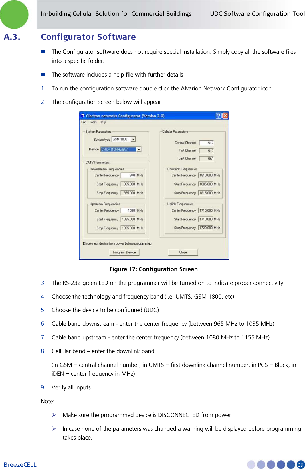
Alvarion Technologies Ltd. Dual Band Cellular Booster
UserManual.wiki
>
Alvarion Technologies
>
DASRU US User Manual
User Manual
Navigation menu
Upload a User Manual
Namespaces
Wiki Guide
HTML
PDF
Info
Views
User Manual
Discussion / Help
Navigation

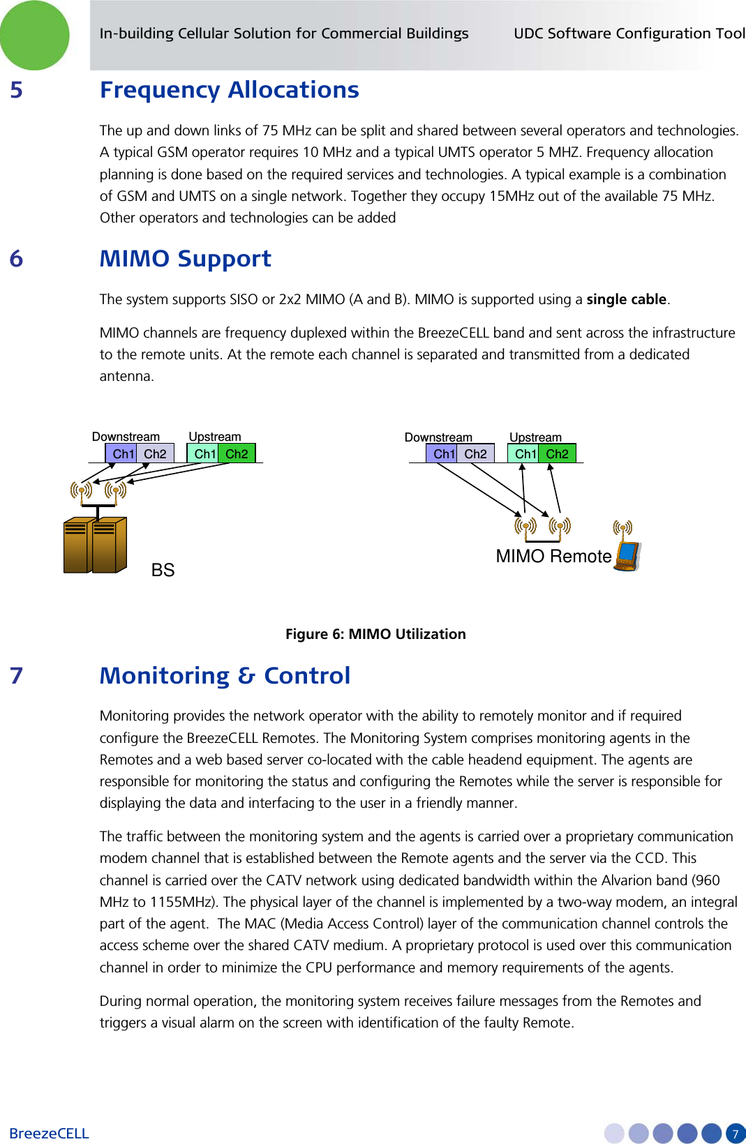
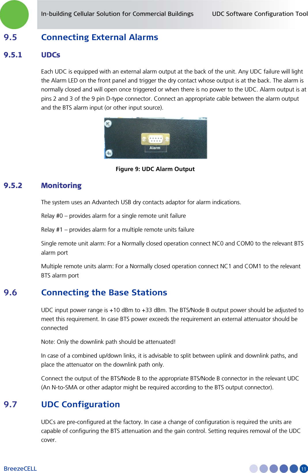
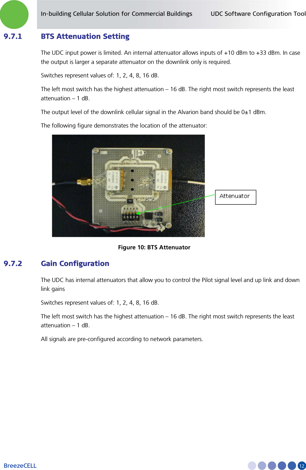
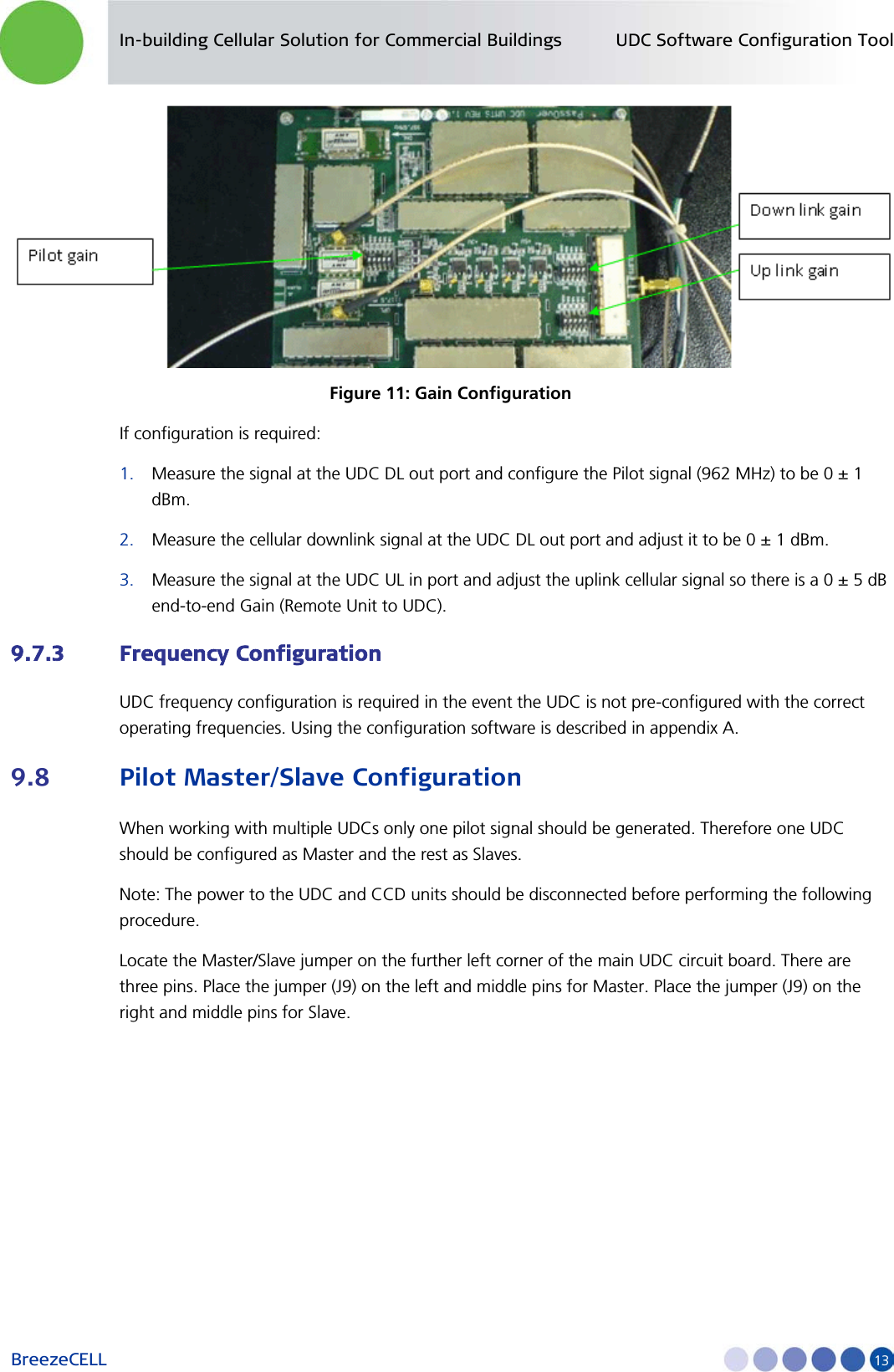
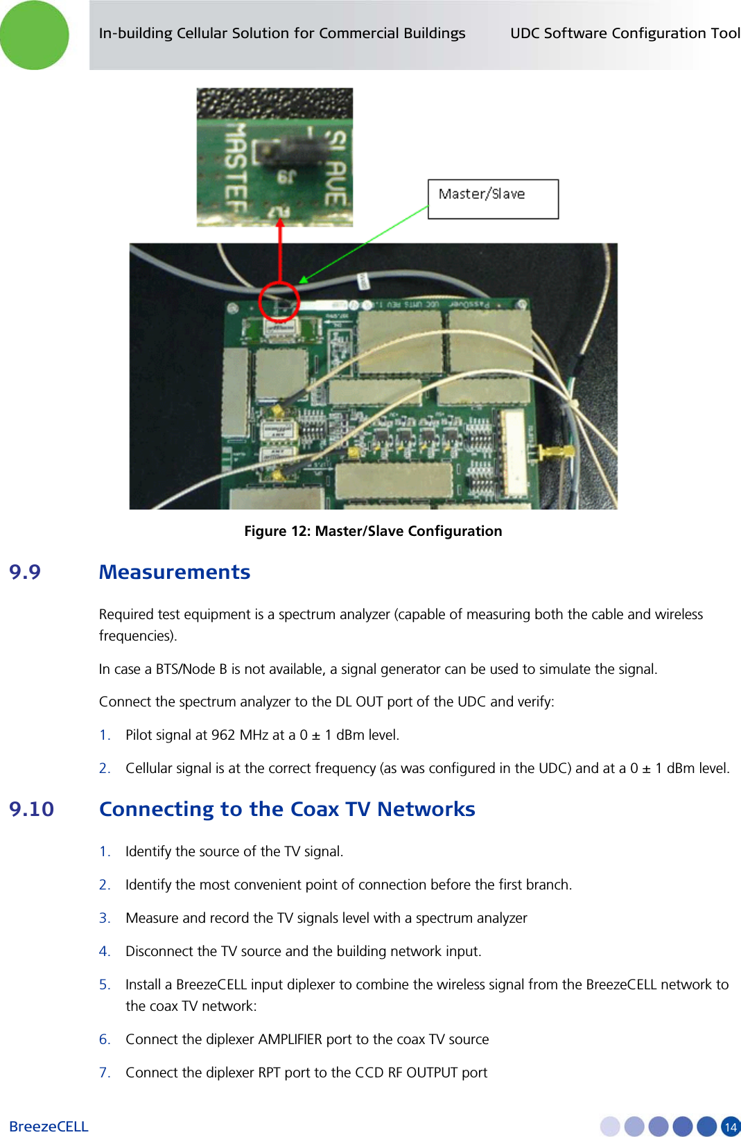
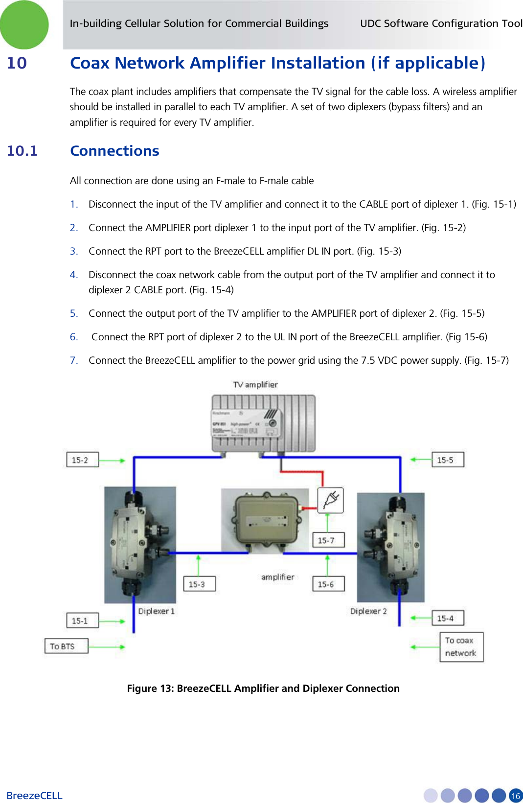
![In-building Cellular Solution for Commercial Buildings UDC Software Configuration Tool BreezeCELL 15 8. The diplexer CABLE port now carries the combined TV and wireless signal. Connect the CABLE port the to the building coax network input Note: The diplexer AC port will be in use only when the coax network is self powered by a 60 VAC source. 9.11 Measurements Use a spectrum analyzer to verify that the CABLE output of the diplexer includes the cellular, pilot and TV signals at their respective power levels as measured in sections 7.9 and 7.10. 9.12 Localized Testing Port The CCD is equipped with an ability to locally test the BTS connectivity and proper remote unit operation. The RF Output Monitoring connector in the front of the CCD is a output that is similar to the CCD RF Output with a -40 dB attenuation. A remote unit can be directly connected to this output to test the BTS output without the need to disrupt the coax plant. 9.13 Determining BTS Output Power VS. Remote Unit Output Power BreezeCELL remote units are offered with two output power settings: 0 dBm and 10 dBm. The remote unit output power setting is per carrier. The system maintains constant linear gain between the BTS and the remote unit, thus enabling the BTS/MS power control mechanism to operate normally. The BTS power output should be configured not to exceed the UDC input power specification. Example: GSM BTS with a 46 dBm output power. External downlink attenuation between BTS and UDC (Attenuation at UDC input) UDC internal attenuation set at 20 dB Remote unit output power 10 dBm (per carrier) GSM BCCH is measured at 0 dBm at the output of the UDC Number of Carriers Attenuation at UDC Input [dB] UDC Output [dBm] Remote Unit Output Power [dBm] 1 26 0 10 2 23 3 13 4 20 6 16 8 17 9 19](https://usermanual.wiki/Alvarion-Technologies/DASRU-US/User-Guide-1556394-Page-22.png)
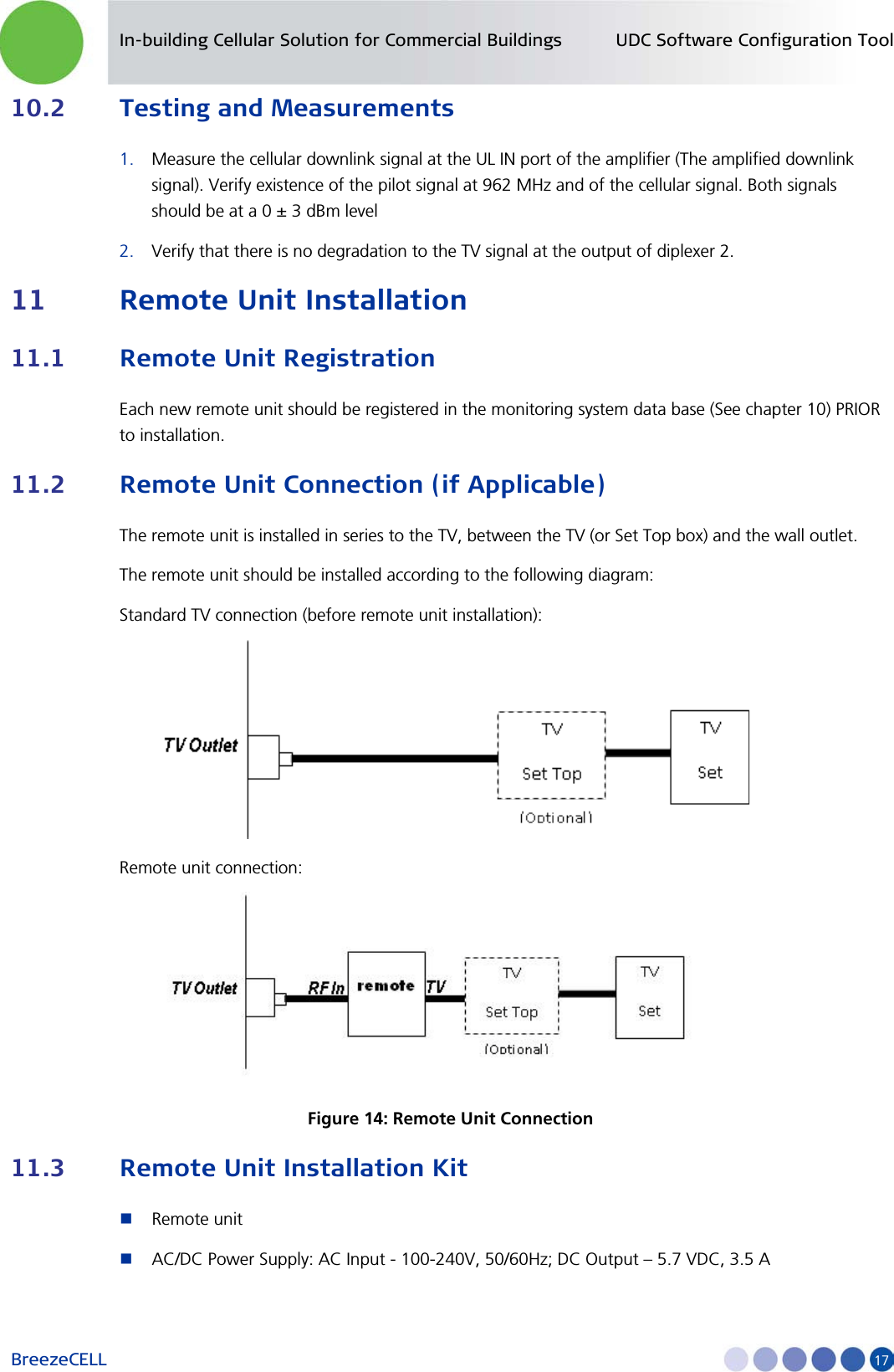
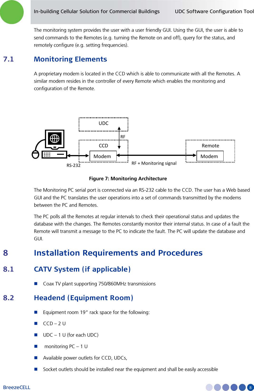
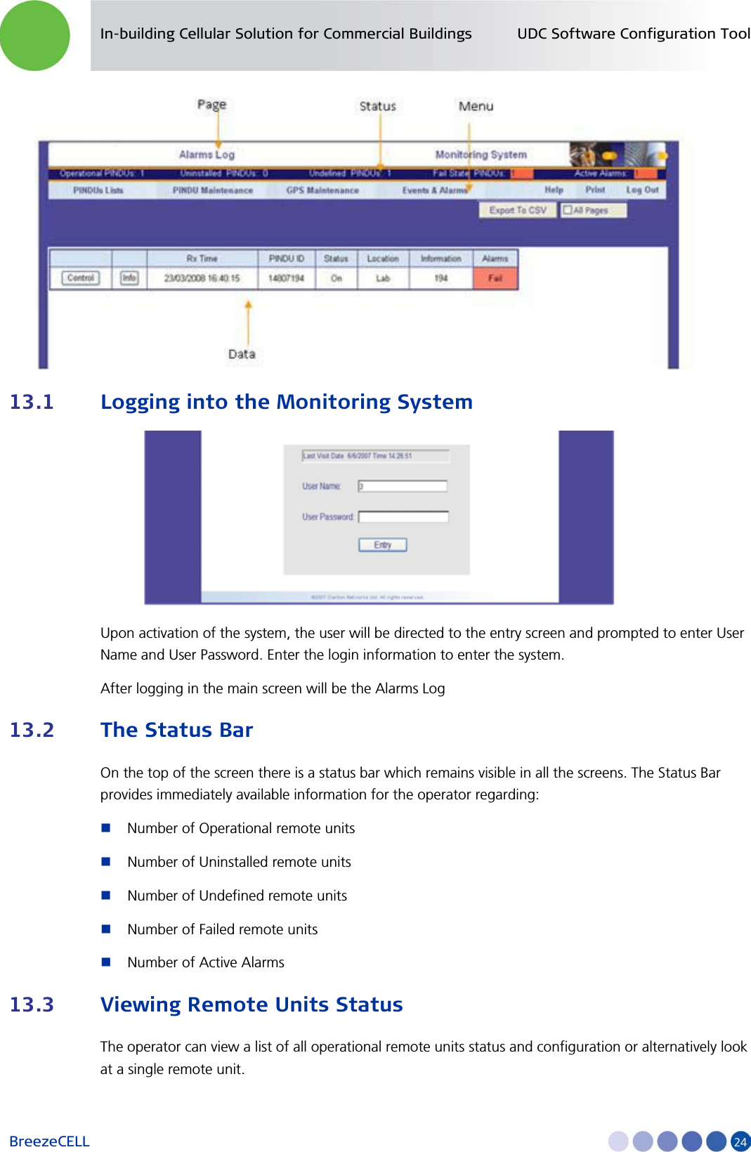
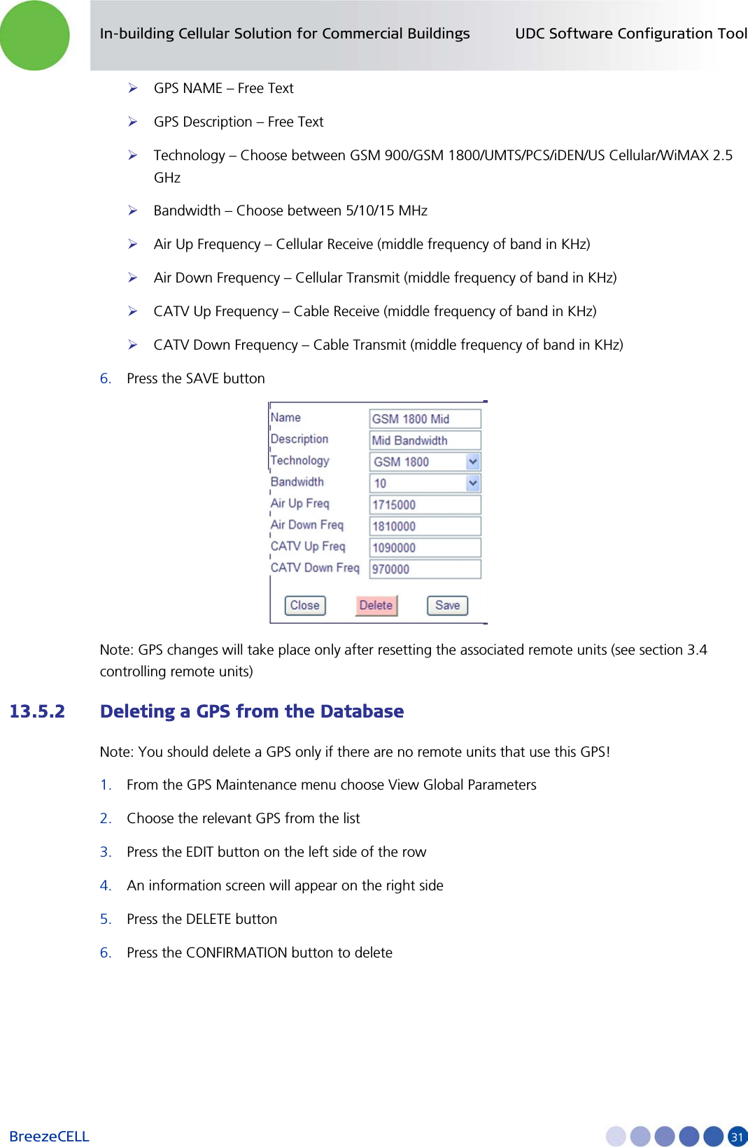
![In-building Cellular Solution for Commercial Buildings UDC Software Configuration Tool BreezeCELL 20 After logging in, the main screen will be the Alarms Log. 12.2 Configuring a Global Parameter Set (GPS) A group of remote units with the same frequency requirements should be allocated a common parameter set called GPS. Each GPS include: Cellular (Air) Up Link Frequency Cellular (Air) Down Link Frequency CATV Up Link Frequency CATV Down Link Frequency A change in the GPS will generate a change in each remote unit using this GPS. Note: You can’t edit the GPS name, as this is used by its associated remote units 12.2.1 Adding a GPS 1. From the menu GPS MAINTENANCE choose Add Group Parameters 2. Press the ADD GPS button on the top left side of the screen. The GPS configuration table will appear. 3. Enter a Name and Description of the GPS. The name should be unique. 4. Choose the technology from the list: GSM 900, GSM 1800, UMTS, PCS, iDEN, US Cellular 5. Choose the channel Bandwidth of the remote unit (factory hardware preset) 6. Fill in the Cellular and CATV frequencies according to your frequency plan so that there is a match with the channel bandwidth and the technology. The frequency units are [KHz] 7. Press Save to update the database 8. Repeat steps b to g for each GPS required in the network](https://usermanual.wiki/Alvarion-Technologies/DASRU-US/User-Guide-1556394-Page-27.png)
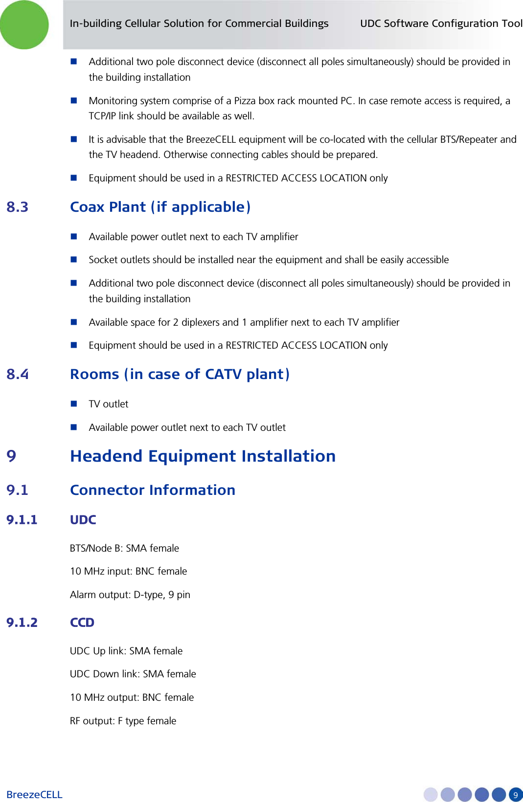
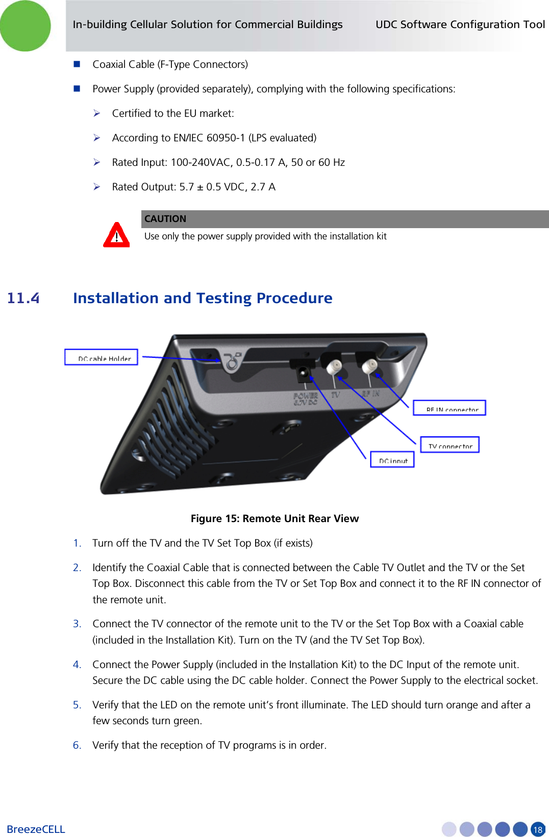
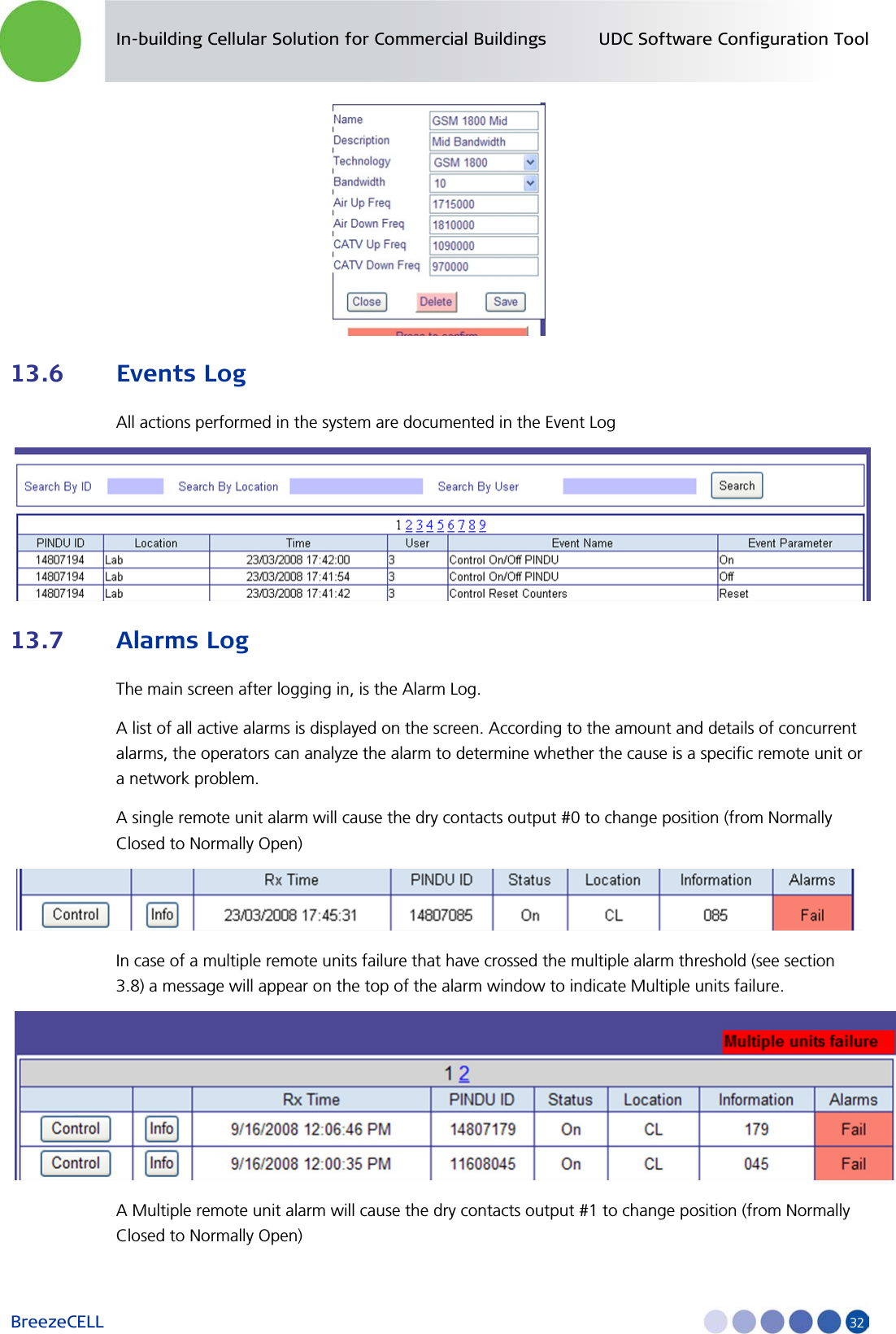
![In-building Cellular Solution for Commercial Buildings UDC Software Configuration Tool BreezeCELL 21 In the case of a dual technology remote unit, two separate GPSs are required for the remote unit to be fully operational. 12.2.2 Deleting a GPS Note: You should delete a GPS only if there are no remote units that belong to this GPS! 1. From the menu GPS MAINTENANCE choose View Group Parameters 2. Press the EDIT button of the relevant GPS 3. Press the DELETE button 4. Press the confirmation button 12.3 Adding and Registering a New Remote Unit Each remote unit installed in the network should be defined and registered prior to installation. 1. From the remote unit MAINTENANCE menu choose Edit/Add remote unit 2. Press the Add remote unit button on the top left side of the screen. The remote unit configuration table will appear. 3. Input all remote unit parameters: Remote unit ID = serial number Location [Free text] Information [Free text]](https://usermanual.wiki/Alvarion-Technologies/DASRU-US/User-Guide-1556394-Page-28.png)
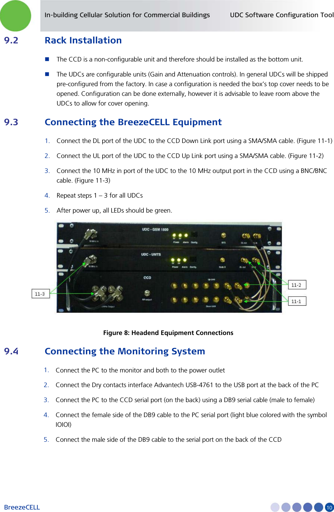
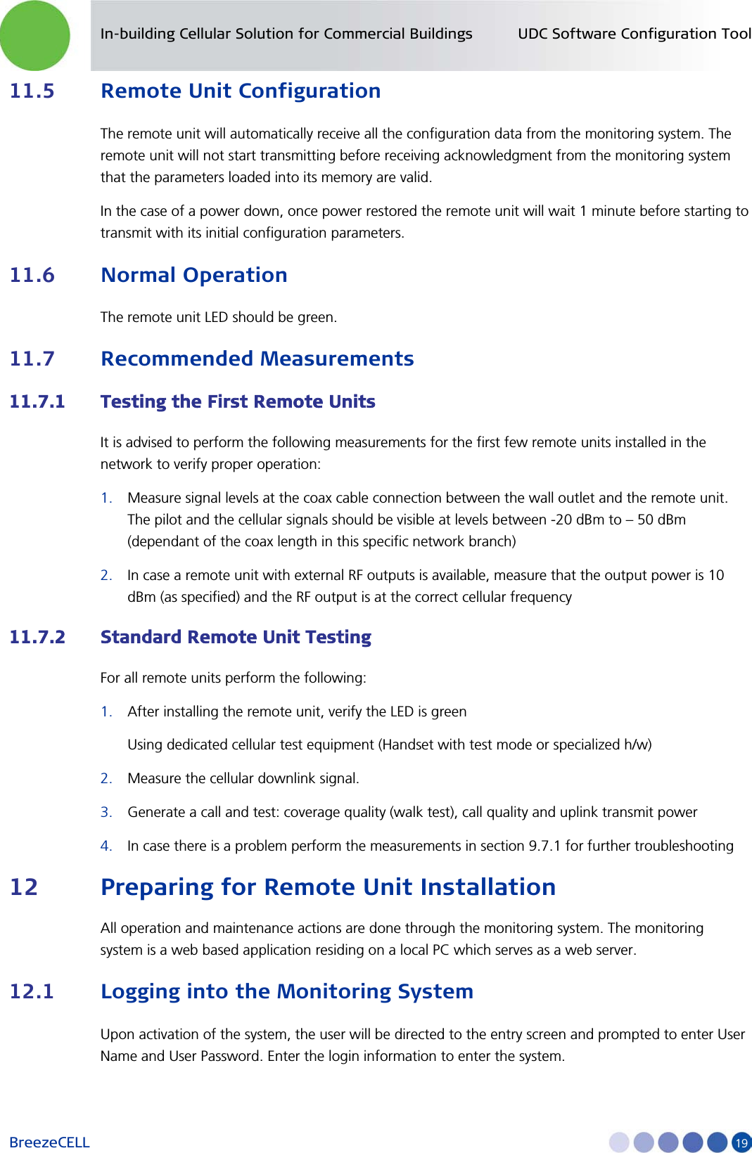
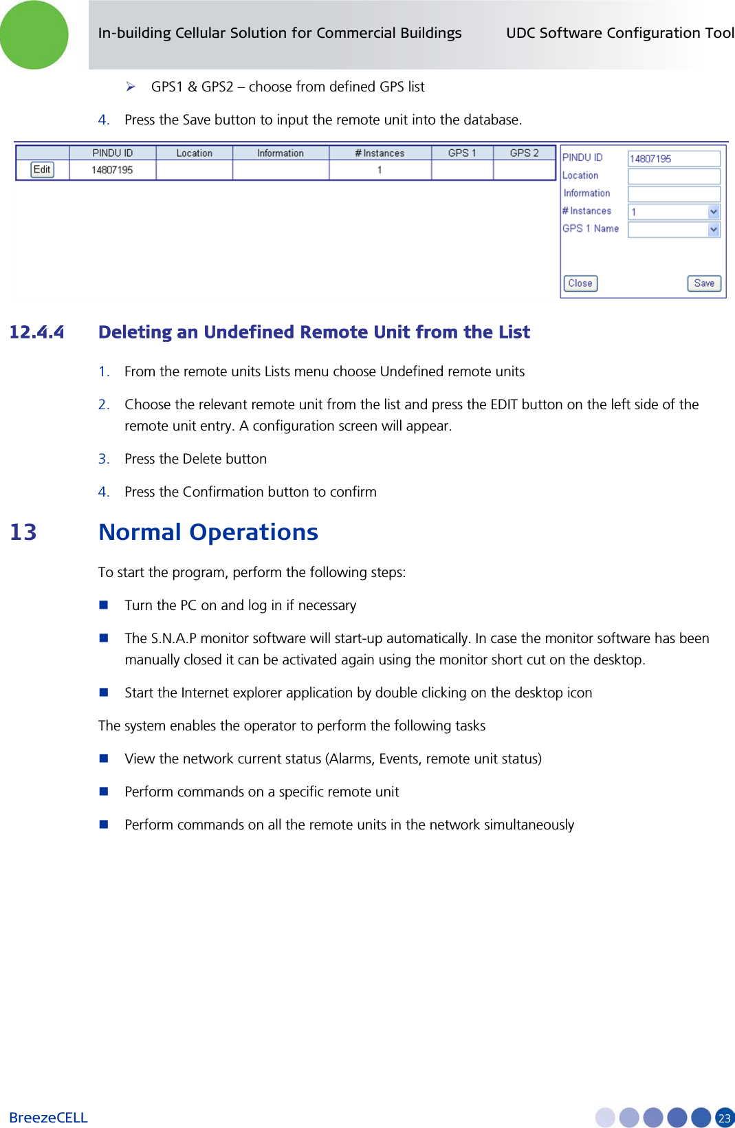
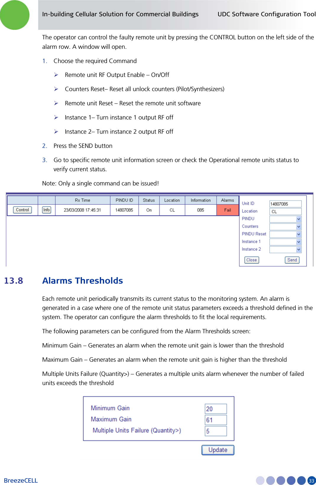
![In-building Cellular Solution for Commercial Buildings UDC Software Configuration Tool BreezeCELL 22 Number of instances - single [1] or dual technology [2] GPS1 & GPS2 – choose from defined GPS list 4. Press the Save button to input the remote unit into the database 12.4 Installing a Remote Unit Once a remote unit is installed in the field, it will communicate with the monitoring system and will receive operational configuration parameters. There are two possible scenarios: Uninstalled remote unit – a remote unit which is defined in the database Undefined remote unit – a remote unit which was not previously defined in the database 12.4.1 Uninstalled Remote Unit Adding a new remote unit into the database will generate an uninstalled remote unit entry. This refers to a remote unit that was properly defined in the system and should be installed in the field. At the moment the remote unit is physically installed, it communicates with the monitoring system, all parameters are verified and downloaded to the remote unit, after that the remote unit receives a permission to radiate. 12.4.2 Undefined Remote Unit A remote unit that was physically installed in the field, but was not entered into the database prior to installation. Such a remote unit will be transferred to the undefined remote unit s list and requires operator configuration of the relevant parameters in the monitoring system to become operational. 12.4.3 Adding an Undefined Remote Unit into the Database 1. From the remote units Lists menu choose Undefined remote units 2. Choose the relevant remote unit from the list and press the EDIT button on the left side of the remote unit entry. A configuration screen will appear. 3. Enter the remote unit information Location [Free text] Information [Free text] Number of instances - single [1] or dual technology [2]](https://usermanual.wiki/Alvarion-Technologies/DASRU-US/User-Guide-1556394-Page-29.png)
![In-building Cellular Solution for Commercial Buildings Power Ratings BreezeCELL 42 Appendix B. Power Ratings Device Input Voltage [Volts DC] Current [Amperes DC ] UDC 9 1 CCD 110/230 Volts AC (50/60Hz) 0.05 Amperes AC Amplifier 7.5 0.3 Remote unit 5.7 2.7](https://usermanual.wiki/Alvarion-Technologies/DASRU-US/User-Guide-1556394-Page-49.png)