Alvarion Technologies DASRU-US Dual Band Cellular Booster User Manual
Alvarion Technologies Ltd. Dual Band Cellular Booster
User Manual

BreezeCELL - In-building Cellular
Solution for Commercial Buildings
Installation, Operation &
Maintenance and Testing
Procedures

In-building Cellular Solution for Commercial Buildings Contents
BreezeCELL
ii
© Copyright 2011 Alvarion Ltd. All rights reserved.
The material contained herein is proprietary, privileged, and confidential and owned by Alvarion or its third
party licensors. No disclosure thereof shall be made to third parties without the express written permission
of Alvarion Ltd.
Alvarion Ltd. reserves the right to alter the equipment specifications and descriptions in this publication
without prior notice. No part of this publication shall be deemed to be part of any contract or warranty
unless specifically incorporated by reference into such contract or warranty.
Alvarion®, BreezeCOM®, WALKair®, WALKnet®, BreezeNET®, BreezeACCESS®, BreezeMAX®,
BreezeLITE®, 4Motion®, and/or other products and/or services referenced herein are either registered
trademarks, trademarks or service marks of Alvarion Ltd.
All other names are or may be the trademarks of their respective owners.
“WiMAX Forum” is a registered trademark of the WiMAX Forum. “WiMAX,” the WiMAX Forum logo,
“WiMAX Forum Certified,” and the WiMAX Forum Certified logo are trademarks of the WiMAX Forum.
Limitation of Liability:
(a) Alvarion shall not be liable to the purchaser or to any third party, for any loss of profits, loss of use,
interruption of business or for any indirect, special, incidental, punitive or consequential damages of any
kind, whether arising under breach of contract, tort (including negligence), strict liability or otherwise and
whether based on this agreement or otherwise, even if advised of the possibility of such damages.
(b) To the extent permitted by applicable law, in no event shall the liability for damages hereunder of
Alvarion or its employees or agents exceed the purchase price paid for the product by purchaser, nor shall
the aggregate liability for damages to all parties regarding any product exceed the purchase price paid for
that product by that party (except in the case of a breach of a party’s confidentiality obligations).

In-building Cellular Solution for Commercial Buildings Contents
BreezeCELL
iii
Contents
1 Introduction ...................................................................................................... 1
2 The Concept ...................................................................................................... 1
3 BreezeCELL Architecture .................................................................................. 2
3.1 Typical Network .................................................................................................................... 2
3.2 Existing Cable TV Network .................................................................................................. 2
3.2.1 Frequency Limitations ....................................................................................................... 3
3.2.2 BreezeCELL Solution ......................................................................................................... 3
4 BreezeCELL Network Elements ........................................................................ 4
4.1 BreezeCELL Head End Equipment ....................................................................................... 4
4.1.1 UDC – Up Down Converter .............................................................................................. 4
4.1.2 CCD – Coax Cable Distribution ........................................................................................ 5
4.1.3 Monitoring & Control ....................................................................................................... 5
4.2 Optical Network Equipment ................................................................................................ 5
4.2.1 OCD – Optical Cable Distribution ..................................................................................... 5
4.2.2 OCN – Optical Cable Node ............................................................................................... 5
4.3 Coaxial Network Equipment ................................................................................................ 5
4.3.1 Bypass Filter - Diplexer ...................................................................................................... 6
4.3.2 Bi-directional Amplifier ..................................................................................................... 6
4.4 Remote Unit .......................................................................................................................... 6

In-building Cellular Solution for Commercial Buildings Contents
BreezeCELL
iv
5 Frequency Allocations ...................................................................................... 7
6 MIMO Support .................................................................................................. 7
7 Monitoring & Control ....................................................................................... 7
7.1 Monitoring Elements ............................................................................................................ 8
8 Installation Requirements and Procedures ..................................................... 8
8.1 CATV System (if applicable) ................................................................................................. 8
8.2 Headend (Equipment Room) ............................................................................................... 8
8.3 Coax Plant (if applicable) ..................................................................................................... 9
8.4 Rooms (in case of CATV plant) ............................................................................................ 9
9 Headend Equipment Installation ..................................................................... 9
9.1 Connector Information ......................................................................................................... 9
9.1.1 UDC ................................................................................................................................. 9
9.1.2 CCD ................................................................................................................................. 9
9.2 Rack Installation ................................................................................................................. 10
9.3 Connecting the BreezeCELL Equipment ............................................................................ 10
9.4 Connecting the Monitoring System .................................................................................. 10
9.5 Connecting External Alarms .............................................................................................. 11
9.5.1 UDCs .............................................................................................................................. 11
9.5.2 Monitoring ..................................................................................................................... 11
9.6 Connecting the Base Stations ............................................................................................ 11
9.7 UDC Configuration ............................................................................................................. 11
9.7.1 BTS Attenuation Setting ................................................................................................. 12
9.7.2 Gain Configuration ........................................................................................................ 12
9.7.3 Frequency Configuration ................................................................................................ 13
9.8 Pilot Master/Slave Configuration ...................................................................................... 13

In-building Cellular Solution for Commercial Buildings Contents
BreezeCELL
v
9.9 Measurements .................................................................................................................... 14
9.10 Connecting to the Coax TV Networks ........................................................................... 14
9.11 Measurements ................................................................................................................. 15
9.12 Localized Testing Port ..................................................................................................... 15
9.13 Determining BTS Output Power VS. Remote Unit Output Power .............................. 15
10 Coax Network Amplifier Installation (if applicable) ..................................16
10.1 Connections ..................................................................................................................... 16
10.2 Testing and Measurements ............................................................................................ 17
11 Remote Unit Installation ..............................................................................17
11.1 Remote Unit Registration ............................................................................................... 17
11.2 Remote Unit Connection (if Applicable) ....................................................................... 17
11.3 Remote Unit Installation Kit ........................................................................................... 17
11.4 Installation and Testing Procedure ................................................................................ 18
11.5 Remote Unit Configuration ............................................................................................ 19
11.6 Normal Operation ........................................................................................................... 19
11.7 Recommended Measurements....................................................................................... 19
11.7.1 Testing the First Remote Units ........................................................................................ 19
11.7.2 Standard Remote Unit Testing ........................................................................................ 19
12 Preparing for Remote Unit Installation .......................................................19
12.1 Logging into the Monitoring System ............................................................................ 19
12.2 Configuring a Global Parameter Set (GPS) ................................................................... 20
12.2.1 Adding a GPS ................................................................................................................. 20
12.2.2 Deleting a GPS ............................................................................................................... 21
12.3 Adding and Registering a New Remote Unit ............................................................... 21
12.4 Installing a Remote Unit ................................................................................................. 22

In-building Cellular Solution for Commercial Buildings Contents
BreezeCELL
vi
12.4.1 Uninstalled Remote Unit ................................................................................................. 22
12.4.2 Undefined Remote Unit .................................................................................................. 22
12.4.3 Adding an Undefined Remote Unit into the Database .................................................... 22
12.4.4 Deleting an Undefined Remote Unit from the List ........................................................... 23
13 Normal Operations .......................................................................................23
13.1 Logging into the Monitoring System ............................................................................ 24
13.2 The Status Bar ................................................................................................................. 24
13.3 Viewing Remote Units Status ........................................................................................ 24
13.3.1 Viewing the Operational Remote Units Status ................................................................ 25
13.3.2 Viewing the Operational Remote Units Configuration .................................................... 25
13.3.3 Viewing the Complete Information of a Single Remote Unit ........................................... 26
13.4 Controlling Remote Units ............................................................................................... 28
13.4.1 Controlling a Single Remote Unit ................................................................................... 28
13.4.2 Issuing a Global Command ............................................................................................. 28
13.4.3 Editing Remote Unit Configuration ................................................................................. 29
13.4.4 Deleting a Remote Unit from the Database .................................................................... 30
13.5 GPS Maintenance ............................................................................................................ 30
13.5.1 Editing a GPS ................................................................................................................. 30
13.5.2 Deleting a GPS from the Database ................................................................................. 31
13.6 Events Log ....................................................................................................................... 32
13.7 Alarms Log ....................................................................................................................... 32
13.8 Alarms Thresholds .......................................................................................................... 33
13.9 Exporting the Database .................................................................................................. 34
13.10 Database Backup ............................................................................................................. 34
14 Acceptance Testing ......................................................................................35

In-building Cellular Solution for Commercial Buildings Contents
BreezeCELL
vii
14.1 Headend Equipment Testing.......................................................................................... 35
14.1.1 BTS Output Measurement .............................................................................................. 35
14.1.2 UDC Testing ................................................................................................................... 35
14.2 Coax Network Amplifier Testing ................................................................................... 36
14.2.1 Amplifier Downlink Signal Measurement ........................................................................ 36
14.3 Remote Unit Testing ....................................................................................................... 36
14.3.1 Remote Unit LEDs ........................................................................................................... 36
14.4 Remote Unit Measurements .......................................................................................... 36
14.4.1 Testing the First Remote Units ........................................................................................ 36
14.4.2 Standard Remote Unit Testing ........................................................................................ 36
14.4.3 Global Walk Test ............................................................................................................ 37
Appendix A. UDC Software Configuration Tool ...............................................38
A.1. Requirements ...................................................................................................................... 38
A.2. Connecting the Programmer ............................................................................................. 38
A.3. Configurator Software ....................................................................................................... 39
A.4. Tools .................................................................................................................................... 40
A.4.1. Recall Configuration from a Device ................................................................................ 40
A.4.2. Use Device Configuration ............................................................................................... 40
A.5. Configuration Management .............................................................................................. 40
A.5.1. Saving a Configuration ................................................................................................... 41
A.5.2. Loading a Configuration ................................................................................................. 41
A.5.3. Deleting a Configuration ................................................................................................ 41
Appendix B. Power Ratings ................................................................................42

In-building Cellular Solution for Commercial Buildings UDC Software Configuration Tool
BreezeCELL 1
1 Introduction
Indoor wireless coverage is one of the most challenging areas in the wireless industry. Alvarion develops
innovative communications equipment, infrastructure and products – enabling wireless operators and
property owners to deliver high quality indoor wireless services using a Distributed Antenna System
(DAS).
Alvarion developed a unique DAS solution for improving in-building wireless coverage in commercial
buildings such as airports, stadiums, shopping malls, hotels, office buildings and residential areas. Such
locations suffer from wireless coverage problems such as interference, attenuation, and multi-path due
to their height and build. The solution is installed using a hybrid fiber and TV type coaxial cables.
BreezeCELL’s unique flat architecture makes it extremely cost effective.
The solution can also be installed using existing coax cables infrastructure, used to distribute TV signals
within the building. Alvarion believes that utilizing the already installed TV infrastructure is the most
cost effective means of providing these services.
Value proposition
Affordable active Distributed Antenna System
Very low installation cost
Unique MIMO on a single cable solution
Plug and Play - very fast and flexible installation process
Multi-Operator, Multi service
Easy design and fine tuning
Fast ROI
2 The Concept
Indoor wireless coverage is traditionally done via external macro cells. In many cases coverage is
problematic due to interference, attenuation, multi-path and other issues.
BreezeCELL distributes the cellular signal throughout the property over a combination of fiber and 75
ohm coax to active remote units and antennas located throughout the building area.
On the other hand, almost all buildings are equipped with coax cables infrastructure, used to distribute
TV signals within the building. Alvarion's solution can use this existing cabling infrastructure through
unutilized bandwidth on the coax cables to bring wireless services into the indoors environment.
Alvarion's technology enables servicing multiple operators and technologies (i.e GSM, UMTS, CDMA,
WiMAX, iDEN) over the same infrastructure in order to increase the utilization of the cable
infrastructure. BreezeCELL is a forward compatible system and fits current and future protocols (LTE,
etc) and has a unique MIMO solution on a single cable support.
In-building Cellular Solution for Commercial Buildings UDC Software Configuration Tool
BreezeCELL 2
3 BreezeCELL Architecture
3.1 Typical Network
A wireless signal source (BTS/Node B/, Micro, Pico, Femto, Repeater) is installed in a central point in the
building. Cabling infrastructure (fiber and coax) is installed according to a pre-designed RF coverage
plan.
The wireless signal is shifted in frequency to the Alvarion intermediate band and then combined in the
RF level. The combined RF signal is then converted to an optical signal which is being transmitted via
the fiber link. At the coverage area the optical signal is being converted back to RF and propagated
along the coaxial network down to the remote units. If required and in order to overcome the coax
cable attenuation, a wire amplifier is used to boost the signal. Remote units are connected to the cable
and transmit via a built-in antenna (or an external antenna) the wireless signals indoors at their original
licensed frequency.
In the case of TDD transmissions such as WiMAX and LTE, the BreezeCELL equipment converts the TDD
signal to FDD at both ends of the system (Headend and Remote). TDD synchronization is run over the
system.
It is important to note that there is no modification to the original signal generated by the Wireless
equipment. BreezeCELL is an active DAS, carrying the signal to the remote small antenna (Remote unit)
where it radiates in its original form.
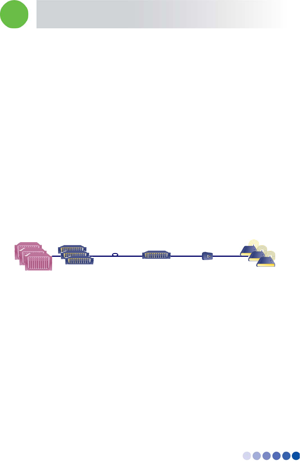
The following diagram illustrates the BreezeCELL network:
Figure 1: BreezeCELL Architecture
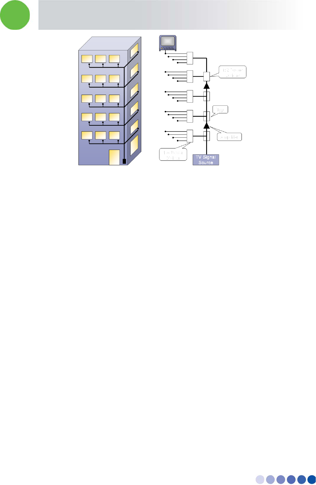
3.2 Existing Cable TV Network
A typical in building TV coax network is built as a tree and branch architecture. TV signals are delivered
from a common source (which can be a terrestrial antenna, CATV or satellite dish/receiver) to TV outlets
within the building. In order to compensate for losses in the coaxial cables a set of amplifiers are
installed at various locations throughout the network to increase the signal gain. The signal is
distributed to branches using taps and to the outlets using power dividers. Amplifiers can also be found
in the branches.
BTS/Node B
UDC/OCD
(RF <> Optic)
OCN
(Optic <> RF)
Amplifier
(optional)
Remote Units
Fiber
Coax
In-building Cellular Solution for Commercial Buildings UDC Software Configuration Tool
BreezeCELL 3
Figure 2: Typical Cable Network
3.2.1 Frequency Limitations
In order to pass through frequencies of 960 to 1155 MHz we need to examine the frequency
limitations of the coax network elements. The only limiting element in the coax network is the amplifier
used to boost the signal which is bypassed by the DAS system. All other elements namely coax cables,
connectors, taps, power dividers and outlets are capable of handling the required frequencies.
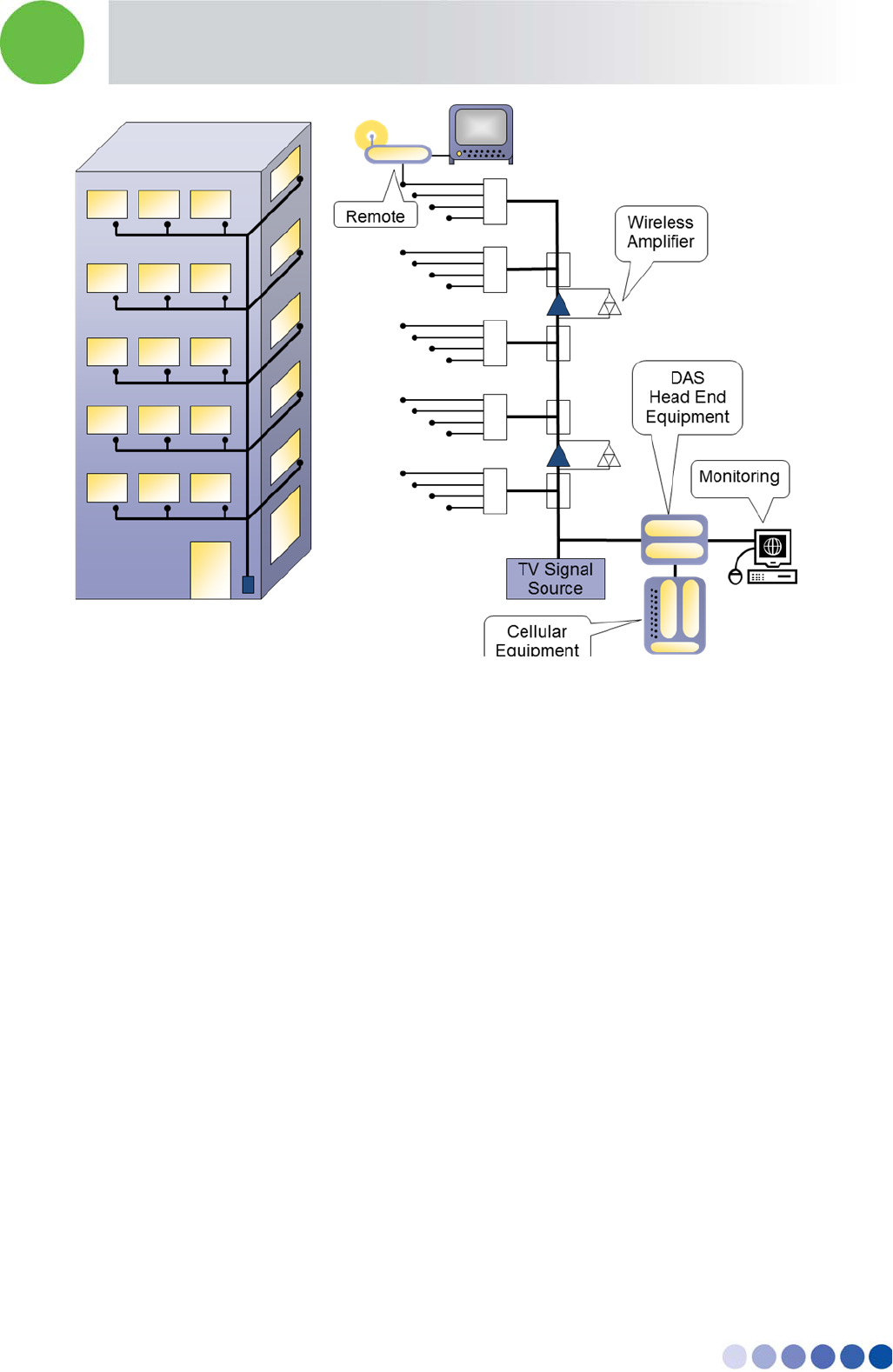
3.2.2 BreezeCELL Solution
Wireless equipment is installed at the entry point of the TV signals to the building. The TV signals entry
point may be a terrestrial antenna, a satellite dish or CATV feed. In some cases, like hotels, the source
of the TV signals may be a stack of CATV or satellite receivers and a VOD/PPV system. The wireless
equipment may be a microcell, a picocell or a wireless repeater.
The wireless signal is shifted in frequency to the Alvarion band and then combined with the TV signals.
Since the Alvarion band is above the TV signal band, there is no interference between the two signals.
The combined signal is propagated along the coaxial network down to the TV outlets. In order to
overcome the frequency limitation of the cable amplifier a bypass circuit is used to separate the wireless
signal, amplify it and then recombine the frequencies. At the end user’s TV outlet a small CPE called
Remote is connected which transmits the wireless signals indoors at their original licensed frequency.
In the case of TDD transmissions such as WiMAX, the BreezeCELL equipment converts the TDD signal
to FDD at both ends of the system (Headend and Remote). TDD synchronization is run over the system.
It is important to note that there is no modification to the original signal generated by the Wireless
equipment. BreezeCELL is an active DAS, carrying the signal to the remote small antenna (Remote)
where it radiates in its original form.
The following diagram illustrates the BreezeCELL network overlaying the cable TV infrastructure:
In-building Cellular Solution for Commercial Buildings UDC Software Configuration Tool
BreezeCELL 4
Figure 3: BreezeCELL Architecture
4 BreezeCELL Network Elements
The BreezeCELL network is composed of three parts: BreezeCELL Head end equipment, Coaxial
Network equipment and Customer Premises (or end user) Equipment.
4.1 BreezeCELL Head End Equipment
The BreezeCELL head end equipment is co-located with the TV signal source of the building. The
purpose of BreezeCELL’s Head end equipment is aggregating wireless services signals, converting them
into the correct frequency range and combining them on the coaxial network. Remote monitoring and
control of the Remotes is performed using the monitoring system in the headend. The wireless
equipment (microcell or repeater) is also installed at the same location.
4.1.1 UDC – Up Down Converter
The wireless native RF signal is inserted into Alvarion Up/Down Converter (UDC). The UDC converts the
original wireless signal into the 960 – 1155 range. In TDD networks (WiMAX) the UDC also converts
TDD signals to FDD. The output of several UDCs can be aggregated together by the CCD (see 4.1.2
below) in order to combine several operators and technologies or aggregate traffic.
In-building Cellular Solution for Commercial Buildings UDC Software Configuration Tool
BreezeCELL 5
4.1.2 CCD – Coax Cable Distribution
The CCD combines the RF inputs and outputs of several UDCs into a single coaxial connection. The
CCD also provides a reference clock for all UDCs by supplying them an accurate 10 MHz clock signal.
Through the CCD the system monitoring signals are sent to the network elements. A single CCD can
support up-to 8 UDCs.
960÷1155
MHz
CCD Coaxial Cable
(Up and Down)
UDC
10 MHz
Cell
Microcell or
Repeater
Native
RF
Figure 4: Head End Equipment
4.1.3 Monitoring & Control
A communication link exists between the Monitoring software residing on a PC at the headend and the
remotes. The monitoring & control systems enables the user to remotely configure the Remotes
operating frequencies, turn a Remote on/off and monitor various Remote parameters. Alarms
generated at the Remotes will be communicated to Monitoring and be displayed for the user.
4.2 Optical Network Equipment
4.2.1 OCD – Optical Cable Distribution
The OCD has the same functionality of the CCD. OCD combines the RF inputs and outputs of several
UDCs into a single fiber connection.
4.2.2 OCN – Optical Cable Node
A fiber is pulled in between the BTS location and the main coverage area, where coax is being laid. The
optical signal is converted to RF signal using the OCN which is an RF optic transceiver.
4.3 Coaxial Network Equipment
The purpose of the bypass infrastructure is enabling the transfer of the 960 -1155 MHZ frequency band
over the standard cable TV Coax amplifiers. The cable TV amplifiers are the only element in the network
which does not handle this frequency range and therefore the higher frequency signal should bypass
those amplifiers and be amplified separately. The amplifiers are bi-directional and carry both the
forward and return wireless signals.
In-building Cellular Solution for Commercial Buildings UDC Software Configuration Tool
BreezeCELL 6
BreezeCELL’s coaxial bypass has very low power consumption and can be fed from the electrical grid or
from AC voltage sent over the coax plant.
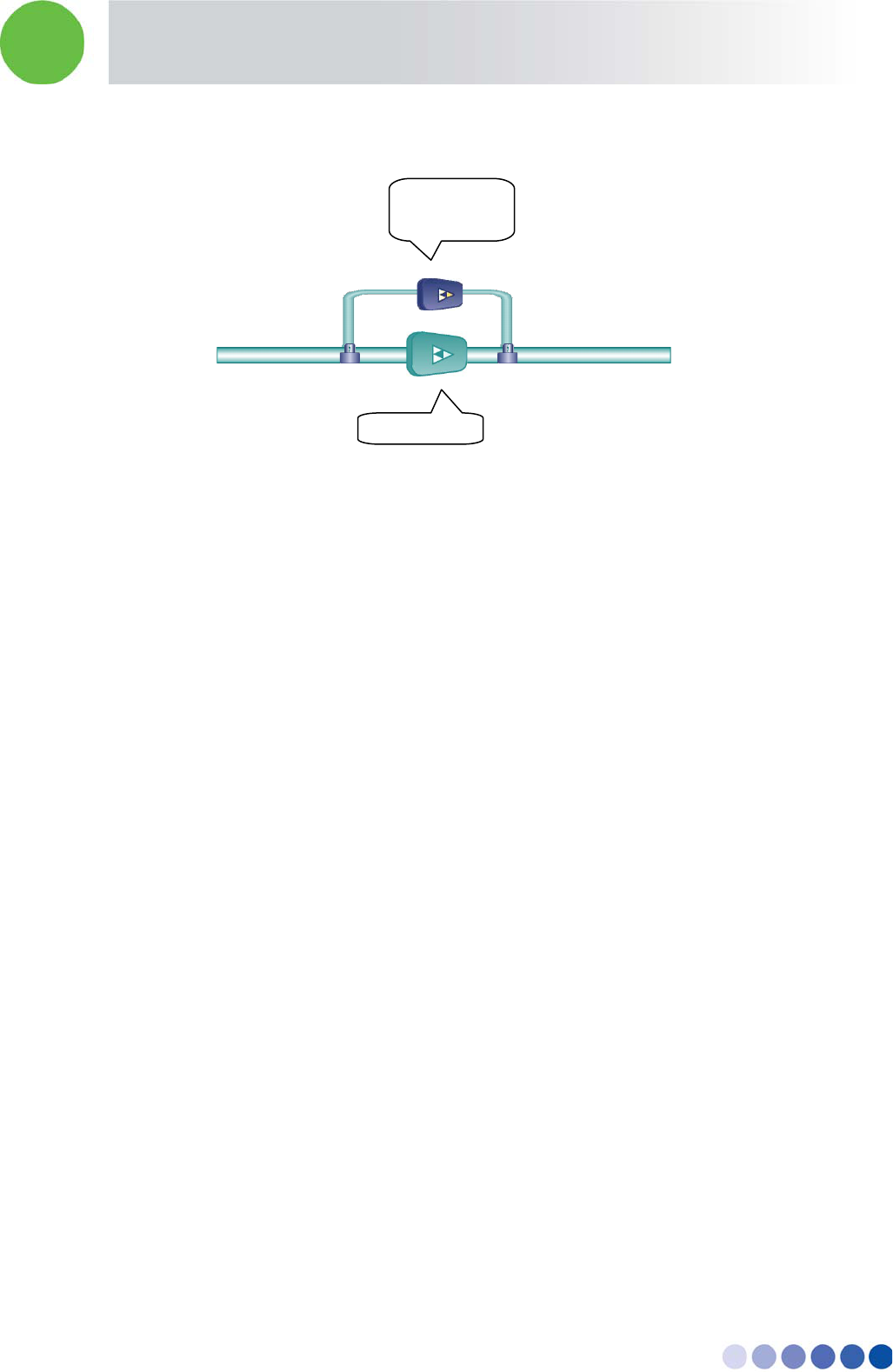
Figure 5: Bypass Infrastructure
4.3.1 Bypass Filter - Diplexer
The Bypass filter is a passive element that separates the lower frequency cable TV signals 5-860 MHz
and the higher Alvarion's frequencies of 960- 1155 MHz. The design of the bypass filter is based on a
diplexer which passes the standard cable TV signals with low attenuation and provides the required
separation between them and the Alvarion signals. For self powering systems the diplexer also samples
the AC signal that runs on the coax and uses it to power the Alvarion amplifier. A bypass filter is used
for splitting the signals before amplification and for combining the wireless and cable signals after
amplification.
4.3.2 Bi-directional Amplifier
This element compensates for the wireless signal losses that result from coax cable attenuation. The
amplifier is a low power amplifier in order to draw minimal current from the cable network.
4.4 Remote Unit
The Remote is an active unit. The purpose of the Remote is to take the RF signals that are propagated
via the cables, convert it to the native wireless frequency and transmit it in the air inside the building.
The Remote contains a miniature UDC for frequency conversion, a transmitter and an internal antenna
(external antenna connection is available as well). The Remote receives power through the cable and
can be installed as a self contained unit.
The Remote units can be single or dual band
The Remote can operate in MIMO configuration for 4G networks.
Bypass
Bypass
Alvarion’s
Amplifier
TV Amplifier
In-building Cellular Solution for Commercial Buildings UDC Software Configuration Tool
BreezeCELL 7
5 Frequency Allocations
The up and down links of 75 MHz can be split and shared between several operators and technologies.
A typical GSM operator requires 10 MHz and a typical UMTS operator 5 MHZ. Frequency allocation
planning is done based on the required services and technologies. A typical example is a combination
of GSM and UMTS on a single network. Together they occupy 15MHz out of the available 75 MHz.
Other operators and technologies can be added
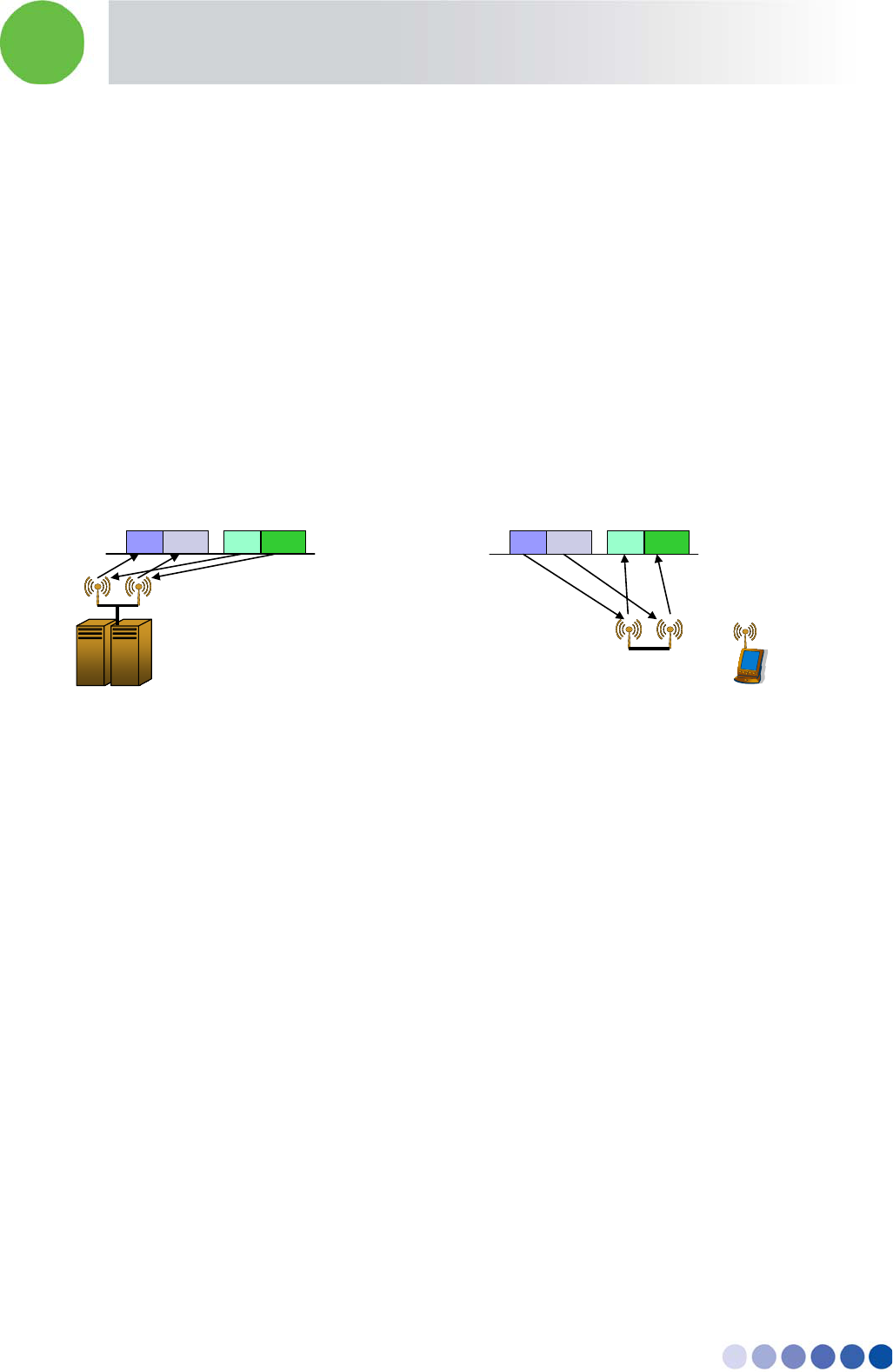
6 MIMO Support
The system supports SISO or 2x2 MIMO (A and B). MIMO is supported using a single cable.
MIMO channels are frequency duplexed within the BreezeCELL band and sent across the infrastructure
to the remote units. At the remote each channel is separated and transmitted from a dedicated
antenna.
Figure 6: MIMO Utilization
7 Monitoring & Control
Monitoring provides the network operator with the ability to remotely monitor and if required
configure the BreezeCELL Remotes. The Monitoring System comprises monitoring agents in the
Remotes and a web based server co-located with the cable headend equipment. The agents are
responsible for monitoring the status and configuring the Remotes while the server is responsible for
displaying the data and interfacing to the user in a friendly manner.
The traffic between the monitoring system and the agents is carried over a proprietary communication
modem channel that is established between the Remote agents and the server via the CCD. This
channel is carried over the CATV network using dedicated bandwidth within the Alvarion band (960
MHz to 1155MHz). The physical layer of the channel is implemented by a two-way modem, an integral
part of the agent. The MAC (Media Access Control) layer of the communication channel controls the
access scheme over the shared CATV medium. A proprietary protocol is used over this communication
channel in order to minimize the CPU performance and memory requirements of the agents.
During normal operation, the monitoring system receives failure messages from the Remotes and
triggers a visual alarm on the screen with identification of the faulty Remote.
BS
MIMO Remote
Ch1
Ch2
Downstream
Ch1
Ch2
Upstream
Ch1
Ch2
Downstream
Ch1
Ch2
Upstream
In-building Cellular Solution for Commercial Buildings UDC Software Configuration Tool
BreezeCELL 8
The monitoring system provides the user with a user friendly GUI. Using the GUI, the user is able to
send commands to the Remotes (e.g. turning the Remote on and off), query for the status, and
remotely configure (e.g. setting frequencies).
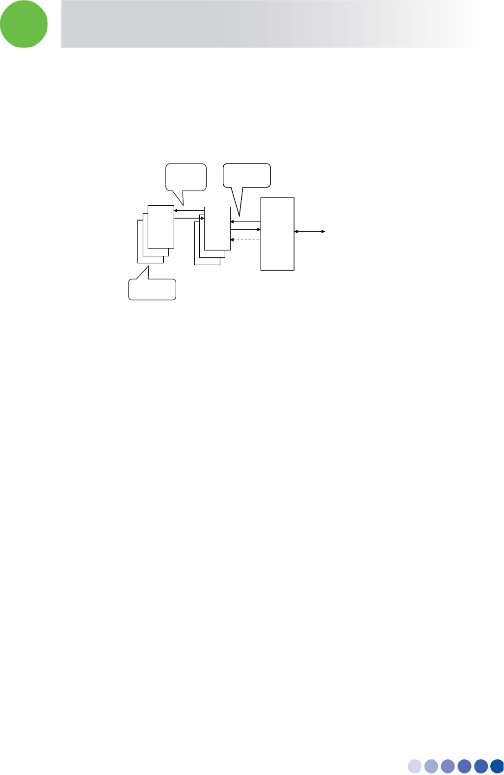
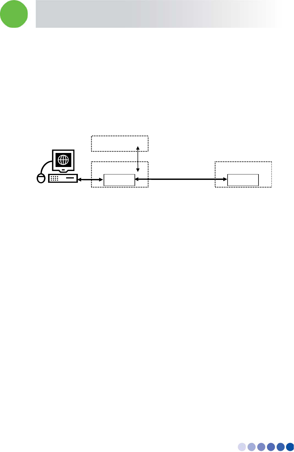
7.1 Monitoring Elements
A proprietary modem is located in the CCD which is able to communicate with all the Remotes. A
similar modem resides in the controller of every Remote which enables the monitoring and
configuration of the Remote.
Figure 7: Monitoring Architecture
The Monitoring PC serial port is connected via an RS-232 cable to the CCD. The user has a Web based
GUI and the PC translates the user operations into a set of commands transmitted by the modems
between the PC and Remotes.
The PC polls all the Remotes at regular intervals to check their operational status and updates the
database with the changes. The Remotes constantly monitor their internal status. In case of a fault the
Remote will transmit a message to the PC to indicate the fault. The PC will update the database and
GUI.
8 Installation Requirements and Procedures
8.1 CATV System (if applicable)
Coax TV plant supporting 750/860MHz transmissions
8.2 Headend (Equipment Room)
Equipment room 19” rack space for the following:
CCD – 2 U
UDC – 1 U (for each UDC)
monitoring PC – 1 U
Available power outlets for CCD, UDCs,
Socket outlets should be installed near the equipment and shall be easily accessible
CCD
Modem
RS-232
UDC
Remote
Modem
RF + Monitoring signal
RF

In-building Cellular Solution for Commercial Buildings UDC Software Configuration Tool
BreezeCELL 9
Additional two pole disconnect device (disconnect all poles simultaneously) should be provided in
the building installation
Monitoring system comprise of a Pizza box rack mounted PC. In case remote access is required, a
TCP/IP link should be available as well.
It is advisable that the BreezeCELL equipment will be co-located with the cellular BTS/Repeater and
the TV headend. Otherwise connecting cables should be prepared.
Equipment should be used in a RESTRICTED ACCESS LOCATION only
8.3 Coax Plant (if applicable)
Available power outlet next to each TV amplifier
Socket outlets should be installed near the equipment and shall be easily accessible
Additional two pole disconnect device (disconnect all poles simultaneously) should be provided in
the building installation
Available space for 2 diplexers and 1 amplifier next to each TV amplifier
Equipment should be used in a RESTRICTED ACCESS LOCATION only
8.4 Rooms (in case of CATV plant)
TV outlet
Available power outlet next to each TV outlet
9 Headend Equipment Installation
9.1 Connector Information
9.1.1 UDC
BTS/Node B: SMA female
10 MHz input: BNC female
Alarm output: D-type, 9 pin
9.1.2 CCD
UDC Up link: SMA female
UDC Down link: SMA female
10 MHz output: BNC female
RF output: F type female
In-building Cellular Solution for Commercial Buildings UDC Software Configuration Tool
BreezeCELL 10
9.2 Rack Installation
The CCD is a non-configurable unit and therefore should be installed as the bottom unit.
The UDCs are configurable units (Gain and Attenuation controls). In general UDCs will be shipped
pre-configured from the factory. In case a configuration is needed the box’s top cover needs to be
opened. Configuration can be done externally, however it is advisable to leave room above the
UDCs to allow for cover opening.
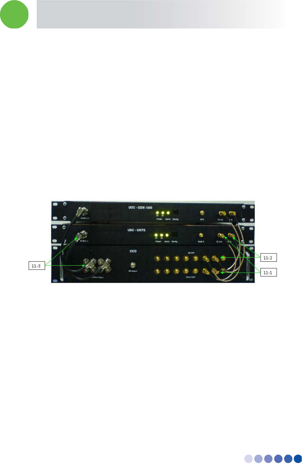
9.3 Connecting the BreezeCELL Equipment
1. Connect the DL port of the UDC to the CCD Down Link port using a SMA/SMA cable. (Figure 11-1)
2. Connect the UL port of the UDC to the CCD Up Link port using a SMA/SMA cable. (Figure 11-2)
3. Connect the 10 MHz in port of the UDC to the 10 MHz output port in the CCD using a BNC/BNC
cable. (Figure 11-3)
4. Repeat steps 1 – 3 for all UDCs
5. After power up, all LEDs should be green.
Figure 8: Headend Equipment Connections
9.4 Connecting the Monitoring System
1. Connect the PC to the monitor and both to the power outlet
2. Connect the Dry contacts interface Advantech USB-4761 to the USB port at the back of the PC
3. Connect the PC to the CCD serial port (on the back) using a DB9 serial cable (male to female)
4. Connect the female side of the DB9 cable to the PC serial port (light blue colored with the symbol
IOIOI)
5. Connect the male side of the DB9 cable to the serial port on the back of the CCD
In-building Cellular Solution for Commercial Buildings UDC Software Configuration Tool
BreezeCELL 11
9.5 Connecting External Alarms
9.5.1 UDCs
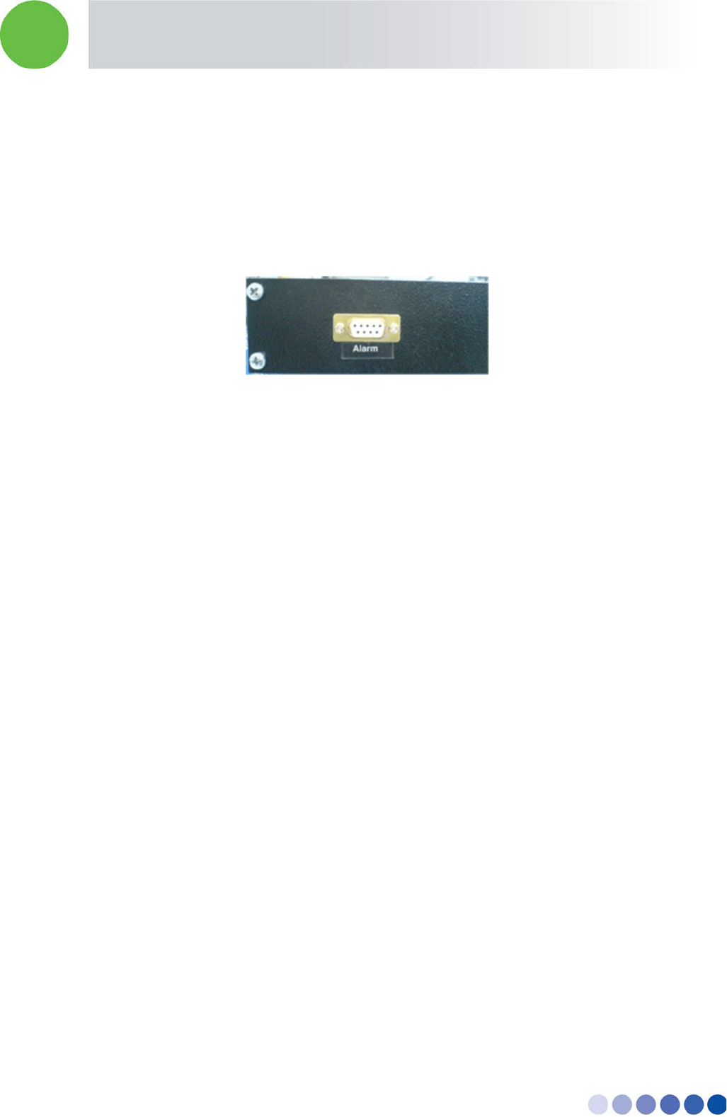
Each UDC is equipped with an external alarm output at the back of the unit. Any UDC failure will light
the Alarm LED on the front panel and trigger the dry contact whose output is at the back. The alarm is
normally closed and will open once triggered or when there is no power to the UDC. Alarm output is at
pins 2 and 3 of the 9 pin D-type connector. Connect an appropriate cable between the alarm output
and the BTS alarm input (or other input source).
Figure 9: UDC Alarm Output
9.5.2 Monitoring
The system uses an Advantech USB dry contacts adaptor for alarm indications.
Relay #0 – provides alarm for a single remote unit failure
Relay #1 – provides alarm for a multiple remote units failure
Single remote unit alarm: For a Normally closed operation connect NC0 and COM0 to the relevant BTS
alarm port
Multiple remote units alarm: For a Normally closed operation connect NC1 and COM1 to the relevant
BTS alarm port
9.6 Connecting the Base Stations
UDC input power range is +10 dBm to +33 dBm. The BTS/Node B output power should be adjusted to
meet this requirement. In case BTS power exceeds the requirement an external attenuator should be
connected
Note: Only the downlink path should be attenuated!
In case of a combined up/down links, it is advisable to split between uplink and downlink paths, and
place the attenuator on the downlink path only.
Connect the output of the BTS/Node B to the appropriate BTS/Node B connector in the relevant UDC
(An N-to-SMA or other adaptor might be required according to the BTS output connector).
9.7 UDC Configuration
UDCs are pre-configured at the factory. In case a change of configuration is required the units are
capable of configuring the BTS attenuation and the gain control. Setting requires removal of the UDC
cover.
In-building Cellular Solution for Commercial Buildings UDC Software Configuration Tool
BreezeCELL 12
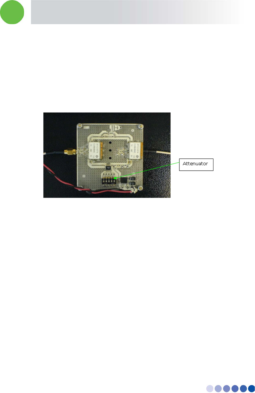
9.7.1 BTS Attenuation Setting
The UDC input power is limited. An internal attenuator allows inputs of +10 dBm to +33 dBm. In case
the output is larger a separate attenuator on the downlink only is required.
Switches represent values of: 1, 2, 4, 8, 16 dB.
The left most switch has the highest attenuation – 16 dB. The right most switch represents the least
attenuation – 1 dB.
The output level of the downlink cellular signal in the Alvarion band should be 0±1 dBm.
The following figure demonstrates the location of the attenuator:
Figure 10: BTS Attenuator
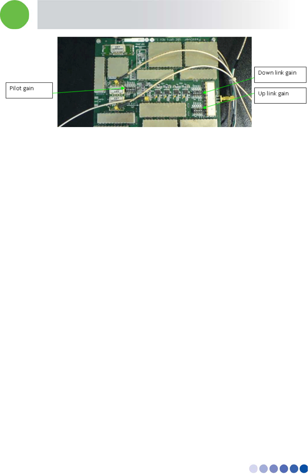
9.7.2 Gain Configuration
The UDC has internal attenuators that allow you to control the Pilot signal level and up link and down
link gains
Switches represent values of: 1, 2, 4, 8, 16 dB.
The left most switch has the highest attenuation – 16 dB. The right most switch represents the least
attenuation – 1 dB.
All signals are pre-configured according to network parameters.
In-building Cellular Solution for Commercial Buildings UDC Software Configuration Tool
BreezeCELL 13
Figure 11: Gain Configuration
If configuration is required:
1. Measure the signal at the UDC DL out port and configure the Pilot signal (962 MHz) to be 0 ± 1
dBm.
2. Measure the cellular downlink signal at the UDC DL out port and adjust it to be 0 ± 1 dBm.
3. Measure the signal at the UDC UL in port and adjust the uplink cellular signal so there is a 0 ± 5 dB
end-to-end Gain (Remote Unit to UDC).
9.7.3 Frequency Configuration
UDC frequency configuration is required in the event the UDC is not pre-configured with the correct
operating frequencies. Using the configuration software is described in appendix A.
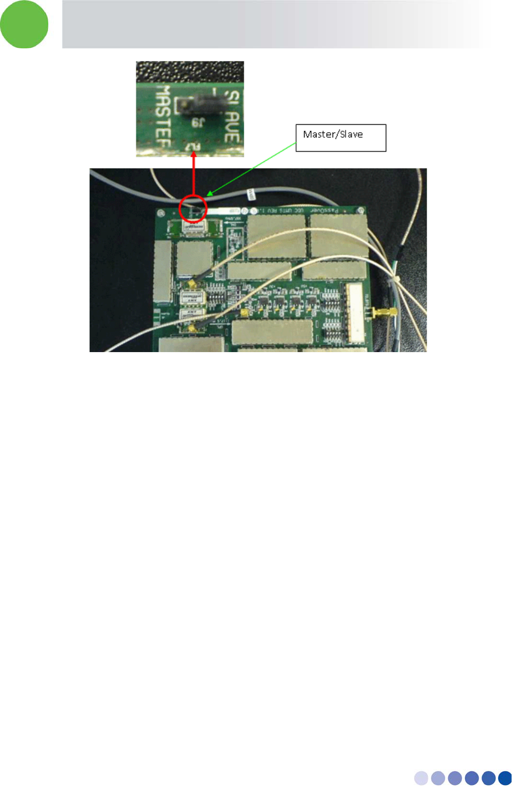
9.8 Pilot Master/Slave Configuration
When working with multiple UDCs only one pilot signal should be generated. Therefore one UDC
should be configured as Master and the rest as Slaves.
Note: The power to the UDC and CCD units should be disconnected before performing the following
procedure.
Locate the Master/Slave jumper on the further left corner of the main UDC circuit board. There are
three pins. Place the jumper (J9) on the left and middle pins for Master. Place the jumper (J9) on the
right and middle pins for Slave.
In-building Cellular Solution for Commercial Buildings UDC Software Configuration Tool
BreezeCELL 14
Figure 12: Master/Slave Configuration
9.9 Measurements
Required test equipment is a spectrum analyzer (capable of measuring both the cable and wireless
frequencies).
In case a BTS/Node B is not available, a signal generator can be used to simulate the signal.
Connect the spectrum analyzer to the DL OUT port of the UDC and verify:
1. Pilot signal at 962 MHz at a 0 ± 1 dBm level.
2. Cellular signal is at the correct frequency (as was configured in the UDC) and at a 0 ± 1 dBm level.
9.10 Connecting to the Coax TV Networks
1. Identify the source of the TV signal.
2. Identify the most convenient point of connection before the first branch.
3. Measure and record the TV signals level with a spectrum analyzer
4. Disconnect the TV source and the building network input.
5. Install a BreezeCELL input diplexer to combine the wireless signal from the BreezeCELL network to
the coax TV network:
6. Connect the diplexer AMPLIFIER port to the coax TV source
7. Connect the diplexer RPT port to the CCD RF OUTPUT port
In-building Cellular Solution for Commercial Buildings UDC Software Configuration Tool
BreezeCELL 15
8. The diplexer CABLE port now carries the combined TV and wireless signal. Connect the CABLE port
the to the building coax network input
Note: The diplexer AC port will be in use only when the coax network is self powered by a 60 VAC
source.
9.11 Measurements
Use a spectrum analyzer to verify that the CABLE output of the diplexer includes the cellular, pilot and
TV signals at their respective power levels as measured in sections 7.9 and 7.10.
9.12 Localized Testing Port
The CCD is equipped with an ability to locally test the BTS connectivity and proper remote unit
operation. The RF Output Monitoring connector in the front of the CCD is a output that is similar to the
CCD RF Output with a -40 dB attenuation. A remote unit can be directly connected to this output to
test the BTS output without the need to disrupt the coax plant.
9.13 Determining BTS Output Power VS. Remote Unit Output
Power
BreezeCELL remote units are offered with two output power settings: 0 dBm and 10 dBm. The remote
unit output power setting is per carrier. The system maintains constant linear gain between the BTS and
the remote unit, thus enabling the BTS/MS power control mechanism to operate normally. The BTS
power output should be configured not to exceed the UDC input power specification.
Example:
GSM BTS with a 46 dBm output power.
External downlink attenuation between BTS and UDC (Attenuation at UDC input)
UDC internal attenuation set at 20 dB
Remote unit output power 10 dBm (per carrier)
GSM BCCH is measured at 0 dBm at the output of the UDC
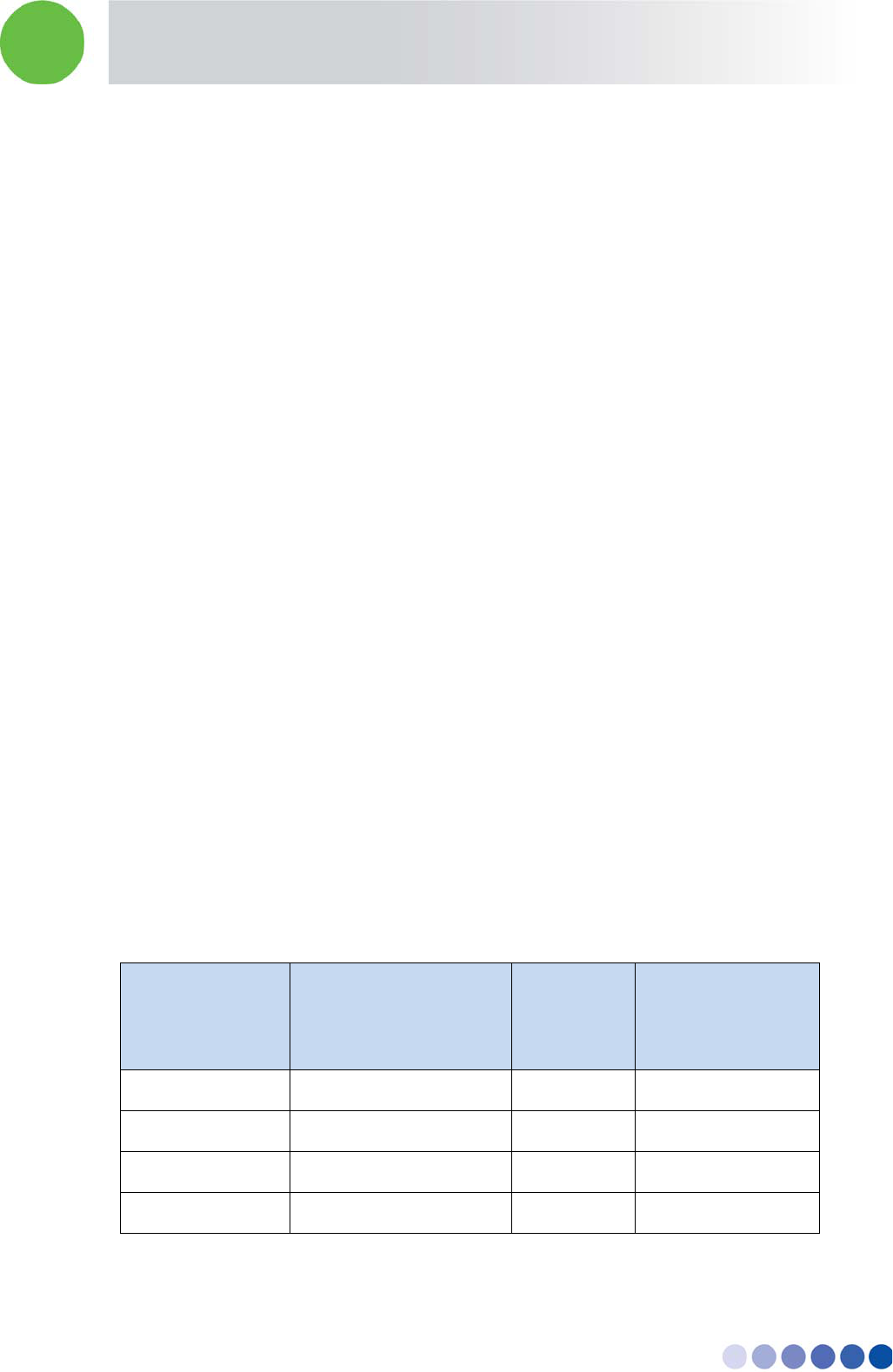
Number of
Carriers
Attenuation at UDC
Input [dB]
UDC Output
[dBm]
Remote Unit
Output Power
[dBm]
1 26 0 10
2 23 3 13
4 20 6 16
8 17 9 19
In-building Cellular Solution for Commercial Buildings UDC Software Configuration Tool
BreezeCELL 16
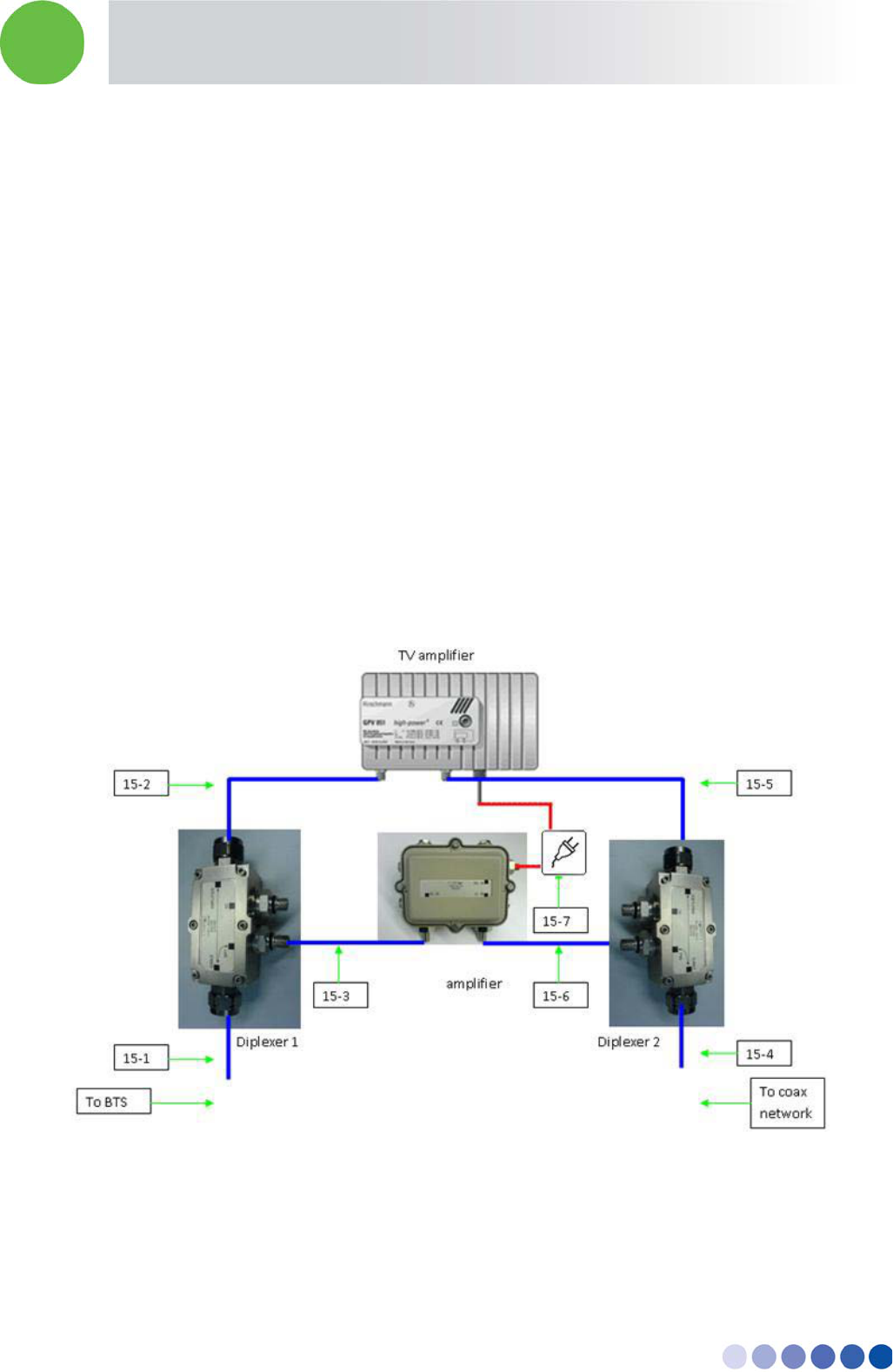
10 Coax Network Amplifier Installation (if applicable)
The coax plant includes amplifiers that compensate the TV signal for the cable loss. A wireless amplifier
should be installed in parallel to each TV amplifier. A set of two diplexers (bypass filters) and an
amplifier is required for every TV amplifier.
10.1 Connections
All connection are done using an F-male to F-male cable
1. Disconnect the input of the TV amplifier and connect it to the CABLE port of diplexer 1. (Fig. 15-1)
2. Connect the AMPLIFIER port diplexer 1 to the input port of the TV amplifier. (Fig. 15-2)
3. Connect the RPT port to the BreezeCELL amplifier DL IN port. (Fig. 15-3)
4. Disconnect the coax network cable from the output port of the TV amplifier and connect it to
diplexer 2 CABLE port. (Fig. 15-4)
5. Connect the output port of the TV amplifier to the AMPLIFIER port of diplexer 2. (Fig. 15-5)
6. Connect the RPT port of diplexer 2 to the UL IN port of the BreezeCELL amplifier. (Fig 15-6)
7. Connect the BreezeCELL amplifier to the power grid using the 7.5 VDC power supply. (Fig. 15-7)
Figure 13: BreezeCELL Amplifier and Diplexer Connection
In-building Cellular Solution for Commercial Buildings UDC Software Configuration Tool
BreezeCELL 17
10.2 Testing and Measurements
1. Measure the cellular downlink signal at the UL IN port of the amplifier (The amplified downlink
signal). Verify existence of the pilot signal at 962 MHz and of the cellular signal. Both signals
should be at a 0 ± 3 dBm level
2. Verify that there is no degradation to the TV signal at the output of diplexer 2.
11 Remote Unit Installation
11.1 Remote Unit Registration
Each new remote unit should be registered in the monitoring system data base (See chapter 10) PRIOR
to installation.
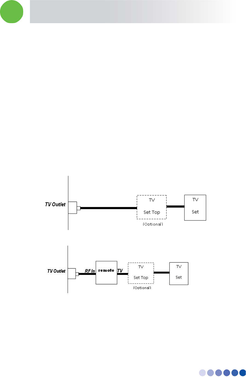
11.2 Remote Unit Connection (if Applicable)
The remote unit is installed in series to the TV, between the TV (or Set Top box) and the wall outlet.
The remote unit should be installed according to the following diagram:
Standard TV connection (before remote unit installation):
Remote unit connection:
Figure 14: Remote Unit Connection
11.3 Remote Unit Installation Kit
Remote unit
AC/DC Power Supply: AC Input - 100-240V, 50/60Hz; DC Output – 5.7 VDC, 3.5 A
In-building Cellular Solution for Commercial Buildings UDC Software Configuration Tool
BreezeCELL 18
Coaxial Cable (F-Type Connectors)
Power Supply (provided separately), complying with the following specifications:
Certified to the EU market:
According to EN/IEC 60950-1 (LPS evaluated)
Rated Input: 100-240VAC, 0.5-0.17 A, 50 or 60 Hz
Rated Output: 5.7 ± 0.5 VDC, 2.7 A
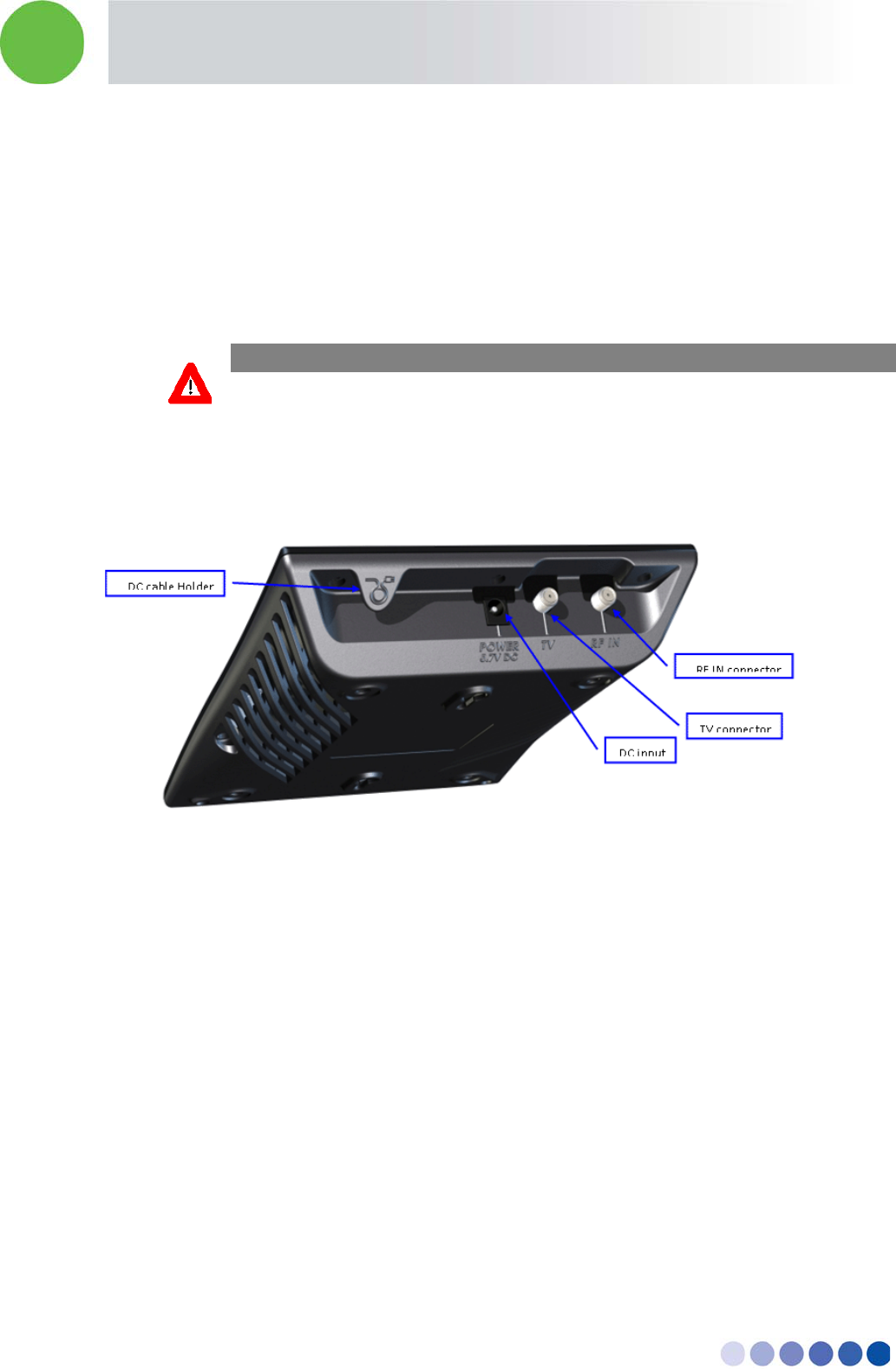
11.4 Installation and Testing Procedure
Figure 15: Remote Unit Rear View
1. Turn off the TV and the TV Set Top Box (if exists)
2. Identify the Coaxial Cable that is connected between the Cable TV Outlet and the TV or the Set
Top Box. Disconnect this cable from the TV or Set Top Box and connect it to the RF IN connector of
the remote unit.
3. Connect the TV connector of the remote unit to the TV or the Set Top Box with a Coaxial cable
(included in the Installation Kit). Turn on the TV (and the TV Set Top Box).
4. Connect the Power Supply (included in the Installation Kit) to the DC Input of the remote unit.
Secure the DC cable using the DC cable holder. Connect the Power Supply to the electrical socket.
5. Verify that the LED on the remote unit’s front illuminate. The LED should turn orange and after a
few seconds turn green.
6. Verify that the reception of TV programs is in order.
CAUTION
Use only the power supply provided with the installation kit

In-building Cellular Solution for Commercial Buildings UDC Software Configuration Tool
BreezeCELL 19
11.5 Remote Unit Configuration
The remote unit will automatically receive all the configuration data from the monitoring system. The
remote unit will not start transmitting before receiving acknowledgment from the monitoring system
that the parameters loaded into its memory are valid.
In the case of a power down, once power restored the remote unit will wait 1 minute before starting to
transmit with its initial configuration parameters.
11.6 Normal Operation
The remote unit LED should be green.
11.7 Recommended Measurements
11.7.1 Testing the First Remote Units
It is advised to perform the following measurements for the first few remote units installed in the
network to verify proper operation:
1. Measure signal levels at the coax cable connection between the wall outlet and the remote unit.
The pilot and the cellular signals should be visible at levels between -20 dBm to – 50 dBm
(dependant of the coax length in this specific network branch)
2. In case a remote unit with external RF outputs is available, measure that the output power is 10
dBm (as specified) and the RF output is at the correct cellular frequency
11.7.2 Standard Remote Unit Testing
For all remote units perform the following:
1. After installing the remote unit, verify the LED is green
Using dedicated cellular test equipment (Handset with test mode or specialized h/w)
2. Measure the cellular downlink signal.
3. Generate a call and test: coverage quality (walk test), call quality and uplink transmit power
4. In case there is a problem perform the measurements in section 9.7.1 for further troubleshooting
12 Preparing for Remote Unit Installation
All operation and maintenance actions are done through the monitoring system. The monitoring
system is a web based application residing on a local PC which serves as a web server.
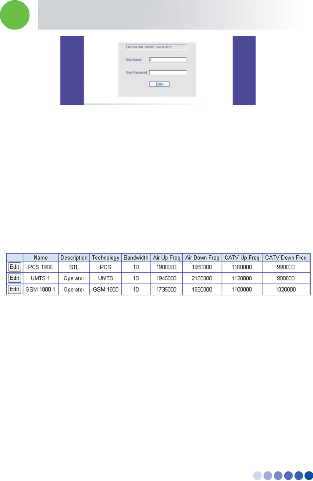
12.1 Logging into the Monitoring System
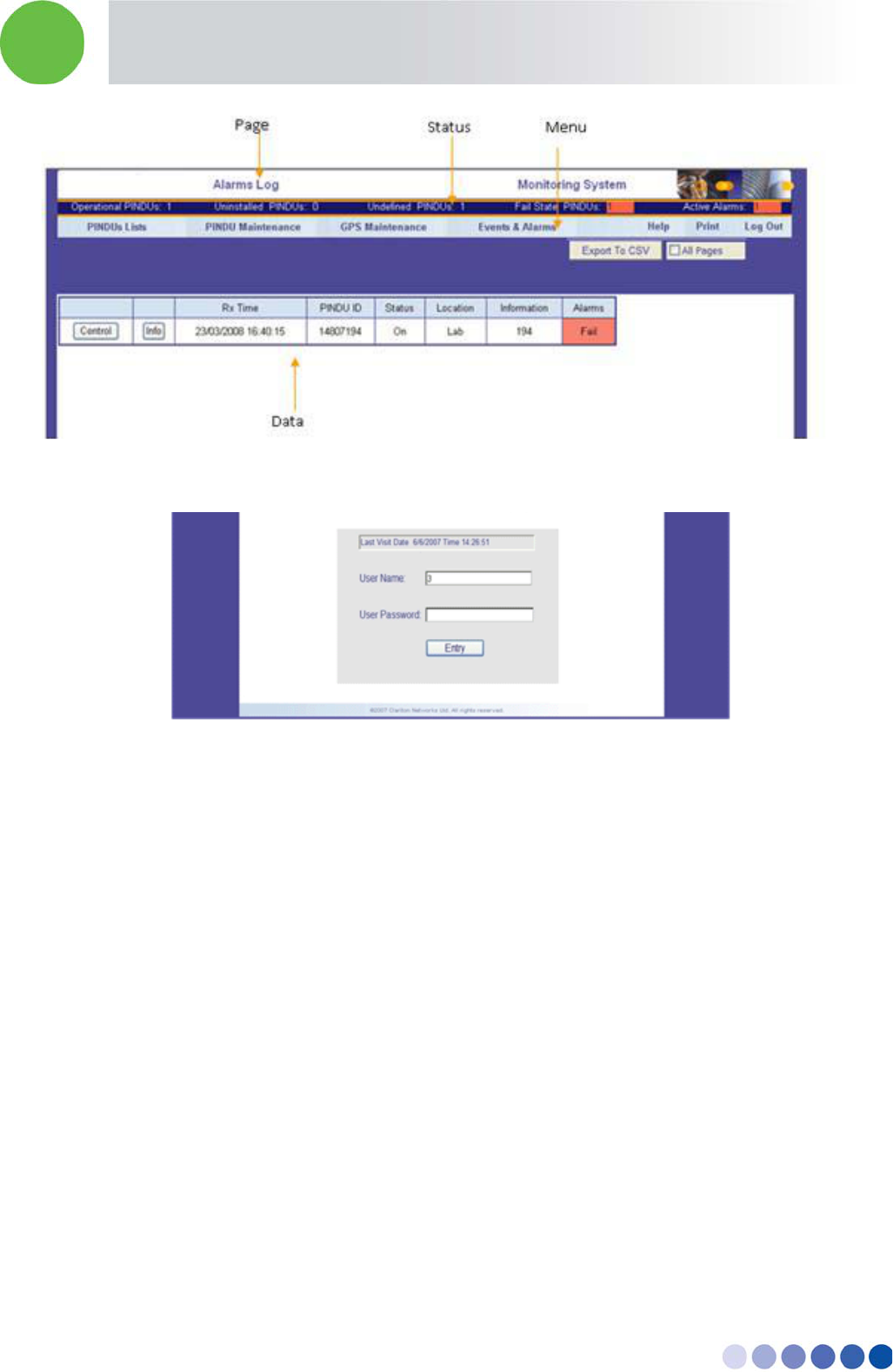
Upon activation of the system, the user will be directed to the entry screen and prompted to enter User
Name and User Password. Enter the login information to enter the system.
In-building Cellular Solution for Commercial Buildings UDC Software Configuration Tool
BreezeCELL 20
After logging in, the main screen will be the Alarms Log.
12.2 Configuring a Global Parameter Set (GPS)
A group of remote units with the same frequency requirements should be allocated a common
parameter set called GPS. Each GPS include:
Cellular (Air) Up Link Frequency
Cellular (Air) Down Link Frequency
CATV Up Link Frequency
CATV Down Link Frequency
A change in the GPS will generate a change in each remote unit using this GPS.
Note: You can’t edit the GPS name, as this is used by its associated remote units
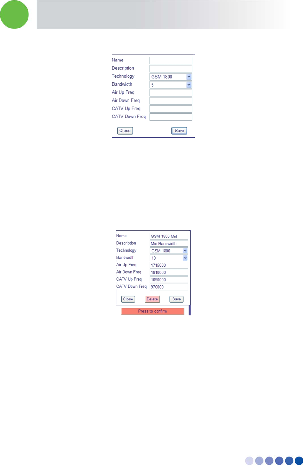
12.2.1 Adding a GPS
1. From the menu GPS MAINTENANCE choose Add Group Parameters
2. Press the ADD GPS button on the top left side of the screen. The GPS configuration table will
appear.
3. Enter a Name and Description of the GPS. The name should be unique.
4. Choose the technology from the list: GSM 900, GSM 1800, UMTS, PCS, iDEN, US Cellular
5. Choose the channel Bandwidth of the remote unit (factory hardware preset)
6. Fill in the Cellular and CATV frequencies according to your frequency plan so that there is a match
with the channel bandwidth and the technology. The frequency units are [KHz]
7. Press Save to update the database
8. Repeat steps b to g for each GPS required in the network
In-building Cellular Solution for Commercial Buildings UDC Software Configuration Tool
BreezeCELL 21
In the case of a dual technology remote unit, two separate GPSs are required for the remote unit to be
fully operational.
12.2.2 Deleting a GPS
Note: You should delete a GPS only if there are no remote units that belong to this GPS!
1. From the menu GPS MAINTENANCE choose View Group Parameters
2. Press the EDIT button of the relevant GPS
3. Press the DELETE button
4. Press the confirmation button
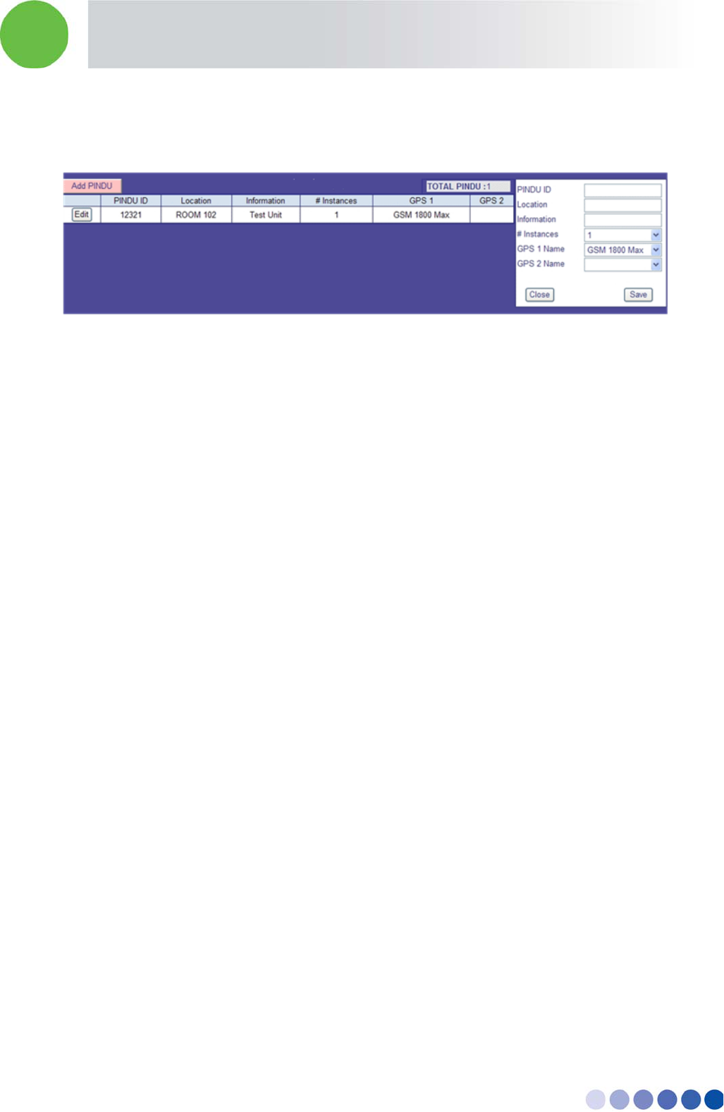
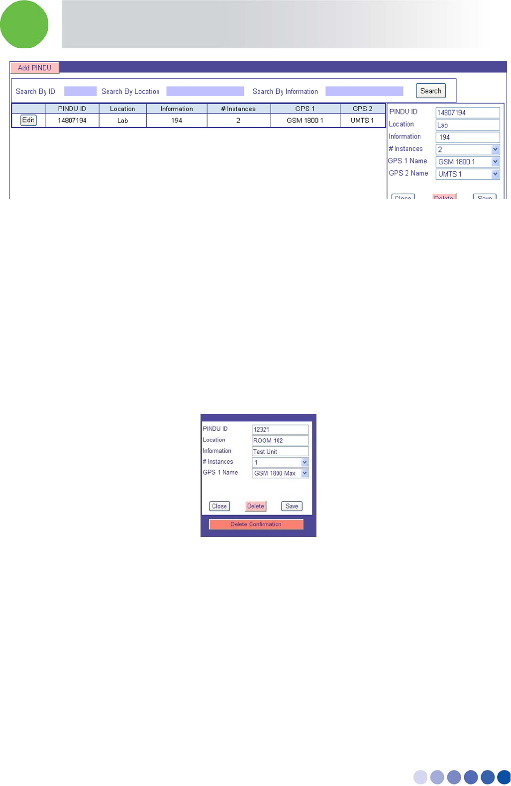
12.3 Adding and Registering a New Remote Unit
Each remote unit installed in the network should be defined and registered prior to installation.
1. From the remote unit MAINTENANCE menu choose Edit/Add remote unit
2. Press the Add remote unit button on the top left side of the screen. The remote unit configuration
table will appear.
3. Input all remote unit parameters:
Remote unit ID = serial number
Location [Free text]
Information [Free text]
In-building Cellular Solution for Commercial Buildings UDC Software Configuration Tool
BreezeCELL 22
Number of instances - single [1] or dual technology [2]
GPS1 & GPS2 – choose from defined GPS list
4. Press the Save button to input the remote unit into the database
12.4 Installing a Remote Unit
Once a remote unit is installed in the field, it will communicate with the monitoring system and will
receive operational configuration parameters. There are two possible scenarios:
Uninstalled remote unit – a remote unit which is defined in the database
Undefined remote unit – a remote unit which was not previously defined in the database
12.4.1 Uninstalled Remote Unit
Adding a new remote unit into the database will generate an uninstalled remote unit entry. This refers
to a remote unit that was properly defined in the system and should be installed in the field. At the
moment the remote unit is physically installed, it communicates with the monitoring system, all
parameters are verified and downloaded to the remote unit, after that the remote unit receives a
permission to radiate.
12.4.2 Undefined Remote Unit
A remote unit that was physically installed in the field, but was not entered into the database prior to
installation. Such a remote unit will be transferred to the undefined remote unit s list and requires
operator configuration of the relevant parameters in the monitoring system to become operational.
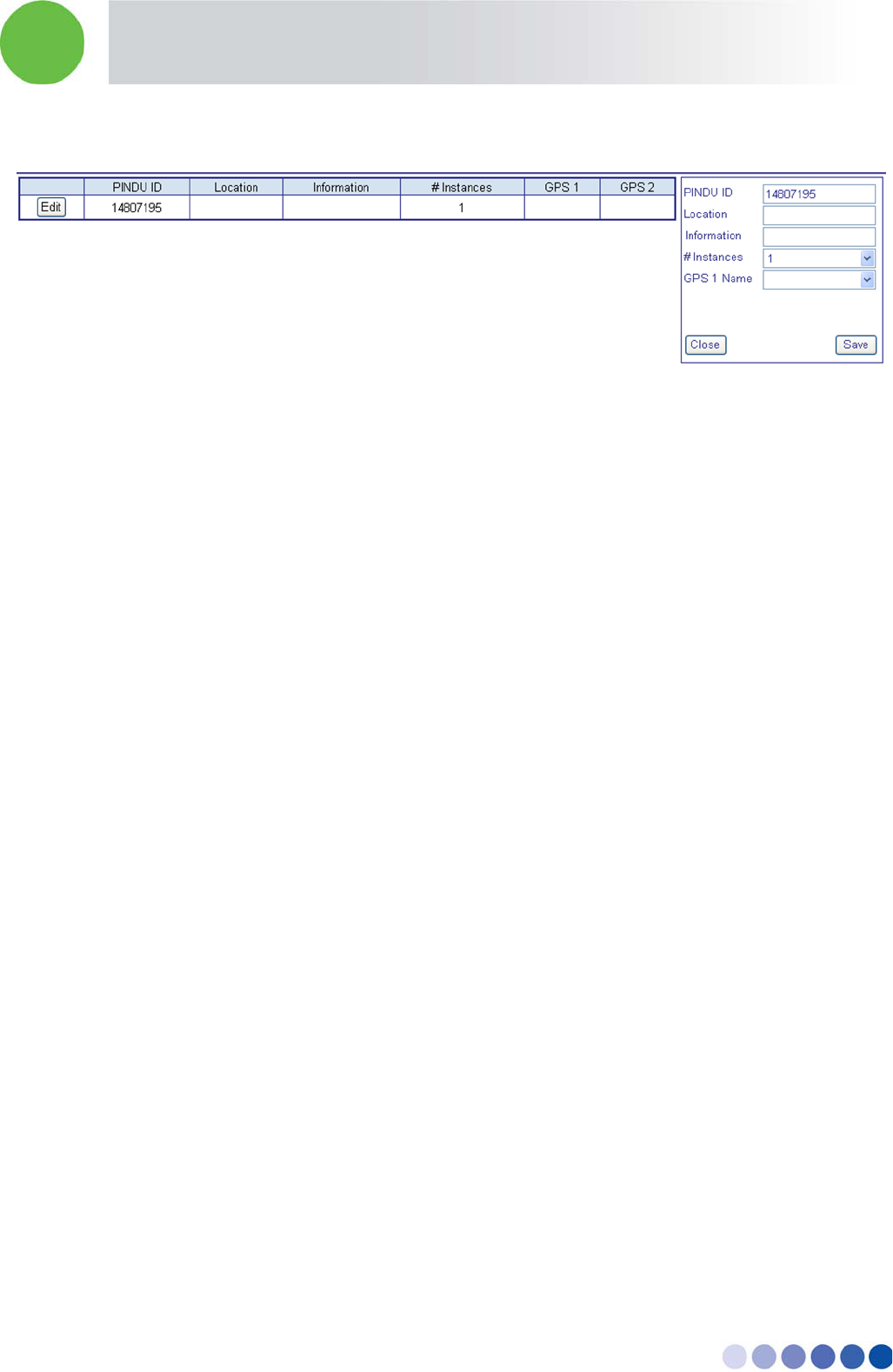
12.4.3 Adding an Undefined Remote Unit into the Database
1. From the remote units Lists menu choose Undefined remote units
2. Choose the relevant remote unit from the list and press the EDIT button on the left side of the
remote unit entry. A configuration screen will appear.
3. Enter the remote unit information
Location [Free text]
Information [Free text]
Number of instances - single [1] or dual technology [2]
In-building Cellular Solution for Commercial Buildings UDC Software Configuration Tool
BreezeCELL 23
GPS1 & GPS2 – choose from defined GPS list
4. Press the Save button to input the remote unit into the database.
12.4.4 Deleting an Undefined Remote Unit from the List
1. From the remote units Lists menu choose Undefined remote units
2. Choose the relevant remote unit from the list and press the EDIT button on the left side of the
remote unit entry. A configuration screen will appear.
3. Press the Delete button
4. Press the Confirmation button to confirm
13 Normal Operations
To start the program, perform the following steps:
Turn the PC on and log in if necessary
The S.N.A.P monitor software will start-up automatically. In case the monitor software has been
manually closed it can be activated again using the monitor short cut on the desktop.
Start the Internet explorer application by double clicking on the desktop icon
The system enables the operator to perform the following tasks
View the network current status (Alarms, Events, remote unit status)
Perform commands on a specific remote unit
Perform commands on all the remote units in the network simultaneously
In-building Cellular Solution for Commercial Buildings UDC Software Configuration Tool
BreezeCELL 24
13.1 Logging into the Monitoring System
Upon activation of the system, the user will be directed to the entry screen and prompted to enter User
Name and User Password. Enter the login information to enter the system.
After logging in the main screen will be the Alarms Log
13.2 The Status Bar
On the top of the screen there is a status bar which remains visible in all the screens. The Status Bar
provides immediately available information for the operator regarding:
Number of Operational remote units
Number of Uninstalled remote units
Number of Undefined remote units
Number of Failed remote units
Number of Active Alarms
13.3 Viewing Remote Units Status
The operator can view a list of all operational remote units status and configuration or alternatively look
at a single remote unit.
In-building Cellular Solution for Commercial Buildings UDC Software Configuration Tool
BreezeCELL 25
13.3.1 Viewing the Operational Remote Units Status
1. From the remote units Lists menu choose Operational remote units.
2. The screen will display a list of all operational remote units with the following parameters for each
one:
Status of communication with remote unit
Time and date of last status update
Remote unit ID – remote unit serial number
General Status – remote unit On/Off
Pilot Lock – System Pilot signal reception OK/Fail
Gain – Input to output gain setting
Instances – Single or Dual band
Instance 1 Status – On/Off
Instance 1 Synthesizer Lock Status – OK/Fail
Instance 1 Technology – GSM 900/GSM 1800/UMTS/PCS/iDEN/US Cellular
Instance 2 Status – On/Off
Instance 2 Synthesizer Lock Status – OK/Fail
Instance 2 Technology – GSM 900/GSM 1800/UMTS/PCS/iDEN/US Cellular
3. On the left side of each remote unit entry there is an INFO button. Pressing the view button will
show the full detail list for the chosen remote unit.
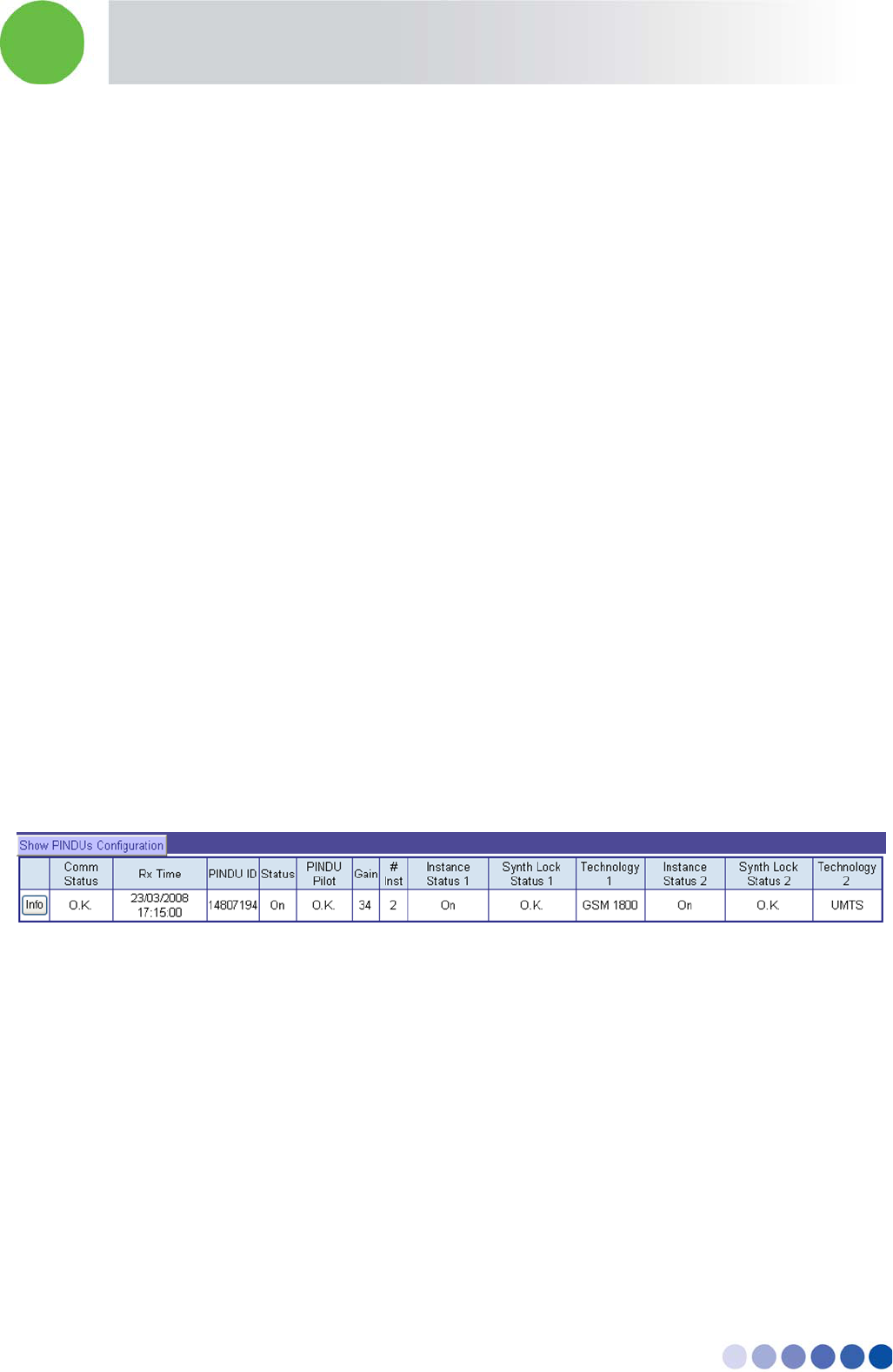
13.3.2 Viewing the Operational Remote Units Configuration
1. In the Operation remote unit status screen press the button: Show remote units Configuration
2. The screen will display a list of all operational remote units with the following parameters for each
one:
Status of communication with remote unit
Time and date of last status update
Remote unit ID – remote unit serial number
Location – Operator entered free text
Information – Operator entered free text
In-building Cellular Solution for Commercial Buildings UDC Software Configuration Tool
BreezeCELL 26
Hardware version
Software version
Communication protocol version
Output power type – 0 dBm or 10 dBm
Instances – Single or Dual band
GPS 1 – Global Parameter Set for instance 1
GPS 2 – Global Parameter Set for instance 2
3. On the left side of each remote unit entry there is an INFO button. Pressing the view button will
show the full detail list for the chosen remote unit.
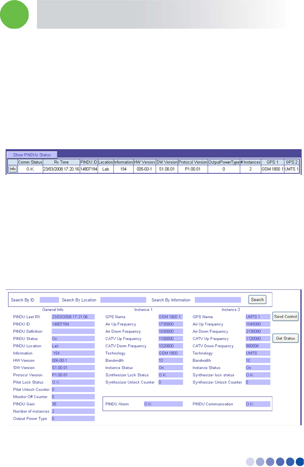
13.3.3 Viewing the Complete Information of a Single Remote Unit
1. From the Operational remote unit screens, press the info button
2. Alternatively, from the remote unit Maintenance menu choose remote unit Information
3. Search for the relevant remote unit according to the remote unit ID/Location/Information
4. The chosen remote unit will be displayed with complete information
5. The remote unit info can be refreshed by pressing the GET STATUS button
6. The remote unit can be controlled by pressing the SEND CONTROL button. This action will link to
the remote units commands page with the chosen remote unit
The following information is available for each remote unit:

In-building Cellular Solution for Commercial Buildings UDC Software Configuration Tool
BreezeCELL 27
Time and date of last status update
Remote unit ID – remote unit serial number
Remote unit Definition – Operational/Uninstalled/Undefined
General Status – remote unit On/Off
Location – Operator entered free text
Information – Operator entered free text
Hardware version
Software version
Communication protocol version
Pilot Lock – System Pilot signal reception OK/Fail
Pilot Unlock counter – the number of Pilot unlock occurrences since last counter reset
Monitor off counter – the number of monitor unlock occurrences since last counter reset
Remote unit Gain – Input to output gain setting
Instances – Single or Dual band
Output power type – 0 dBm or 10 dBm
For each instance the following parameters:
GPS name – Global Parameter Set for instance
Air Up Frequency – Wireless uplink frequency
Air Down Frequency – Wireless downlink frequency
CATV Up Frequency – Cable allocation uplink frequency
CATV Down Frequency – Cable allocation downlink frequency
Instance Technology – GSM 900/GSM 1800/UMTS/PCS/iDEN/US Cellular/WiMAX
Instance Status – On/Off
Instance Synthesizer Lock Status – OK/Fail
Instance Synthesizer unlock counter – the number of synthesizer unlock occurrences since last
counter reset
Global alarms:
Remote unit ALARM – a sum of all remote unit alarms
Remote unit Communication – status of communication between PC and remote unit
In-building Cellular Solution for Commercial Buildings UDC Software Configuration Tool
BreezeCELL 28
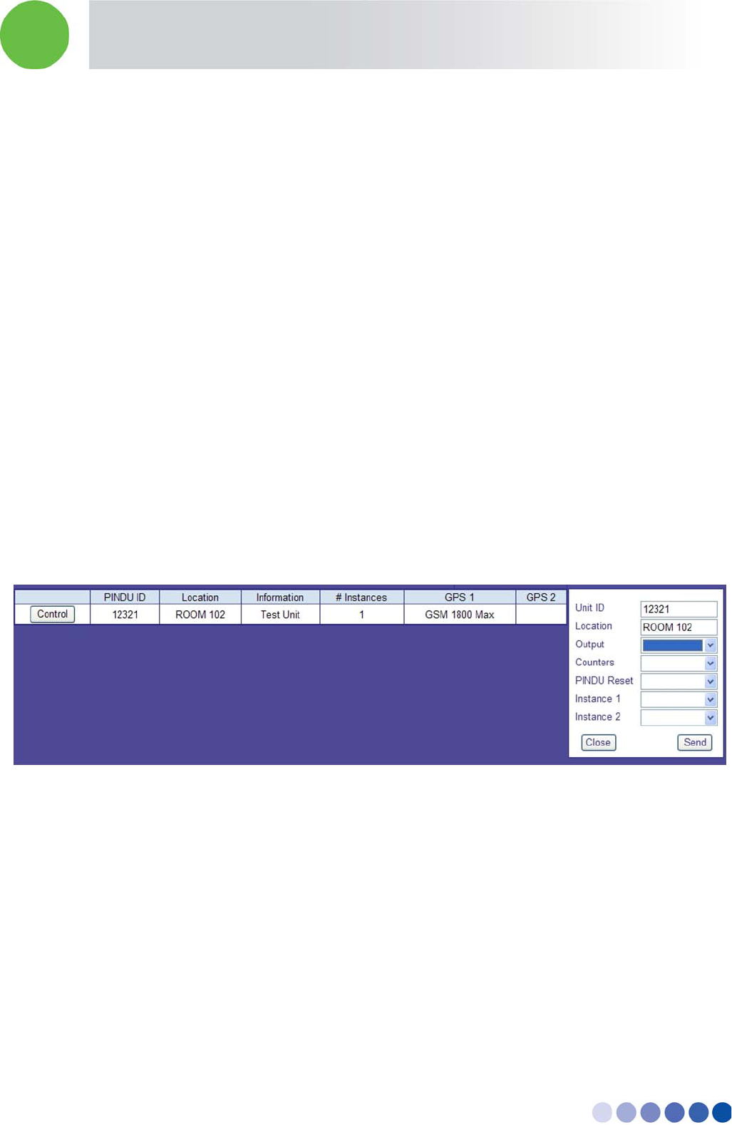
13.4 Controlling Remote Units
13.4.1 Controlling a Single Remote Unit
1. From the INFO page press SEND CONTROL
2. Alternatively, from the remote unit Maintenance menu choose remote unit Commands
3. Search for the relevant remote unit according to the remote unit ID/Location/Information
4. The chosen remote unit will be displayed with configuration information
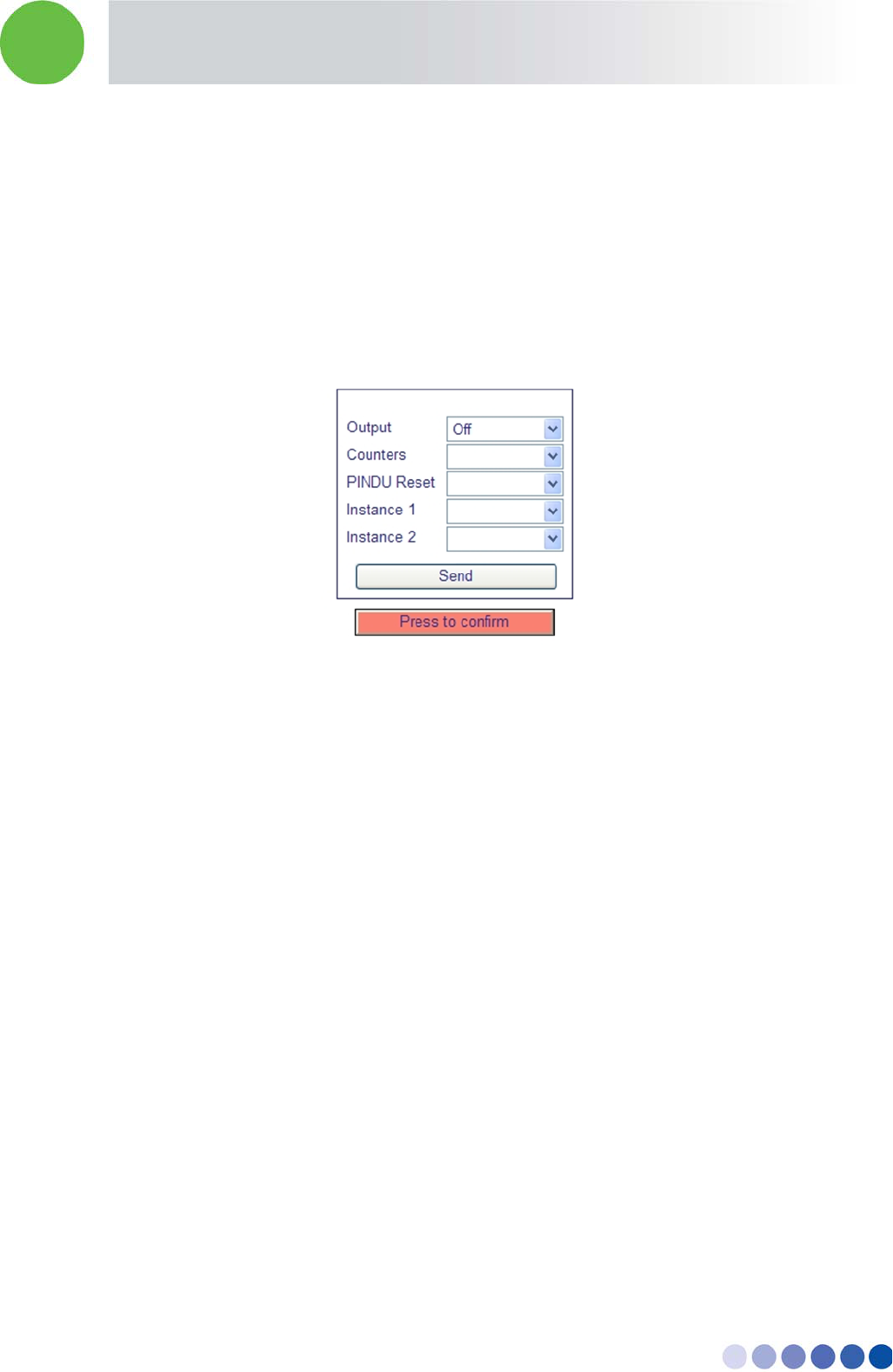
5. Press the CONTROL button on the left side of the row. A window will open.
6. Choose the required Command
OUTPUT - remote unit RF Output Enable – On/Off
Counters – Reset all unlock counters (Pilot/Synthesizers/monitor)
Remote unit Reset – Reset the remote unit software
Instance 1 – Turn instance 1 output RF off
Instance 2 Reset – Turn instance 2 output RF off
7. Press the SEND button
Note: Only a single command can be issued!
13.4.2 Issuing a Global Command
A global command affects all the remote units in the network.
1. From the remote unit Maintenance menu choose Global Commands
2. Choose the required Command
Remote unit RF Output Enable – On/Off
Counters Reset– Reset all unlock counters (Pilot/Synthesizers)
Remote unit Reset – Reset the remote unit software
Instance 1– Turn instance 1 output RF off
In-building Cellular Solution for Commercial Buildings UDC Software Configuration Tool
BreezeCELL 29
Instance 2 – Turn instance 2 output RF off
3. Press the SEND button
4. Press the CONFIRMATION button
Note: Global Command may be Service effecting and generate a service down time. Sending a Global
Command will generate a process of communication between all remote units and the Monitoring
system. When performing a Global Command such as RESET, sufficient time should be allowed for all
elements in the system to respond and stabilize. Do not perform any operations for 2 minutes.
Note: Only a single command can be issued!
13.4.3 Editing Remote Unit Configuration
1. From the remote unit Maintenance menu choose Edit/Add remote unit
2. Choose the relevant remote unit from the list
3. Press the EDIT button on the left side of the row
4. An information screen will appear on the right side
5. Modify the required parameters:
Remote unit Location – Free Text
Remote unit Information – Free Text
Number of Instances – Choose the correct option for the remote unit
GPS 1 – Choose the relevant GPS for instance 1
GPS 2 – Choose the relevant GPS for instance 2
6. Press the SAVE button will generate communication to update the remote unit in the field
In-building Cellular Solution for Commercial Buildings UDC Software Configuration Tool
BreezeCELL 30
Note: GPS changes will take place only after resetting the remote unit (see section 3.4 controlling
remote units)
13.4.4 Deleting a Remote Unit from the Database
1. From the remote unit Maintenance menu choose Edit/Add remote unit
2. Choose the relevant remote unit from the list
3. Press the EDIT button on the left side of the row
4. An information screen will appear on the right side
5. Press the DELETE button
6. Press the CONFIRMATION button to delete
Note: Always leave at least one remote unit in the database. The database shouldn’t be empty
13.5 GPS Maintenance
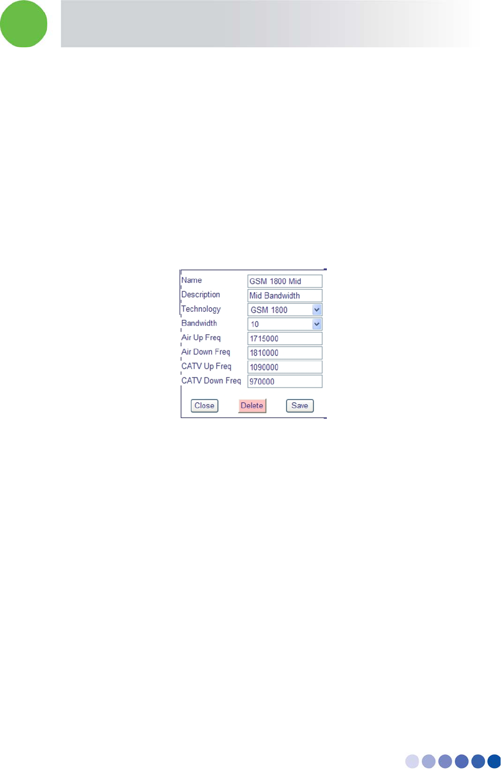
13.5.1 Editing a GPS
1. From the GPS Maintenance menu choose View Global Parameters
2. Choose the relevant GPS from the list
3. Press the EDIT button on the left side of the row
4. An information screen will appear on the right side
5. Modify the required parameters:
In-building Cellular Solution for Commercial Buildings UDC Software Configuration Tool
BreezeCELL 31
GPS NAME – Free Text
GPS Description – Free Text
Technology – Choose between GSM 900/GSM 1800/UMTS/PCS/iDEN/US Cellular/WiMAX 2.5
GHz
Bandwidth – Choose between 5/10/15 MHz
Air Up Frequency – Cellular Receive (middle frequency of band in KHz)
Air Down Frequency – Cellular Transmit (middle frequency of band in KHz)
CATV Up Frequency – Cable Receive (middle frequency of band in KHz)
CATV Down Frequency – Cable Transmit (middle frequency of band in KHz)
6. Press the SAVE button
Note: GPS changes will take place only after resetting the associated remote units (see section 3.4
controlling remote units)
13.5.2 Deleting a GPS from the Database
Note: You should delete a GPS only if there are no remote units that use this GPS!
1. From the GPS Maintenance menu choose View Global Parameters
2. Choose the relevant GPS from the list
3. Press the EDIT button on the left side of the row
4. An information screen will appear on the right side
5. Press the DELETE button
6. Press the CONFIRMATION button to delete
In-building Cellular Solution for Commercial Buildings UDC Software Configuration Tool
BreezeCELL 32
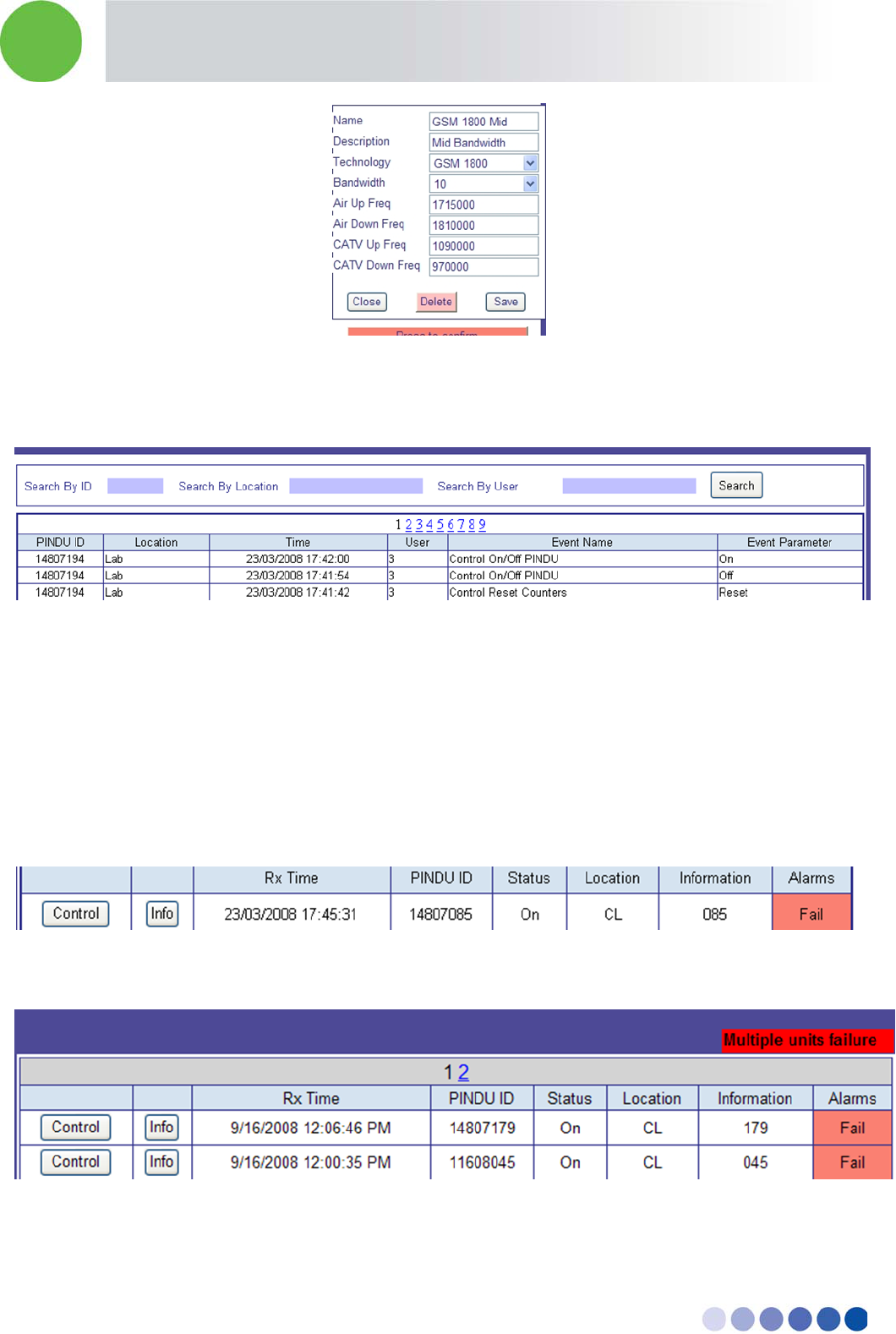
13.6 Events Log
All actions performed in the system are documented in the Event Log
13.7 Alarms Log
The main screen after logging in, is the Alarm Log.
A list of all active alarms is displayed on the screen. According to the amount and details of concurrent
alarms, the operators can analyze the alarm to determine whether the cause is a specific remote unit or
a network problem.
A single remote unit alarm will cause the dry contacts output #0 to change position (from Normally
Closed to Normally Open)
In case of a multiple remote units failure that have crossed the multiple alarm threshold (see section
3.8) a message will appear on the top of the alarm window to indicate Multiple units failure.
A Multiple remote unit alarm will cause the dry contacts output #1 to change position (from Normally
Closed to Normally Open)
In-building Cellular Solution for Commercial Buildings UDC Software Configuration Tool
BreezeCELL 33
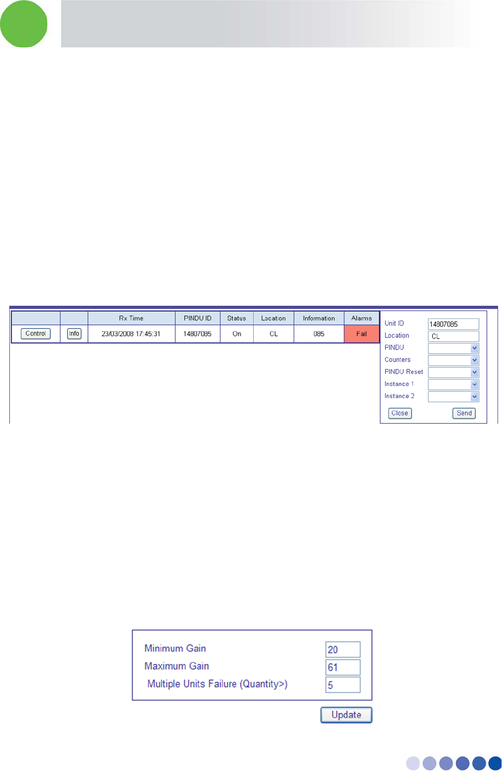
The operator can control the faulty remote unit by pressing the CONTROL button on the left side of the
alarm row. A window will open.
1. Choose the required Command
Remote unit RF Output Enable – On/Off
Counters Reset– Reset all unlock counters (Pilot/Synthesizers)
Remote unit Reset – Reset the remote unit software
Instance 1– Turn instance 1 output RF off
Instance 2– Turn instance 2 output RF off
2. Press the SEND button
3. Go to specific remote unit information screen or check the Operational remote units status to
verify current status.
Note: Only a single command can be issued!
13.8 Alarms Thresholds
Each remote unit periodically transmits its current status to the monitoring system. An alarm is
generated in a case where one of the remote unit status parameters exceeds a threshold defined in the
system. The operator can configure the alarm thresholds to fit the local requirements.
The following parameters can be configured from the Alarm Thresholds screen:
Minimum Gain – Generates an alarm when the remote unit gain is lower than the threshold
Maximum Gain – Generates an alarm when the remote unit gain is higher than the threshold
Multiple Units Failure (Quantity>) – Generates a multiple units alarm whenever the number of failed
units exceeds the threshold
In-building Cellular Solution for Commercial Buildings UDC Software Configuration Tool
BreezeCELL 34
13.9 Exporting the Database
Database can be exported to a CSV (Comma Separated Value) file. This file can be used with programs
such as Microsoft Excel and Access for further analysis and display.
The following information screens can exported to CSV format:
Operational remote units status and configuration screens
Undefined remote units
Uninstalled remote units
View/Add Group Parameters Set (GPS)
Events log
Alarms log
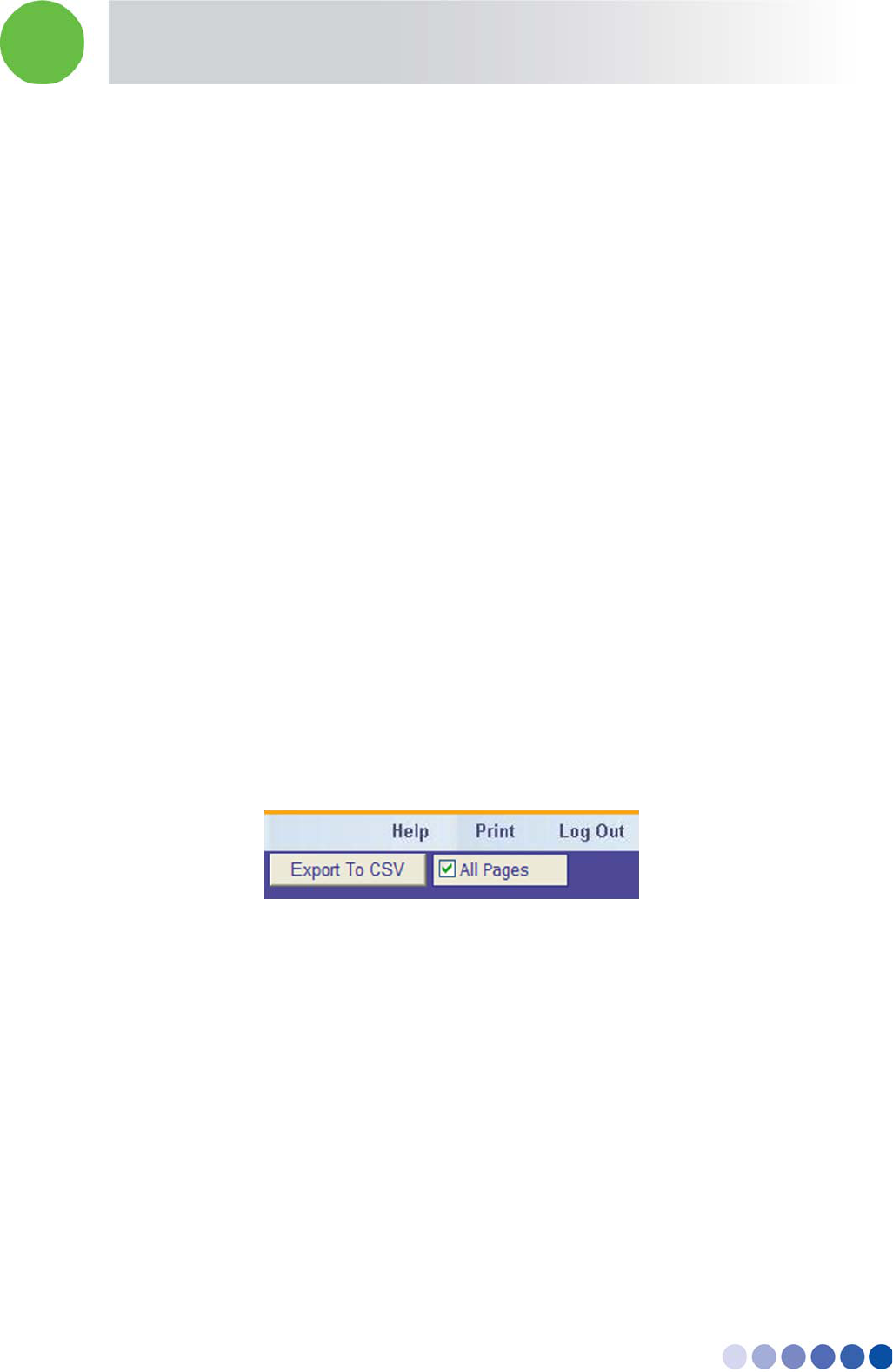
There are two options for the export:
Export the displayed page
Export all pages in the data base
To export the displayed screen
1. Press the Export To CSV button at the top of the data screen
To export all pages in the data base
2. Mark the check box All Pages
3. Press the Export To CSV button
13.10 Database Backup
The application automatically saves a backup of the database every day at midnight (00:00). The
backup files are saved with a date tag attached to the their name for indication.
A corrupted database file can be replaced with the backup database. For further details please contact
your local support office.
Note: replacing a database file with a backup file will result in the loss of all changes made to the
database and all collected database information in between the last backup and the time of
replacement.
In-building Cellular Solution for Commercial Buildings UDC Software Configuration Tool
BreezeCELL 35
14 Acceptance Testing
14.1 Headend Equipment Testing
14.1.1 BTS Output Measurement
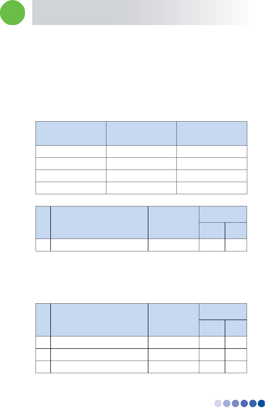
The BTS/Node B output power should be adjusted so that the UDC output port will have a 0 dBm per
carrier.
The UDC is factory configured to have 20 dB attenuation, therefore the BTS/Node B output should be
the following.
Example for GSM – BCCH should be 20 dBm, BTS has 46 dBm composite power.
Number of Carriers Attenuation at BTS
Output (downlink only)
Measured Composite
(after attenuator)
1 26 dB 20 dBm
2 23 dB 23 dBm
4 20 dB 26 dBm
8 17 dB 29 dBm
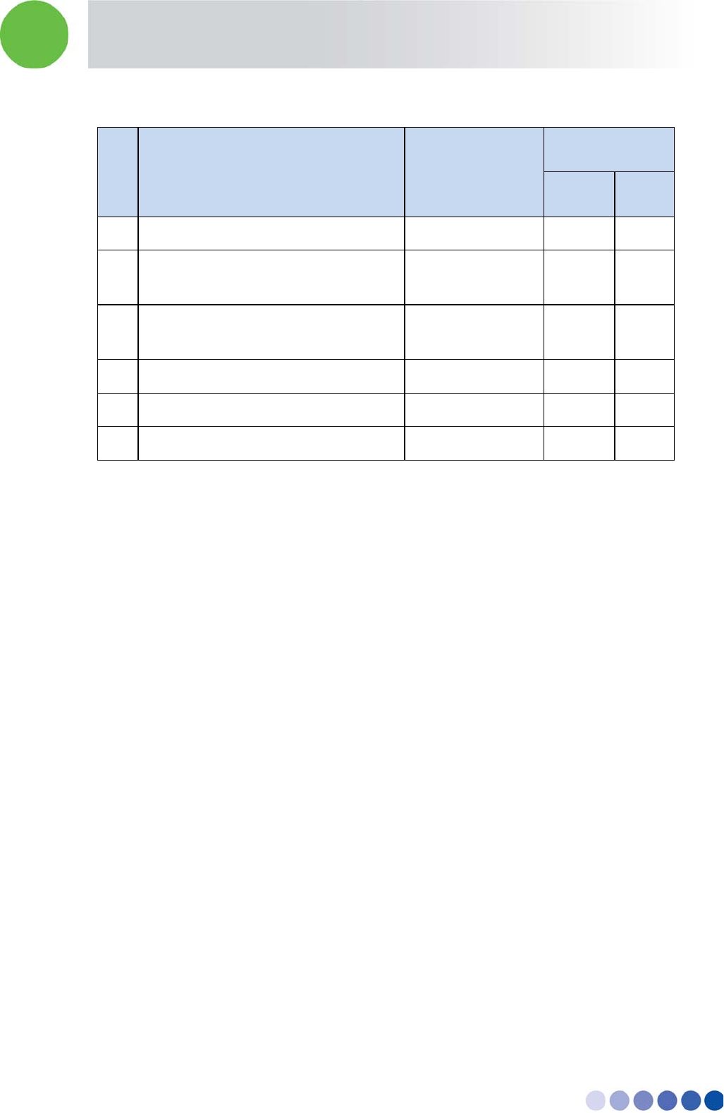
No. Test Operations Test Requirement
Results
Pass Fail
1 Measure BTS/Node B output See 1.1
14.1.2 UDC Testing
1. For each UDC verify that all three LEDs are green
2. Measure the Pilot signal (962 MHz) at the UDC DL out port. The signal should be 0 ± 1 dBm.
3. Measure the cellular downlink signal at the UDC DL out port. The signal should be 0 ± 1 dBm.
No. Test Operations Test Requirement
Results
Pass Fail
1 Examine UDC LEDs All LEDs are Green
2 Measure Pilot signal (962 MHz) 0 ± 1 dBm
3 Measure Cellular signal 0 ± 1 dBm
In-building Cellular Solution for Commercial Buildings UDC Software Configuration Tool
BreezeCELL 36
14.2 Coax Network Amplifier Testing
14.2.1 Amplifier Downlink Signal Measurement
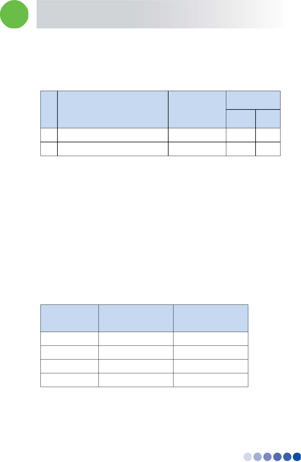
Measure the cellular downlink signal at the UL IN port of the amplifier (The amplified downlink signal).
Verify existence of the pilot signal at 962 MHz and of the cellular signal. Both signals should be at a 0 ±
3 dBm level.
No. Test Operations Test Requirement
Results
Pass Fail
1 Measure Pilot signal (962 MHz) 0 ± 3 dBm
2 Measure Cellular signal 0 ± 3 dBm
14.3 Remote Unit Testing
14.3.1 Remote Unit LEDs
Verify that the LED on the remote unit’s front illuminate. After power up the LED should turn orange
and after a few seconds turn green. In Normal operations LED should be green
14.4 Remote Unit Measurements
14.4.1 Testing the First Remote Units
1. Measure signal levels at the coax cable connection between the wall outlet and the remote unit.
The pilot and the cellular signals should be visible at levels between -20 dBm to – 50 dBm
(dependant of the coax length in this specific network branch)
2. In case a remote unit with external RF outputs is available, measure that the output power is 0 or
10 dBm (according to remote unit type) and the RF output is at the correct cellular frequency
Number of carriers Remote unit output
power (0 dBm model)
Remote unit output
power (10 dBm model)
1 0 dB 10 dB
2 3 dB 13 dB
4 6 dB 16 dB
8 9 dB 19 dB
14.4.2 Standard Remote Unit Testing
For all remote units perform the following:
Using dedicated cellular test equipment (Handset with test mode or specialized h/w)
In-building Cellular Solution for Commercial Buildings UDC Software Configuration Tool
BreezeCELL 37
1. Measure the cellular downlink signal (walk test)
2. Generate a call and test: coverage quality (walk test), call quality and uplink transmit power
No. Test Operations Test Requirement
Results
Pass Fail
1 Verify remote unit LED illuminate Green
2 Measure wall outlet cellular signal * -20 dBm to -50
dBm
3 Measure direct remote unit output
power*
See 3.2.1
4 Outgoing voice call
5 Incoming voce call
6 Data session
14.4.3 Global Walk Test
Using dedicated test equipment such as TEMS perform a complete premises walk test.
In-building Cellular Solution for Commercial Buildings UDC Software Configuration Tool
BreezeCELL 38
Appendix A. UDC Software Configuration Tool
UDC frequency plans are configurable using configuration software and a Alvarion supplied
programmer. The same programmer can also configure 1st generation remote units.
A.1. Requirements
PC/Laptop with a serial port
ICP-01 Programmer
Alvarion configuration software
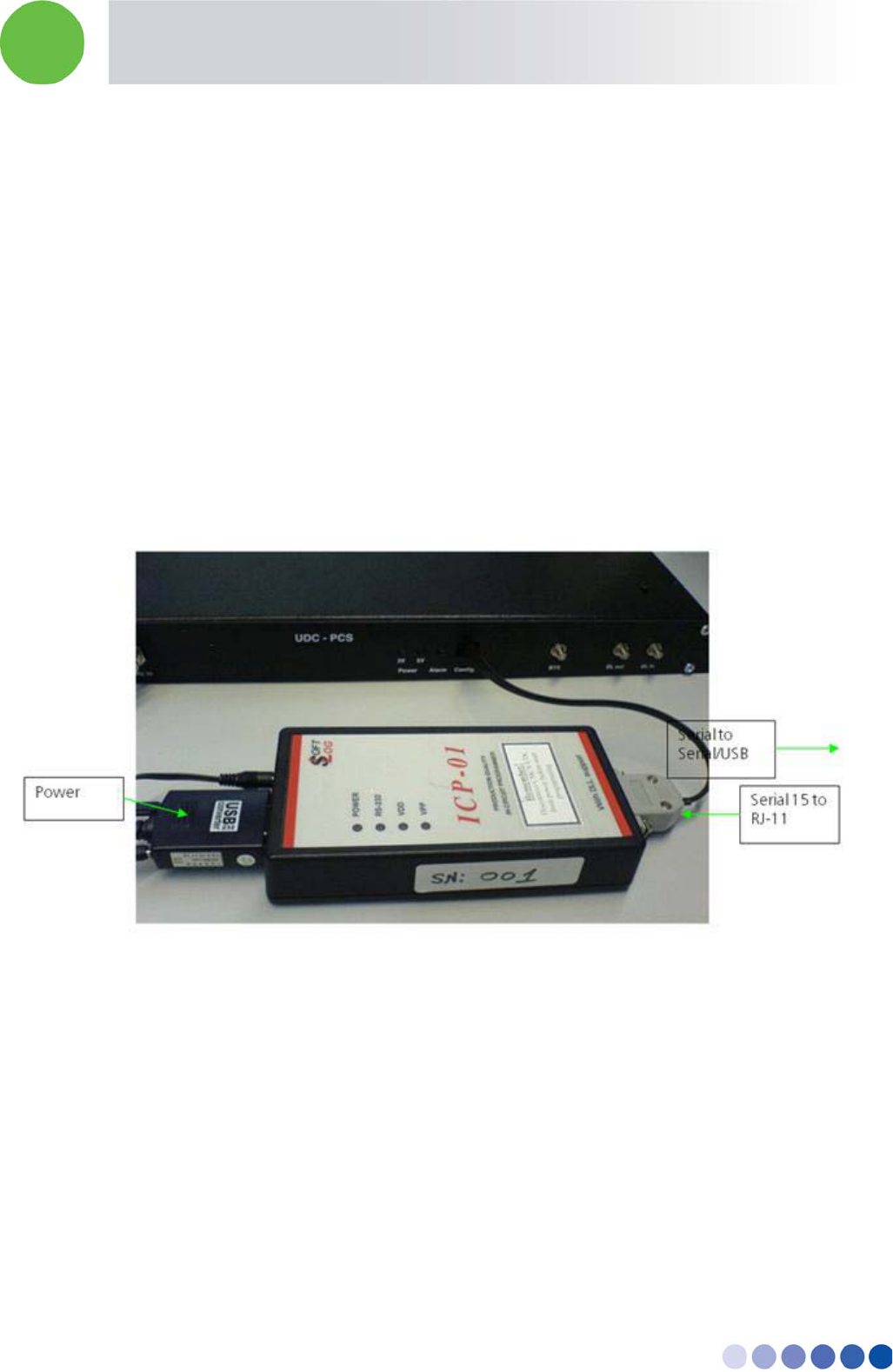
A.2. Connecting the Programmer
The programmer is supplied with two cables:
Serial 9 pin to Serial 9 pin (or USB)
Serial 15 pin to RJ – 11
Figure 16: Programmer Connection
1. Connect the 9 pin serial cable between the programmer serial 9 pin port and a PC serial port
2. Connect the serial 15 to RJ-11 cable. The serial side connects to the programmer data port and the
other side to the programmed device such as the UDC or remote unit.
3. Plug the power supply to the programmer and into the AC mains.
4. The green POWER LED should be lit
5. Note: the programmer uses COM1 on the PC. In case of a conflict with other software please
contact Alvarion for support.
In-building Cellular Solution for Commercial Buildings UDC Software Configuration Tool
BreezeCELL 39
A.3. Configurator Software
The Configurator software does not require special installation. Simply copy all the software files
into a specific folder.
The software includes a help file with further details
1. To run the configuration software double click the Alvarion Network Configurator icon
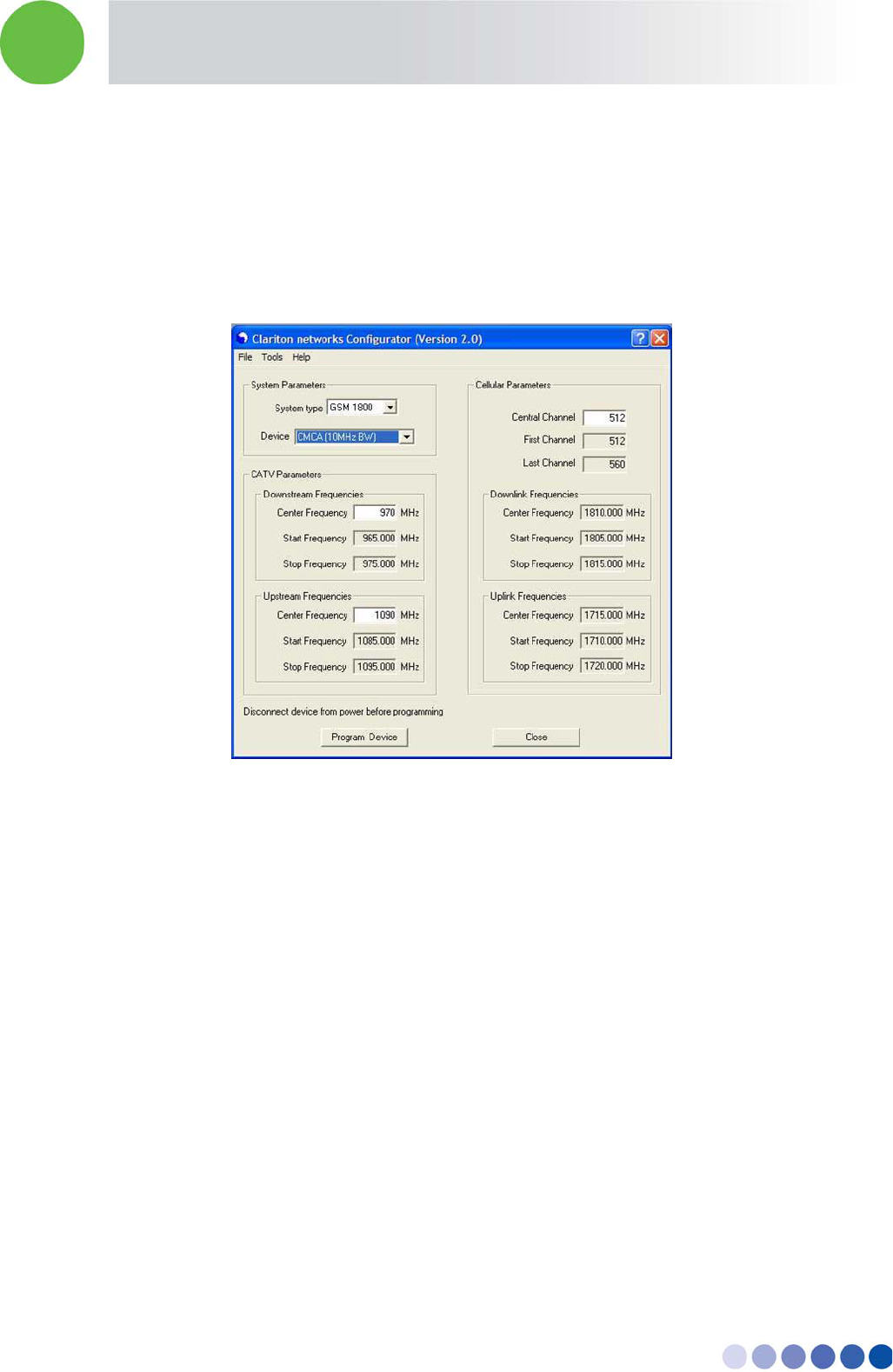
2. The configuration screen below will appear
Figure 17: Configuration Screen
3. The RS-232 green LED on the programmer will be turned on to indicate proper connectivity
4. Choose the technology and frequency band (i.e. UMTS, GSM 1800, etc)
5. Choose the device to be configured (UDC)
6. Cable band downstream - enter the center frequency (between 965 MHz to 1035 MHz)
7. Cable band upstream - enter the center frequency (between 1080 MHz to 1155 MHz)
8. Cellular band – enter the downlink band
(in GSM = central channel number, in UMTS = first downlink channel number, in PCS = Block, in
iDEN = center frequency in MHz)
9. Verify all inputs
Note:
Make sure the programmed device is DISCONNECTED from power
In case none of the parameters was changed a warning will be displayed before programming
takes place.
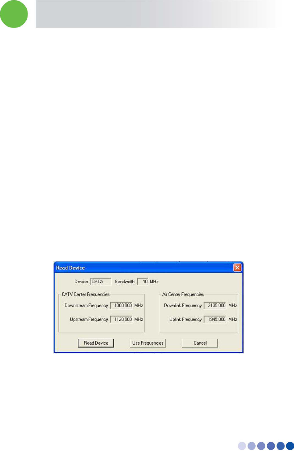
In-building Cellular Solution for Commercial Buildings UDC Software Configuration Tool
BreezeCELL 40
10. Press Program Device
11. The red VPP and VDD LEDs on the programmer will be turned on and a status window will be
displayed.
A.4. Tools
On the main menu press Tools
A.4.1. Recall Configuration from a Device
The configuration of a UDC can be recalled from a pre-configured device.
1. Connect the device to the programmer
2. Press the Read Device button
3. The red VPP and VDD LEDs on the programmer will be turned on and a status window will be
displayed.
4. The device parameters will be displayed in the Read Device window.
A.4.2. Use Device Configuration
The recalled parameters can be used to configure a new device
1. Press the Use Frequencies button.
2. The device parameters will be transferred to the main configuration template.
3. Verify all inputs
4. Press Program Device.
Figure 18: Tools Screen
A.5. Configuration Management
Configurations can be saved and restored from a database. Up to 1,000 different configurations can be
loaded and displayed using the File menu.
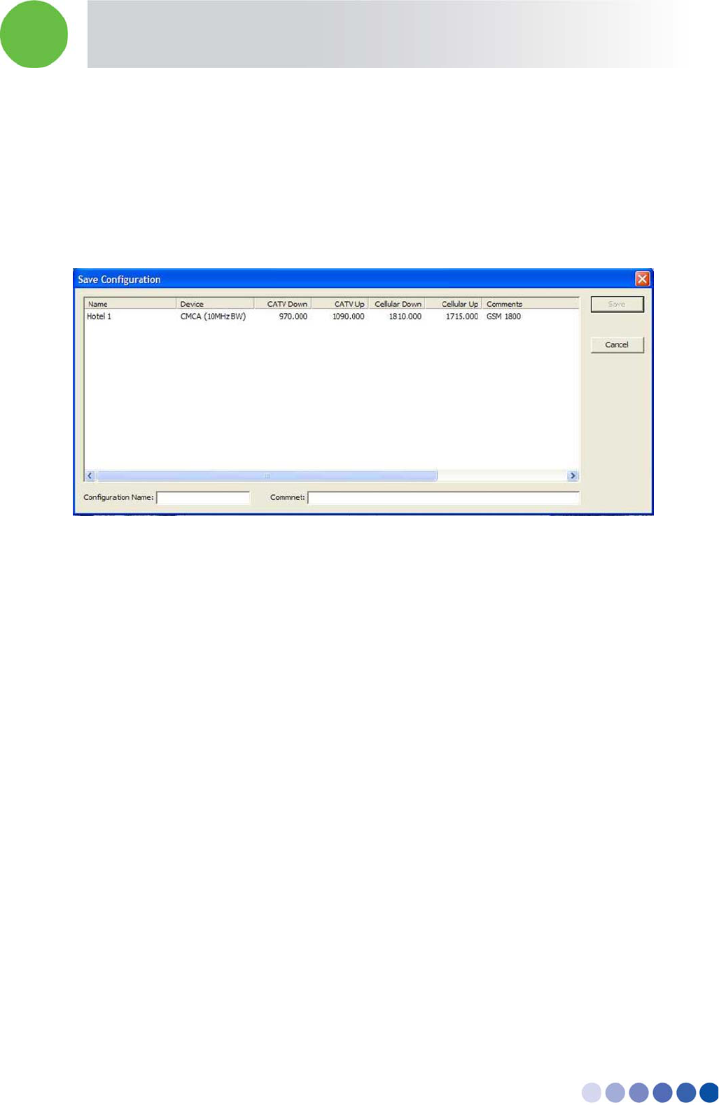
In-building Cellular Solution for Commercial Buildings UDC Software Configuration Tool
BreezeCELL 41
A.5.1. Saving a Configuration
You can save your current configuration in the following way:
1. Press File from top menu
2. Choose Save Configuration
3. Enter at the bottom the Configuration Name and Comment
4. Press the Save button
Figure 19: Save Configuration
A.5.2. Loading a Configuration
You can load past configurations from the database in the following way:
1. Press File from top menu
2. Choose Load Configuration
3. Click on the chosen configuration
4. Press the Load button
A.5.3. Deleting a Configuration
You can delete a configuration from the database in the following way:
1. Press File from top menu
2. Choose Delete Configuration
3. Click on the chosen configuration
4. Press the Delete button

In-building Cellular Solution for Commercial Buildings Power Ratings
BreezeCELL 42
Appendix B. Power Ratings
Device Input Voltage [Volts DC] Current [Amperes DC ]
UDC 9 1
CCD 110/230 Volts AC
(50/60Hz)
0.05 Amperes AC
Amplifier 7.5 0.3
Remote unit 5.7 2.7