Alvarion Technologies ERB-DS11 BreezeNET BU-DS.11 & RB-DS.11 User Manual
Alvarion Ltd. BreezeNET BU-DS.11 & RB-DS.11
Contents
- 1. 73 pages
- 2. revised user manual
revised user manual
BreezeNET DS.11 Series
BU-DS.11
RB-DS.11
User's
Guide
PRELIMINARYPRELIMINARY
July, 2000
Cat 12279903
Rev D

Front Matter
User’s Guide ii BreezeNET BU-DS.11/RB-DS.11
© 2000 by BreezeCOM Ltd. All rights reserved.
No part of this publication may be reproduced in any material form without the written permission
of the copyright owner.
No part of this publication may be reproduced in any material form without the written permission
of the copyright owner.
Trade Names
BreezeNET and BreezeLINK are trade names of BreezeCOM Ltd. Other brand and product names
are registered trademarks or trademarks of their respective companies.
Statement of Conditions
The information contained in this manual is subject to change without notice. BreezeCOM Ltd.
shall not be liable for errors contained herein or for incidental or consequential damages in
connection with the furnishing, performance, or use of this manual or equipment supplied with it.
Warranty
In the following warranty text, “the Company” shall mean:
- BreezeCOM Inc., for products located in the USA.
- BreezeCOM Ltd., for products located outside the USA.
This BreezeNET product is warranted against defects in material and workmanship for a period of
one year. During this warranty period the Company will, at its option, either repair or replace
products that prove to be defective.
For warranty service or repair, the product must be returned to a service facility designated by the
Company. Authorization to return products must be obtained prior to shipment. The buyer shall pay
all shipping charges to the Company and the Company shall pay shipping charges to return the
product to the buyer.
The Company warrants that the firmware designed by it for use with the unit will execute its
programming instructions when properly installed on the unit. The Company does not warrant that
the operation of the unit or firmware will be uninterrupted or error-free.
Limitation of Warranty
The foregoing warranty shall not apply to defects resulting from improper or inadequate
maintenance by the buyer, buyer supplied interfacing, unauthorized modification or misuse,
operation outside of the environmental specifications for the product, or improper site preparation

Front Matter
BreezeNET BU-DS.11/RB-DS.11 iii User's Guide
or maintenance. No other warranty is expressed or implied. The Company specifically disclaims
the implied warranties of merchantability and fitness for any particular purpose.
Electronic Emission Notices
This device complies with Part 15 of the FCC rules, ETSI 300-328, UL, UL/C, TUV/GS, and CE.
Operation is subject to the following two conditions:
1. This device may not cause harmful interference.
2. This device must accept any interference received, including interference that may cause
undesired operation.
FCC Radio Frequency Interference Statement
This equipment has been tested and found to comply with the limits for a Class B digital device,
pursuant to part 15 of the FCC Rules. These limits are designed to provide reasonable protection
against harmful interference in a residential installation. This equipment generates, uses and can
radiate radio frequency energy and, if not installed and used in accordance with the instructions,
may cause harmful interference to radio communications. However, there is no guarantee that
interference will not occur in a particular installation. If this equipment does cause harmful
interference to radio or television reception, which can be determined by turning the equipment off
and on, the user is encouraged to try to correct the interference by one or more of the following
measures:<O:P</O:P
•1 Reorient or relocate the receiving antenna.<O:P</O:P
•2 Increase the separation between the equipment and receiver.<O:P</O:P
•3 Connect the equipment into an outlet on a circuit different from that to which the receiver is
connected.<O:P</O:P
•4 Consult the dealer or an experienced radio/TV technician for help
Changes or modifications to this equipment not expressly approved by the party responsible for
compliance could void the user’s authority to operate the equipment.
FCC Radiation Exposure Statement
This equipment complies with FCC radiation exposure limits set forth for an uncontrolled
environment. This equipment should be installed and operated with the minimum distance between
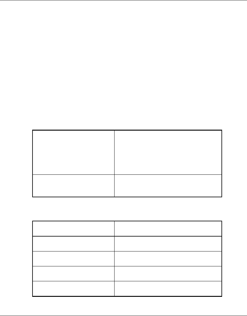
your body and the antenna, as shown in the table below:
High gain outdoor antennas (>8dBi) 30cm (12 inches)
Professional Installer (Antennas)
WARNING: It is the responsibility of the installer to insure that when using the outdoor

Front Matter
User’s Guide iv BreezeNET BU-DS.11/RB-DS.11
antenna kits in the United States (or where FCC rules apply), only those antennas
certified with the product are used. The use of any antenna other than those
certified with the product is expressly forbidden in accordance to FCC rules
CFR47 part 15.204.
The installer should configure the output power level of antennas, according to country regulations
and per antenna type.
Information to User
Any changes or modifications of equipment not expressly approved by the manufacturer could void
the user’s authority to operate the equipment and the company’s warranty.
Contacting BreezeCOM Technical Support
Should you need assistance beyond the scope of this guide, please contact your local BreezeCOM
reseller or distributor. If they cannot solve your problem, feel free to contact the BreezeCOM
Technical Support Department. The support representatives can assist you in solving any problems
that cannot be solved by your reseller.
When requesting support, please have the following items available:
•5 Configuration of the system, including models of the BreezeCOM equipment used.
•6 Antenna type and cable lengths.
•7 Site information such as possible radio path problems (like trees, machines, and buildings).
•8 Distance between devices.
•9 Configuration, statistic counters, and error messages as seen on the monitor.
•10 Description of problems encountered.
To contact BreezeCOM Technical Support, refer to the Technical Support page of the BreezeCOM
web site: www.breezecom.com

Table of Contents
BreezeNET BU-DS.11/RB-DS.11 v User's Guide
TABLE OF CONTENTS
1. INTRODUCTION............................................................................................................................... 1-1
1.1 General......................................................................................................................................1-1
1.2 System Description.................................................................................................................1-1
1.2.1 BreezeNET DS.11 Compatibility and Standards .......................................................1-1
1.3 BreezeNET DS.11 Functional Description...........................................................................1-2
1.4 How to Use This Guide ...........................................................................................................1-4
2. INSTALLATION ................................................................................................................................ 2-1
2.1 Quick Start to Wireless Networking......................................................................................2-1
2.2 Packing List..............................................................................................................................2-2
2.3 Other Items Required for Installation....................................................................................2-2
2.4 Installation Overview...............................................................................................................2-3
2.5 Guidelines for Placement of BU-DS.11 Units .....................................................................2-5
2.6 Outdoor Installation Considerations ......................................................................................2-6
2.6.1 Co-locating DS.11 Outdoor Units..............................................................................2-6
2.6.2 Site Selection Factors..................................................................................................2-6
2.6.3 Rooftop Installation.....................................................................................................2-8
2.6.4 Antennas for Outdoor Applications............................................................................2-8
2.6.5 Antenna Alignment.......................................................................................................2-9
2.6.6 Antenna Diversity.........................................................................................................2-9
2.6.7 Antenna Polarization................................................................................................. 2-10
2.6.8 Antenna Seal .............................................................................................................. 2-10
2.6.9 Cell Size..................................................................................................................... 2-10
2.6.10 Link Distance .......................................................................................................... 2-10
2.6.11 Using Outdoor Range Tables ................................................................................. 2-11

Table of Contents
User's Guide vi BreezeNET BU-DS.11/RB-DS.11
2.6.12 Available Antennas and Antenna Kits.................................................................... 2-11
2.6.13 Precautions.............................................................................................................. 2-13
2.6.14 Lightning Protection............................................................................................... 2-13
2.6.15 Rain Proofing.......................................................................................................... 2-14
2.7 Installing the Outdoor Unit .................................................................................................. 2-14
2.7.1 Connecting the Ground and Antenna Cables........................................................... 2-16
2.7.2 Connecting the Indoor-to-Outdoor Cable............................................................... 2-17
2.7.3 Verifying Correct Operation of the Outdoor Unit................................................. 2-18
2.8 Installing the Indoor Unit ..................................................................................................... 2-20
2.8.1 Verifying Correct Operation of the Indoor Unit.................................................... 2-22
2.8.2 Reloading Factory Default Settings......................................................................... 2-23
2.8.3 Connecting the Unit to the Ethernet Port ............................................................... 2-23
3. THE DS.11 MANAGEMENT UTILITY........................................................................................... 3-1
3.1 DS.11 Management Utility Main Window............................................................................3-2
3.1.1 Assigning and Editing IP Addresses Manually...........................................................3-3
3.1.2 Selecting Units.............................................................................................................3-3
3.1.3 IP/SNMP Tab................................................................................................................3-5
3.1.4 General Info Tab...........................................................................................................3-7
3.1.5 WLAN Parameters Tab................................................................................................3-8
3.1.6 RSSI Tab..................................................................................................................... 3-10
3.1.7 Counters Tab.............................................................................................................. 3-11
3.1.8 Station Control Tab................................................................................................... 3-12
3.1.9 Log Tab....................................................................................................................... 3-13
3.1.10 Security Tab............................................................................................................. 3-14
3.1.11 Debug Info(rmation)............................................................................................... 3-15
4. SYSTEM TROUBLESHOOTING..................................................................................................... 4-1
4.1 Troubleshooting Guide............................................................................................................4-1

Table of Contents
BreezeNET BU-DS.11/RB-DS.11 vii User's Guide
5. SOFTWARE DOWNLOAD PROCEDURE..................................................................................... 5-1
6. INSTALLING ACCESSORIES ......................................................................................................... 6-1
6.1 RFS 122 Radio Frequency Splitter.........................................................................................6-1
7. TECHNICAL SPECIFICATIONS..................................................................................................... 7-1
7.1 Supported Standards.................................................................................................................7-1
7.2 Power Specifications...............................................................................................................7-1
7.3 Wired LAN Interface...............................................................................................................7-1
7.4 Radio Specifications................................................................................................................7-2
7.5 Sensitivity.................................................................................................................................7-2
7.6 Configuration and Management..............................................................................................7-2
7.7 Specific Features .....................................................................................................................7-3
7.8 Size............................................................................................................................................7-3
7.9 Environmental ..........................................................................................................................7-3
APPENDIX A. RADIO SIGNAL PROPAGATION .................................................................................1
A.1 Radio Signal Propagation........................................................................................................... 1
A.1.1 Introduction..................................................................................................................... 1
A.1.2 RF Terms and Definitions.............................................................................................. 2
APPENDIX B. PREPARING THE INDOOR TO OUTDOOR CABLE.................................................1
APPENDIX C. DS.11 FAQ.........................................................................................................................1

Table of Contents
User's Guide viii BreezeNET BU-DS.11/RB-DS.11
TABLE OF FIGURES
Figure 1-1. DS.11 Outdoor Application......................................................................................1-2
Figure 2-1. General Installation Scheme - Pole Mounting........................................................2-4
Figure 2-2. Holes/Grooves/Screw Holes................................................................................. 2-14
Figure 2-3. Pole Mounting Installation Using the Supplied Brackets.................................... 2-15
Figure 2-4. Outdoor Radio Unit Bottom Panel ........................................................................ 2-16
Figure 2-5. Routing the Indoor-to-Outdoor Cable through the Waterproof Seal................. 2-17
Figure 2-6. Wall Mounting the Indoor Unit............................................................................. 2-20
Figure 2-7. Indoor Unit Rear Panel .......................................................................................... 2-21
Figure 2-8. Indoor Unit Front Panel......................................................................................... 2-21
Figure 3-1. DS.11 Management Utility Main Window (Station Control Tab).........................3-2
Figure 3-2. The Set IP Dialog Box...............................................................................................3-3
Figure 3-3. Signal Quality and RSSI Bar Display .......................................................................3-4
Figure 3-4. IP/SNMP Tab.............................................................................................................3-5
Figure 3-5. General Info Tab........................................................................................................3-7
Figure 3-6. WLAN Parameters Tab.............................................................................................3-8
Figure 3-7. RSSI Tab.................................................................................................................. 3-10
Figure 3-8. Counters Tab........................................................................................................... 3-11
Figure 3-9. The Station Control Tab......................................................................................... 3-12
Figure 3-10. Log Tab.................................................................................................................. 3-13
Figure 3-11. Security Tab.......................................................................................................... 3-14
Figure 7-1. Ethernet Connector Pin Assignments......................................................................... 1
Figure A-1. A Typical Radio System..........................................................................................A-1
Figure A-2. Attenuation of an RF signal.....................................................................................A-2
Figure A-3. Side View..................................................................................................................A-4
Figure A-4. Top View...................................................................................................................A-5
Figure A-5. Radiation Pattern of Directional Antenna..............................................................A-5
Figure A-6. Multipath Reception................................................................................................A-8
Figure A-7. Fresnel Zone.............................................................................................................A-9
Figure A-8. Fresnel Zone Clear of Obstacles..........................................................................A-10

Table of Contents
BreezeNET BU-DS.11/RB-DS.11 ix User's Guide
TABLE OF TABLES
Table 2-1. Regulatory Domains Specifications...........................................................................2-5
Table 2-2. FCC Available Antennas (USA) .............................................................................. 2-11
Table 2-3. ETSI Available Antennas (Europe and Rest-of-World) ........................................ 2-12
Table 2-4: Outdoor Unit LEDs................................................................................................... 2-18
Table 3-1. Frequency Selection List.............................................................................................3-9
Table 4-1. Troubleshooting ..........................................................................................................4-1

Introduction
BreezeNET BU-DS.11/RB-DS.11 1-1 User’s Guide
1. INTRODUCTION
1.1 General
This chapter describes the scope of this manual and the main features of the
BreezeNET BU-DS.11 (Wireless Base Station) and RB-DS.11 (Wireless Bridge
Client).
Also in this chapter: relevant standards, compatibility issues, product functionality and
use of the DS (Direct Sequence) WLAN.
1.2 System Description
The BreezeNET DS.11 Wireless Base Station and Wireless Bridge Client are designed
to provide long range point-to-multipoint links for outdoor applications. The products
use direct sequence, spread spectrum radio technology operating at a frequency of 2.4
– 2.4835 GHz, a part of the FCC's unlicensed Industrial, Science, Medical (ISM) band.
Data is transmitted at rates of up to 11 Mbps, providing network users with full
10BASE-T Ethernet speeds.
1.2.1 BreezeNET DS.11 Compatibility and Standards
BreezeNET DS.11 products are compatible with the following standards and are
interoperable with other IEEE 802.11 TGb-compatible, 2.4 GHz direct sequence
products.
•1 FCC 15.203
•2 IEEE 802.11 TGb Wireless LAN
•3 IEEE 802.3 10BASE-T Ethernet
•4 IEEE 802.1Q support for Virtual LAN
•5 DHCP for automatic IP address assignment
•6 SNMP for system management
Introduction
User's Guide 1-2 BreezeNET BU-DS.11/RB-DS.11
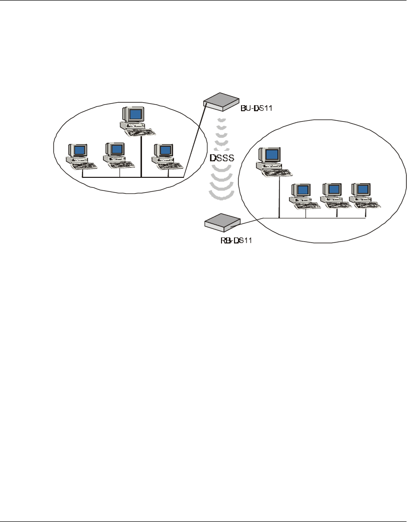
1.3 BreezeNET DS.11 Functional Description
The BreezeNET BU-DS.11 and RB-DS.11 can be used as a high speed connection
between two remote networks.
Server
Server
Figure 1-1. DS.11 Outdoor Application
BU-DS.11 Wireless Base Station
The BU-DS.11 is an IEEE 802.11 TGb-compliant base station bridge that is used to
connect either a single remote site or multiple remote sites to a central server or
Internet connection. It is the central unit for a multipoint configuration and always one
side of a point-to-point configuration.
The BU-DS.11 comes in two options: the basic unit comes with an antenna integrated
on the front cover of the Outdoor unit. In this model, the front cover also functions as
a protective sun cover.
In BU-DS.11D models with no integral antenna, the unit is provided with two antenna
connectors (on the Outdoor unit) for connection of one or two external antennas.
Refer to Section Sections 2.6.4 and 2.6.12 for information on how to select external
antennas. When two antennas are connected to the Outdoor unit, the unit supports the
antenna diversity feature described in Section 2.6.6.

Introduction
BreezeNET BU-DS.11/RB-DS.11 1-3 User’s Guide
RB-DS.11 Wireless Bridge Client
The RB-DS.11 connects a remote Ethernet network to a BU-DS.11 Multipoint Base
Station bridge located at a central server or Internet site. It can be programmed to
handle up to 1024 MAC addresses.
When a station on the Ethernet LAN sends a message that is not destined for a local
station, the RB-DS.11 wirelessly forwards the message to the BU-DS.11. When the
BU-DS.11 receives a message destined for a station on the RB-DS.11's LAN, the BU-
DS.11 wirelessly forwards it to the RB-DS.11. In this manner, the RB-DS.11 and the
BU-DS.11 work together like a standard network bridge.
The first time each station on the RB-DS.11’s LAN sends a message, the station’s
address is registered in the RB-DS.11 and the BU-DS.11. The RB-DS.11 and BU-
DS.11 can hold all the addresses necessary to support an entire LAN connected to a
RB-DS.11.
The RB-DS.11 comes in two options: the basic unit comes with an antenna integrated
on the front cover of the Outdoor unit.
The RB-DS.11D has no integral antenna, and provides two antenna connectors (on the
Outdoor unit) for connection of one or two external antennas. Refer to Section
Sections 2.6.4 and 2.6.12 for information on how to select external antennas. When
two antennas are connected to the Outdoor unit, the unit supports the antenna diversity
feature described in Section 2.6.6.

Introduction
User's Guide 1-4 BreezeNET BU-DS.11/RB-DS.11
1.4 How to Use This Guide
This User's Manual provides instructions for planning and setting up your Wireless
LAN. This includes details on how to install each unit, including antennas and
accessories.
This manual contains the following chapters:
⇒1 Chapter 1: Introduction - Explains how to use this manual and presents the
BreezeNET DS.11 series.
⇒2 Chapter 2: Installation - Describes how to install the units.
⇒3 Chapter 3: Using the DS.11 Management Utility - Describes how to use the DS.11
Management utility to setup, configure, and manage BreezeNET DS.11 series
units.
⇒4 Chapter 4: System Troubleshooting - Contains a troubleshooting guide for some of
the more common problems which may occur when installing and using the
BreezeNET DS.11 products.
⇒5 Chapter 5: Downloading Software Upgrades - Explains how to perform software
upgrades using a TFTP application.
⇒6 Chapter 6: Installing Accessories - Describes various accessories that can be
installed in specific situations.
⇒7 Chapter 7: Technical Specifications - Lists the technical specifications for the
BreezeNET DS.11 series units.
⇒8 Appendix A: Radio Signal Propagation - Explains many of the terms related with
antennas and RF (Radio Frequency) systems.
⇒9 Appendix B: DS.11 FAQ- Answers to customers Frequently Asked Questions.

Installation
BreezeNET BU-DS.11/RB-DS.11 2-1 User’s Guide
2. INSTALLATION
2.1 Quick Start to Wireless Networking
Perform the following steps to configure a WLAN for the first time:
1. Physically connect the BU-DS.11/RB-DS.11 units to the Ethernet LAN. Make
sure they are switched on. The DS.11 wireless network will be up and running
immediately. If you are content with the default settings of the BU-DS.11/RB-
DS.11 units, you can stop right here. It is more likely however, that you want to
assign different radio frequencies to each BU-DS.11/RB-DS.11, or impose some
restrictions on the use of your wireless network.
2. To be able to manage the BU-DS.11/RB-DS.11 units via SNMP, each BU-
DS.11/RB-DS.11 needs a unique IP address. If you provide a DHCP or BOOTP
service on your LAN (and have sufficient free IP addresses available) this will be
taken care of automatically. If not, refer to Section 3.1.1 for further information
on assigning IP addresses.
3. Use the BreezeNET DS.11 Management utility, described in Chapter 3 of this
manual, to configure the network settings to reflect your configuration.
4. Select the radio channels of the BU-DS.11/RB-DS.11 units according to your cell
plan. See Section 3.1.5 for further information. Add descriptive information about
each unit for later reference.

Installation
User's Guide 2-2 BreezeNET BU-DS.11/RB-DS.11
2.2 Packing List
When you first open the package, verify that the unit is complete with the following
components:
•1 Indoor unit
•2 Outdoor unit (includes integrated antenna or antenna connectors for optional
connection to external antennas)
•3 Pole mounting kit for the Outdoor unit (2 U-bolts that fit up to 2” poles)
•4 110/220 VAC Power Cord (may be open-ended, depending on destination
country)
2.3 Other Items Required for Installation
•1 Indoor-to-Outdoor cable* (available in different lengths)
•2 Antenna(s) and RF cable(s) if using an external antenna
•3 Power mains cable termination plug per country of installation (if the supplied
cable is open-ended)
•4 Ground cable with an appropriate termination
•5 Ethernet cable (straight)
•6 3 RJ-45 connectors; one of the RJ45 connectors, designated for connection to
the Indoor unit, is equipped with a plastic cover.
•7 Appropriate means for installing the Outdoor unit. A suitable pole and/or a wall
mounting kit* (if the unit is to be installed on a wall).
•8 Installation tools and materials
•9 Crimping tool
Items marked with an asterisk (*) are available as options from BreezeCOM.

Installation
BreezeNET BU-DS.11/RB-DS.11 2-3 User’s Guide
2.4 Installation Overview
Note: Outdoor units and antennas should be installed ONLY by experienced installation
professionals who are familiar with local building and safety codes and, wherever
applicable, are licensed by the appropriate government regulatory authorities.
Failure to do so may void the BreezeCOM product warranty and may expose the
end user or the service provider to legal and financial liabilities. BreezeCOM and
its resellers or distributors are not liable for injury, damage or violation of
regulations associated with the installation of outdoor units or antennas.
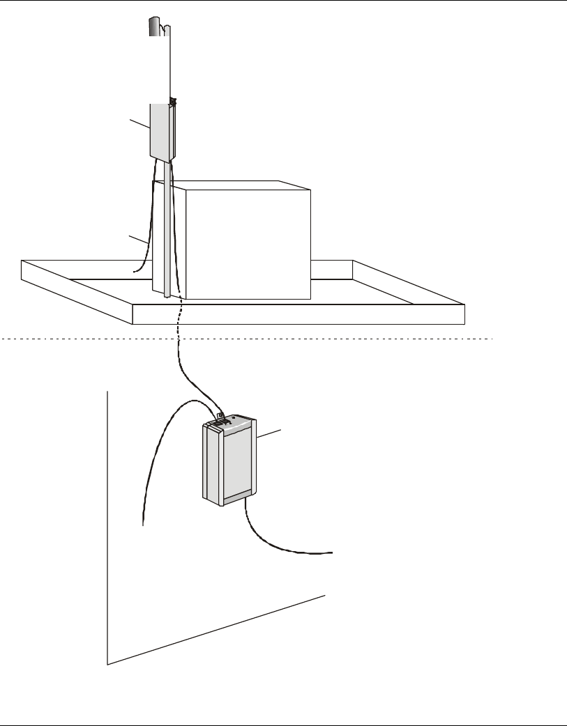
The typical installation scheme is depicted in Figure 2-1. The installation process
should follow these general steps:
1. Select appropriate locations for the Outdoor unit, the antenna (if using an optional
external antenna) and the Indoor unit.
2. Mount the Outdoor unit and the external antennas (optional). Connect the Outdoor
unit to the antenna if installing external antennas.
Note: The FCC 15.203 requirement prohibits the connection of external antennas with
standard N-type connectors. In order to meet this requirement, the external
antenna connectors provided on DS.11D models (with no integral antenna) are
non-standard, featuring left-handed (counter-clockwise) rotation.
3. Connect a ground cable between the Outdoor unit and an appropriate grounding
point.
4. Connect the Indoor-to-Outdoor cable to the Outdoor unit and route it to the
location selected for the Indoor unit. Assemble the enclosed connector on the
cable. Refer to Appendix B for instructions on preparing the Indoor-to-Outdoor
cable.
5. Mount the Indoor unit. Connect the Indoor-to-Outdoor cable to the Indoor unit
Radio port. Prepare the power cable and use it to connect the Indoor unit to the
AC mains.
6. Connect the Indoor unit Ethernet port to the user’s network/PC using an Ethernet
cable.
7. Align the antenna and verify connectivity with the Base Station.
Note: The Indoor unit should be connected to the power source only after it has been
connected to the Outdoor unit.
Installation
User's Guide 2-4 BreezeNET BU-DS.11/RB-DS.11
Antenna
(BU-DS11D
and
RD-DS11D units
only)
Outdoor Unit
Indoor Unit
Ground Cable
to Grounding Point
To Mains
To LAN
Indoor to Outdoor
Unit Cable
ANT 1
OUTDOOR
INDOOR
Figure 2-1. General Installation Scheme - Pole Mounting
Antenna
(BU-DS.11D and
RB-DS.11D units only)

Installation
BreezeNET BU-DS.11/RB-DS.11 2-5 User’s Guide
2.5 Guidelines for Placement of BU-DS.11 Units
Each Wireless Base Station in the network forms the center of a cell, or BSS. The
placement of BU-DS.11 units should be such that cells overlap slightly, to guarantee
seamless wireless connectivity everywhere. Neighboring BU-DS.11 units should
preferably send and receive on different channels for maximum throughput.
Creating a cell plan for your site can be complicated, and is usually done by experts
equipped with special measuring equipment.
Furthermore, the radio channels you may use depend on both the capabilities of the
PC-cards you are deploying, as well as the regulations in your area. Table 2-1 provides
specifications for the main regulatory domains:
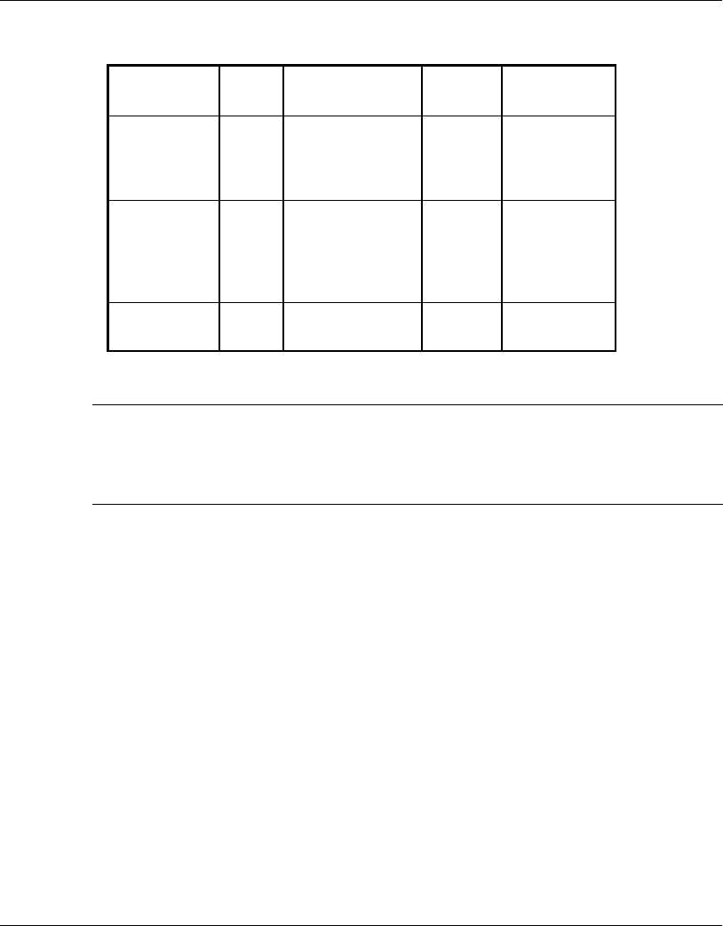
Table 2-1. Regulatory Domains Specifications
Regulatory
Domain Region Permissible
Channels Predefined
Channels
FCC United States 1 - 11 1, 6, 11
DOC Canada 1 - 11 1, 6, 11
ETSI Europe except
Spain and France 1 - 13 1, 7, 13
SPAIN Spain 10 10
FRANCE France 10 10
MKK Japan 1-14 1-14

Installation
User's Guide 2-6 BreezeNET BU-DS.11/RB-DS.11
2.6 Outdoor Installation Considerations
This chapter describes various considerations to take into account when planning an
outdoor installation including site selection, antenna alignment, antenna polarization,
antenna seal, and cell size.
2.6.1 Co-locating DS.11 Outdoor Units
Up to 3 BU-DS.11 or RB-DS.11 units can be co-located on the same building top or
tower. Each unit is assigned to one of the non-overlapping channels, 1, 6, or 11.
When co-locating outdoor units on the same building top or tower, the antennas
should be mounted at least 2 feet apart when using UNI-16’s, 15 feet when using UNI-
24’s, and 75 feet when using OMNI-8’s. For omni antennas, the maximum link
distance is reduced by up to 50%. Greater separation will improve the link distance.
2.6.2 Site Selection Factors
When selecting a location for external antennas, remember to take into consideration
the following guidelines:
•1 Minimum distance between sites
•2 Maximum height above the ground
•3 Maximum line of sight clearance
Path of Clearest Propagation
A propagation path is the path that signals traverse between the antennas of any two
bridges. The “line” between two antenna sites is an imaginary straight line, which may
be drawn between the two antennas. Any obstacles in the path of the “line” degrade the
propagation path. The best propagation path is, therefore, a clear line of sight with
good clearance between the “line” and any physical obstacle.

Installation
BreezeNET BU-DS.11/RB-DS.11 2-7 User’s Guide
Physical Obstacles
Any physical object in the path between two bridges can cause signal attenuation.
Common obstructions are buildings and trees. Any buildings or other physical
structure such as trees, mountains or other natural geographic features higher than the
antenna and situated in the path between the two sites can constitute obstructions.
Install outdoor antennas high enough to avoid any obstacles, which may block the
signal.
Minimal Path Loss
Path loss is determined mainly by several factors:
•4 Distance between sites – Path loss is lower and system performance better when
distances between sites are shorter.
•5 Clearance – Path loss is minimized when there exists a clear line of sight. The
number, location, size, and makeup of obstacles determine their contribution to
path loss.
•6 Antenna height – Path loss is lower when antennas are positioned higher. Antenna
height is the distance from the imaginary line connecting the antennas at the two
sites to “ground” level. “Ground” level in an open area is the actual ground. In
dense urban areas, “ground” level is the average height of the buildings between
the antenna sites.

Installation
User's Guide 2-8 BreezeNET BU-DS.11/RB-DS.11
2.6.3 Rooftop Installation
WARNING! Rooftop antenna installations are extremely dangerous! Incorrect
installation may result in death, serious injury and/or damage. Such
installations should be performed by professional antenna installers
only!
Rooftop installations offer several advantages:
•1 Increased antenna range.
•2 Fewer obstacles in path.
•3 Improved performance due to greater height.
•4 Reduced multipath problems.
2.6.4 Antennas for Outdoor Applications
The BreezeNET DS.11 series can be used in point-to-point or point-to-multipoint
configurations.
Point-to-Point
The BU-DS.11/RB-DS.11 must be equipped with one or two directional antennas. The
necessary antenna gain depends on the required range and performance.
Point-to-Multipoint
Setting up a point-to-multipoint link requires the use of a BU-DS.11 equipped with
omni-directional antennas and at least two RB-DS.11 units equipped with high-gain
directional antennas.
Note: The FCC 15.203 requirement prohibits the connection of external antennas with
standard N-type connectors. In order to meet this requirement, the external
antenna connectors provided on DS.11D models (with no integral antenna) are
non-standard, featuring left-handed (counter-clockwise) rotation.

Installation
BreezeNET BU-DS.11/RB-DS.11 2-9 User’s Guide
2.6.5 Antenna Alignment
Low gain antennas do not require alignment due to their very wide radiation pattern.
High gain antennas have a narrow beamwidth necessitating an alignment procedure in
order to optimize the link.
Check antenna alignment by using the RSSI bar on the bottom panel of the
RB-DS.11 bottom panel.
⇒1⇒1 To perform antenna alignment:
1. Assemble antennas according to the assembly instructions included with the
antenna set.
2. Mount the antennas as high as possible.
3. Connect the coaxial cable to the BU-DS.11 at the main site.
4. Connect the coaxial cable to the RB-DS.11 at the remote site.
5. Power on both units.
6. Synchronize the units by aligning the antennas at the main and remote sites until
maximum signal quality is obtained. Check the signal quality RSSI bar on the
bottom panel of the RB-DS.11 bottom panel. If the received signal quality is lower
than expected for this antenna/range combination, change antenna height and verify
RF cables connections.
2.6.6 Antenna Diversity
In applications where no multipath propagation is expected, a single antenna is
sufficient for good performance levels. However, in cases where multipath
propagation exists BreezeCOM recommends using two antennas in order to utilize the
space diversity feature. By using two antennas per unit, the system can select the best
antenna on a per-packet basis (every several milliseconds).
Multipath propagation is to be expected when there are potential reflectors between
the main and remote sites. These reflectors may be buildings or moving objects such
as airplanes and motor vehicles. If this is the case, the radio signal does not travel in a
straight line, but is reflected or deflected off of the object, creating multiple
propagation paths.

Installation
User's Guide 2-10 BreezeNET BU-DS.11/RB-DS.11
When installing a single antenna, modify the transmit diversity option to either antenna
1 or antenna 2, according to the antenna being used (refer to page 3-9).
2.6.7 Antenna Polarization
Antenna polarization must be the same at either end of the link. In most applications,
the preferred orientation is vertical polarization. Above-ground propagation of the
signal is better when it is polarized vertically. To verify antenna polarization, refer to
the assembly instructions supplied with the antenna set.
2.6.8 Antenna Seal
When using outdoor antennas, you must seal unused antenna connectors against rain
with the antenna connector seals provided with the unit.
2.6.9 Cell Size
Cell size is determined by the maximum possible distance between the BU-DS.11 and
the RB-DS.11 unit, usually related to point-to-multipoint installations using external
antennas. For open outdoor areas with an unobstructed line of sight between the BU-
DS.11 and the RB-DS.11 units, the suggested maximum distance is up to 7KM (4.3
miles).
2.6.10 Link Distance
For open outdoor areas with an unobstructed line of sight between the BU-DS.11 and
the wireless bridge, the suggested maximum distance is:
BU-DS.11 with external antennas up to
24Km (15 miles) in the USA Up to 15Km in Europe
Note: The maximum distance of 24Km/15 miles is achieved using 24 dBi antennas.
The maximum distance of 15Km is achieved using 18 dBi antennas.

Installation
BreezeNET BU-DS.11/RB-DS.11 2-11 User’s Guide
2.6.11 Using Outdoor Range Tables
Outdoor installations must have a clear line-of-sight. Solid obstacles such as buildings
or hills prevent the establishment of a link. Partial obstacles such as trees or traffic
can reduce range. Extending coaxial cables can cause an increase in assembly signal
loss and a reduction in range.
Specific range tables, guidelines and information about extending cables can be
obtained from your local dealer or the BreezeCOM central offices.
2.6.12 Available Antennas and Antenna Kits
Table 2-2 and Table 2-3 list several transmit/receive antennas that work well with
BreezeNET DS.11 units. Antenna types that passed the regulation phase for both ETSI
and FCC are indicated in bold type.
The cable length should be minimized in order to gain max link budget.
Table 2-2. FCC Available Antennas (USA)
Model Ant.
Gain Ideal for: Dispersio
n Dimensions
H x W x D
OMNI-8 8 dBi Establishing 360°
coverage for
outdoor multipoint
links
360°H/
22° V
16"x0.75"
Tubular
UNI-16P 16 dBi Medium to long
range outdoor
multipoint links
requiring compact
form factors
28°H/
28° V
11"x11"x3.5"
UNI-24 24 dBi Long range outdoor
point-to-point links
6°H/
10° V
24"x36"x15"
* Antenna types that passed the regulation phase for both ETSI and FCC are indicated in bold type.
Installation
User's Guide 2-12 BreezeNET BU-DS.11/RB-DS.11
Table 2-3. ETSI Available Antennas (Europe and Rest-of-World)
Model Ant.
Gain Ideal for: Dispersio
n Dimensions
H x W x D
OMNI-8 8 dBi Establishing 360°
coverage for
outdoor multipoint
links
360°H/
22° V
16"x0.75"
Tubular
UNI-16P 16 dBi Medium to long
range outdoor
multipoint links
requiring compact
form factors
28°H/
28° V
11"x11"x3.5"
UNI-24 24 dBi Long range outdoor
point-to-point links
6°H/
10° V
24"x36"x15"
Note: The FCC 15.203 requirement prohibits the connection of external antennas with
standard N-type connectors. In order to meet this requirement, the external
antenna connectors provided on DS.11D models (with no integral antenna) are
non-standard, featuring left-handed (counter-clockwise) rotation.

Installation
BreezeNET BU-DS.11/RB-DS.11 2-13 User’s Guide
2.6.13 Precautions
Note: Detached antennas, whether installed indoors or out, should be installed ONLY by
experienced antenna installation professionals who are familiar with local building
and safety codes and, wherever applicable, are licensed by the appropriate
government regulatory authorities.
Failure to do so may void the BreezeNET Product Warranty and may expose the
end user to legal and financial liabilities. BreezeCOM and its resellers or
distributors are not liable for injury, damage or violation of government
regulations associated with the installation of detached antennas.
Transmit Antenna
Regulations regarding maximum antenna gains vary from country to country. It is the
responsibility of the end user to operate within the limits of these regulations and to
ensure that the professional installer is aware of these regulations, as well.
Violation of government regulations exposes the end user to legal and financial
liabilities. BreezeCOM, its resellers and distributors shall not be liable for expense or
damage incurred as a result of installations which exceed local transmit gain
limitations.
2.6.14 Lightning Protection
Lightning protection is designed to protect people, property and equipment by
providing a path to ground for the lightning’s energy. The lightning arrestor diverts the
strike energy to ground through a deliberate and controlled path instead of allowing it
to choose a random path. Lightning protection for a building is more forgiving than
protection of electronic devices. A building can withstand up to 100,000 volts, but
electronic equipment may be damaged by just a few volts.
The Outdoor unit contains an internal lightning protection unit, and should be installed
and grounded at the point where the cable enters the building.
Installation
User's Guide 2-14 BreezeNET BU-DS.11/RB-DS.11
2.6.15 Rain Proofing
18 and 24 dBi antennas must be sealed against rain at the point the cable enters the
pole before they are suitable for external use.
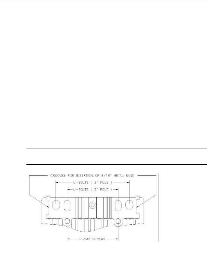
2.7 Installing the Outdoor Unit
The outdoor unit can be secured to the pole using one of the following options:
•1 Special brackets (supplied with each unit)
•2 U-bolts - size A (inner installation holes, up to 2" pole)
•3 U-bolt - size B (outside installation holes, up to 3" pole)
•4 Metal bands (9/16” wide, minimum 12” long)
Figure 2-2 shows the locations of the holes, grooves and screw holes on the rear side
of the unit.
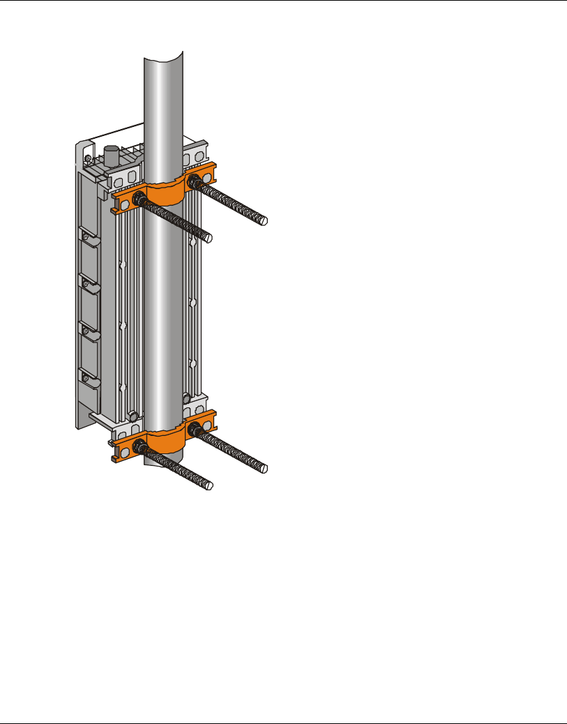
Figure 2-3 illustrates the method of installing an unit on a pole using the supplied
brackets.
Note: Make sure to install the unit with the bottom panel (the panel with the signal
strength bar and LEDs) facing downward.
Figure 2-2. Holes/Grooves/Screw Holes
Installation
BreezeNET BU-DS.11/RB-DS.11 2-15 User’s Guide
Figure 2-3. Pole Mounting Installation Using the Supplied Brackets
Installation
User's Guide 2-16 BreezeNET BU-DS.11/RB-DS.11
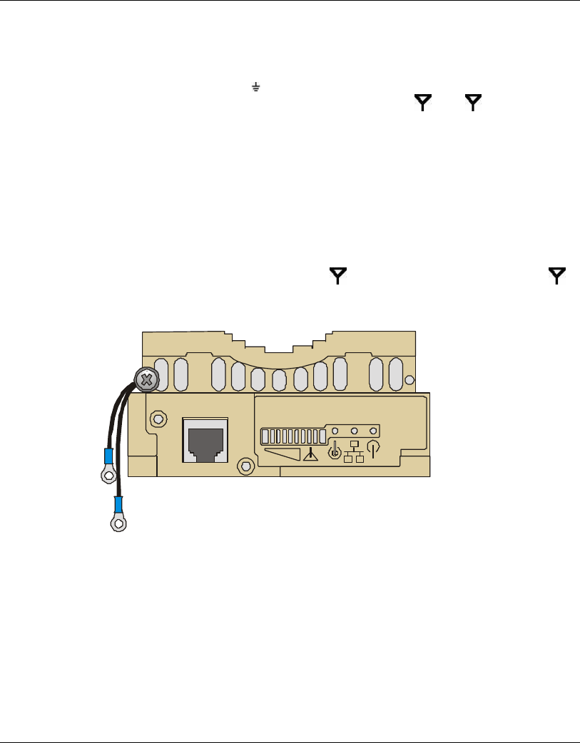
2.7.1 Connecting the Ground and Antenna Cables
The Ground terminal (marked is located on the bottom panel of the Outdoor unit,
shown in Figure 2-4. The Antenna RF connectors (marked 1 and 2 respectively)
are located on the top panel of the Outdoor unit.
1. Connect one end of the grounding cable to the Ground terminal and connect the
other end to a good ground connection.
2. Connect an RF cable between each ANT connector and the antenna. When
connecting two antennas, the Antenna Diversity feature described in Section 2.6.6
is supported.
When connecting only one antenna, use the 1 connector; make sure to seal the 2
connector using the waterproof seal provided with the unit.
Figure 2-4. Outdoor Radio Unit Bottom Panel
Installation
BreezeNET BU-DS.11/RB-DS.11 2-17 User’s Guide
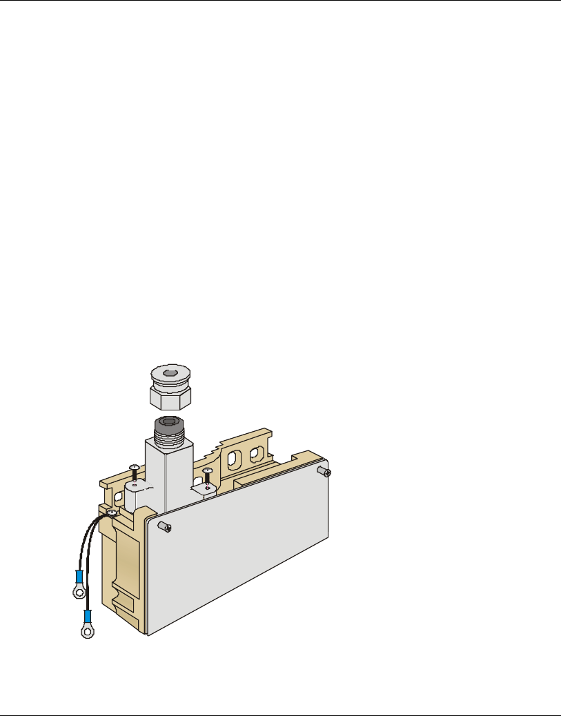
2.7.2 Connecting the Indoor-to-Outdoor Cable
1. Remove the two screws holding the waterproof seal assembly to the Outdoor unit
and remove the waterproof seal.
2. Unscrew the top nut from the waterproof seal.
3. Route an uncrimped straight Ethernet cable (8-wire, 24 AWG pin-to-pin) through
the top nut and the waterproof seal. Refer to Appendix B for instructions on
preparing the RJ-45 cable connector.
Note: The 8-wire cable should be shielded.
1. Insert and crimp the RJ45 connector.
2. Connect the Ethernet cable to the Outdoor unit Ethernet connector.
3. Replace the waterproof seal assembly to the Outdoor unit and then replace the top
nut.
Figure 2-5. Routing the Indoor-to-Outdoor Cable through the Waterproof Seal

Installation
User's Guide 2-18 BreezeNET BU-DS.11/RB-DS.11
2.7.3 Verifying Correct Operation of the Outdoor Unit
To verify proper operation, view the LED indicators located on the bottom panel of
the outdoor unit as shown in Figure 2-4.
Table 2-4 lists the various LED states.
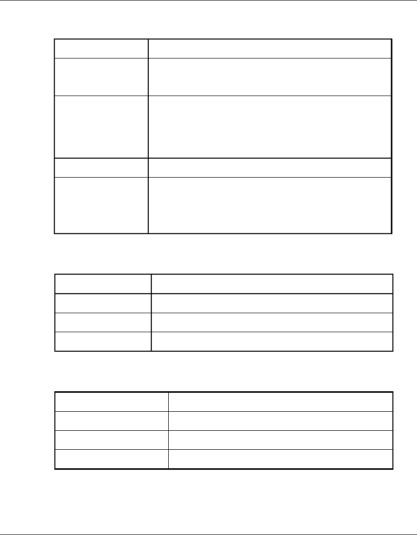
Table 2-4: Outdoor Unit LEDs
Name Description Functionality
WLAN Wireless Link Blinking Green – Data received or transmitted
on wireless link
Green –No data on link
DC Power Self Test and
Power indication Green – Self test passed and 12VDC power is
supplied to the unit
Red – Self test failed and 12VDC is not
available
ETH Ethernet activity Green –Ethernet link is operational, with no
traffic on the port.
Blinking Green –Ethernet link is operational,
with traffic on the port.
Red – No Ethernet link.

Installation
BreezeNET BU-DS.11/RB-DS.11 2-19 User’s Guide
Name Description Functionality
RSSI Bar
on
RB-DS.11
units
Series of LEDs Displays the RSSI (Received Signal Strength
Indication, or the received RF signal level) at the
Outdoor radio unit, as follows:
Bar0 (red) -91dBm
Bar1 (green) -87dBm
Bar2 (green) -83dBm
Bar3 (green) -80dBm
Bar4 (green) -77dBm
Bar5 (green) -74dBm
Bar6 (green) -71dBm
Bar7 (green) -66dBm
Bar8 (green) -61dBm
Bar9 (yellow) -55dBm
RSSI Bar
on
BU-DS.11
units
Series of LEDs Indicates the number of RB-DS.11 units
associated with the BU-DS.11; for each LED
that lights up, one RB-DS.11 is associated.
Bar0 (red) 1
Bar1 (green) 2
Bar2 (green) 3
Bar3 (green) 4
Bar4 (green) 5
Bar5 (green) 6-7
Bar6 (green) 8-15
Bar7 (green) 16-31
Bar8 (green) 32-63
Bar9 (yellow) 64-128
Installation
User's Guide 2-20 BreezeNET BU-DS.11/RB-DS.11
2.8 Installing the Indoor Unit
According to the specific conditions of the installation, route the Indoor-to-Outdoor
cable into the building so that it conveniently reaches the Indoor unit to ensure
minimal interference, leaving some spare. The cable is supplied open ended at the side
of the Indoor unit, to allow for conveniently threading it into the building through a
hole that is as small as possible. Assemble the connector and cover plug supplied with
the cable. Appendix B provides instructions on how to assemble the connector on the
Indoor-to-Outdoor cable.
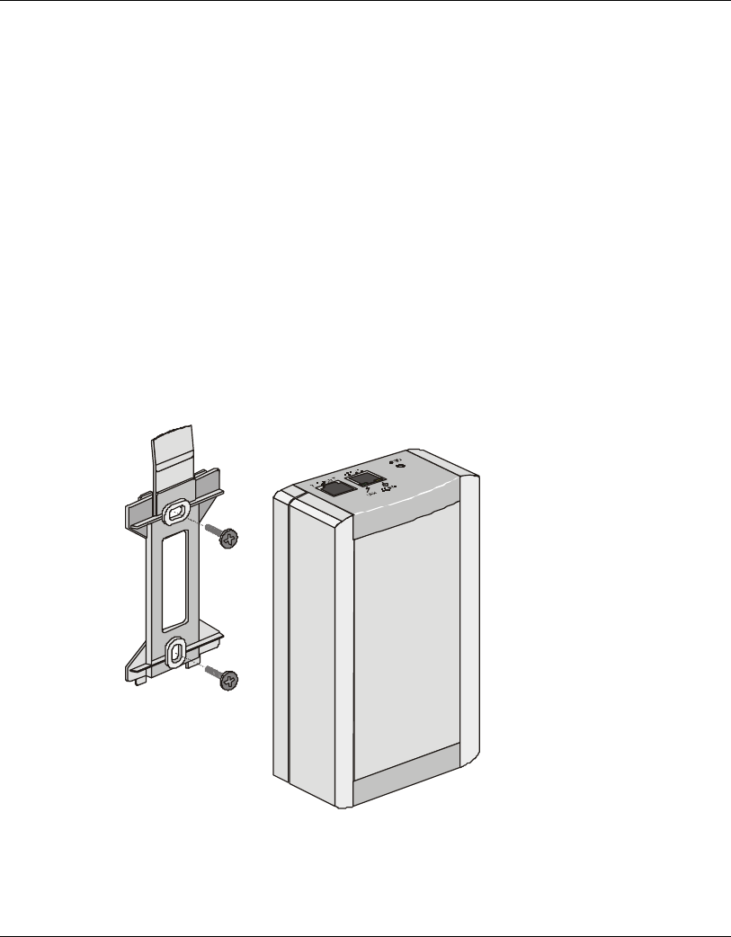
1. Remove the wall mounting bracket clipped to the rear of the Indoor unit and
mount the Indoor unit on a wall as shown in Figure 2-6.
2. Connect the Indoor-to-Outdoor cable to the Radio connector, located on the front
panel of the Indoor unit shown in Figure 2-8. The Indoor-to-Outdoor cable should
be connected to the unit before it is connected to the mains power.
Figure 2-6. Wall Mounting the Indoor Unit
Installation
BreezeNET BU-DS.11/RB-DS.11 2-21 User’s Guide
Note: If the power cord supplied with the unit is open ended, connect to it a power plug
appropriate to the country in which the unit is being installed. The color codes of
the cable are:
brown phase ~
blue neutral 0
yellow/green grounding
The operating AC mains voltage of the Indoor unit is marked on the rear panel of the
unit.
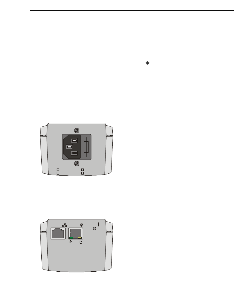
3. After connecting the Outdoor unit to the Indoor unit using the Indoor-to-Outdoor
cable, connect the power cord to the unit’s AC outlet, located on the rear panel
shown in Figure 2-7. Connect the other end of the power cord to the AC mains.
100-120VAC
207-253VAC 250mA
500mA
Figure 2-7. Indoor Unit Rear Panel
4. Verify that the POWER LED located on the rear panel lights Green, indicating
that the unit self-test passed and that 48 VDC output to the Outdoor unit is not
shorted.
10-BASE-T RADIO
RESET
LINK POWER
Figure 2-8. Indoor Unit Front Panel

Installation
User's Guide 2-22 BreezeNET BU-DS.11/RB-DS.11
5. Connect the 10-BASE-T connector to the network. The cable connection should
be straight.
Note: The length of the Ethernet cable connecting the Indoor unit to the user's
equipment, together with the length of the Indoor-to-Outdoor cable, should
not exceed 100 meters.
2.8.1 Verifying Correct Operation of the Indoor Unit
To verify proper operation, view the LED indicators located on the rear panel of the
outdoor unit as shown in Figure 2-8, and as described in Table 2-5.
Table 2-5. Indoor Unit LEDs
Name Description Functionality
POWER Power indication Lights Green when the Indoor unit supplies
48VDC to the Outdoor unit; OFF when no power
is supplied.
LINK Self Test and
Remote Ethernet
Link indication
OFF - Self test failed and no Ethernet link.
Green – Self test passed and remote Ethernet
link is OK.
Blinking Green – Self test passed
(instantaneously blinks when the baseband cable
is connected, regadless of the Ethernet link
status).

Installation
BreezeNET BU-DS.11/RB-DS.11 2-23 User’s Guide
2.8.2 Reloading Factory Default Settings
The Reset button, located on the Indoor unit front panel, is used to restore the factory
default parameter settings of the Outdoor unit (in the event that the default settings
were changed via an SNMP management station).
To reset the unit:
1. Disconnect the power cable from the Indoor unit.
2. Insert a paper clip and press the Reset button while inserting the power cable back
into its socket at the same time.
2.8.3 Connecting the Unit to the Ethernet Port
•1 Connect one end of a an Ethernet 10BaseT cable (not supplied) to the RJ-45 port
on the front panel of the Indoor unit, using a straight cable.
•2 Connect the other end of the connector cable to the Ethernet outlet.

The DS.11 Management Utility
BreezeNET BU-DS.11/RB-DS.11 3-1 User’s Guide
3. THE DS.11 MANAGEMENT UTILITY
The DS.11 Management utility is an SNMP-based (Simple Network Management
Protocol) utility that provides a consistent view of the wireless network. The system
administrator can use the DS.11 Management utility to control a large number of
DS.11 units from a single location. The management utility can be used to manage the
following DS.11 units: BU-DS.11 and RB-DS.11
Among the supported features:
•1 Assign radio channels for optimal cell management
•2 Program units with a specified IP address
•3 Set the SNMP Read/Write Community strings
•4 Verify the status of all units in the network
•5 Perform a site survey
•6 Antenna selection and diversity
•7 Configuration of parameters
•8 View the counters
•9 Set the antenna diversity
•10 Obtain general information
The DS.11 Management Utility
User's Guide 3-2 BreezeNET BU-DS.11/RB-DS.11
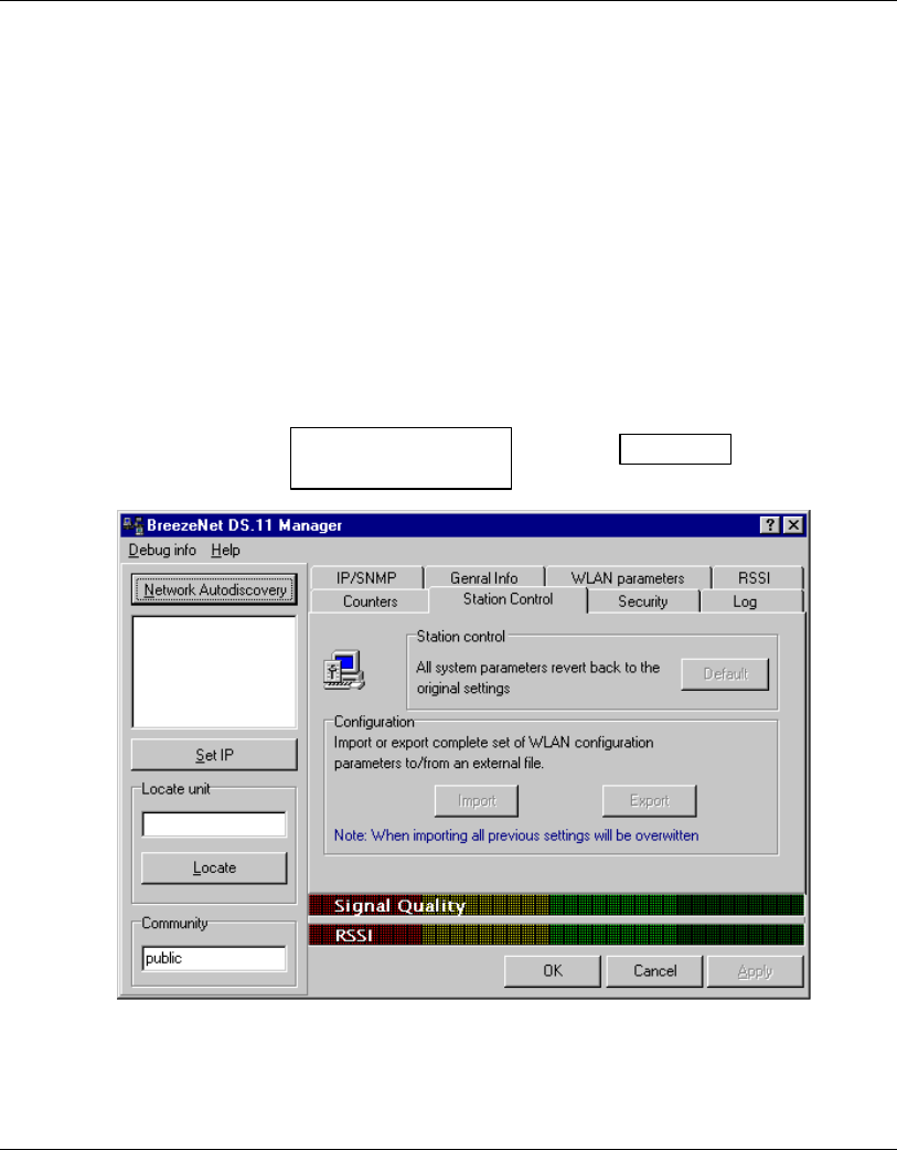
3.1 DS.11 Management Utility Main Window
The DS.11 Management utility main window consists of two main areas, as can be
seen in Figure 3-1:
•1 The IP Address and Community Selection area - In this area, you select the
community string and address of the unit you wish to manage or edit.
•2 The Tabs area - This area consists of several tabs, each corresponding to a dialog
box containing parameters required for the management of the selected unit; the
number of tabs displayed varies between the type of managed unit. The different
tabs are described in the following sections. When you switch between the tabs,
the IP Selection area with the selected unit address remains displayed.
Figure 3-1. DS.11 Management Utility Main Window (Station Control Tab)
The DS.11 Management utility main window contains the following buttons:
IP address and
Community selection
area
Tabs area
The DS.11 Management Utility
BreezeNET BU-DS.11/RB-DS.11 3-3 User’s Guide
•3 – Implements any changes you made and closes the window.
•4 – Closes the window without implementing any changes you made.
•5 – Implements any changes you made but leaves the window open.
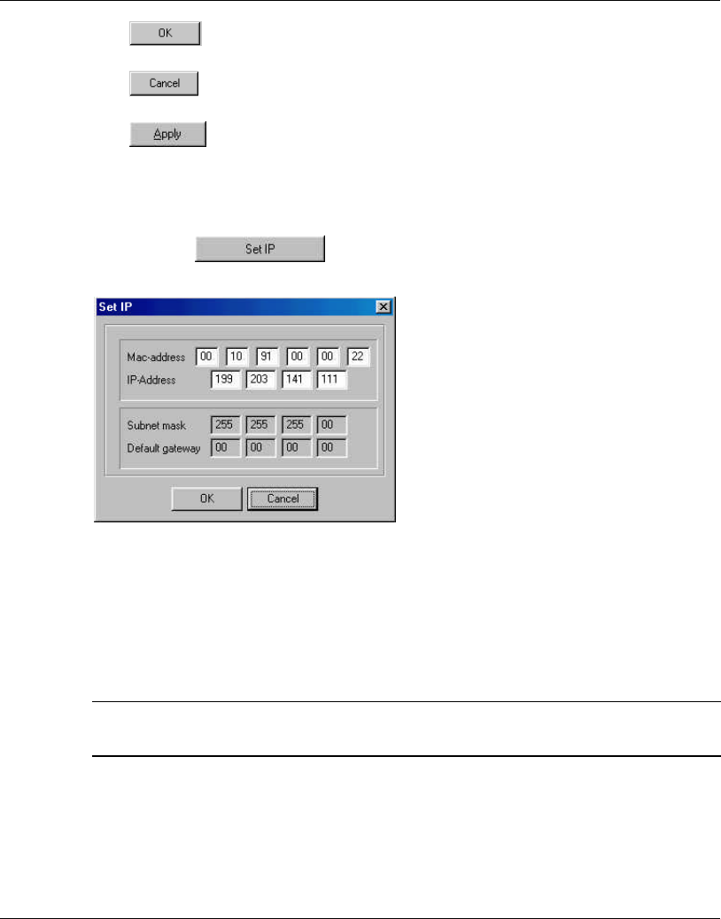
3.1.1 Assigning and Editing IP Addresses Manually
1. Click the button. The Set IP dialog box is displayed.
Figure 3-2. The Set IP Dialog Box
2. Type the parameters in the appropriate fields and click OK; the MAC address is
written underneath the unit. A message box is displayed notifying you when the
changes are to take affect. This feature can be used only if the Manager is on the
same Ethernet segment as the unit and not behind the router.
Note: In order to see the unit after assigning the IP address, the PC with the Manager
should be on the same IP subnet as the assigned DS.11 IP address.
3.1.2 Selecting Units
You can select a unit to manage in one of the following ways:
The DS.11 Management Utility
User's Guide 3-4 BreezeNET BU-DS.11/RB-DS.11
•1 Click the button. All the current units IP addresses (under the
selected community) are displayed in the list box underneath the button. Double-
click on an address to select it. The default read community is public and the
write is private.
•2 For stations which are located behind a router, type the unit's address in the
Locate unit field and click to display its parameters.
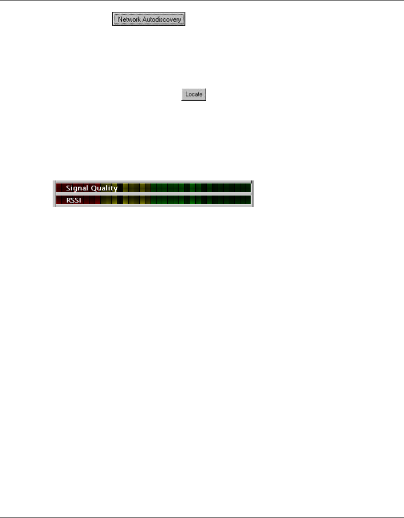
•3 Signal Quality and RSSI bars - These bars appears only if the selected IP address
is an RB-DS.11. The Signal Quality bar displays the signal quality between the
selected client and the BU-DS.11 connected to it. The RSSI bar displays the
signal strength.
Figure 3-3. Signal Quality and RSSI Bar Display
The DS.11 Management Utility
BreezeNET BU-DS.11/RB-DS.11 3-5 User’s Guide
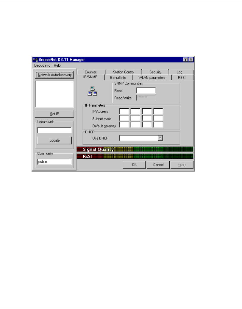
3.1.3 IP/SNMP Tab
Software upgrades can be downloaded to DS.11 units using the TFTP protocol.
The IP/SNMP tab allows you to define or edit the IP parameters for the DS.11 units,
used for the download procedure.
Figure 3-4. IP/SNMP Tab

The DS.11 Management Utility
User's Guide 3-6 BreezeNET BU-DS.11/RB-DS.11
3.1.3.1 Assigning and Editing IP Parameters Using Network
Autodiscovery
Type the known Read/Write Community string in the Community field (the default
string is Public for read and Private for read/write).
Select a unit address as describe in Section 0. The unit's Read-Read/Write Community
strings appear in the SNMP Communities area of the window, and the unit's
parameters appear in the IP Parameters area of the window:
•1 Read - The read only community string of the unit.
•2 Read/Write - The read/write community string of the unit.
•3 IP Address - The IP address of the selected unit.
•4 Subnet mask -The Subnet mask of the selected unit.
•5 Default gateway - The default gateway of the selected unit.
•6 DHCP - Sets the way your system utilizes the Dynamic Host Configuration
Protocol (DHCP, used for automatic IP assignment).
•7 Always - The system searches for a DHCP server each time the PC is
turned on.
•8 Smart - This is the default value. The system searches for a DHCP server
only if no IP address was assigned. If an IP address was assigned manually,
the system will not search for a DHCP server.
•9 Never - The system never searches for a DHCP server.
The DS.11 Management Utility
BreezeNET BU-DS.11/RB-DS.11 3-7 User’s Guide
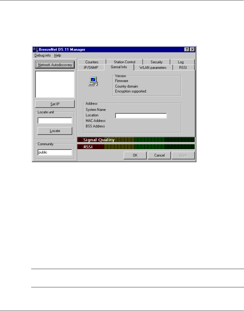
3.1.4 General Info Tab
The General Info tab displays general information regarding the unit's firmware and
hardware versions, and general unit address information.
Figure 3-5. General Info Tab
•1 Firmware - The current firmware version.
•2 Hardware - The current hardware version.
•3 System Name - The name of the selected unit.
•4 Location - Location of the selected unit.
•5 MAC Address - MAC address of the selected unit.
•6 BSS Address - In the RB-DS.11, this defines the BSS address (the BU-DS.11 that
the unit is associated with). In the BU-DS.11, it defines the MAC address of the
unit.
Note: You can select a unit's address either by selecting the address from the list, or
typing it directly.
The DS.11 Management Utility
User's Guide 3-8 BreezeNET BU-DS.11/RB-DS.11
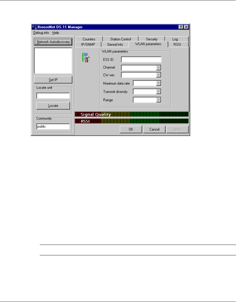
3.1.5 WLAN Parameters Tab
Figure 3-6. WLAN Parameters Tab
•1 ESSID - An ASCII string of up to 32 characters used to identify a WLAN that
prevents the unintentional merging of two co-located WLANs. It is essential that
the ESSID is set to the same value in all stations and Wireless Base Stations in
the extended WLAN. The ESSID field is case-sensitive.
•2 Channel - Select that the unit will use by selecting a value (range: 1-14) from the
pulldown menu. Refer to Table 3-1 for the list of corresponding frequencies.
When the RB-DS.11 unit will power up, it will automatically change channels,
search for the BU-DS.11 unit and synchronize with it; there is therefore no need
for channel assignment. Once the channel on the RB-DS.11 is assigned, it will no
longer change channels automatically.
Note: The channel selection must match the selection at the other side of the link.

The DS.11 Management Utility
BreezeNET BU-DS.11/RB-DS.11 3-9 User’s Guide
Table 3-1. Frequency Selection List
Channel
Selection Frequency
1 2412 MHz
2 2417 MHz
3 2422 MHz
4 2427 MHz
5 2432 MHz
6 2437 MHz
7 2442 MHz
8 2447 MHz
9 2452 MHz
10 2457 MHz
11 2462 MHz
•1 CW Win - select the contention window size to 15 or 31. The contention window
backoff algorithm is a well know method used to resolve contention between
different stations wanting to access the medium. More information on the
considerations for setting this parameter can be found in the DS.11 FAQ in
Appendix B.
•2 Maximum data rate - By default, the unit adaptively selects the highest possible
rate for transmission. Under certain conditions (for range/speed trade-off) you
may decide not to use the higher rates. Possible values are 2, or 5.5 or 11 Mbps.
The default value is 11 Mbps.
•3 Transmit diversity - Set the antenna diversity option, which can be Antenna No. 1,
No. 2, or both (default: both antennas).
Note: In the present product release, antenna diversity is not supported; therefore,
always select Antenna No. 1.
•4 Range - Select the operative range of your WLAN in the drop down list.
The DS.11 Management Utility
User's Guide 3-10 BreezeNET BU-DS.11/RB-DS.11
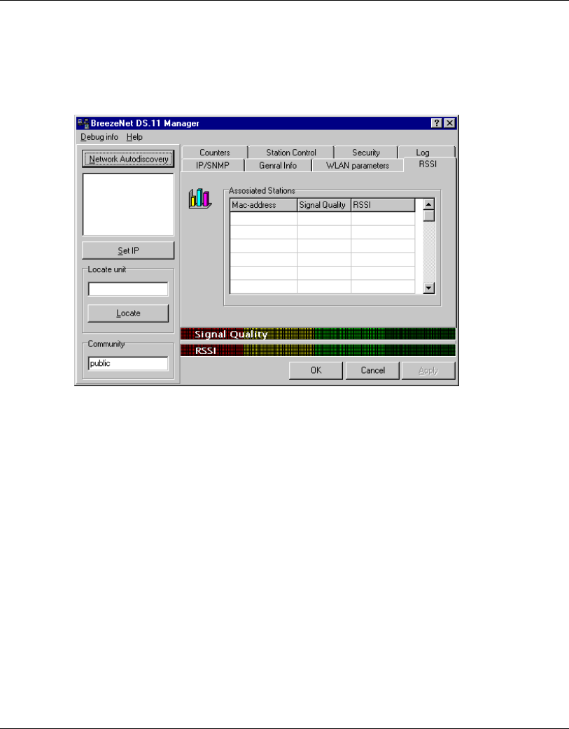
3.1.6 RSSI Tab
This tab only appears for BU-DS.11 units and allows you to view signal quality of all
the associated clients (RB-DS.11).
Figure 3-7. RSSI Tab
Select an IP address as explained previously in Section 0.
In the Associated Stations table, you can see all the stations associated with the
selected unit and their signal quality.
The DS.11 Management Utility
BreezeNET BU-DS.11/RB-DS.11 3-11 User’s Guide
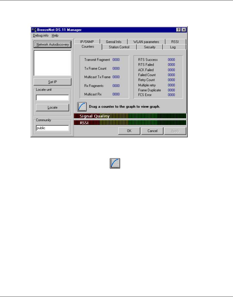
3.1.7 Counters Tab
Figure 3-8. Counters Tab
Select a counter and drag it to the icon to view the graph.
•1 Transmit Fragment - The number of transmitted frames. The count includes data,
control, management frames and the number of retransmissions of data frames
(for example, if the same data frame is retransmitted ten times then the count will
increase ten times).
•2 Tx Frame Count - The number of frames transmitted to the wireless media. The
count includes the first transmission of data frames (without retransmissions),
and the number of control and management frames.
•3 Multicast Tx Frames- The number of transmitted multicast frames.
•4 Rx Fragments - The number of frames received, including data, control, and
duplicate data frames.
•5 Multicast Rx - The number of received multicast frames.
•6 RTS Success - The number of successful Request To Send frames sent.
•7 RTS Failed - The number of failed Request To Send frames sent by the station.
The DS.11 Management Utility
User's Guide 3-12 BreezeNET BU-DS.11/RB-DS.11
•8 ACK Failed - The number of times the station stopped transmitting a frame after
failing to receive an acknowledgment packet.
•9 Failed Count - This counter is incremented when a packet is not transmitted
successfully due to the number of transmit attempts exceeding either the Short
Retry Limit or Long Retry Limit. These thresholds can be set by users that are in
the Technician login mode.
•10 Retry Count - The number of retransmissions.
•11 Multiple Retry - This counter is incremented when an packet is successfully
transmitted after more than one retransmission.
•12 Frame Duplicate - The number of duplicate frames that were sent or received.
•13 FCS Error - The number of CRC errors.
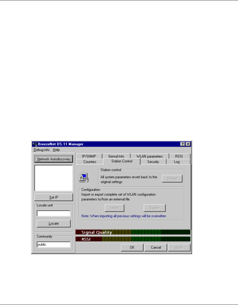
3.1.8 Station Control Tab
Figure 3-9. The Station Control Tab
Station Control - Click the Reset button to revert to the factory default settings.
The DS.11 Management Utility
BreezeNET BU-DS.11/RB-DS.11 3-13 User’s Guide
WARNING! This will erase all settings.
Configuration - Click Import/Export to import or export a complete set of
configuration parameters to an external file.
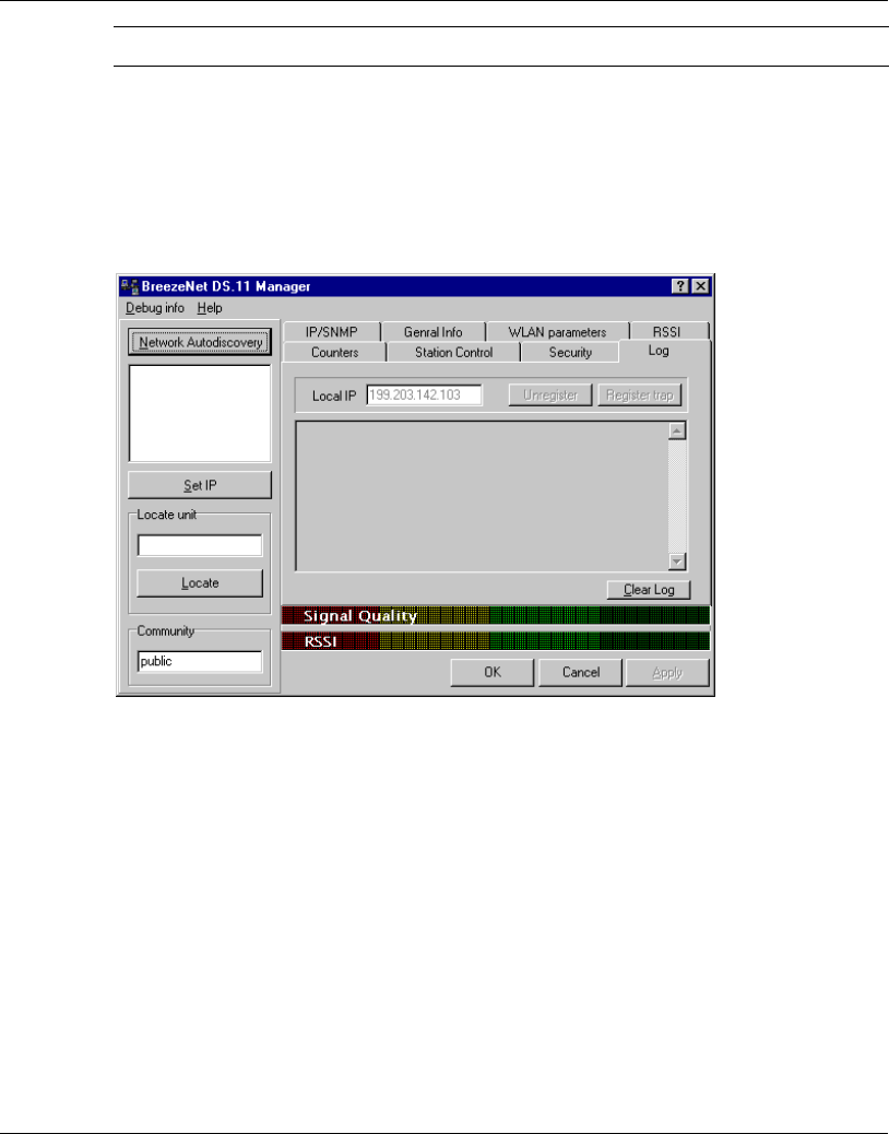
3.1.9 Log Tab
Figure 3-10. Log Tab
When an event occurs, a trap is sent to the defined host address. The Log tab allows
you to configure the host address to which the traps are sent.
A list of the last traps is displayed in the event log area, below the Local IP field.
The DS.11 Management Utility
User's Guide 3-14 BreezeNET BU-DS.11/RB-DS.11
The default host address is the IP address of the PC running the DS.11 Management
utility.
1. Select the IP address as explained in Section 0. The selected address appears in
the Local IP field.
2. Click the button to register this address as the host address.
3. Repeat Step 2 for all the IP addresses you wish to send traps to.
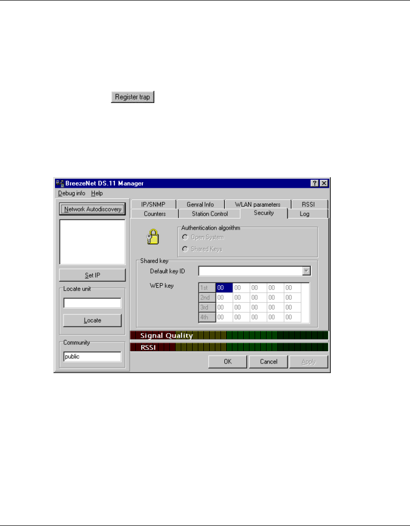
3.1.10 Security Tab
Figure 3-11. Security Tab
The BU-DS.11 can use one of the following authentication algorithms (as defined in
the 802.11 standard).
•1 Open System – any station in the WLAN can associate with a BU-DS.11 and
receive and transmit data (null authentication).
•2 Shared Key – only stations using a shared key encryption identified by the BU-
DS.11 are allowed to associate with it. You can only select this option if the card
was ordered with the Privacy option. When the option is ordered, the words

The DS.11 Management Utility
BreezeNET BU-DS.11/RB-DS.11 3-15 User’s Guide
Encryption Supported are displayed in the Version box in the General Info tab
shown in Figure 3-5 on page 3-7.
Values: Unknown Card is not inserted.
Implemented Shared Key authentication is enabled.
Not Implemented Shared Key authentication is disabled. Only
open system authentication is available in
this mode.
If you selected the Shared Key algorithm, proceed to set the following parameters:
•1 Default Key ID – Sets the default key for encryption in the Authentication
process. This is the encryption key that will be used for transmissions between
the station and the BU-DS.11.
•2 WEP Key – Define the encryption keys used for transmissions between the
station and the BU-DS.11. Specify each key by clicking the appropriate WEP Key
row (First, Second, Third or Fourth) and entering 10 Hex digits (5 pairs of
characters) for each of the 4 keys.
3.1.11 Debug Info(rmation)
This option allows you to create a log file named BreezeLog.log. You can send this log
file to BreezeCOM technical support and receive help based on the information
recorded in this file.
To start recording, open the Debug Info option and select Start Log.
When you finish recording (usually after 24 hours) select Stop Log and send the file
to BreezeCOM technical support representatives.

System Troubleshooting
BreezeNET BU-DS.11/RB-DS.11 4-1 User’s Guide
4. SYSTEM TROUBLESHOOTING
The following troubleshooting guide provides answers to some of the more common
problems which may occur when installing and using the BreezeNET DS.11. If
problems not mentioned in this guide should arise, checking the Ethernet and WLAN
counters may help (see Section 3.1.7). If the problem persists, please feel free to
contact your local distributor or the BreezeCOM Technical Support Department.
4.1 Troubleshooting Guide
Table 4-1. Troubleshooting
Problem and
Indication Possible Cause Corrective Action
No Power to Unit.
Power LED is off.
1. Power cord is not
properly connected.
2. Power supply is
defective.
1. Verify power cord is properly connected
to the BreezeNET unit and to the power
outlet.
2. If this is not the cause, replace the power
supply.

System Troubleshooting
User's Guide 4-2 BreezeNET BU-DS.11/RB-DS.11
Problem and
Indication Possible Cause Corrective Action
Failure to establish
wireless link. LINK
LED is off and unit
resets every few
minutes.
1. Power supply to
units may be faulty
2. The RB-DS.11 units
may not have the same
ESSID as the BU-
DS.11.
1. Verify power to units.
2. Verify that all units in the network have
the same ESSID as the BU-DS.11 (ESSID
must be identical in all units in the WLAN;
the ESSID is case sensitive). Check that the
units are on the same channel.
•1 Verify wireless link:
•2 Set BU-DS.11 and Bridge unit side by
side.
•3 Power on each unit and see if a
wireless link is established (even “D”
models without their external antennas
should establish a link if placed side by
side with the BU-DS.11).
•4 If the units fail to associate, reset units
to factory default values reset unit (see
Section 2.3). The units should now
establish a wireless link.
Failure to establish
wireless link (“D”
models/external
antennas)
1. Power supply to
units may be faulty.
2. Cables may be
improperly connected
3. There may be some
problem with antenna
installation.
1. Verify power to units.
2. Verify that all cables are connected
securely.
3. Refer to previous Section and verify
wireless link between the units.
4. Verify that the antenna(s) are properly
installed (see relevant section in this
manual):
•5 Check antenna alignment.
•6 Verify that antenna polarization is the
same at both ends.
•7 Verify that the range matches
specifications.
•8 Verify line-of-sight/antenna
alignment/antenna height.

System Troubleshooting
BreezeNET BU-DS.11/RB-DS.11 4-3 User’s Guide
Problem and
Indication Possible Cause Corrective Action
Wireless link
established, but there
is no Ethernet
activity (BU-DS.11
and RB-DS.11 units).
1. Ethernet hub port or
UTP cable is faulty.
Ethernet port in unit is
faulty. The station is
associated to a BU-
DS.11 unit that is not
connected correctly to
the LAN
1. Check that the LINK LED is lighted
Green. If this is not the case, the port is
inactive. Try another port on the hub or
another UTP cable.
2. Verify that Ethernet port in unit is
working. Ping unit to verify Ethernet
connection.
3. Verify that you are using a cross-over
UTP cable (pins 1 & 3, 2 & 6) if connected
directly to workstation, or a straight-
through cable if connected to a hub.
4. Check the unit’s LINK LED indicator
and check the Ethernet counters in the
monitor to verify Ethernet activity
(see Section 3.1.6). Check that there is no
other BU-DS.11 that has the same channel
and ESSID, but is not connected to the
LAN.

Software DownLoad Procedure
BreezeNET BU-DS.11/RB-DS.11 5-1 User’s Guide
5. SOFTWARE DOWNLOAD PROCEDURE
1. Set the unit's IP address, using the DS.11 Management utility, and verify that the
PC's IP address belongs to the same Subnet Mask as the unit.
2. Ping the unit's IP address. Make sure that the Ping replies are being received.
3. Use the TFTP utility on the PC:
) Syntax: TFTP [-i] destination host [PUT] source file [password]
) Example: TFTP -i 199.203.141.30 put ap1100.arm private
Download will be completed within two minutes, and a message of successful file
transfer will be shown on the screen.
4. The unit resets itself automatically.
5. Check the diagnostics LEDs to verify that there is not hardware failure, and use
the DS.11 Management utility to make sure that the version number is correct.
Note: Do not disconnect any cables or try to stop the process before downloading is
completed.
All configured parameters are kept during the upgrade/download procedure.

Installing Accessories
BreezeNET BU-DS.11/RB-DS.11 6-1 User’s Guide
6. INSTALLING ACCESSORIES
This chapter introduces some of the accessories available for specific installations,
and describes how to install them.
6.1 RFS 122 Radio Frequency Splitter
The RFS 122 Radio Frequency Splitter is used to split the RF signal generated by a
transmitter into two signals. These signals are then sent to two different and
independent antennas. The RFS 122 enables radio transmission using two directional
antennas connected to the same port of the BreezeNET DS.11 unit. Similarly, the
splitter is used to combine two receiving antennas to one antenna connector.
Before installing the RFS 122, configure the BreezeNET DS.11 unit using the DS.11
Management utility to transmit through Antenna 2 only (see Section 3.1.5), and
connect the RFS 122 to antenna connector 2.
Technical Specifications
BreezeNET BU-DS.11/RB-DS.11 7-1 User’s Guide
7. TECHNICAL SPECIFICATIONS
7.1 Supported Standards
• Compliant with ETS 300 328 and ETS 300 826 (CE marked)
• IEEE 802.11 TGb standard for Wireless LAN at 11 and 5.5 Mbps
• IEEE 802.11 standard for 1 and 2 Mbps
• Most of the major networking protocols (including IP, IPX)
7.2 Power Specifications
Power Supply Input (via
Indoor unit) 207VAC - 253VAC 250mA
OR
100VAC - 120VAC 500mA
AC Mains option is factory wired.
Power Supply Output (from
Indoor unit to Outdoor unit) 48VDC
7.3 Wired LAN Interface
Compliant with Ethernet/IEEE 802.3 CSMA/CD
Physical interface 10Base-T
Connector type RJ-45
Network operating systems All
Wireless LAN interface Compliant with IEEE 802.11
Technical Specifications
User's Guide 7-2 BreezeNET BU-DS.11/RB-DS.11
7.4 Radio Specifications
Type Direct sequence spread spectrum
Range Europe/ETSI: 15Km
USA/FCC: 24Km (15 miles)
Transmit power Range: 24dBm (max) to -4dBm (min)
Dependable upon Antenna type , system app. & country
regulation.
Frequency range 2.4-2.4835 Ghz
Number of channels Europe: 13 (3 non-overlapping)
US: 11 (3 non-overlapping)
France: 4 (1 non-overlapping)
7.5 Sensitivity
@ 1Mbps -92dBM, IE-5 BER
@ 2Mbps -88dBM, IE-5 BER
@ 5.5Mbps -87dBM, IE-5 BER
@ 11Mbps -85dBM, IE-5 BER
7.6 Configuration and Management
Configuration and setup SNMP and Windows-based Manager utility
Site survey Yes
LED indicators Yes
SNMP management Yes

Technical Specifications
BreezeNET BU-DS.11/RB-DS.11 7-3 User’s Guide
7.7 Specific Features
Data rate • 11 Mbps
• 5.5 Mbps
• 2 Mbps
• 1Mbps
Utility Software BreezeNET Management utility, runs on Windows 95
and Windows NT
7.8 Size
Dimensions (without
antennas) TBD
7.9 Environmental
Indoor Unit Outdoor Unit
Operating
temperature (ambient) 0°C to 40°C
(32°F to 104°F) -40°C to 50°C
(-40°F to 122°F)
Storage temperature -5°C to 70°C
(23°F to 158°F) -5°C to 70°C
(23°F to 158°F)
Operating humidity 10% to 90%
(non-condensing) 10% to 90%
(non-condensing)
Storage humidity 10% to 90%
(non-condensing) 10% to 90%
(non-condensing)
Appendix A. Radio Signal Propagation
BreezeNET BU-DS.11/RB-DS.11 A-1 User’s Guide
APPENDIX A. RADIO SIGNAL PROPAGATION
A.1 Radio Signal Propagation
A.1.1 Introduction
This section explains and simplifies many of the terms relating to antennas and RF
(Radio Frequency) used when dealing with an RF installation system.
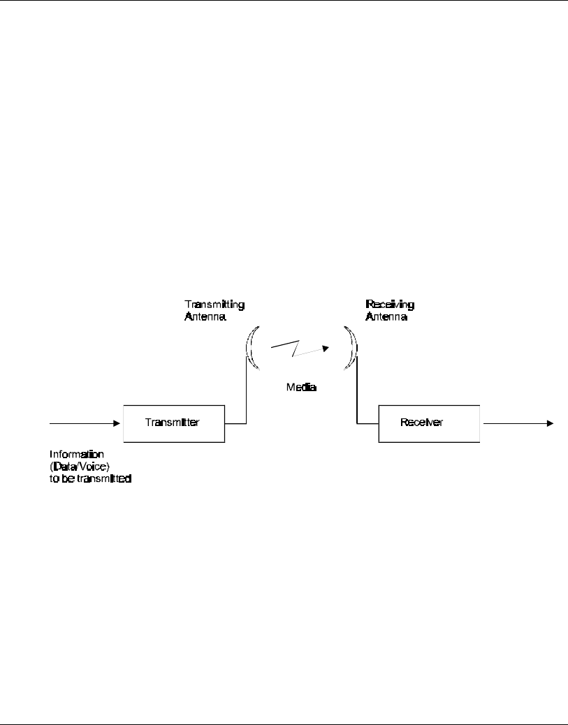
The following diagram depicts a typical radio system:
Figure A-1. A Typical Radio System
A radio system transmits information to the transmitter. The information is
transmitted through an antenna which converts the RF signal into an electromagnetic
wave. The transmission medium for electromagnetic wave propagation is free space.
The electromagnetic wave is intercepted by the receiving antenna which converts it
back to an RF signal. Ideally, this RF signal is the same as that originally generated by
the transmitter. The original information is then demodulated back to its original form.
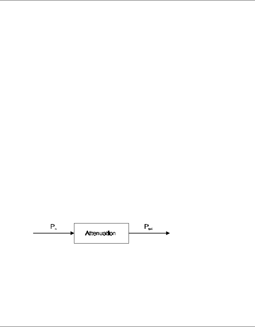
Appendix A. Radio Signal Propagation
User's Guide A-2 BreezeNET BU-DS.11/RB-DS.11
A.1.2 RF Terms and Definitions
dB
The dB convention is an abbreviation for decibels. It shows the relationship between
two values.
RF Power Level
RF power level at either the transmitter output or the receiver input is expressed in
Watts. It can also be expressed in dBm. The relation between dBm and Watts can be
expressed as follows:
PdBm = 10 x Log Pmw
For example: 1 Watt = 1000 mW; PdBm = 10 x Log 1000 = 30 dBm
100 mW; PdBm = 10 x Log 100 = 20 dBm
For link budget calculations, the dBm convention is more convenient than the Watts
convention.
Attenuation
Attenuation (fading) of an RF signal is defined as follows:
Figure A-2. Attenuation of an RF signal
Pin is the incident power level at the attenuated input
Pout is the output power level at the attenuated output
Attenuation is expressed in dB as follows: PdB = -10 x Log (Pout/Pin)

Appendix A. Radio Signal Propagation
BreezeNET BU-DS.11/RB-DS.11 A-3 User’s Guide
For example: If, due to attenuation, half the power is lost (Pout/Pin = 1/2),
attenuation in dB is -10 x Log (1/2) = 3dB
Path Loss
Loss of power of an RF signal traveling (propagating) through space. It is expressed in
dB. Path loss depends on:
• The distance between transmitting and receiving antennas
• Line of sight clearance between the receiving and transmitting antennas
• Antenna height
Free Space Loss
Attenuation of the electromagnetic wave while propagating through space. This
attenuation is calculated using the following formula:
Free space loss = 32.4 + 20xLog(FMhz) + 20xLog(RKm)
F is the RF frequency expressed in Mhz.
R is the distance between the transmitting and receiving antennas.
At 2.4 Ghz, this formula is: 100+20xLog(RKm)
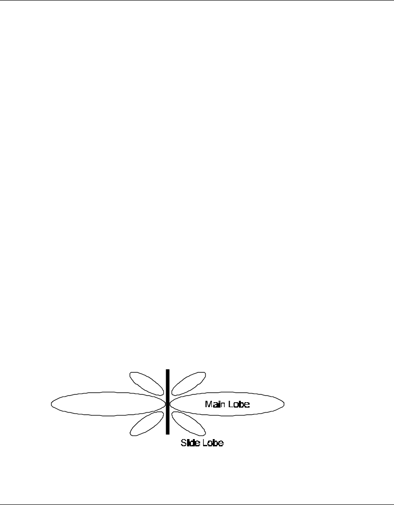
Appendix A. Radio Signal Propagation
User's Guide A-4 BreezeNET BU-DS.11/RB-DS.11
Antenna Characteristics
Isotropic Antenna
A hypothetical antenna having equal radiation intensity in all directions. Used as a zero
dB gain reference in directivity calculation (gain).
Antenna Gain
A measure of directivity. It is defined as the ratio of the radiation intensity in a given
direction to the radiation intensity that would be obtained if the power accepted by the
antenna was radiated equally in all directions (isotropically). Antenna gain is expressed
in dBi.
Radiation Pattern
A graphical representation in either polar or rectangular coordinates of the spatial
energy distribution of an antenna.
Side Lobes
The radiation lobes in any direction other than that of the main lobe.
Omni-directional Antenna
Radiates and receives equally in all directions in azimuth. The following diagram
shows the radiation pattern of an omni-directional antenna with its side lobes in polar
form.
Figure A-3. Side View
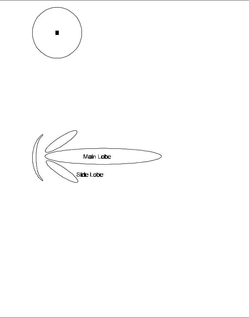
Appendix A. Radio Signal Propagation
BreezeNET BU-DS.11/RB-DS.11 A-5 User’s Guide
Figure A-4. Top View
Directional Antenna
Radiates and receives most of the signal power in one direction. The following
diagram shows the radiation pattern of a directional antenna with its side lobes in polar
form:
Figure A-5. Radiation Pattern of Directional Antenna
Antenna Beamwidth
The directiveness of a directional antenna. Defined as the angle between two half-
power (-3 dB) points on either side of the main lobe of radiation.

Appendix A. Radio Signal Propagation
User's Guide A-6 BreezeNET BU-DS.11/RB-DS.11
System Characteristics
Receiver Sensitivity
The minimum RF signal power level required at the input of a receiver for certain
performance (e.g. BER).
EIRP (Effective Isotropic Radiated Power)
The antenna transmitted power. Equal to the transmitted output power minus cable loss
plus the transmitting antenna gain.
Pout Output power of transmitted in dBm
CtTransmitter cable attenuation in dB
GtTransmitting antenna gain in dBi
GrReceiving antenna gain in dBi
PlPath loss in dB
CrReceiver cable attenuation is dB
SiReceived power level at receiver input in dBm
PsReceiver sensitivity is dBm
Si = Pout - Ct + Gt - Pl + Gr - Cr
EIRP = Pout - Ct + Gt

Appendix A. Radio Signal Propagation
BreezeNET BU-DS.11/RB-DS.11 A-7 User’s Guide
Example:
Link Parameters:
Frequency: 2.4 Ghz
Pout = 4 dBm (2.5 mW)
Tx and Rx cable length (Ct and Cr) = 10 m. cable type RG214 (0.6 dB/meter)
Tx and Rx antenna gain (Gt and Gr) = 18 dBi
Distance between sites = 3 Km
Receiver sensitivity (Ps) = -84 dBm
Link Budget Calculation
EIRP = Pout - Ct + Gt = 16 dBm
Pl = 32.4 + 20xLog(FMhz) + 20xLog(RKm) ≅ 110 dB
Si = EIRP - Pl + Gr - Cr = -82 dBm
In conclusion, the received signal power is above the sensitivity threshold, so the link
should work. The problem is that there is only a 2 dB difference between received
signal power and sensitivity. Normally, a higher margin is desirable due to fluctuation
in received power as a result of signal fading.
Signal Fading
Fading of the RF signal is caused by several factors:
• Multipath
The transmitted signal arrives at the receiver from different directions, with different
path lengths, attenuation and delays. The summed signal at the receiver may result in an
attenuated signal.
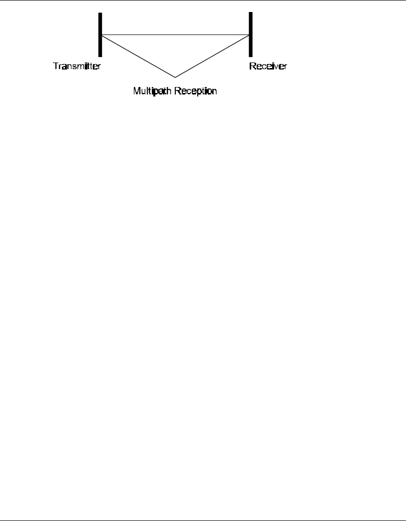
Appendix A. Radio Signal Propagation
User's Guide A-8 BreezeNET BU-DS.11/RB-DS.11
Figure A-6. Multipath Reception
Bad Line of Sight
An optical line of sight exists if an imaginary straight line can connect the antennas on
either side of the link.
Radio wave clear line of sight exists if a certain area around the optical line of sight
(Fresnel zone) is clear of obstacles. A bad line of sight exists if the first Fresnel zone
is obscured.
• Link Budget Calculations
• Weather conditions (rain, wind, etc.)
At high rain intensity (150 mm/hr), the fading of an RF signal at 2.4 GHz may reach a
maximum of 0.02 dB/Km. Wind may cause fading due to antenna motion.
• Interference
Interference may be caused by another system on the same frequency range, external
noise, or some other co-located system.
The Line of Sight Concept
An optical line of sight exists if an imaginary straight line can be drawn connecting the
antennas on either side of the link.
Clear Line of Sight
A clear line of sight exists when no physical objects obstruct viewing one antenna
from the location of the other antenna.
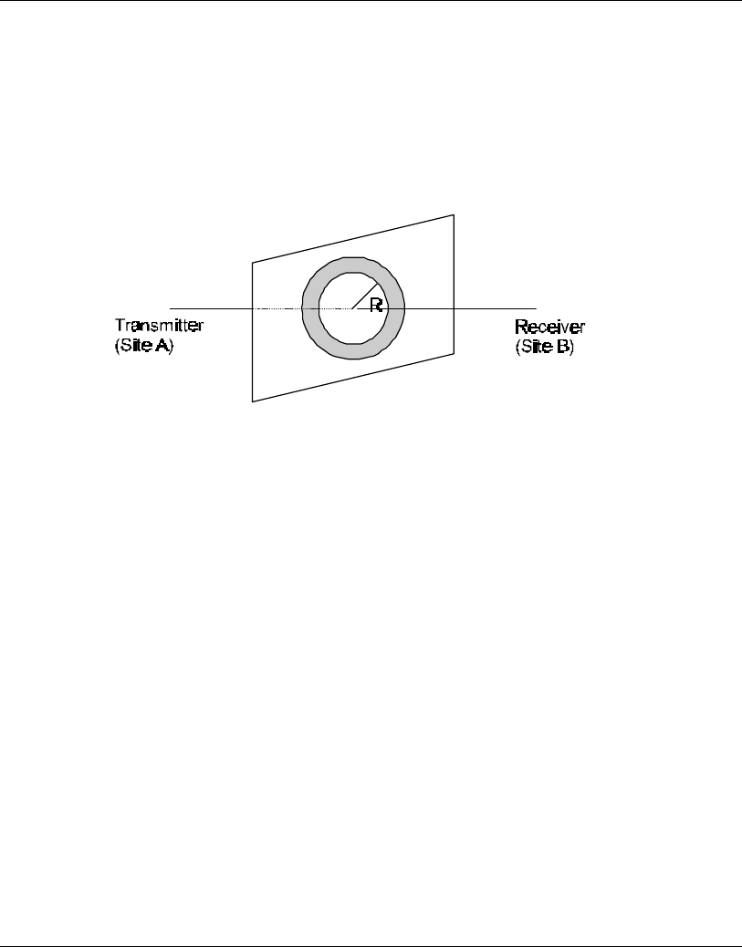
Appendix A. Radio Signal Propagation
BreezeNET BU-DS.11/RB-DS.11 A-9 User’s Guide
A radio wave clear line of sight exists if a defined area around the optical line of sight
(Fresnel Zone) is clear of obstacles.
Fresnel Zone
The Fresnel zone is the area of a circle around the line of sight.
The Fresnel Zone is defined as follows:
Figure A-7. Fresnel Zone
R = ½ √ (λxD)
R: radius of the first Fresnel zone
λ: wavelength
D: distance between sites
Appendix A. Radio Signal Propagation
User's Guide A-10 BreezeNET BU-DS.11/RB-DS.11
Figure A-8. Fresnel Zone Clear of Obstacles
When at least 80% of the first Fresnel Zone is clear of obstacles, propagation loss is
equivalent to that of free space.
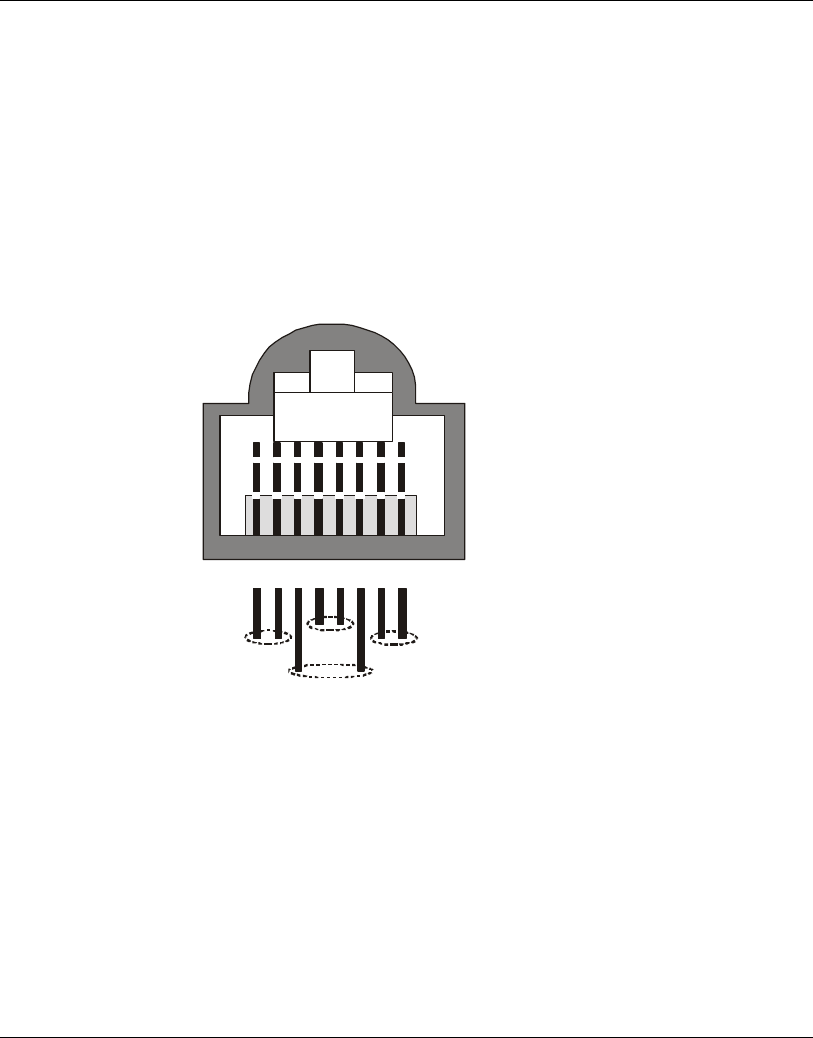
Appendix B. Preparing the Indoor-to-Outdoor Cable
BreezeNET BU-DS.11/RB-DS.11 B-1 User’s Guide
APPENDIX B. PREPARING THE INDOOR TO
OUTDOOR CABLE
The Indoor-to-Outdoor cable provides pin-to-pin connection on both sides. It is
supplied open-ended at the one side, to allow the installer to conveniently route the
cable into the waterproof seal off the Outdoor unit.
Figure 7-1 shows the wire pair connections required for the Indoor-to-Outdoor cable.
12345678
1 + 2 4 + 5 7 + 8
3 + 6
Figure 7-1. Ethernet Connector Pin Assignments
The pins are supplied crimped, with an additional set of spare uncrimped pins. Use the
contact insertion and removal tool supplied with the unit (Amphenol P/N 17 D 438
SP) to insert the crimped pins into the RJ45 connector.

Appendix C. DS.11 FAQ
BreezeNET BU-DS.11/RB-DS.11 C-1 User’s Guide
APPENDIX C. DS.11 FAQ
How many BU-DS.11 or RB-DS.11 units can be co-located on the same building top or tower?
You can co-locate up to 3 BU-DS.11 or RB-DS.11 units on the same structure. Each
unit is assigned to one of the non-overlapping channels, 1, 6, or 11.
What is the antenna separation requirement for co-locating BU-DS.11 or RB-DS.11 units on
the same building top or tower?
The antennas should be mounted at least 2 feet apart when using UNI-16’s, 15 feet
when using UNI-24’s, and 75 feet when using OMNI-8’s. For omni antennas, the
maximum link distance is reduced by up to 50%. Greater separation will improve the
link distance.
Can my FH network operate in the same area as the DS?
Yes, in a co-located network, both products will suffer some loss in performance. This
depends on network utilization. For example, the higher the utilization of the FH
network, the higher the level of impact on the DS network, and visa versa. Typically, in
light to moderate utilized networks, the performance loss is not perceivable.
Can I use DS.11 Bridges to feed a FH distribution point?
Yes, bandwidth sharing between the DS and FH products can be minimized if the
network is designed using cross polarized directional antennas, and as much spatial
separation as possible. Contact technical support for assistance with this.
What is the throughput of the DS.11?
The BU-DS.11/RB-DS.11 bridge link typical performance is 4.2Mbps using TCP and
6.2Mbps using UDP. For long range links, the performance will drop about 5%.

Appendix C. DS.11 FAQ
User's Guide C-2 BreezeNET BU-DS.11/RB-DS.11
Why are there 11 channels and only 3 usable?
The IEEE802.11 specification calls out 11 selectable channels (USA) between
2414MHz and 2462MHz. Because of the transmission bandwidth of the DS
modulation, only 3 channels are non-overlapping. Those are channels 1, 6, and 11,
therefore, only 3 systems may be co-located. The other channels may be used,
however, if used with another DS system co-located on another nearby channel, the
overlap will cause them to share the bandwidth yielding no increase in aggregate data
bandwidth. When operating in a single channel network, the other channels may be
used to move away from any in band interference that may exist.
What if the DS.11 link experiences interference?
If interference is affecting the DS.11 link, one of the other channels may be selected
to operate away from the frequency of the interference. Also, physically re-locating
the antennas may help.
What is the typical latency of a BU-DS.11/RB-DS.11?
A point to point link would realize about 3mS latency.
Can the BU-DS.11/RB-DS.11 firmware be upgraded?
Yes, the firmware in the BU-DS.11/RB-DS.11 is stored in flash and is upgraded using
the built in TFTP server.
Can just anyone erase my BU-DS.11/RB-DS.11 flash or change the firmware?
No, the TFTP server in the BU-DS.11/RB-DS.11 requires the SNMP write community
name (password) to perform an upgrade.
Can I corrupt my firmware flash when upgrading to a new version?
If the TFTP file transfer is interrupted during a flash update it is possible to corrupt the
firmware. Fortunately, the DS.11 has a backup flash, which contains the previous
version for firmware. If the primary flash is corrupt, then the backup is automatically
used to return the unit to an operating state.
When does the back up flash image get upgraded?
After completing a firmware upgrade, the backup flash containing the old firmware
version is overwritten with the new version on the new power on cycle.

Appendix C. DS.11 FAQ
BreezeNET BU-DS.11/RB-DS.11 C-3 User’s Guide
Can I downgrade my DS.11 firmware?
Yes, an earlier version of firmware can overwrite a newer version.
Can I keep the previous version of firmware? No and yes. The previous version of
firmware can not be kept on the DS.11 itself, but can be stored on your PC and loaded
if needed.
Does DS.11 support 802.1Q VLAN?
Yes, but the support is limited to transparent operation. Meaning, DS.11 does not take
any action on 802.1Q frames, but will transparently pass them within a VLAN network.
Can I change the regulatory domain (country) of my DS.11?
No. The regulatory domain is factory set.
How can I configure or manage my DS.11 if I forgot the SNMP Community name?
Press the reset button on the back panel with a paper clip. This will set the read and
write Community names to public and private, respectively.
How can I return the DS.11 unit to factory default settings?
There are two ways. One way is to use the Default button on the Station Control Tab in
the DS.11 Manager Utility. The other is to press and hold the reset button on the back
of the unit while powering on the unit. Remember that all settings including IP
addresses will be lost when setting defaults.
Can I use the BreezeNET PI-CAT5 product with my DS.11 unit?
No. The PI-CAT5 is specifically for the PRO.11 units only. The voltage is not the
same between the two devices.
Can I place the BU-DS.11/RB-DS.11 DS.11 unit outdoors?
No, not directly. The BU-DS.11/RB-DS.11 is specified to operate at 0°C to 40°C and
is not weather proof. It is best to mount the DS.11 indoors or in a protective cabinet.
Can I use the ODB-1 product with my DS.11 unit?
No. The ODB-1 is specifically for the PRO.11 units only.

Appendix C. DS.11 FAQ
User's Guide C-4 BreezeNET BU-DS.11/RB-DS.11
What is the maximum number of networked PC’s the BU-DS.11/RB-DS.11 can learn?
1024 network MAC addresses can be learned by the BU-DS.11/RB-DS.11.
Can the BU-DS.11/RB-DS.11 be used for multi-point as well as point to point links?
Yes. The BU-DS.11 can support multiple RB-DS.11 units creating a multi-point
network.
How many RB-DS.11 units can one BU-DS.11 support?
The maximum number of associations is 128.
What is the practical limit to the number of client bridges per BU-DS.11? And, what
performance can I expect for a multi-point link?
This really depends on average throughput expectations. All clients would have the
maximum throughput available for burst traffic, however the overall average would
depend on the utilization of the network. For example, in a heavily utilized network
needing about 350Kbps to 500kbps average net throughput per site, 9 to 12 RB-
DS.11’s would be the limit. For a moderately utilized network needing about 175Kbps
to 258Kbps average, 18 to 24 RB-DS.11’s should be used, and for a lightly used
network needing 32Kbps to 48Kbps average net throughput per site could use up to
128 RB-DS.11’s.
What is the range of the BU-DS.11/RB-DS.11 Bridges?
15 miles or 24Km can be achieved using the UNI-24 antenna kits for a point to point
link. Consult the antenna and accessory guide range tables for distances using other
antenna combinations.
What is the power supply ratings for the DS.11?
The DS.11 power supply is rated for 100 – 240VAC input (47-63Hz) and 9VDC at
1.67A output. Polarity doesn’t matter.
Can I use the same antenna systems and accessories on my DS.11 as on my PRO.11?
Yes. The RF connector on the DS.11 is the same unique SMA type as used on the
PRO.11, so all the same antennas and cables can be used.
What management options are available on DS.11?

Appendix C. DS.11 FAQ
BreezeNET BU-DS.11/RB-DS.11 C-5 User’s Guide
The BU-DS.11/RB-DS.11 DS.11 comes with a graphical management utility that
operates on any Windows based network ready PC. With this utility you can configure
and monitor every DS.11 on your network. You can also use the DS.11 SNMP MIB on
standard management platforms like SNMPc, and HP Openview.
Does the DS.11 offer out-of-band management?
No, the DS.11 does not offer out-of-band management, such as a serial port. The
DS.11 is managed in-band only via the DS.11 manager utility or SNMP.
Can I use the AMP250 or AMP500 on the DS.11?
No. The AMP250/500 products are not tested or certified for use with the DS.11
products.
What installation and site survey tools are available for BU-DS.11/RB-DS.11?
The DS.11 comes with a Windows based manager utility. With this utility you can
configure link parameters and monitor signal quality and RSSI (received signal
strength indication). Optimizing antenna alignment is done using the signal quality and
RSSI display. Any computer on the network can use this utility to manage the BU-
DS.11/RB-DS.11.
Is the DS.11 compatible with other DS equipment from other vendors?
Yes. However, for the outdoor bridges, interoperability can vary from vendor to
vendor, and in some cases it may not operate if the manufacturer’s implementation is
not pure 802.11. The BU-DS.11/RB-DS.11 can operate at 1 and 2Mbps with legacy
802.11 DS equipment, and at 5.5Mbps and 11Mbps with 802.11b High Rate DS
equipment.
Does the BU-DS.11/RB-DS.11 DS.11 support 802.1d spanning tree protocol?
No, the BU-DS.11/RB-DS.11 does not support spanning tree. This is because the BU-
DS.11 can also support roaming devices.
What is the normal PER (packet error rate) for the BU-DS.11/RB-DS.11?
The error rate will be about 4%-6% (transmitted fragments vs. retry count). This is
typical when operating in a non-interference environment at maximum range for bi-
directional traffic loads. If the traffic load is more uni-directional, then the PER will
be less.
What is the best value for the CW win parameter on the DS.11?

Appendix C. DS.11 FAQ
User's Guide C-6 BreezeNET BU-DS.11/RB-DS.11
Setting the CW win parameter to 31 for heavy bi-directional traffic loads will
minimize the PER. Setting the CW win to 15 will improve performance for more uni-
directional traffic loads. CW win 7 should only be used for short range point-to-point
links, and 63 should be used for large, long range multi-point links.