Alvarion Technologies IF-900 Broadband Wireless Access System User Manual BreezeACCESSS 900 System Manual
Alvarion Ltd. Broadband Wireless Access System BreezeACCESSS 900 System Manual
UserManual.wiki
>
Alvarion Technologies
>
IF 900 User Manual
User Manual
Navigation menu
Upload a User Manual
Namespaces
Wiki Guide
HTML
PDF
Info
Views
User Manual
Discussion / Help
Navigation
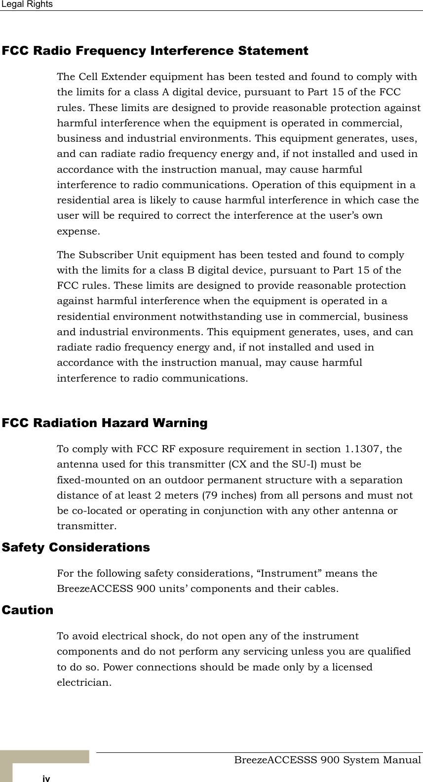
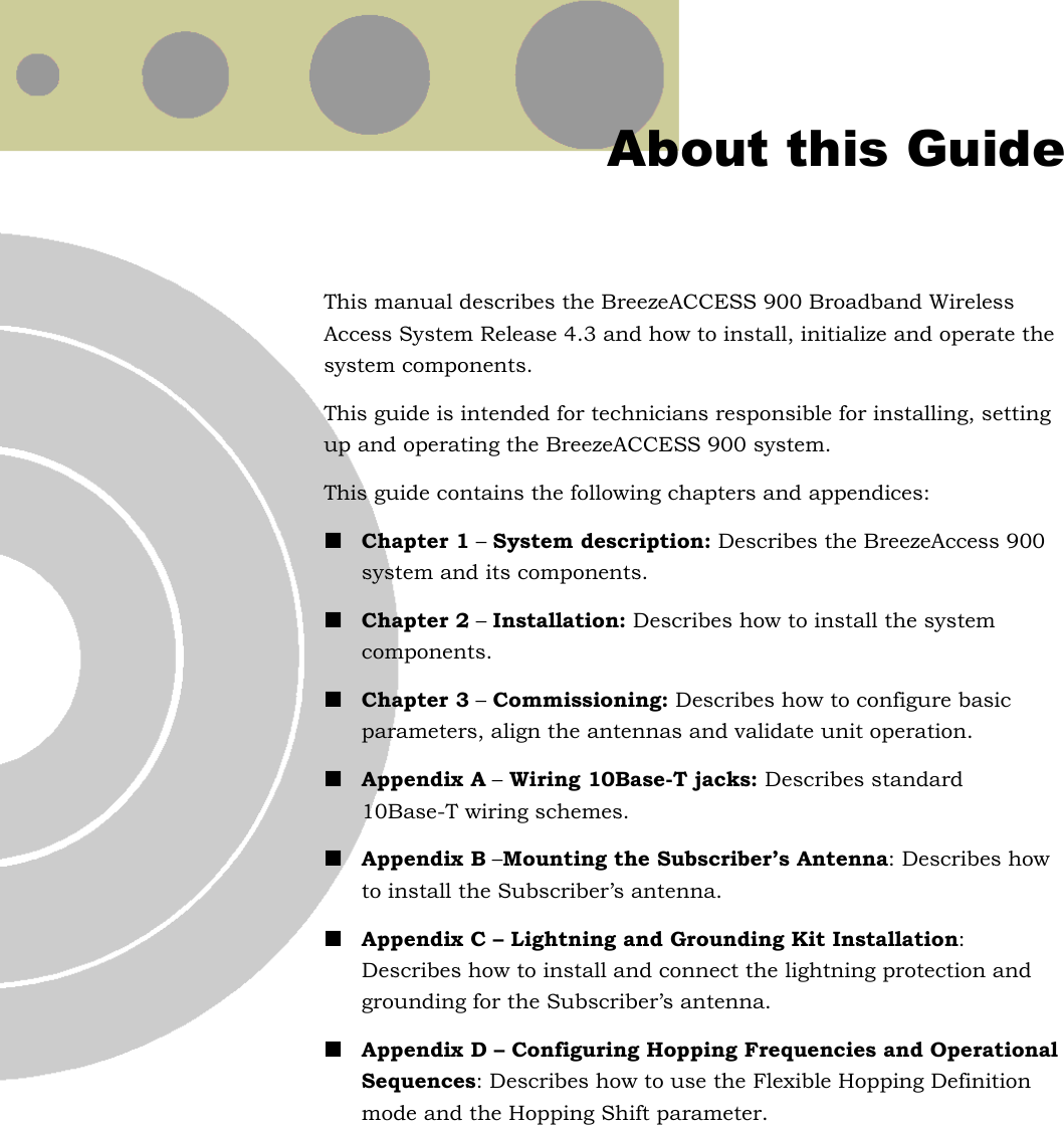
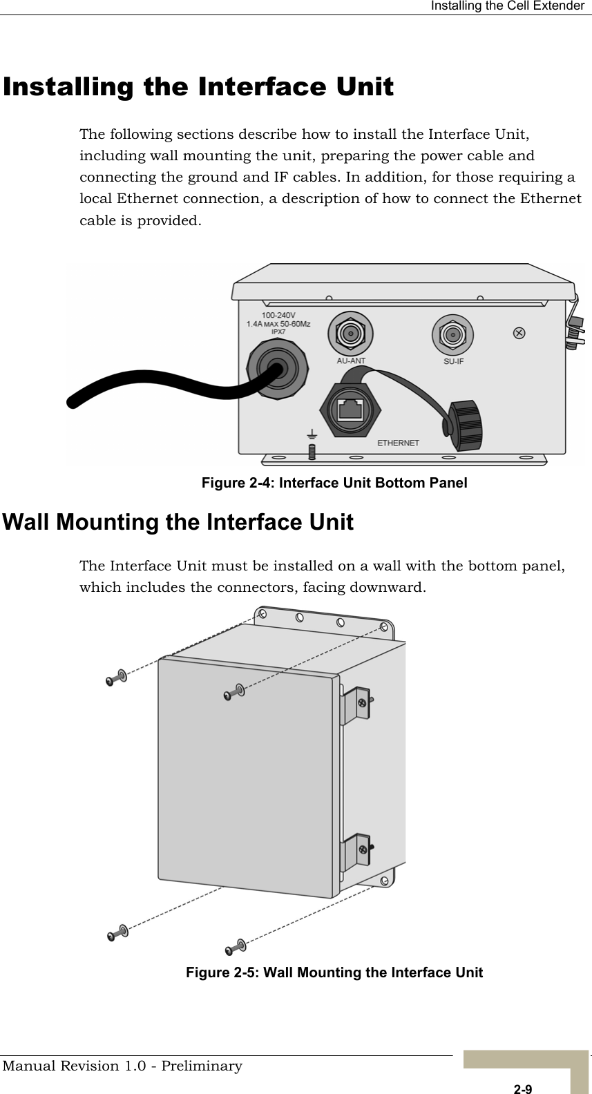

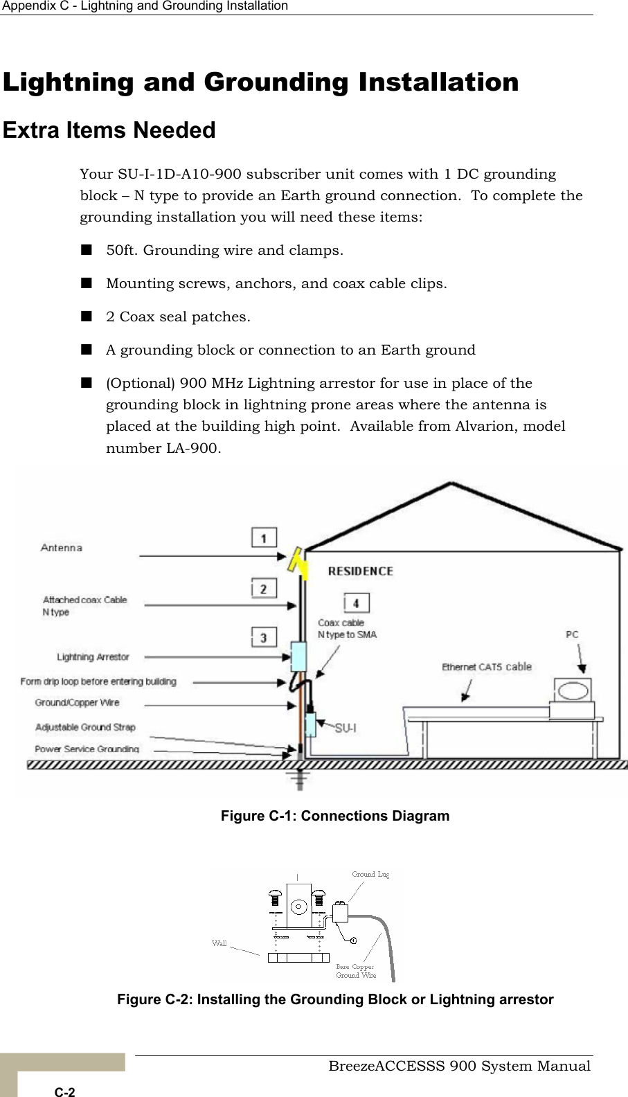
![Chapter 2 - Installation Installing the SU-I Subscriber Unit Installation Requirements This section describes all the supplies required to install the SU-I Subscriber Units and the items included in each installation package. Packing List for SU-I-1D-A10-900 Subscriber Unit The SU-I installation kit includes the following components: SU-I-1D Subscriber Unit with a wall mounting kit 5 VDC universal power adaptor Mounting bracket for wall or ceiling installation A torque key for the antenna connector Antenna cable kit (10ft and 20ft cables [LMR-240] and a DC grounding block) Antenna, including pole mounting hardware Additional Installation Requirements The following items are also required to install the Subscriber Unit: Grounding cables and other lightning protection materials according to specific installation requirements Straight Ethernet cable for connecting the Subscriber Unit to a PC For configuring basic parameters - A portable PC, with Ethernet NIC and Telnet software (or BreezeCONFIG ACCESS Configuration Utility) OR A portable PC with Terminal Emulation software and a Monitor cable Installation tools and materials, including appropriate means (e.g. a pole) for installing the antennas. A Wall/Roof Mounting Arm (P/N 872442 is available from Alvarion. BreezeACCESSS 900 System Manual 2-14](https://usermanual.wiki/Alvarion-Technologies/IF-900/User-Guide-341369-Page-48.png)


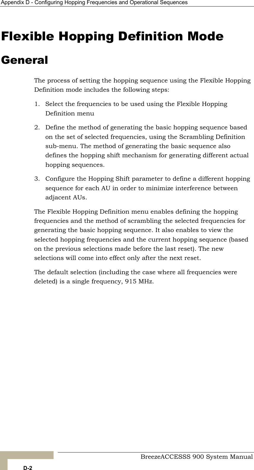
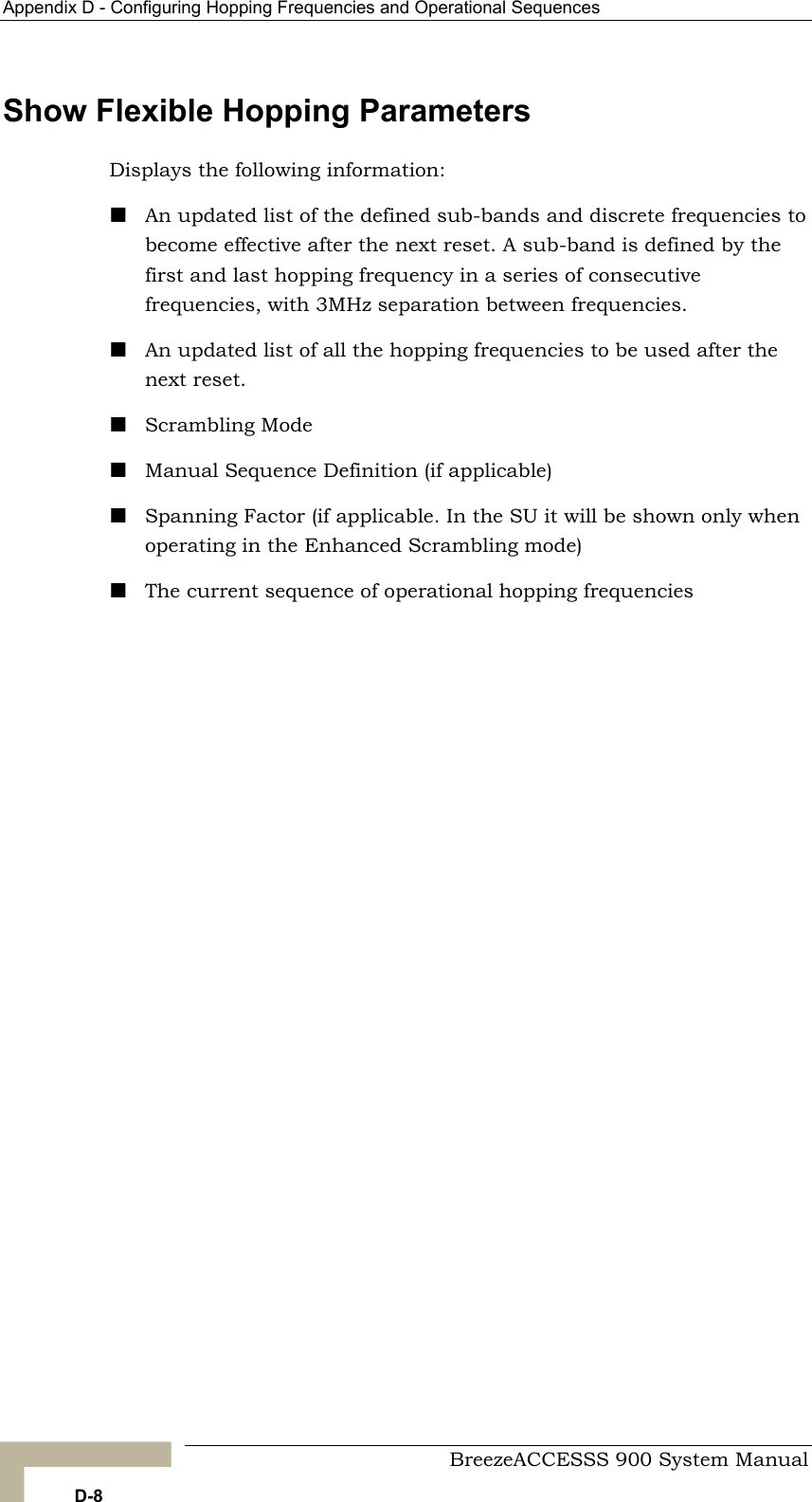
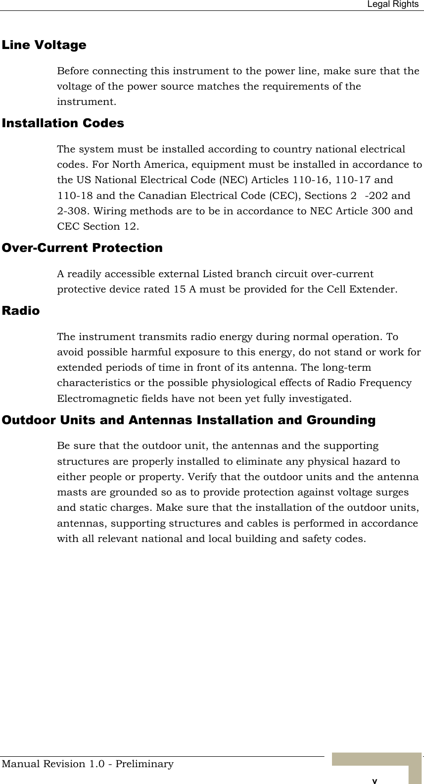
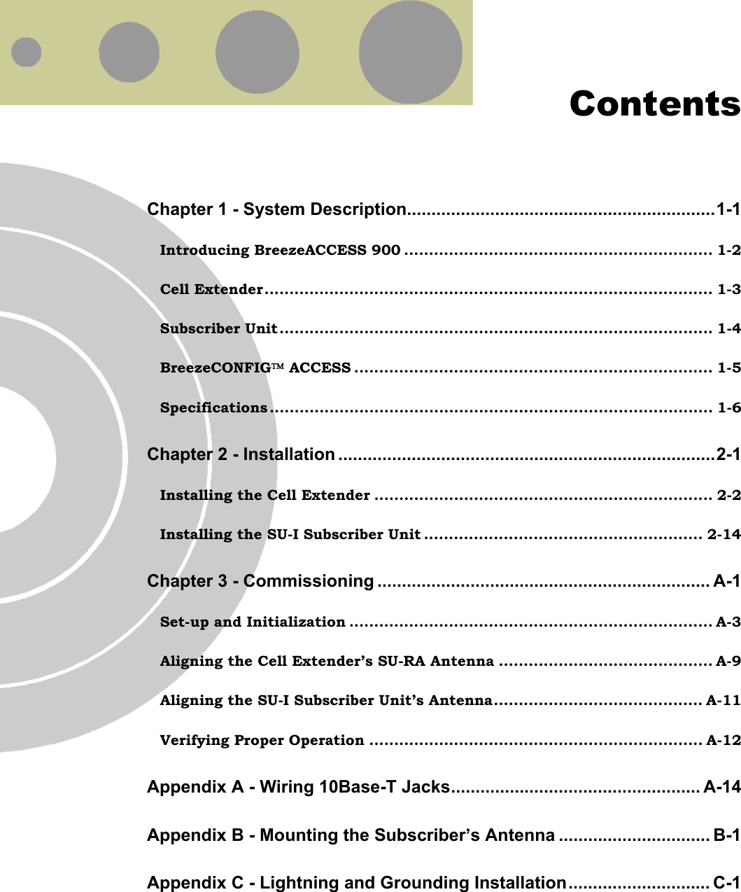
![Flexible Hopping Definition Mode The scrambled basic sequence can also be calculated using the formula: Px (j)= {[(j-1)*X]mod(N)}+1 Where: X is the Spanning Factor N is the number of channels in the sequence (modulus) J is the sequence index Example: N=8, X=3 P1(5)={[(1-1)*3}mod8}+1=1 P2(5)={[(2-1)*3}mod8}+1=6 od8}+1=5 od8}+1=2 P7(5)={[(7-1)*3}mod8}+1=7 P8(5)={[(8-1)*3}mod8}+1=4 And the basic scrambled sequence is: 1, 4, 7, 2, 5, 8, 3, 6. Manual Sequence Definition Manually defines the hopping sequence, using numbered channel indexes (from 1 to “Number of Hopping Frequencies”). The sequence length must be equal to “Number of Hopping Frequencies” (all the defined frequencies must be used). Erase Manual Sequence Erases the manually defined hopping sequence. Spanning Factor (AU only) Defines the Spanning Factor to be used by the Enhanced Scrambling mechanism. The Spanning Factor should be chosen so that the GCD (Greater Common Divisor) of the Spanning Factor and the Number of Hopping Frequencies would be 1 (e.g. for 8 frequencies possible values for the Spanning Factor are 1, 3, 5 and 7). The SU learns the value of the Spanning Factor from the AU during the association process. Use of different spanning factors by non-synchronized neighboring base stations reduces the probability of interference between adjacent sectors. P3(5)={[(3-1)*3}mod8}+1=3 P4(5)={[(4-1)*3}mod8}+1=8 P5(5)={[(5-1)*3}mP6(5)={[(6-1)*3}mManual Revision D-5](https://usermanual.wiki/Alvarion-Technologies/IF-900/User-Guide-341369-Page-83.png)