Alvarion Technologies IF-MMDS1 Outdoor MDS transceiver User Manual 2
Alvarion Ltd. Outdoor MDS transceiver 2
UserManual.wiki
>
Alvarion Technologies
>
IF-MMDS1 User Manual
>
User manual 2
Contents
1.
User manual 1
2.
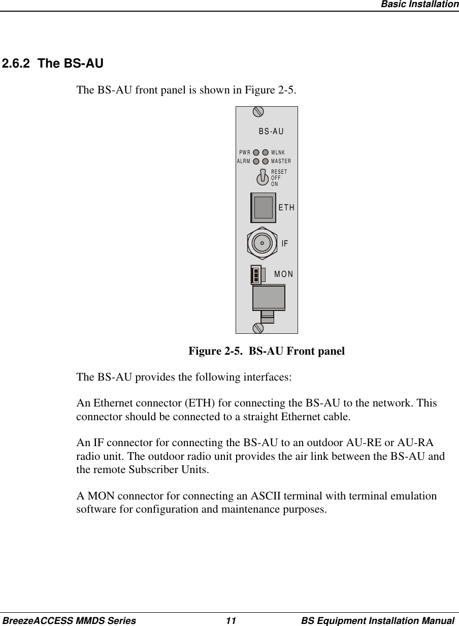
User manual 2
3.
Corrected user manual 1 of 2
4.
Corrected user manual 2 of 2
5.
New Sept 24 outdoor user manual
User manual 2
Navigation menu
Upload a User Manual
Namespaces
Wiki Guide
HTML
PDF
Info
Views
User Manual
Discussion / Help
Navigation