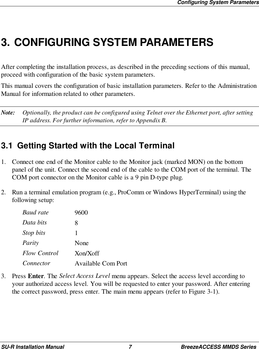
Alvarion Technologies SUR-MMDS1 MMDS Subscriber Unit User Manual installation manual
Alvarion Ltd. MMDS Subscriber Unit installation manual
UserManual.wiki
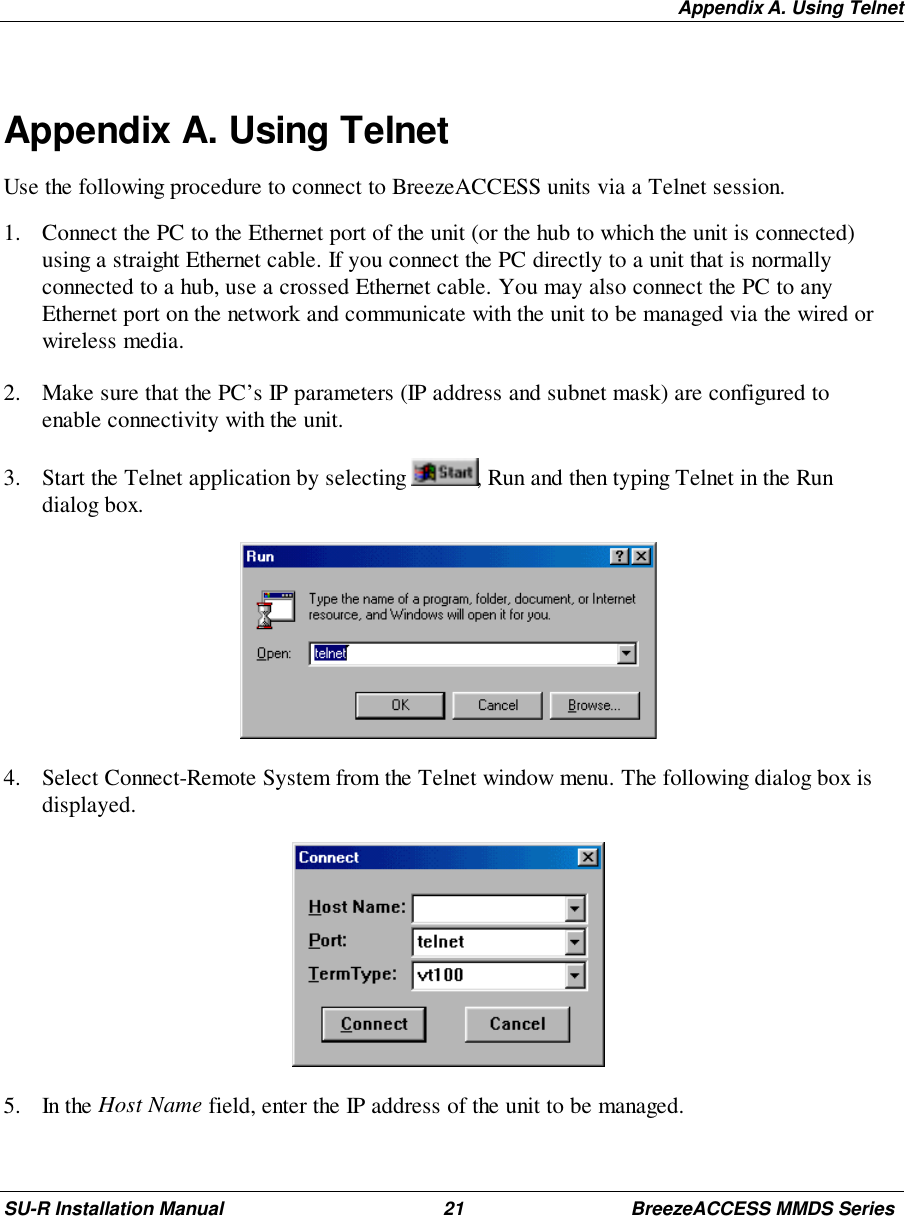
>
Alvarion Technologies
>
SUR MMDS1 User Manual
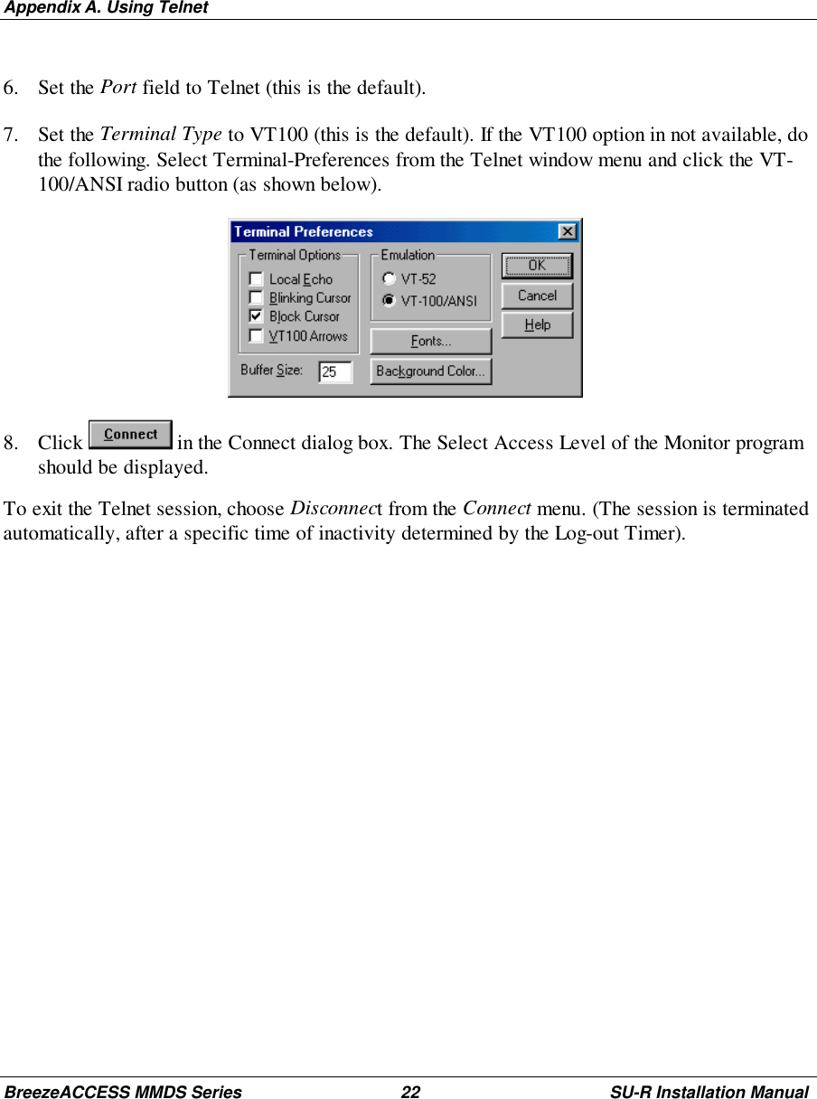
installation manual
Navigation menu
Upload a User Manual
Namespaces
Wiki Guide
HTML
PDF
Info
Views
User Manual
Discussion / Help
Navigation