Alvarion Technologies SUR-MMDS1 MMDS Subscriber Unit User Manual installation manual
Alvarion Ltd. MMDS Subscriber Unit installation manual
installation manual

FCCID: LKT-SUR-MMDS1
BreezeACCESS MMDS
Indoor Subscriber Units
SU-R Series
Installation
Manual
April, 2001
Cat. No. 213160

Front Matter
BreezeACCESS MMDS Series ii SU-R Installation Manual
© 2001 by BreezeCOM Ltd. All rights reserved.
No part of this publication may be reproduced in any material form without the written permission of the
copyright owner.
Trade Names
BreezeACCESS, BreezeNET, BreezeLINK, BreezeMANAGE, BreezeVIEW and BreezeWIZARD are
trade names of BreezeCOM Ltd. Other brand and product names are registered trademarks or
trademarks of their respective companies.
Statement of Conditions
The information contained in this manual is subject to change without notice. BreezeCOM shall not be
liable for errors contained herein or for incidental or consequential damages in connection with the
furnishing, performance, or use of this manual or equipment supplied with it.
Warranty
In the following warranty text, “the Company” shall mean:
• BreezeCOM Ltd., for products located outside the USA.
• BreezeCOM Inc., for products located in the USA.
This BreezeACCESS product is warranted against defects in material and workmanship for a period of
one year from date of purchase. During this warranty period the Company will, at its option, either
repair or replace products that prove to be defective.
For warranty service or repair, the product must be returned to a service facility designated by the
Company. Authorization to return products must be obtained prior to shipment. The buyer shall pay all
shipping charges to the Company and the Company shall pay shipping charges to return the product to the
buyer within the USA.
The Company warrants that the firmware designed by it for use with the unit will execute its
programming instructions when properly installed on the unit. The Company does not warrant that the
operation of the unit or firmware will be uninterrupted or error-free.
Limitation of Warranty
The foregoing warranty shall not apply to defects resulting from improper or inadequate maintenance by
the buyer, buyer supplied interfacing, unauthorized modification or misuse, operation outside of the
environmental specifications for the product, or improper site preparation or maintenance. No other
warranty is expressed or implied. The company specifically disclaims the implied warranties of
merchantability and fitness for any particular purpose.

Front Matter
SU-R Installation Manual iii BreezeACCESS MMDS Series
BreezeCOM shall not be liable to any person for any special or indirect damages, including, but not
limited to, loss of profits or revenues, loss of use or damage to any associated equipment, cost of
capital, cost of substitute products, facilities or services, downtime costs or claims resulting from any
cause whatsoever arising from or in any way connected with the manufacture, sale, handling, service,
repair, maintenance or use of the products. In no event shall the company’s liability exceed the purchase
price denoted on the invoice.
Electronic Emission Notice
This device complies with Part 15 of the FCC rules. Operation is subject to the following two
conditions:
1. This device may not cause harmful interference.
2. This device must accept any interference received, including interference that may cause undesired
operation.
FCC Radio Frequency Interference Statement
This equipment has been tested and found to comply with the limits for a class B digital device, pursuant
to Part 15 of the FCC rules. These limits are designed to provide reasonable protection against harmful
interference when the equipment is operated in a residential environment notwithstanding use in
commercial, business and industrial environments. This equipment generates, uses, and can radiate radio
frequency energy and, if not installed and used in accordance with the instruction manual, may cause
harmful interference to radio communications.
FCC Radiation Hazard Warning
To comply with FCC RF exposure requirements in section 1.1307, a minimum separation distance 20cm
(8 inches) is required between the antenna and all persons.
Information to User
Any changes or modifications of equipment not expressly approved by the manufacturer could void the
user’s authority to operate the equipment.
Safety Considerations
For the following safety considerations, “Instrument” means the BreezeACCESS Subscriber Unit
components.
Caution
To avoid shock, do not perform any servicing unless you are qualified to do so.

Front Matter
BreezeACCESS MMDS Series iv SU-R Installation Manual
Line Voltage
Before connecting this instrument to the power line, make sure that the voltage of the power source
matches the requirements of the instrument.
Radio
The instrument transmits radio energy during normal operation. To avoid possible harmful exposure to
this energy, do not stand or work for extended periods of time in front of its antenna. The long-term
characteristics or the possible physiological effects of Radio Frequency Electromagnetic fields have not
been yet fully investigated.
Table of Contents
BreezeACCESS MMDS Series v SU-R Installation Manual
Table of Contents
1. Introduction _______________________________________________________ 1
2. Basic Installation ___________________________________________________ 2
2.1 Packing List ___________________________________________________ 2
2.2 Other Required Items___________________________________________ 2
2.3 Installation Overview ___________________________________________ 3
2.4 Installation Guidelines __________________________________________ 3
2.5 Wall Mounting the Unit _________________________________________ 6
2.6 Connecting the Antenna _________________________________________ 6
2.7 Connecting the Unit to the Power Supply and to the CPE _____________ 6
3. Configuring System Parameters _______________________________________ 7
3.1 Getting Started with the Local Terminal ___________________________ 7
3.2 Configuring Basic Parameters____________________________________ 9
3.3 Reset Unit____________________________________________________ 11
4. Aligning the Antenna_______________________________________________ 12
4.1 Aligning the Antenna Using the LEDs_____________________________ 12
4.2 Aligning the Antenna Using the Site Survey Menu __________________ 12
5. Maximum Data Rate Configuration ___________________________________ 14
6. Verifying Proper Operation __________________________________________ 15
6.1 Checking the LEDs ____________________________________________ 15
6.2 Verifying the Ethernet Connection _______________________________ 15
6.3 Verifying Data Connectivity_____________________________________ 16
6.4 Verifying Telephone Connectivity (units with voice support)__________ 16
7. Specifications _____________________________________________________ 17

Table of Contents
BreezeACCESS MMDS Series vi SU-R Installation Manual
7.1 Radio________________________________________________________ 17
7.2 Data Communication___________________________________________ 17
7.3 Voice Communication (units with voice support)____________________ 17
7.4 Configuration and Management _________________________________ 18
7.5 Interfaces ____________________________________________________ 18
7.6 Electrical ____________________________________________________ 18
7.7 Mechanical___________________________________________________ 18
7.8 Environmental ________________________________________________ 19
7.9 Standards Compliance, General _________________________________ 19
Appendix A. Using Telnet_____________________________________ 21
Appendix B. MMDS channels & Frequencies ____________ 23
Appendix C. Basic Parameters_______________________________ 25

Introduction
SU-R Installation Manual 1 BreezeACCESS MMDS Series
1. INTRODUCTION
This manual describes installation guidelines for BreezeACCESS MMDS SU-R Subscriber Units.
The BreezeACCESS Broadband Wireless Access system allows access service providers to
provide high-speed IP connectivity services to their subscribers. To support IP-based services
effectively BreezeACCESS systems employ wireless packet data switching technology.
The BreezeACCESS MMDS line of products uses Frequency Hopping Spread Spectrum radios
that operate in Time Division Duplex (TDD) mode in the 2.500GHz – 2.686GHz frequency
range.
The SU-R-MMDS line of Subscriber Units comprises compact units that are designed for indoor
installation. SU-R units are available in several models differing from each other in the type of
supported data networks and availability of voice services as follows:
• SU-R-8D units support up to 8 Ethernet workstations / PCs (8 MAC addresses).
• SU-R-BD units provide a full bridge functionality supporting up to 512 MAC addresses.
• SU-R-8D1V support up to 8 Ethernet workstations / PCs and have an interface to a standard
telephone set.
SU-R-MMDS units are available either with an indoor wall/window mountable 7 dBi UNI-7
antenna (-A7 models) or with an adapter for an external separate antenna.
Note: The information contained in this manual is applicable to BreezeACCESS SU-R-MMDS
units with software release 3.0 and up.

Basic Installation
BreezeACCESS MMDS Series 2 SU-R Installation Manual
2. BASIC INSTALLATION
2.1 Packing List
The SU-R units are shipped with the following units and accessories. The exact packing list
varies depending on system configuration and ordered equipment.
• SU-R unit
• An SMA adapter
• A 7 dBi UNI-7 antenna eith a 3 m cable and a wall mounting kit (with A7 models only)
• A power supply
• Wall mounting kit for the SU-R unit (two anchors and screws)
• An Ethernet cable (straight)
2.2 Other Required Items
The following items must be available for the installation
• Antenna*and RF cable*for models that are supplied without an antenna
• An Ethernet cable (crossed) if the unit should be connected to a hub (the straight Ethernet
cable supplied with the unit is intended for connecting it directly to a PC or to a hub’s uplink
port)
• A PC with terminal emulation program
• A monitor cable* for configuration and testing via the Monitor interface
• Installation tools and materials
Items marked with an asterisk (*) are available from BreezeCOM.

Basic Installation
SU-R Installation Manual 3 BreezeACCESS MMDS Series
2.3 Installation Overview
Standard installation involves the following steps:
1. Verify that all components of the packing list, described in Section 2.1, are intact and verify
availability of the required items listed in Section 2.2.
2. Install the unit and antenna in optimal locations as described in Sections 2.4 and 2.5 and in
the instructions supplied with the antenna.
Note: To avoid drilling unnecessary holes, it is recommended to verify good connectivity with the
base station prior to drilling holes in the locations intended for the SU-R unit and/or the
indoor antenna.
3. Connect the antenna to the unit as described in Section 2.6.
4. Connect the power supply and the user’s equipment to the unit as described in Section 2.7 .
5. Configure the basic system parameters as described in Section 3.
6. Align the antenna for optimal connectivity and configure the Maximum Data Rate if
applicable, as described in Chapters 4 and 5.
7. Check the functionality of the unit as described in Chapter 6.
2.4 Installation Guidelines
This section describes the installation guidelines and the various considerations that must be
taken into account when planning the installation.
2.4.1 Location of the Unit
• The unit can be placed on a desktop or a shelf, or can be attached to a wall.
• The unit should be installed as neat as possible to the antenna (-A7 models). The RF cable
connecting the unit to the antenna should be as short as possible to guarantee minimum power
loss.

Basic Installation
BreezeACCESS MMDS Series 4 SU-R Installation Manual
• Keep the units well away from sources of heat, such as radiators, air-conditioners, etc.
2.4.2 Location of the Antenna
• Any physical object in the path between two units can cause signal attenuation. Common
obstructions are buildings and trees. If a unit’s antenna is installed indoors, the walls and/or
windows between the two sites are physical obstructions. If the antenna is positioned
outdoors, any buildings or other physical structure such as trees, mountains or other natural
geographic features higher than the antenna and situated in the path between the two sites can
constitute obstructions.
• Install indoor antennas as close as possible to a window (or wall if a window is not
accessible) facing the required direction. The UNI-7 antenna may also be attached to a fixed
window. Avoid metal obstacles such as metal window frames or metal film anti-glare
windows in the transmission path. Install outdoor antennas high enough to avoid any obstacles,
which may block the signal.
• Position the antennas clear of metal furniture and away from moving metal objects such as
metal fans or doors.
2.4.3 Antenna Diversity
In applications where no multipath propagation is expected, a single antenna is sufficient to ensure
good performance levels. However, in cases where multipath propagation exists, BreezeCOM
recommends that two antennas be used. This takes advantage of space diversity capabilities. By
using two antennas per unit, the system can select the best antenna on a per-packet basis (every
several milliseconds).
Multipath propagation is to be expected when there are potential reflectors between the Access
Unit and Subscriber Units. These reflectors may be buildings or moving objects such as airplanes
and motor vehicles. If this is the case, the radio signal does not travel in a straight line, but is
reflected or deflected off of the object, creating multiple propagation paths.
When installing a single antenna, modify the transmit diversity option to either antenna 1 or
antenna 2, according to the antenna being used.
2.4.4 Antenna Polarization
Antenna polarization must be the same at either end of the link. In most applications, the preferred
orientation is vertical polarization. Above-ground propagation of the signal is better when it is
polarized vertically. To verify antenna polarization, refer to the assembly instructions supplied

Basic Installation
SU-R Installation Manual 5 BreezeACCESS MMDS Series
with the antenna set. For the detached UNI-7 antenna (A7 model) follow the instructions included
with the antenna.
2.4.5 Antenna Seal
When using outdoor antennas, you must seal the antenna connectors against rain. Otherwise, the
antennas are not suitable for use in outdoor installations.
2.4.6 Lightning Protection
Lightning protection is designed to protect people, property and equipment by providing a path to
ground for the lightning’s energy. The lightning arrestor diverts the strike energy to ground through
a deliberate and controlled path instead of allowing it to choose a random path. Lightning
protection for a building is more forgiving than protection of electronic devices. A building can
withstand up to 100,000 volts, but electronic equipment may be damaged by just a few volts.
Lightning protection entails connecting an antenna discharge unit (also called an arrestor) to each
cable as close as possible to the point where it enters the building. It also entails proper grounding
of the arrestors and of the antenna mast (if the antenna is connected to one).
The lightning arrestor should be installed and grounded at the point where the cable enters the
building. The arrestor is connected to the unit at one end and to the antenna at the other end.
The professional installer you choose must be knowledgeable about lightning protection. The
installer must install the lightning protector in a way that maximizes lightning protection.
AL 1 Lightning Arrestor - Part No. 872905 5 ft (1.5m), “N” Male to “N” Female is available from
BreezeCOM.
Note: Detached outdoors antennas should be installed ONLY by experienced antenna installation
professionals who are familiar with local building and safety codes and, wherever
applicable, are licensed by the appropriate government regulatory authorities.
Failure to do so may void the BreezeACCESS Product Warranty and may expose the end
user to legal and financial liabilities. BreezeCOM and its resellers or distributors are not
liable for injury, damage or violation of government regulations associated with the
installation of detached antennas.

Basic Installation
BreezeACCESS MMDS Series 6 SU-R Installation Manual
2.5 Wall Mounting the Unit
Note: To avoid drilling unnecessary holes, it is recommended to verify connectivity with the base
station prior to drilling holes in the locations intended for the SU-R unit and/or the indoor
antenna.
The drill template on the packaging box can be used to mark the locations of the screws on the
wall (drill right through the markings on the drill template).
After insertion of the anchors and screws, hang-on the unit on the two screws with the bottom
panel (the side with the connectors) facing downward.
2.6 Connecting the Antenna
1. Connect the special adapter to antenna port 1 (marked 1) on the side of the unit. Push the
adapter carefully into the hole using the alignment markings on the adapter and the unit, and
turn it 180 degrees to firmly lock it.
2. Connect the antenna cable to the adapter. If you use a heavy cable, secure the cable so as to
prevent applying excessive force on the adapter and connector.
2.7 Connecting the Unit to the Power Supply and to the CPE
The unit operates on a power input of 5V DC, supplied by the power transformer included with
the unit.
1. Plug the output jack of the power transformer into the DC input jack (marked DC IN)
located on the bottom panel of the unit.
2. Connect the supplied universal power transformer to a power outlet - 110/ 220VAC.
3. Use a straight Ethernet 10BaseT cable to connect the Ethernet port (marked ETH) to a PC or
to a hub’s uplink port. Use a crossed cable to connect to a hub.
4. For units with voice support, use the standard cable connected to the telephone set to
connect the telephone to the telephone port (marked TEL).

Configuring System Parameters
SU-R Installation Manual 7 BreezeACCESS MMDS Series
3. CONFIGURING SYSTEM PARAMETERS
After completing the installation process, as described in the preceding sections of this manual,
proceed with configuration of the basic system parameters.
This manual covers the configuration of basic installation parameters. Refer to the Administration
Manual for information related to other parameters.
Note: Optionally, the product can be configured using Telnet over the Ethernet port, after setting
IP address. For further information, refer to Appendix B.
3.1 Getting Started with the Local Terminal
1. Connect one end of the Monitor cable to the Monitor jack (marked MON) on the bottom
panel of the unit. Connect the second end of the cable to the COM port of the terminal. The
COM port connector on the Monitor cable is a 9 pin D-type plug.
2. Run a terminal emulation program (e.g., ProComm or Windows HyperTerminal) using the
following setup:
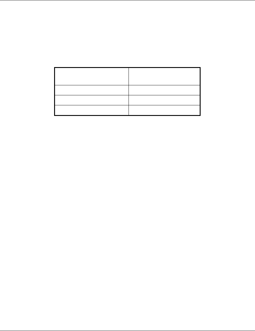
Baud rate 9600
Data bits 8
Stop bits 1
Parity None
Flow Control Xon/Xoff
Connector Available Com Port
3. Press Enter. The Select Access Level menu appears. Select the access level according to
your authorized access level. You will be requested to enter your password. After entering
the correct password, press enter. The main menu appears (refer to Figure 3-1).

Configuring System Parameters
BreezeACCESS MMDS Series 8 SU-R Installation Manual
BreezeACCESS/SU-R
Official Release Version – 3.0.2
Release Date: Mon Oct 23 21:05:08 2000
Main Menu
=====================
1 – Info Screens
2 – Unit Control
3 – Basic Configuration
4 – Site Survey
5 – Advanced Configuration
>>>
Figure 3-1. Main Menu
The appearance of the displayed Main Menu varies in accordance with the access level.
• For users with read only access rights, only the Info Screens option is displayed. Users with
this access level cannot access the Unit Control, Basic Configuration, Site Survey and
Advanced Configuration menus.
• For users with Installer access rights, the first four menu items (Info Screens, Unit Control,
Basic Configuration and Site Survey) are displayed. Users with this access level cannot
access the Advanced Configuration menu.
• For users with Administrator access rights, the full Main Menu will be displayed. These users
can access all the menu items.
Unit Type
Software
Version No.

Configuring System Parameters
SU-R Installation Manual 9 BreezeACCESS MMDS Series
Operate the monitor program as follows:
• Type an option number to open/activate the option. You may need to press the Enter key in
some cases.
• Press the Esc key to exit a menu or an option.
• You can log-out and exit the monitor program from the Main Menu by simultaneously
pressing the Ctrl and X keys. The session is terminated automatically, after a specific time of
inactivity determined by the Log-out Timer. The default value for the Log-out Timer is 5
minutes.
• Reset the unit after making configuration changes for the new values to take effect.
• You can view the current parameters’ configuration by selecting 1 in the Main Menu to
Access the Info Screens menu, and than selecting 2 in the Info Screens menu to view the Basic
Configuration parameters.
3.2 Configuring Basic Parameters
The following system parameters must be configured for each specific installation:
• ESSID
• IP Parameters: DHCP Client and/or IP Address, Subnet Mask and Default Gateway Address
• Flexible Hopping Definition
• Transmit Antenna
Note: You must select Reset Unit in the Unit Control menu for the changes to take effect.
Subscriber Units should be configured after the applicable Access Unit is operational.
See Appendix C for more details on the basic parameters.

Configuring System Parameters
BreezeACCESS MMDS Series 10 SU-R Installation Manual
1. From the main menu, type 3 to access the Basic Configuration menu.
2. From the Basic Configuration menu, type 4 to access the ESSID selection screen. Enter the
required ESSID.
3. Type D to access the DHCP Client menu. Type 1 to access the DHCP Options menu and
select the required option. If the selected option was other than Disable, type 2 to access the
Access to DHCP menu and select the required option.. If the DHCP Only option was
selected, go to step 7. Otherwise (if either the Disable or Automatic options were selected),
perform steps 4-6.
4. Type 1 to access the IP Address selection screen. Enter the required IP address.
5. Type 2 to access the Subnet Mask selection screen. Enter the required subnet mask.
6. Type 3 to access the Default Gateway Address selection screen. Enter the required default
gateway address.
7. Type F to access the Flexible Hopping Definition menu. Use the Add/Remove Channels or
the Add/Remove Frequencies screen to define the channels/frequencies to be used. See
Appendix B for a list of the standard channels and frequencies.
8. Type G to access the Transmit Antenna selection screen. Enter the required selection. For
SU-R units with a single antenna connected to antenna port 1, select 1 - use antenna # 1.

Configuring System Parameters
SU-R Installation Manual 11 BreezeACCESS MMDS Series
3.3 Reset Unit
1. From the main menu, type 2 to access the Unit Control menu.
2. Type 1 to access the Reset Unit menu. Type 1 to reset the unit so that new configuration
settings are applied.
Note: Should you make any mistakes during configuration or encounter any problems associated
with system configuration parameters, you may configure the unit back to the factory
defaults, as follows:
Type 2 in the Unit Control menu to access the Set Factory Defaults menu. Type in 2 (Set
Factory defaults-Full) to load the default values. Reset the unit for the factory defaults
values to take effect.

Aligning the Antenna
BreezeACCESS MMDS Series 12 SU-R Installation Manual
4. ALIGNING THE ANTENNA
When using high gain antennas with a narrow beam width, an alignment procedure is necessary in
order to optimize the quality of the link with the Access Unit.
For a Subscriber Unit with a directional antenna, you can either use the LED indicators on the
front panel of the unit or view the Received Signal Strength Indication (RSSI) using the monitor
program. In most installations, alignment using the LEDs is sufficient. The RSSI reading can be
used when finer alignment is required (see 3.2).
Note: Antenna alignment of the Subscriber Unit is possible only after the Access Unit you wish to
associate with is operational and the basic parameters were properly configured as
described in Section 3.2.
4.1 Aligning the Antenna Using the LEDs
1. The H (high), M (medium) and L (low) LEDs on the front panrel of the unit indicate the
quality of the link. The higher the number of illuminated LEDs the better is the quality of the
link.
2. Rotate the antenna left and/or right until you reach the point of maximal signal quality
reading on the H, M and L LEDs. Make sure that at all times, the front of the antenna faces
the general direction of the Access Unit. In some cases, e.g. when the unit is very close to
the base station you may need to tilt the antenna upward or downward.
3. For proper operation, at least one (L) LED should be illuminated. If this is not possible,
improve the link quality by placing the antenna at a higher point or in a different location.
4. After the antenna is optimally aligned, secure the antenna to guarantee that it will remain in
the selected position.
4.2 Aligning the Antenna Using the Site Survey Menu
1. Start the Monitor program as described in Section 3.1.

Aligning the Antenna
SU-R Installation Manual 13 BreezeACCESS MMDS Series
2. From the main menu, type 4 to access the Site Survey menu. Type 4 to start the Continuous
Link Quality Display. Each line in the display includes the number of frames that were
received since the last measurement (total Rx) and the average RSSI for these frames.
3. Rotate the antenna left and/or right (or tilt it upward/downward) until you reach the point of
maximum RSSI reading. Make sure that at all times, the front of the antenna faces the general
direction of the Base Station.
4. For proper operation, the RSSI reading should be at least 38 units. When the maximum
reading is less than 43 units, try to improve it by placing the antenna at a higher point or in a
different location. For best performance it is recommended that the RSSI be higher than 65.
5. Press the Esc key to stop the test.
6. Secure the antenna to guarantee that it will remain in the selected position.
Maximum Data Rate Configuration
BreezeACCESS MMDS Series 14 SU-R Installation Manual
5. MAXIMUM DATA RATE CONFIGURATION
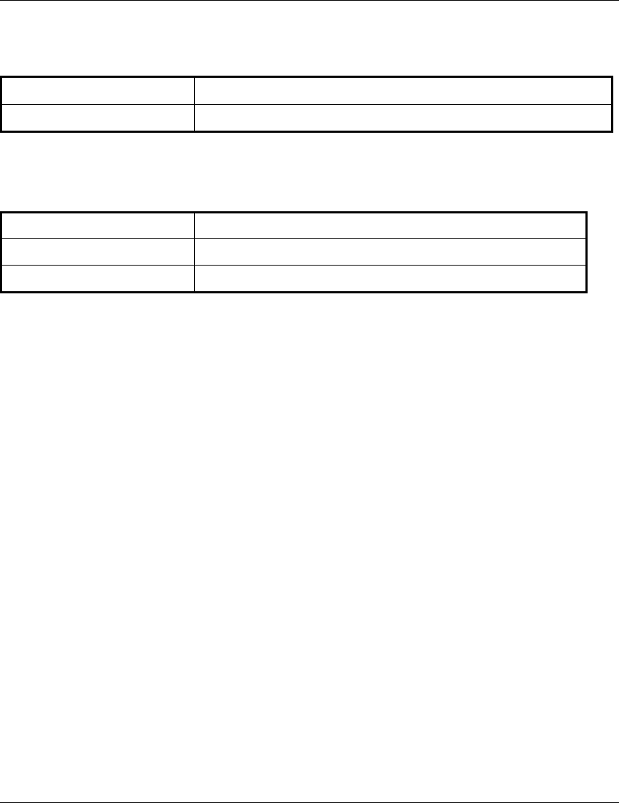
1. If the average RSSI reading using the Continuous Link Quality Display (see Section 4.1) is
lower than 65, the unit should be configured in accordance with the following table:
RSSI Recommended
Maximum Data Rate
RSSI > 65 3Mbps
53 < RSSI < 65 2Mbps
RSSI < 53 1Mbps
2. From the main menu, type 3 to access the Basic Configuration menu. Type 5 to access the
Maximum Data Rate menu.
• Type 3 (3Mbps) if the RSSI reading is higher than 65 units.
• Type 2 (2Mbps) if the RSSI reading is between 53 to 65 units.
• Type 1 (1Mbps) if the RSSI reading is lower than 53 units.
3. Reset the unit for the new configuration to become effective
See Appendix C for more details on the Maximum Data Rate parameter.
Verifying Proper Operation
SU-R Installation Manual 15 BreezeACCESS MMDS Series
6. VERIFYING PROPER OPERATION
6.1 Checking the LEDs
After completing the installation, the system starts operation. To verify proper operation, view the
LEDs located on the front panel of the unit. Table 6-1 lists the various LED states.
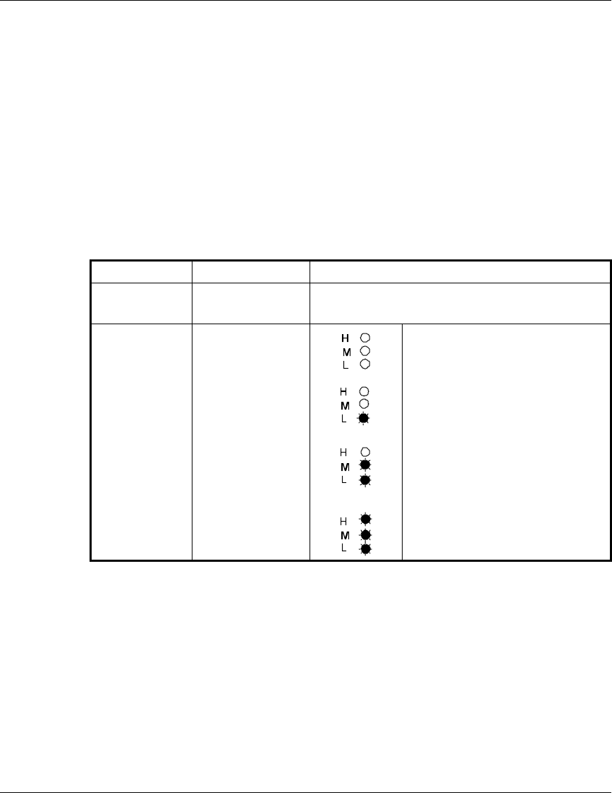
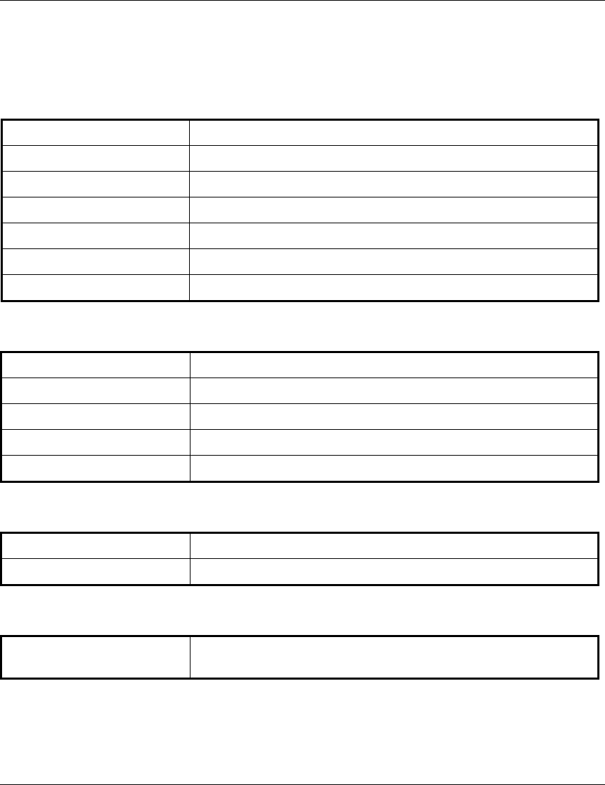
Table 6-1. SU LEDs
Name Description Functionality
POWER Power supply On – After successful power up
Off – Power off
H, M, L Quality of
received RF
signal
Very low quality reception or not
synchronized with Access Unit.
Low quality reception (usually
enabling 1Mbps traffic).
Medium quality reception (usually
enabling 2 Mbps traffic).
High quality reception (usually
enabling 3 Mbps traffic).
6.2 Verifying the Ethernet Connection
Once you have connected the unit to an Ethernet outlet, verify that the Ethernet
Integrity indicator (the yellow LED embedded in the Ethernet connector) is on,
indicating that the unit is connected to an Ethernet segment. The Ethernet Activity
indicator (the green embedded LED) should blink whenever the unit receives or
transmit traffic on the Ethernet port.

Verifying Proper Operation
BreezeACCESS MMDS Series 16 SU-R Installation Manual
6.3 Verifying Data Connectivity
From the user’s PC or from a portable PC connected to the unit, ping the Access Terminal, or try
to connect to the Internet.
6.4 Verifying Telephone Connectivity (units with voice support)
To verify correct operation of the telephone, a test telephone with the default telephony
parameters and a known IP address should be connected to the system (the location of the test
telephone is determined by the system administrator).
Perform the following steps to verify telephone connectivity:
1. Use IP dialing to call the test telephone: dial * followed by the 12-digit IP address of the test
telephone. Verify connectivity. During the conversation, verify that other party has your IP
address.
2. After terminating the call, the other party should use the test telephone to call your IP
address and verify that the telephone, including the ringing circuits, functions properly.
Specifications
SU-R Installation Manual 17 BreezeACCESS MMDS Series
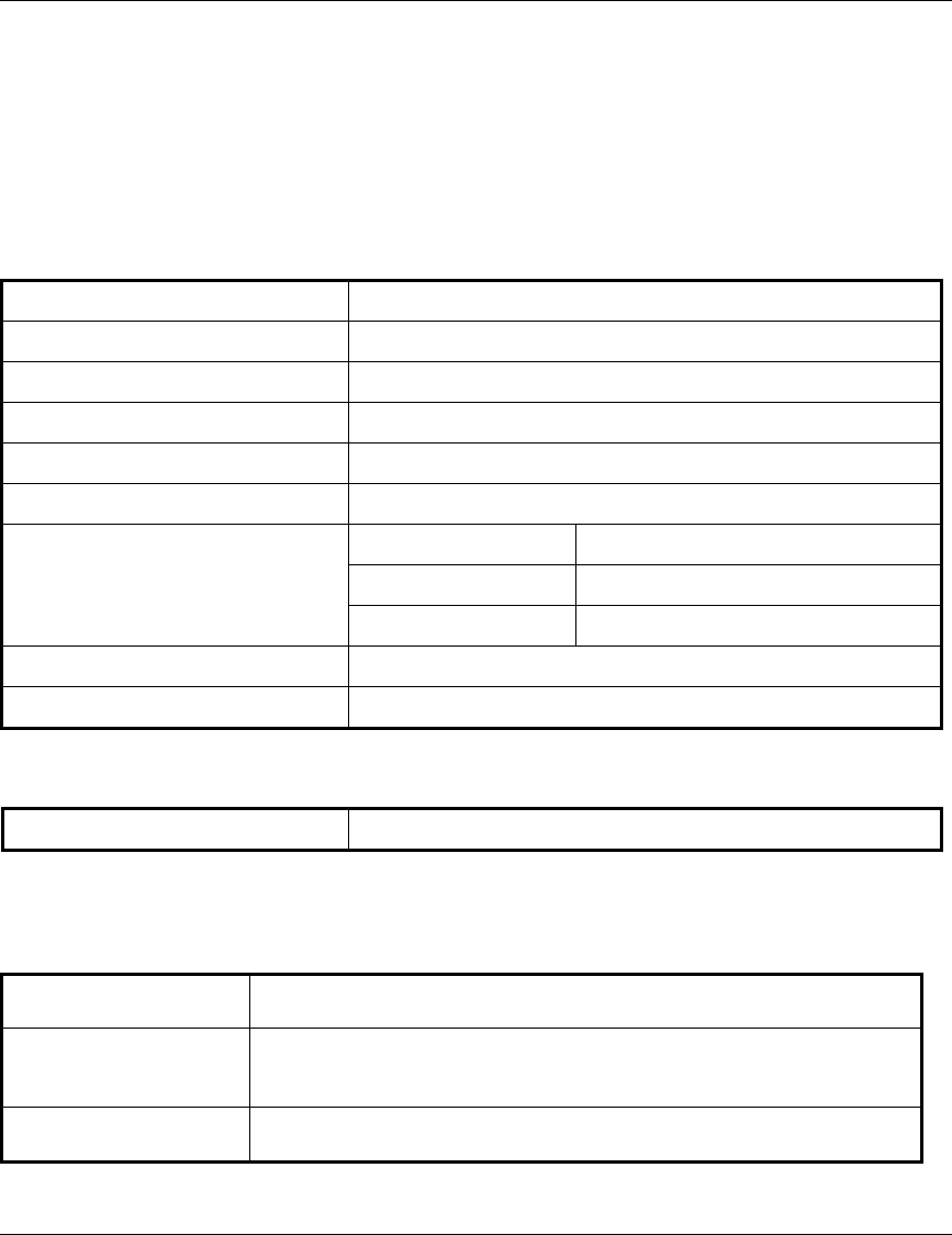
7. SPECIFICATIONS
7.1 Radio
Frequency 2.500 – 2.686 GHz
Radio Access Method FH-CDMA or TDMA
Operation Mode Time Division Duplex
Channel Bandwidth 2 MHz
Output Power (at antenna port) 28 dBm typical. (can be reduced to 17 dBm-SW controlled)
Antenna Gain (UNI-7) 7 dBi (including 3 m cable loss)
Sensitivity 1Mbps -91
(dBm at antenna port, BER 1E10-6) 2Mbps -83
3Mbps -75
Data Rate 3Mbps max
Modulation Multilevel GFSK
7.2 Data Communication
Standard Compliance IEEE 802.3 CSMA/CD
7.3 Voice Communication (units with voice support)
Protocol H.323 Voice over IP compliant
Compression G.723 6.3 Kbps compression, G.729 8 Kbps compression,
G.711 64 Kbps transparent
Echo Cancellation G.168, G.131
Specifications
BreezeACCESS MMDS Series 18 SU-R Installation Manual
7.4 Configuration and Management
Local Management Via MON port, Monitor program using terminal emulation
Remote Management SNMP, Telnet, TFTP
Remote Management Access From Wired LAN, Wireless Link
SNMP Agents MIB II, Bridge MIB, Private MIBs
Accounting RADIUS compatible client
Security Authentication and filtering
Software upgrade TFTP download
7.5 Interfaces
RF (Antenna) 2 x OCX jacks (A special OCX to SMA adapter is available)
Ethernet 10Base-T (RJ-45)
Telephone (units with voice) RJ-11 standard Plain Old Telephone System (POTS) interface
Monitor 3-pin low profile
Power DC socket for a power transformer
7.6 Electrical
External power Supply 100-250 VAC, 50-60 Hz, 0.5 A
Input voltage 5VDC
7.7 Mechanical
Without antenna and power
supply
Specifications
SU-R Installation Manual 19 BreezeACCESS MMDS Series
7.8 Environmental
Operating Temperature 0°C to 40°C
Operating Humidity 5%-95% non condensing
7.9 Standards Compliance, General
EMC FCC part 15, FCC part 21, EN 300 826
Safety UL 1950, EN 60950
Environmental ETS 300 019
Appendix A. Using Telnet
SU-R Installation Manual 21 BreezeACCESS MMDS Series
Appendix A. Using Telnet
Use the following procedure to connect to BreezeACCESS units via a Telnet session.
1. Connect the PC to the Ethernet port of the unit (or the hub to which the unit is connected)
using a straight Ethernet cable. If you connect the PC directly to a unit that is normally
connected to a hub, use a crossed Ethernet cable. You may also connect the PC to any
Ethernet port on the network and communicate with the unit to be managed via the wired or
wireless media.
2. Make sure that the PC’s IP parameters (IP address and subnet mask) are configured to
enable connectivity with the unit.
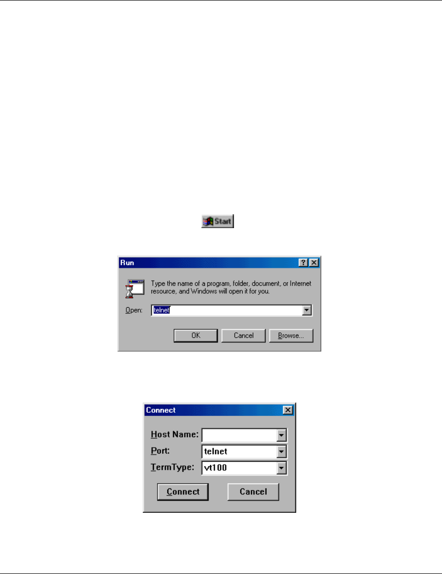
3. Start the Telnet application by selecting , Run and then typing Telnet in the Run
dialog box.
4. Select Connect-Remote System from the Telnet window menu. The following dialog box is
displayed.
5. In the Host Name field, enter the IP address of the unit to be managed.
Appendix A. Using Telnet
BreezeACCESS MMDS Series 22 SU-R Installation Manual
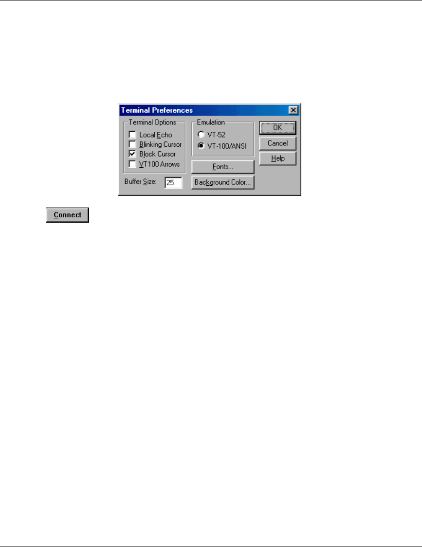
6. Set the Port field to Telnet (this is the default).
7. Set the Terminal Type to VT100 (this is the default). If the VT100 option in not available, do
the following. Select Terminal-Preferences from the Telnet window menu and click the VT-
100/ANSI radio button (as shown below).
8. Click in the Connect dialog box. The Select Access Level of the Monitor program
should be displayed.
To exit the Telnet session, choose Disconnect from the Connect menu. (The session is terminated
automatically, after a specific time of inactivity determined by the Log-out Timer).

Appendix B. MMDS Channels and Frequencies
SU-R Installation Manual 23 BreezeACCESS MMDS Series
Appendix B. MMDS channels & Frequencies
Channel
Name Frequency
Band (MHz) Low
Frequency
(MHz)
High
Frequency
(MHz)
A1 2500 - 2506 2501.5 2504.5
B1 2506 - 2512 2507.5 2510.5
A2 2512 - 2518 2513.5 2516.5
B2 2518 - 2524 2519.5 2522.5
A3 2524 - 2530 2525.5 2528.5
B3 2530 - 2536 2531.5 2534.5
A4 2536 - 2542 2537.5 2540.5
B4 2542 - 2548 2543.5 2546.5
C1 2548 - 2554 2549.5 2552.5
D1 2554 - 2560 2555.5 2558.5
C2 2560 - 2566 2561.5 2564.5
D2 2566 - 2572 2567.5 2570.5
C3 2572 - 2578 2573.5 2576.5
D3 2578 - 2584 2579.5 2582.5
C4 2584 - 2590 2585.5 2588.5
D4 2590 - 2596 2591.5 2594.5
E1 2596 - 2602 2597.5 2600.5

Appendix B. MMDS Channels and Frequencies
BreezeACCESS MMDS Series 24 SU-R Installation Manual
Channel
Name Frequency
Band (MHz) Low
Frequency
(MHz)
High
Frequency
(MHz)
F1 2602 - 2608 2603.5 2606.5
E2 2608 - 2614 2609.5 2612.5
F2 2614 - 2620 2615.5 2618.5
E3 2620 - 2626 2621.5 2624.5
F3 2626 - 2632 2627.5 2630.5
E4 2632 - 2638 2633.5 2636.5
F4 2638 - 2644 2639.5 2642.5
G1 2644 - 2650 2645.5 2648.5
H1 2650 - 2656 2651.5 2654.5
G2 2656 - 2662 2657.5 2660.5
H2 2662 - 2668 2663.5 2666.5
G3 2668 - 2674 2669.5 2672.5
H3 2674 - 2680 2675.5 2678.5
G4 2680 - 2686 2681.5 2684.5

Appendix C. Basic Parameters
SU-R Installation Manual 25 BreezeACCESS MMDS Series
Appendix C. Basic Parameters
• IP Address – Displays the current IP address of the unit and allows entry of a new IP address
(4 x 3 digit octets, separated by dots). The default IP Address is 010.000.000.001.
• Subnet Mask – Displays the current subnet mask of the unit and allows entry of a new
subnet mask (4 x 3 digit octets, separated by dots). The default mask is 255.000.000.000.
• Default Gateway Address – Displays the current address of the default gateway of the unit
and allows entry of a new default gateway address (4 x 3 digit octets, separated by dots). The
default gateway address is 000.000.000.000.
• DHCP Client
⇒ DHCP Options – Displays the current status of the DHCP (Dynamic Host Configuration
Protocol) support, and allows selecting a new operation mode. The available options are:
∗ Disable – Use manual procedure for configuring the IP parameters.
∗ DHCP Only – Search for a DHCP Server and obtain the IP parameters from it (IP
Address, Subnet Mask and Default Gateway Address).
∗ Automatic – Search for a DHCP Server for configuration of the IP parameters. If a
DHCP Server is not found within approximately 40 seconds, use the currently
configured IP parameters.
The default is Disable.
⇒ Access to DHCP - To define the port through which the unit is allowed to communicate
with a DHCP server. The options are the following:
∗ From Wlan Only
∗ From Ethernet Only
∗ From Both Ethernet & Wlan
The default for an Access Unit is From Ethernet Only. The default for a Subscriber Unit is
From Wlan Only.
• ESS ID – The ESSID (Extended Service Set ID) of the unit (up to 32 printable ASCII
characters). The ESSID is a string used to identify a wireless network. It prevents the
unintentional merging of two co-located wireless networks. An SU can only associate with an
AU that has an identical ESSID. Use different ESSIDs to segment the wireless access network
and add security to your network. The default value is ESSID1.
Appendix C. Basic Parameters
BreezeACCESS MMDS Series 26 SU-R Installation Manual
Note: The ESSID string is case-sensitive.
• Maximum Data Rate – Displays the current maximum data rate, and allows entry of a new
value for the maximum data rate.
BreezeACCESS units operate at 1 Mbps, 2 Mbps or 3 Mbps. Under certain conditions
(compatibility reasons or range/speed trade-off), you may decide to limit the use of higher
rates. If the quality of the link is not good enough, it is recommended to decrease the value of
these parameters (the higher the date rate, the higher the error rate). Otherwise, there is a high
probability that the unit will have to retransmit many frames several times before temporarily
reducing the data rate. A high number of retransmissions reduces the overall throughput for
the selected SU as well as for all the other SUs served by the same AU.
The link quality can be estimated based on the RSSI measurement using the Continuous Link
Quality Display in the SU. If the measured RSSI is less than a certain threshold, it is
recommended to decrease the Maximum Data Rate of the SU in accordance with the following
table:
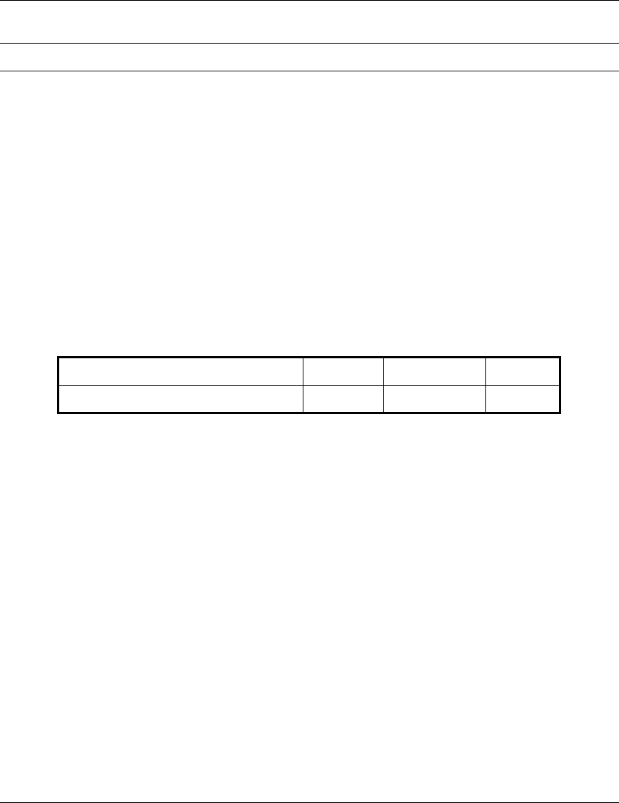
Recommended Maximum Data Rate 3Mbps 2Mbps 1Mbps
BreezeACCESS MMDS SU-I/ID RSSI>65 53<RSSI<65 RSSI<53
The default value is 3 Mbps. Allowed values are 1, 2 or 3 Mbps.
The AU learns the Maximum Data Rate used by each SU during the association process, and
uses this rate for transmissions to the specific SU.
• Flexible Hopping Definition – Allows adding and removing frequencies to the list of
hopping frequencies; displays the selected hopping frequencies and the current hopping
sequence (based on the previous selections made before the last Reset). The new selections
will come into effect only after the next Reset.
The Flexible Hopping is based on using the standard MMDS 6MHz channels and frequencies.
See Appendix C for a detailed list of the standard channels, as well as the frequency band and
the hopping frequencies for each of these channels.
The Flexible Hopping menu includes the following options, allowing adding/removing
standard MMDS channels or adding/removing discrete standard hopping frequencies.

Appendix C. Basic Parameters
SU-R Installation Manual 27 BreezeACCESS MMDS Series
⇒ Add Frequencies – Allows adding discrete hopping frequencies or frequency ranges.
Enter a list of frequencies and/or frequency ranges to be added, e.g. 2501.500,2507.500-
2519.500, 2525.500.Use a comma to separate between entries (no spaces). The allowed
entries are from 2500 to 2688 in steps of 0.5MHz. The frequencies (either the start and
stop frequencies of a range or discrete frequencies) can be in the following formats:
MHz Resolution, e.g. 2520
kHz resolution, e.g. 2501.000,2505.500 (you must enter 3 digits after the dot).
The minimal channel spacing between frequencies is 3MHz. When entering a range, this will
be the default channel spacing (e.g. for the range 2510-2516 the hopping frequencies will
be 2510, 2513 and 2516 MHz).
It is recommended to use the standard MMDS frequencies. See Appendix C for a list of the
standard MMDS frequencies.
⇒ Remove Frequencies - Allows removing frequencies from the existing list. Enter a list of
frequencies and/or frequency ranges to be removed, using the same guidelines as in Add
Frequencies above
⇒ Add Channels – Allows defining a new list of channels or adding channels to an existing
list. Enter a list of channels to be added, e.g. A1,B3,D2. Use a comma to separate
between entries (no spaces). See Appendix C for a list of the channels and the hopping
frequencies for each of the channels.
⇒ Remove Channels – Allows removing channels from existing list. Enter a list of channels
to be removed, using the same guidelines as in Add Channels above.
⇒ Erase All – Allows erasing all the entries from the list.
⇒ Show Flexible Hopping Parameters – Allows viewing the following information:
∗ An updated list of the defined sub-bands and discrete frequencies to become effective
after the next Reset. A sub-band is defined by the first and last hopping frequency in a
series of consecutive frequencies, with 3MHz separation between frequencies.
∗ An updated list of all the hopping frequencies to be used after the next Reset.
∗ The current sequence of operational hopping frequencies
• Transmit Antenna – Displays which antennas are used for transmission. SU-R units support
transmit antenna diversity (2 antennas). During reception, a BreezeACCESS unit that is
connected to two antennas dynamically selects the antenna where reception is optimal. In
contrast, if the transmit antenna diversity is enabled, the unit selects the antenna from which it

Appendix C. Basic Parameters
BreezeACCESS MMDS Series 28 SU-R Installation Manual
will transmit before the actual transmission. It usually uses the antenna last used for
successful transmission. In installations where a model that can support antenna diversity is
connected to a single antenna, Transmit Antenna Diversity should be configured to transmit
only from that single antenna. Available selections are:
⇒ Use Two Antennas
⇒ Use Antenna No. 1
⇒ Use Antenna No. 2
The default selection is Use Antenna No. 1 for SU-R units where a single antenna is
connected to antenna port 1.

SU-R Installation Manual 29 BreezeACCESS MMDS Series