Alvarion Technologies VL-900 BreezeACCESS VL 900MHz User Manual BreezeACCESS VL System Manual
Alvarion Technologies Ltd. BreezeACCESS VL 900MHz BreezeACCESS VL System Manual
UserManual.wiki
>
Alvarion Technologies
>
VL 900 User Manual
Manual
Navigation menu
Upload a User Manual
Namespaces
Wiki Guide
HTML
PDF
Info
Views
User Manual
Discussion / Help
Navigation
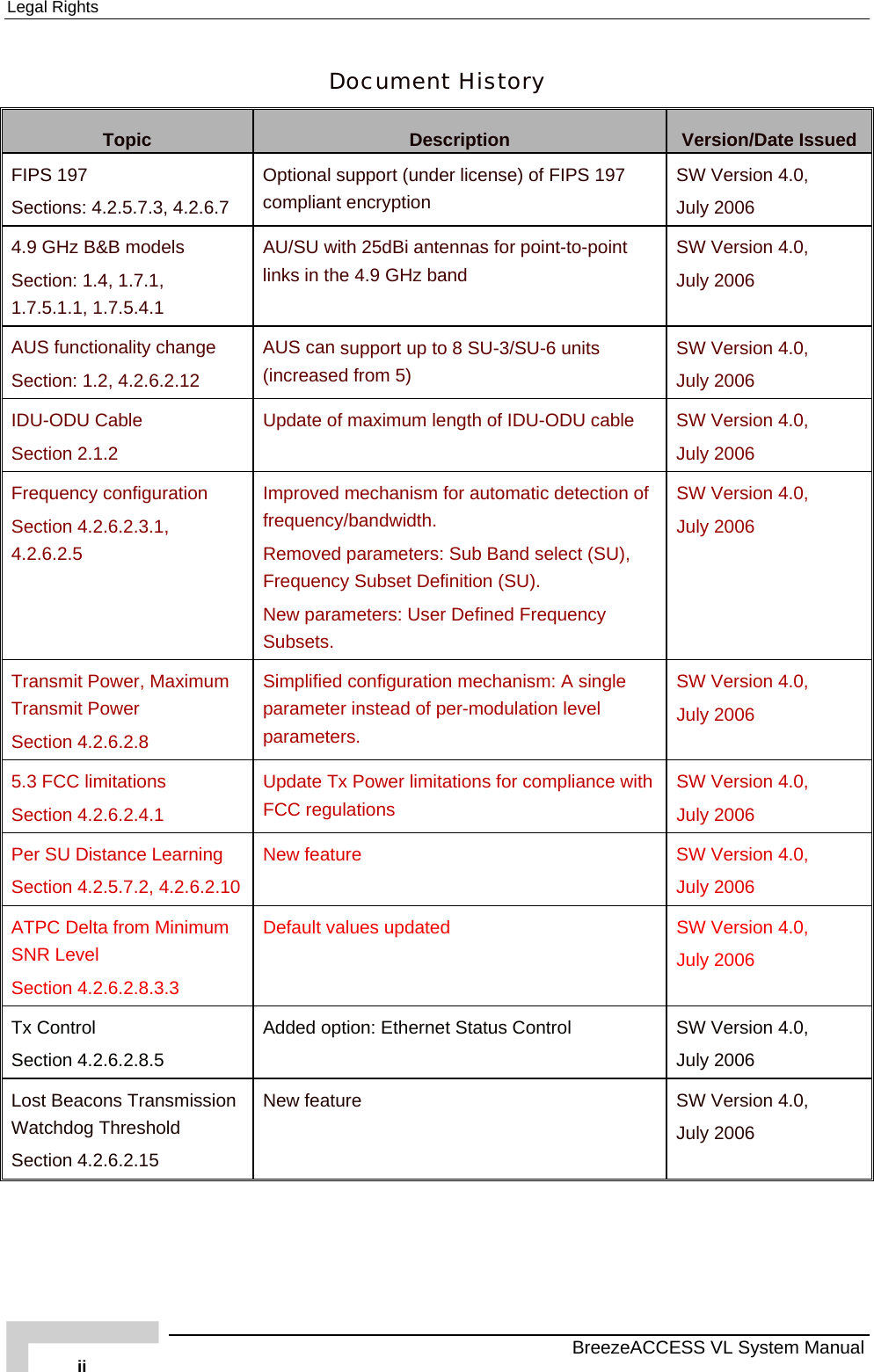
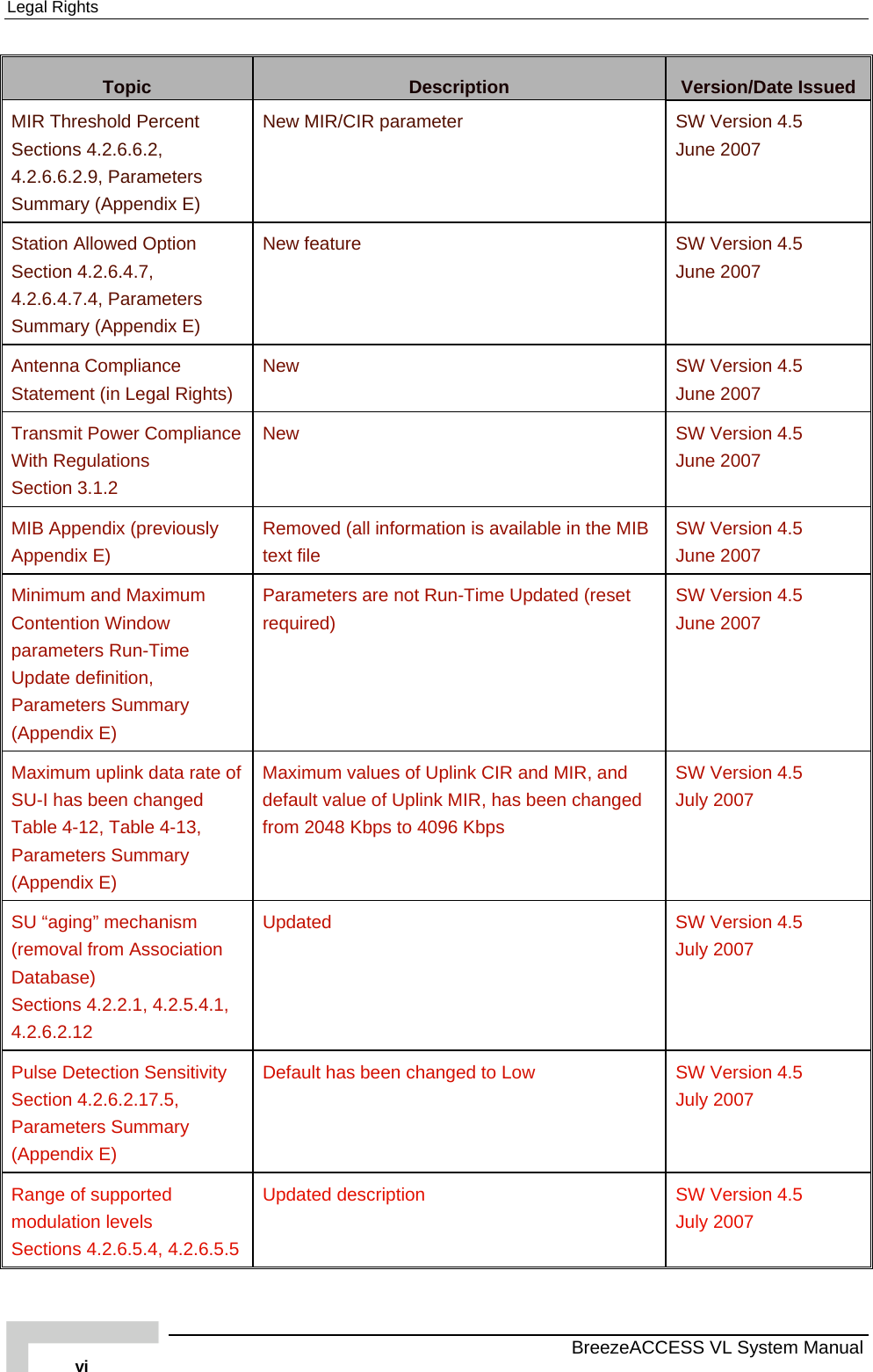
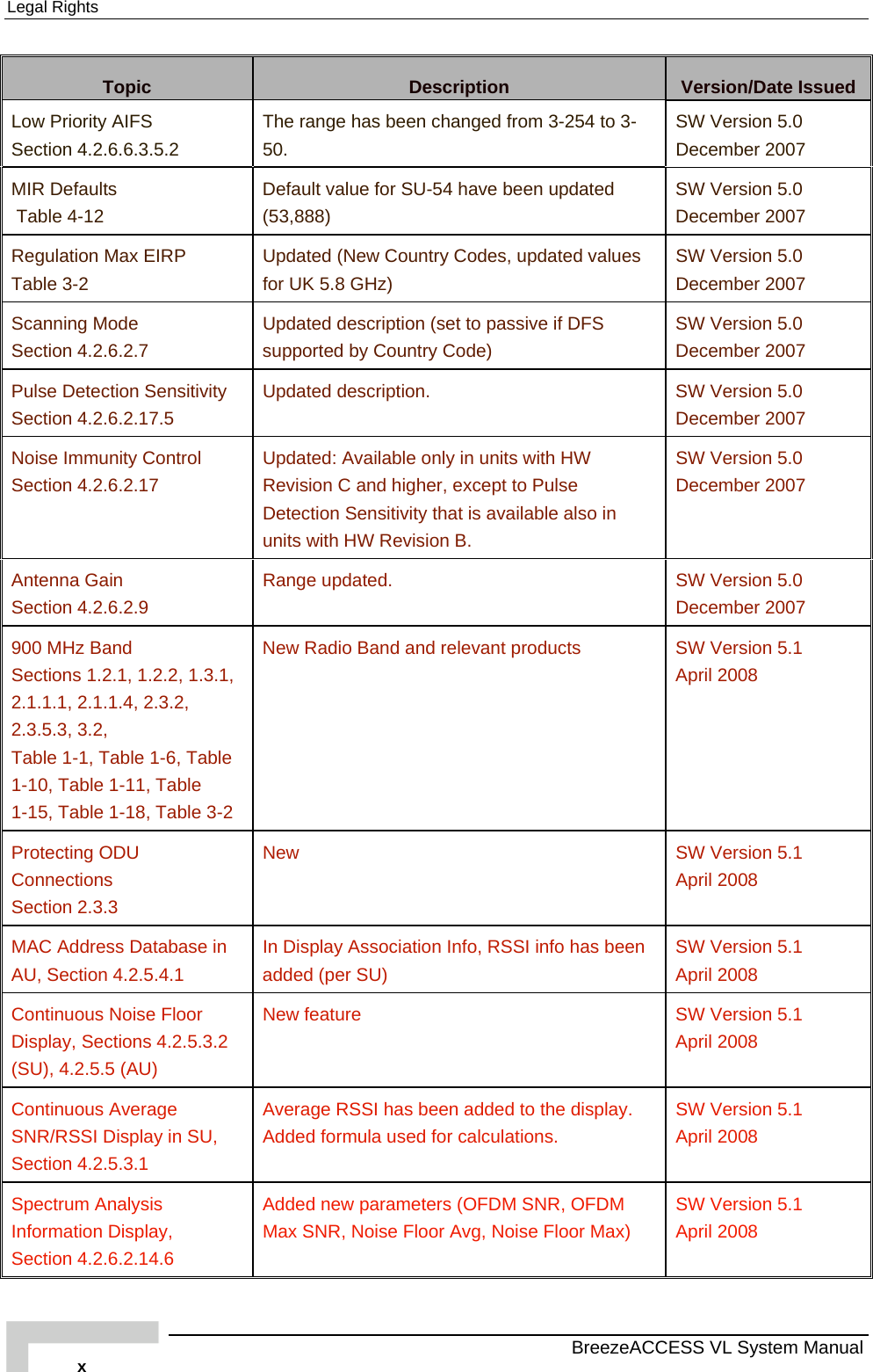

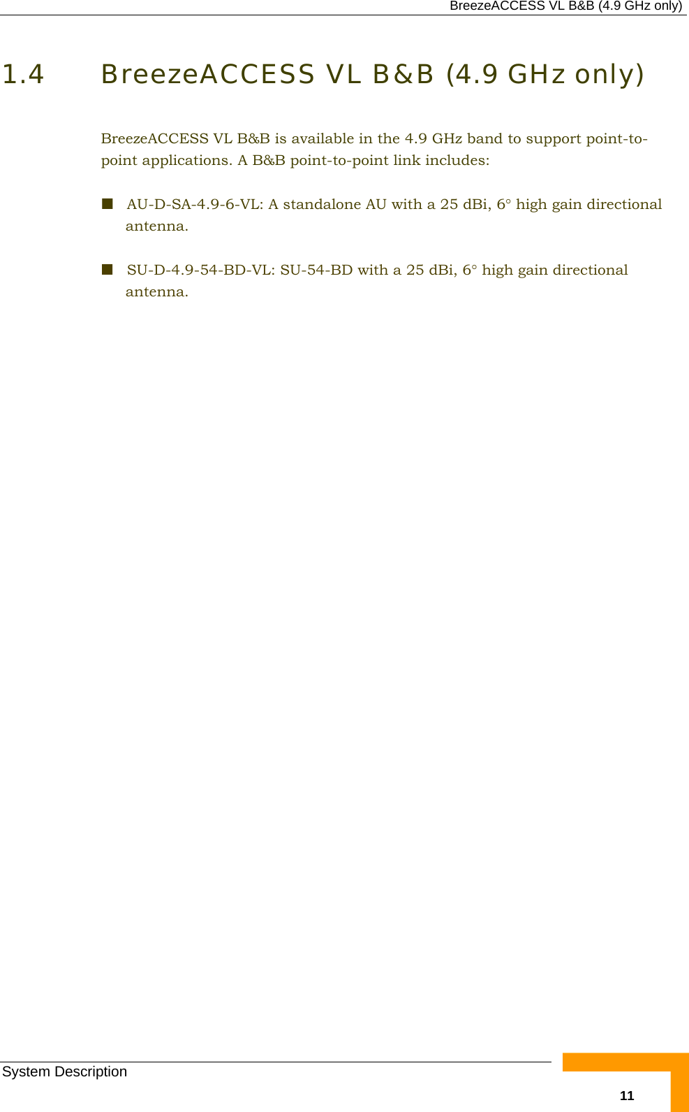
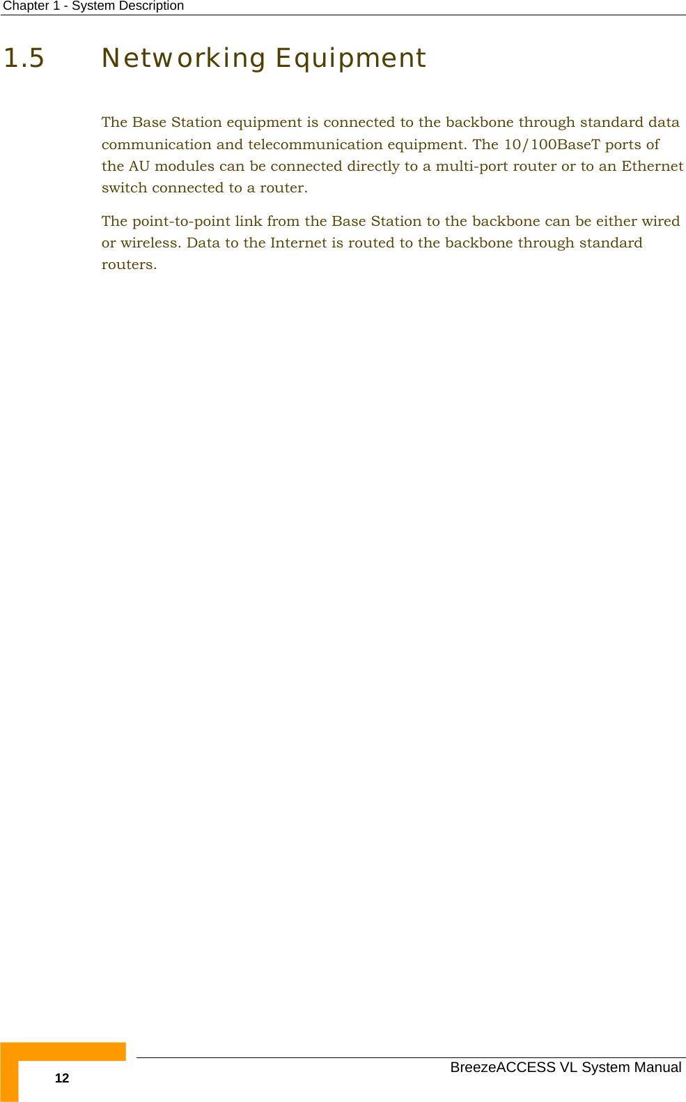
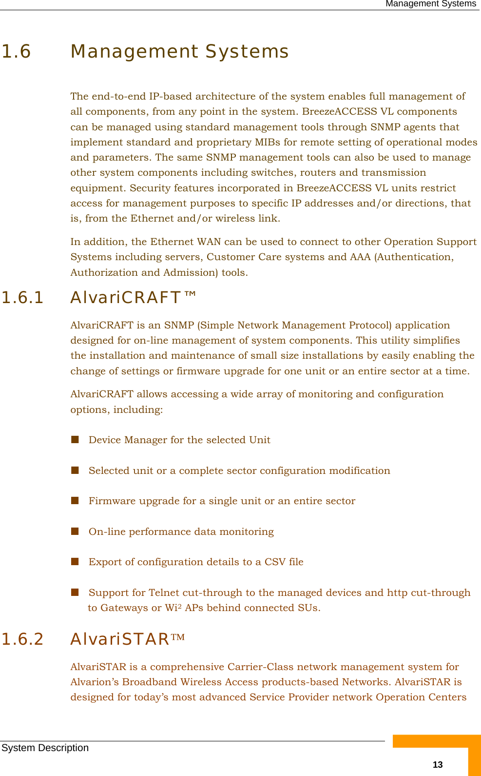
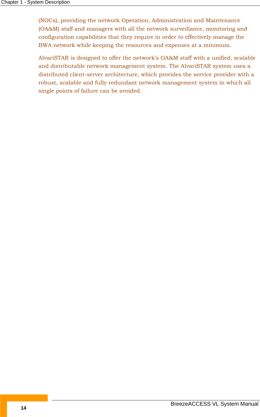
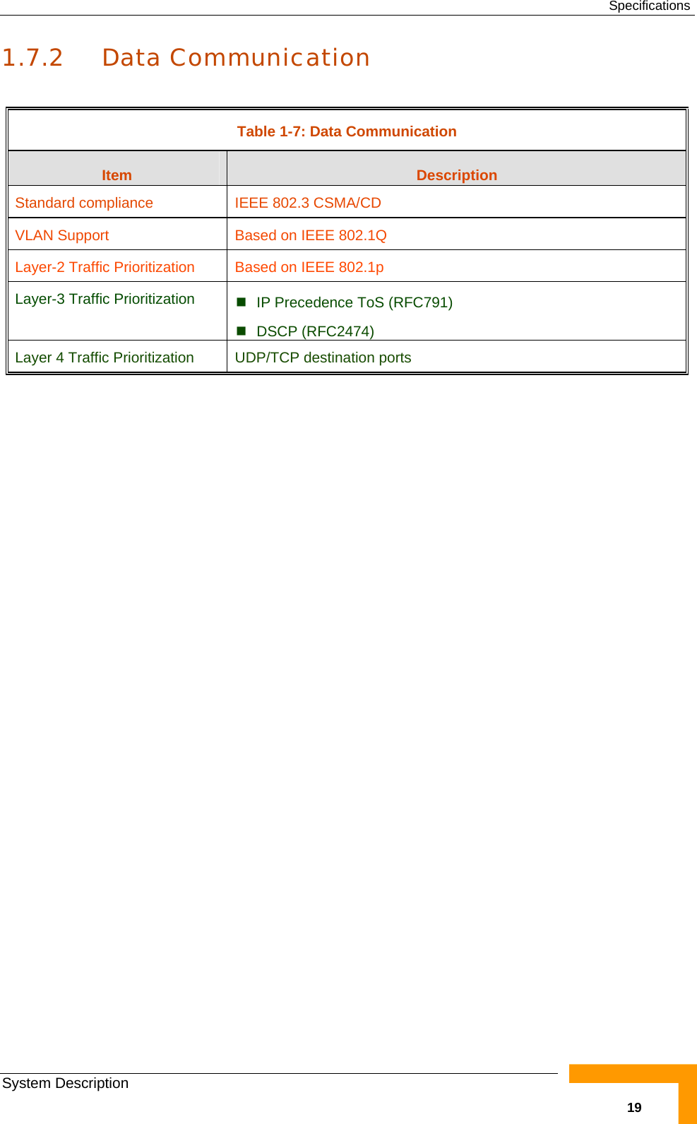
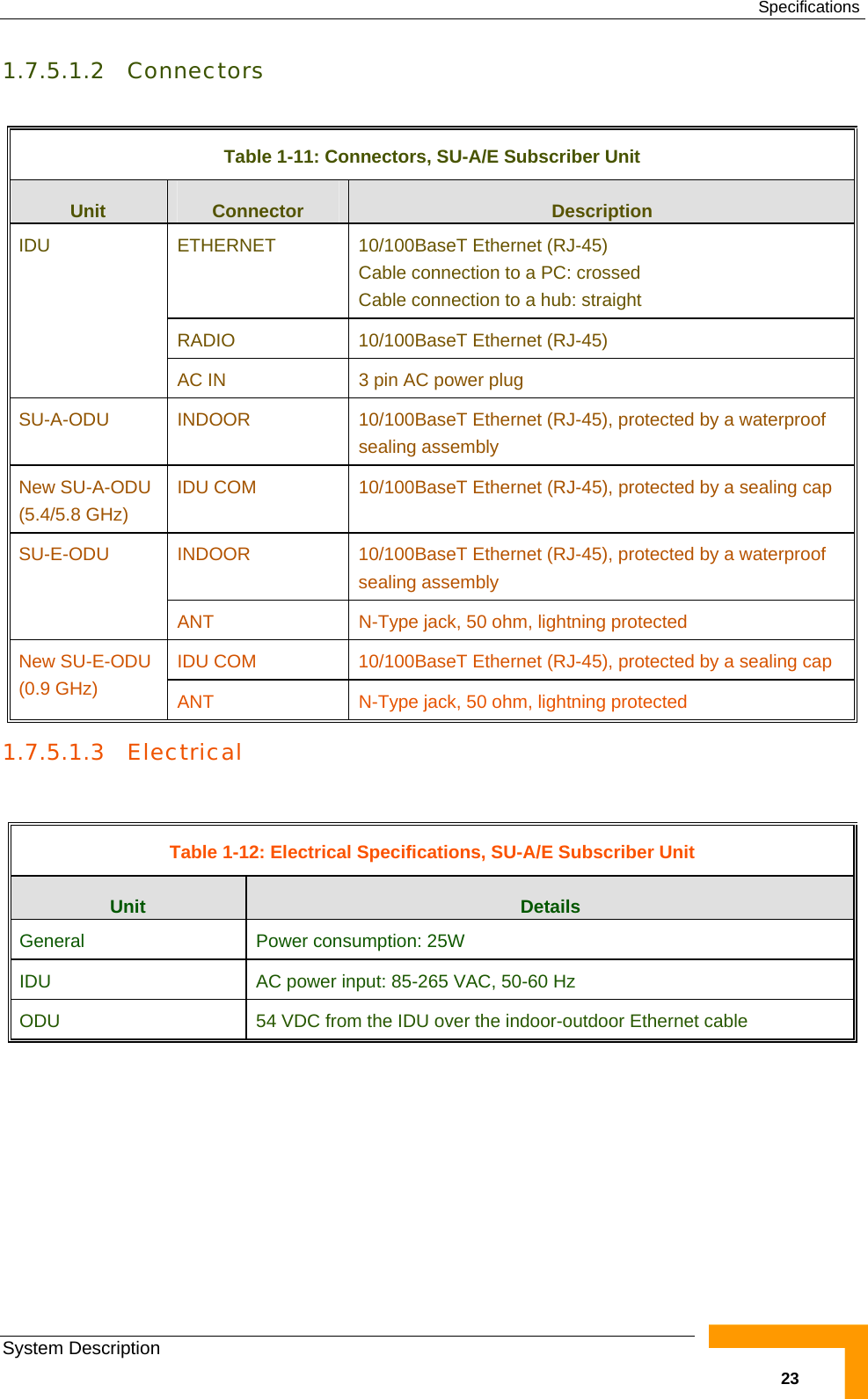
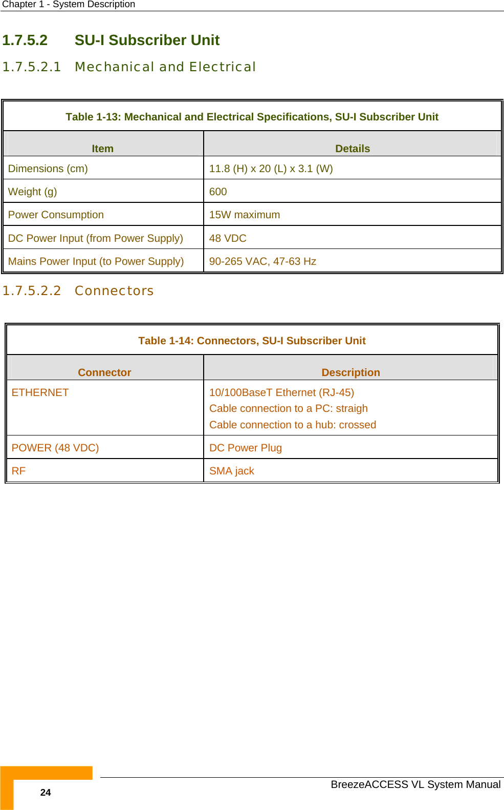
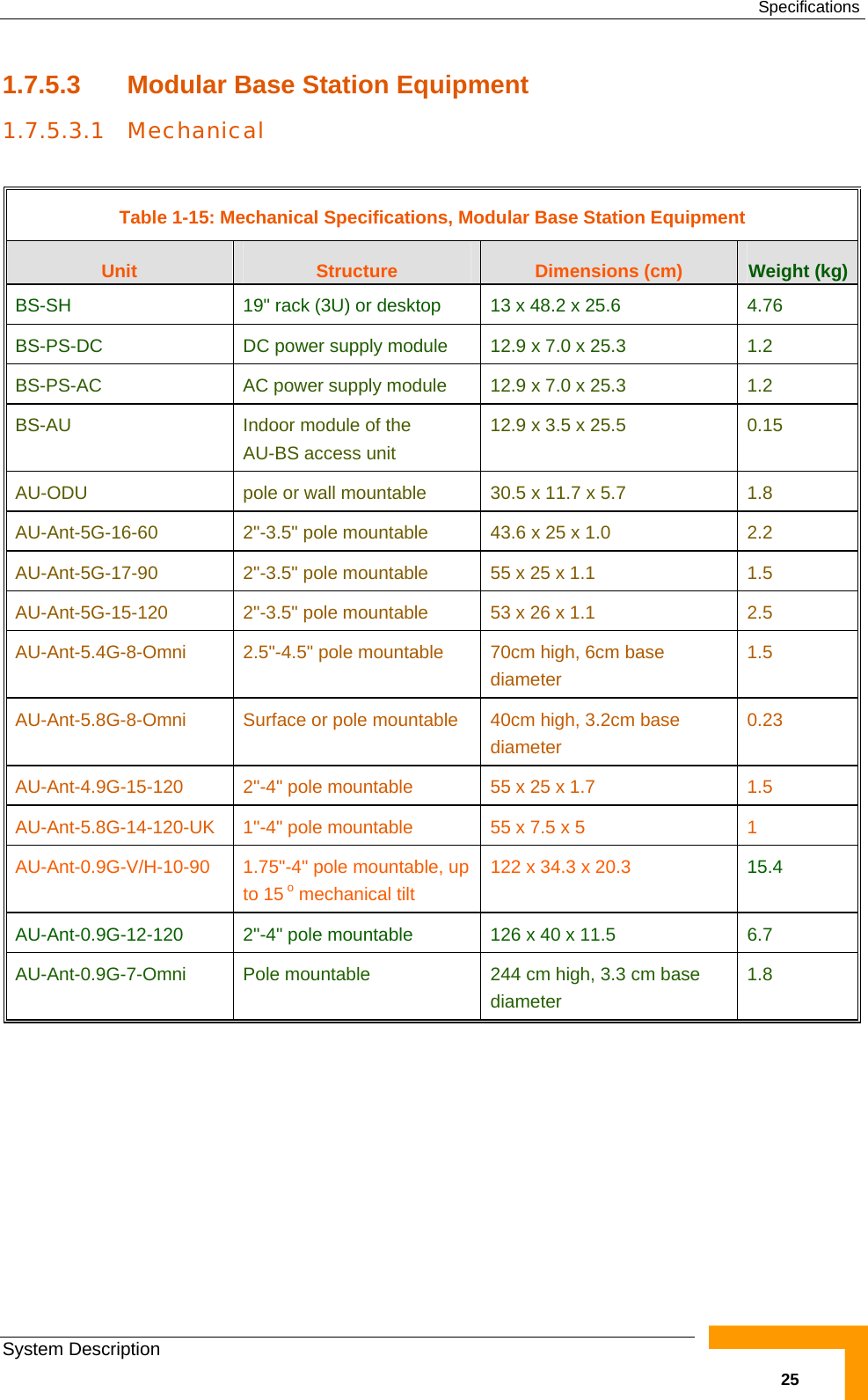
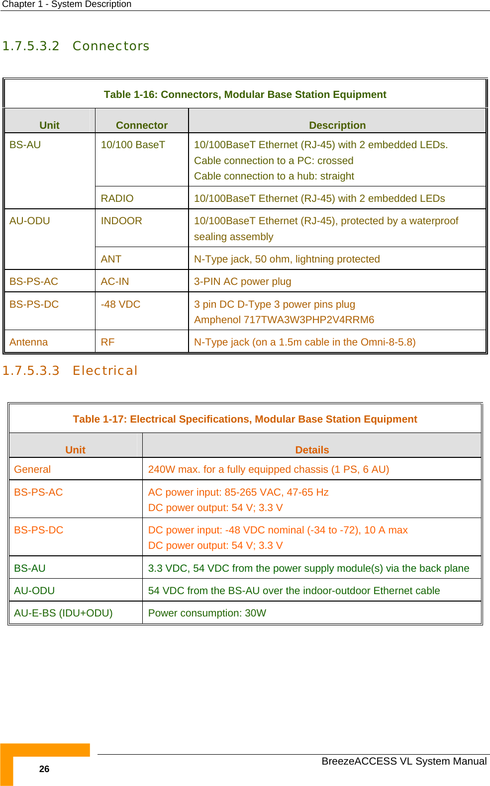
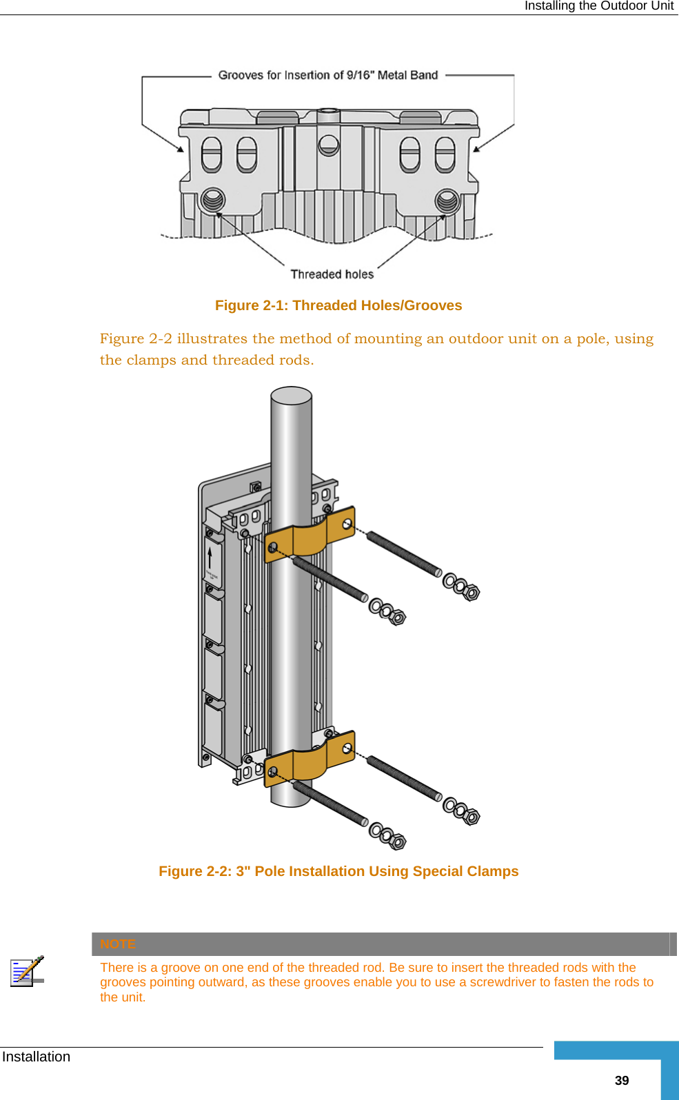
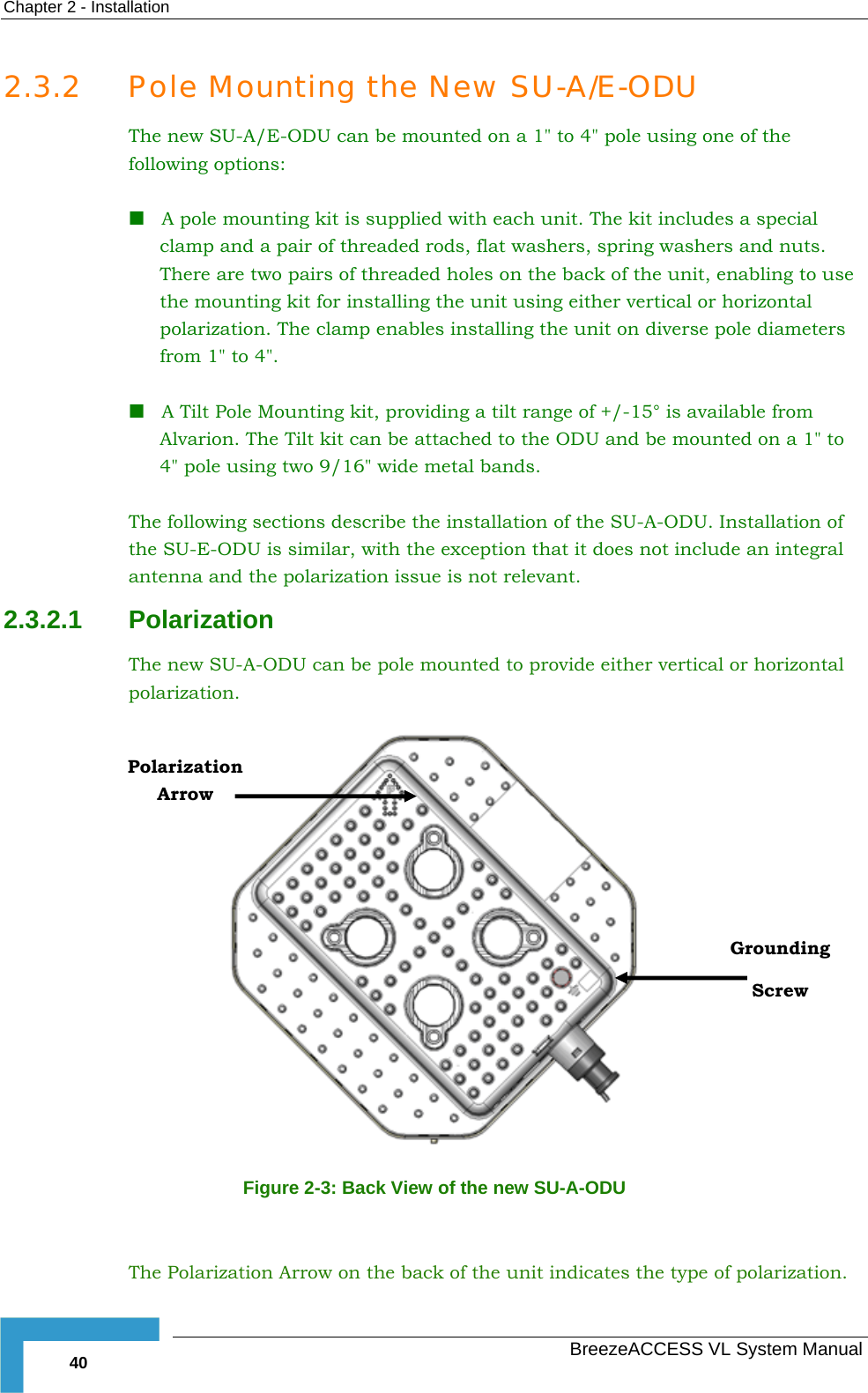
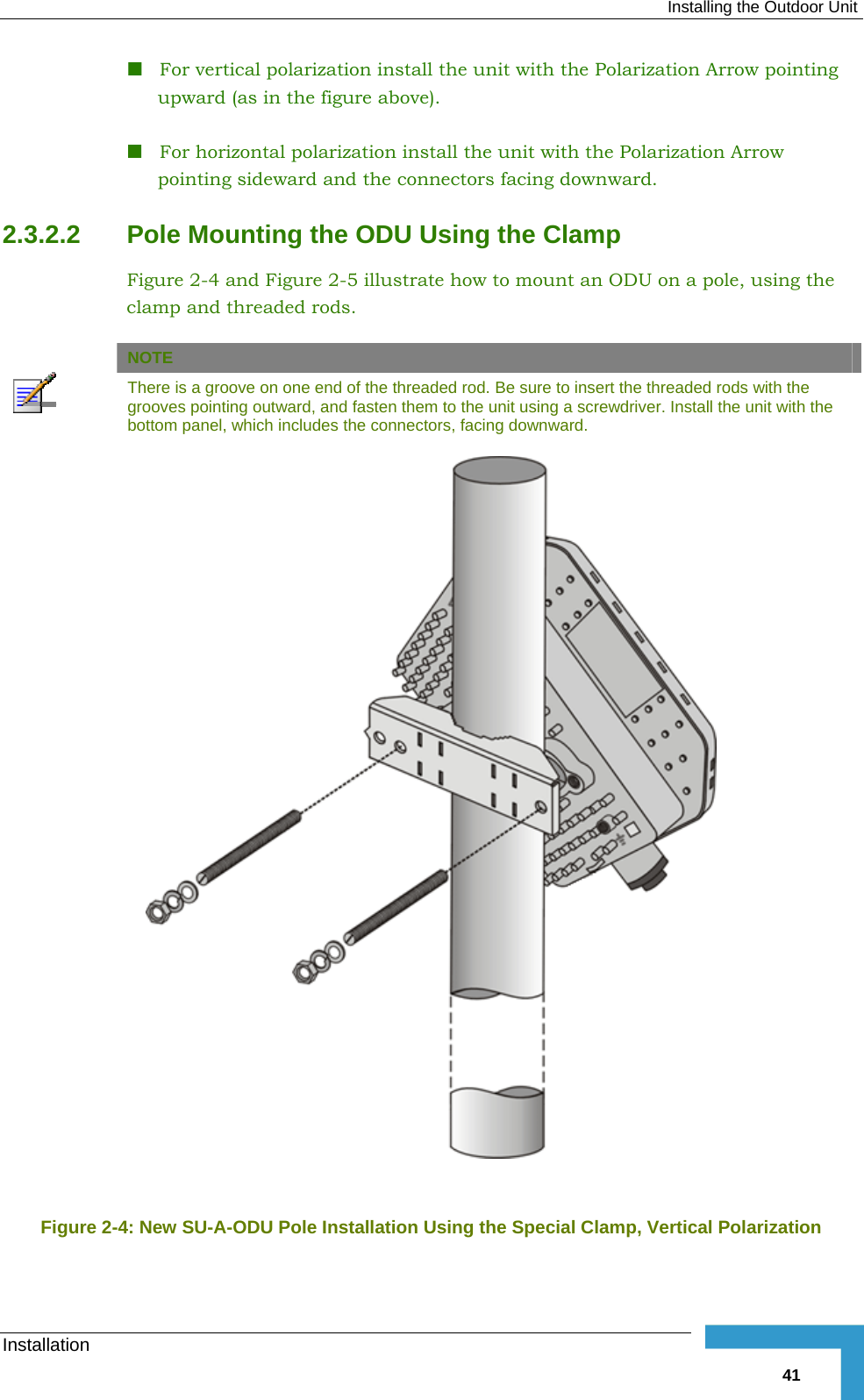
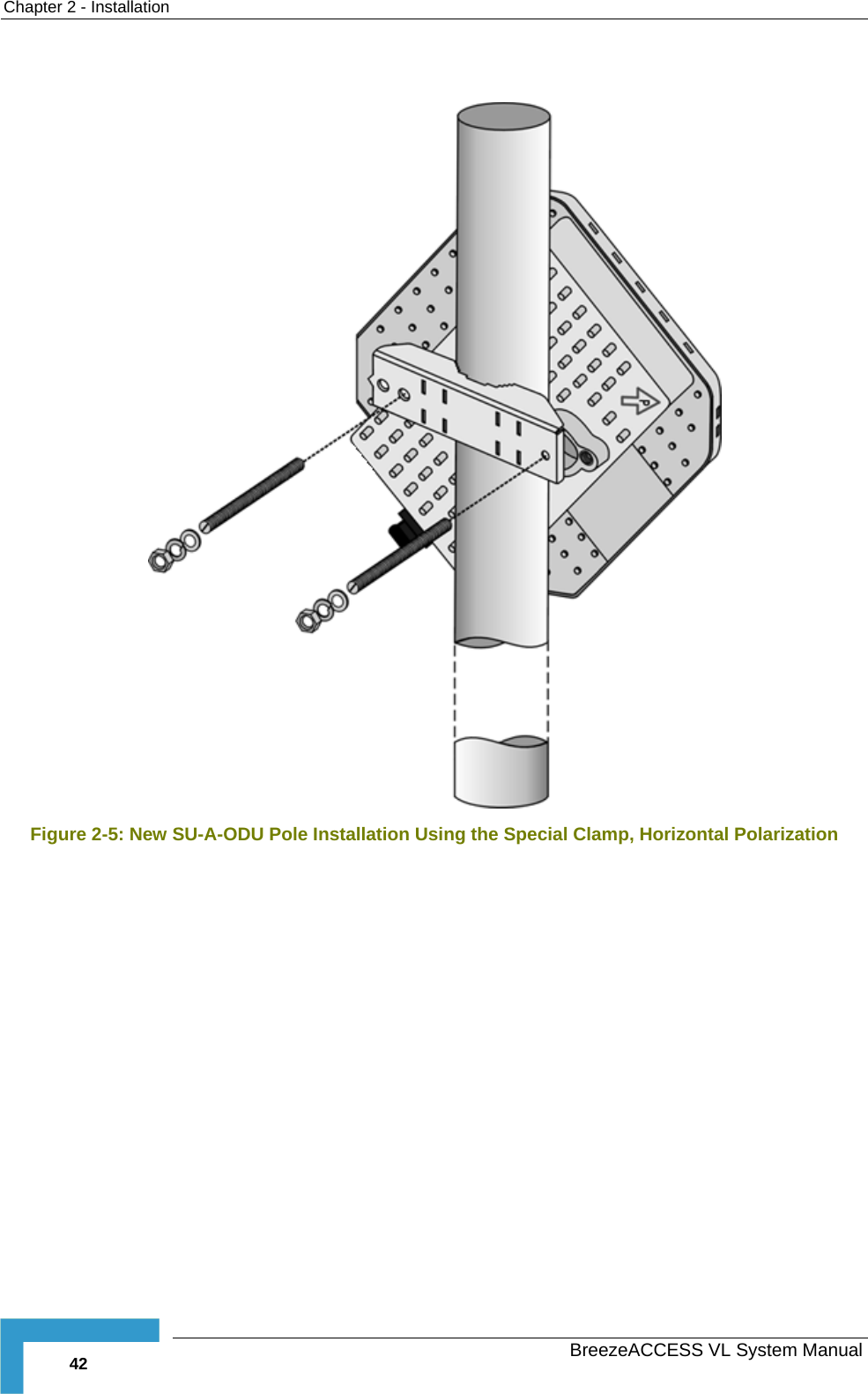
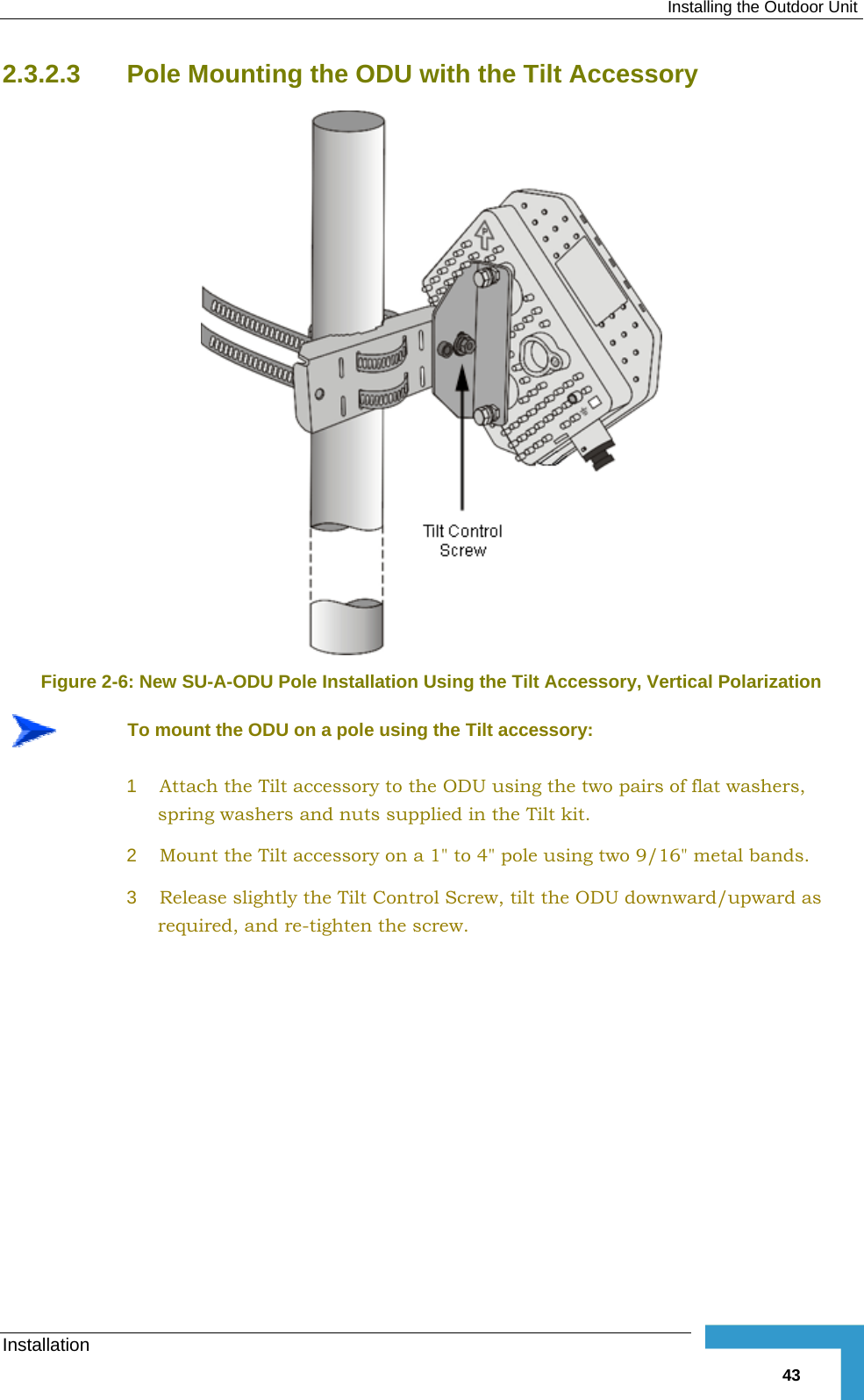
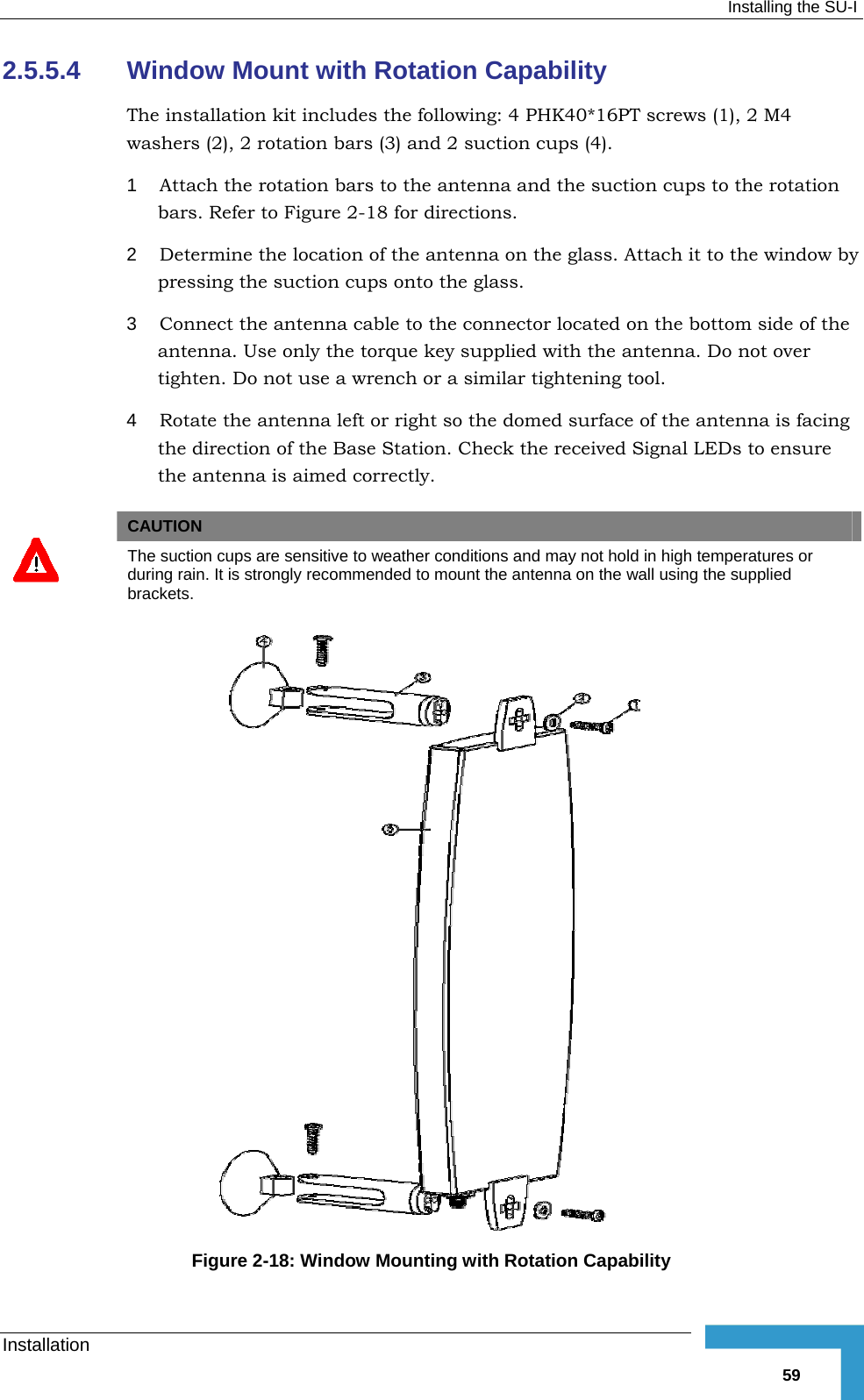
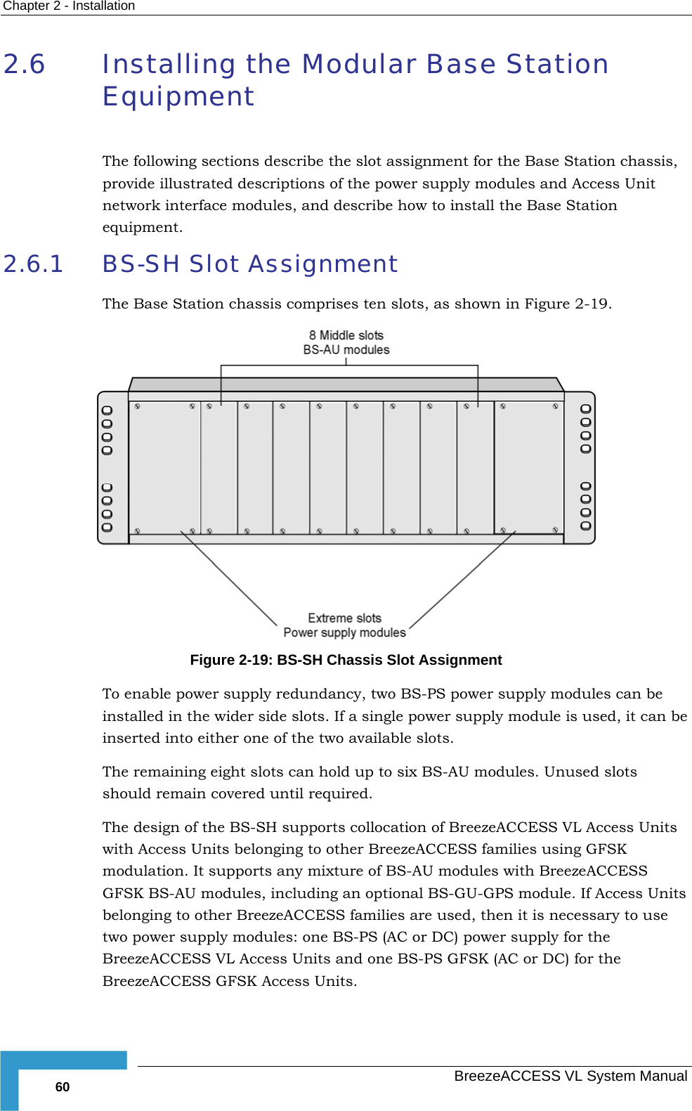
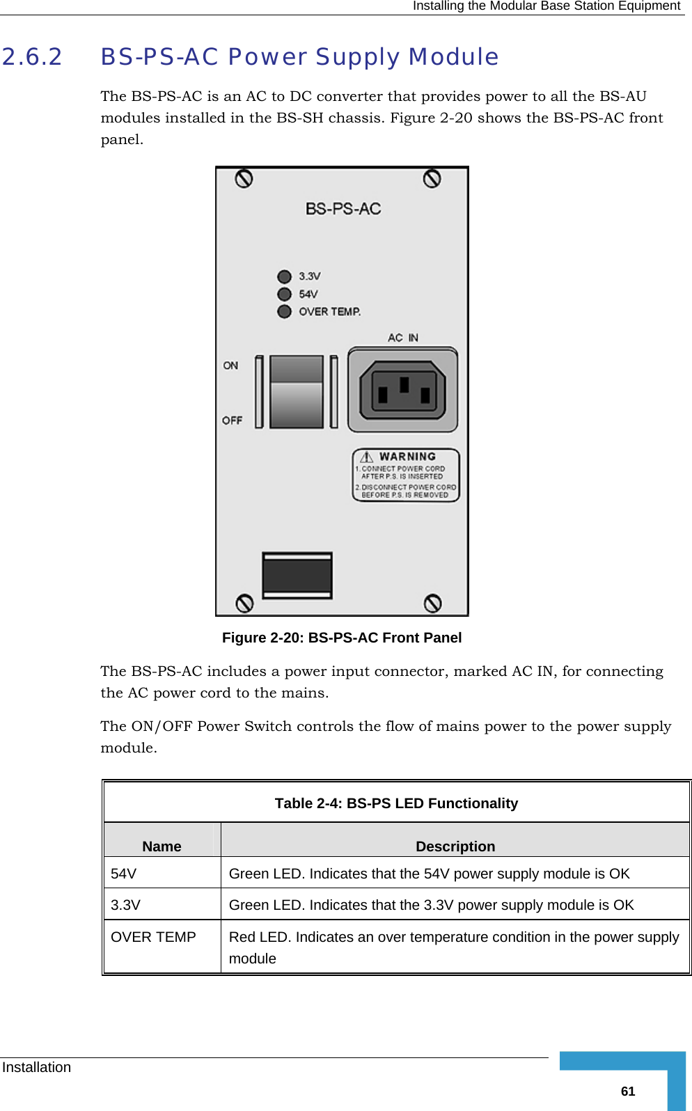
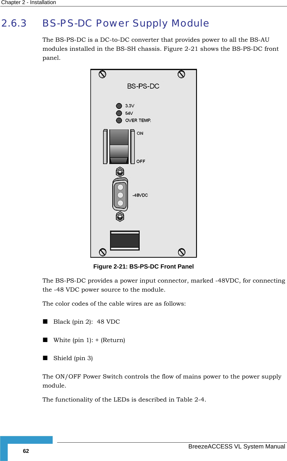
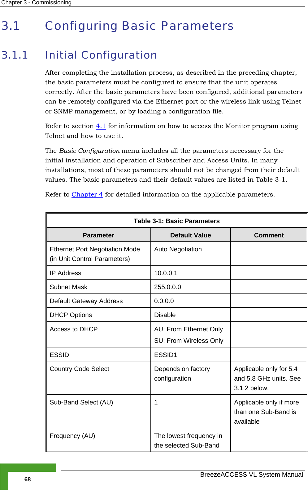

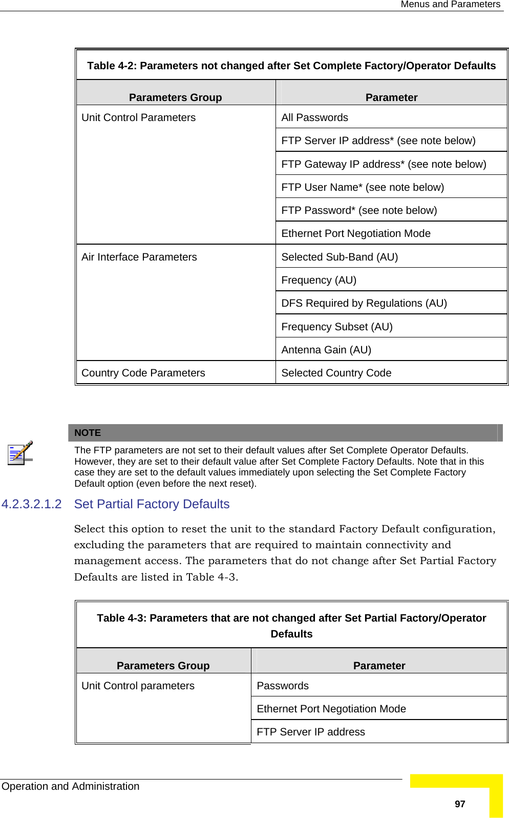
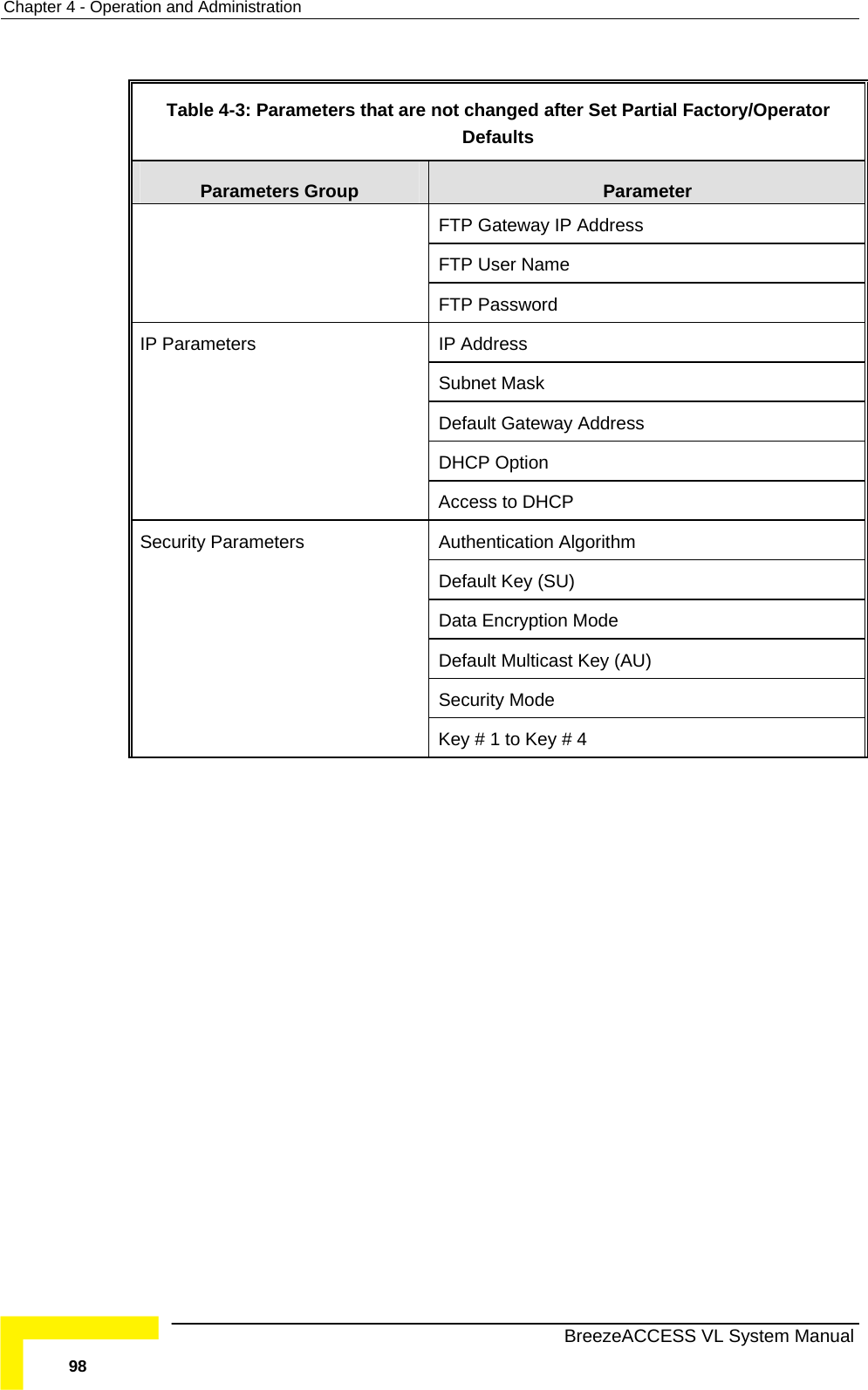
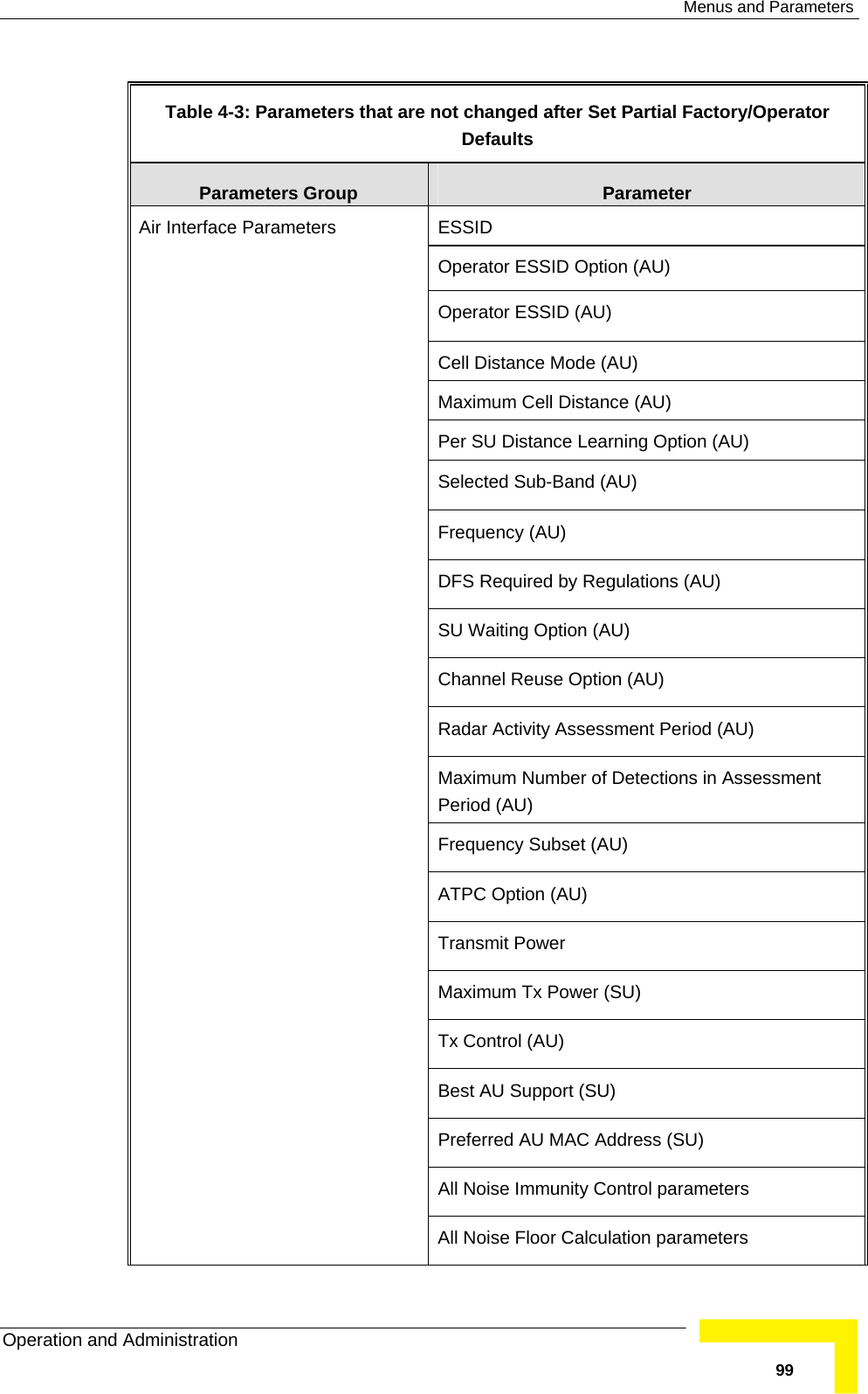
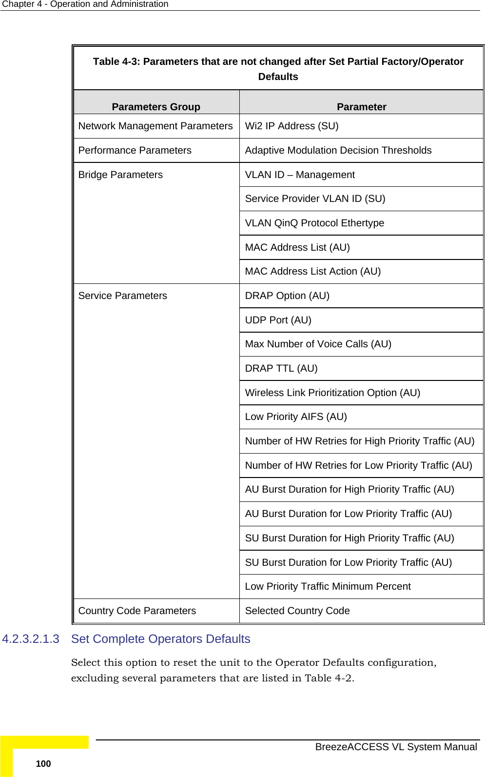
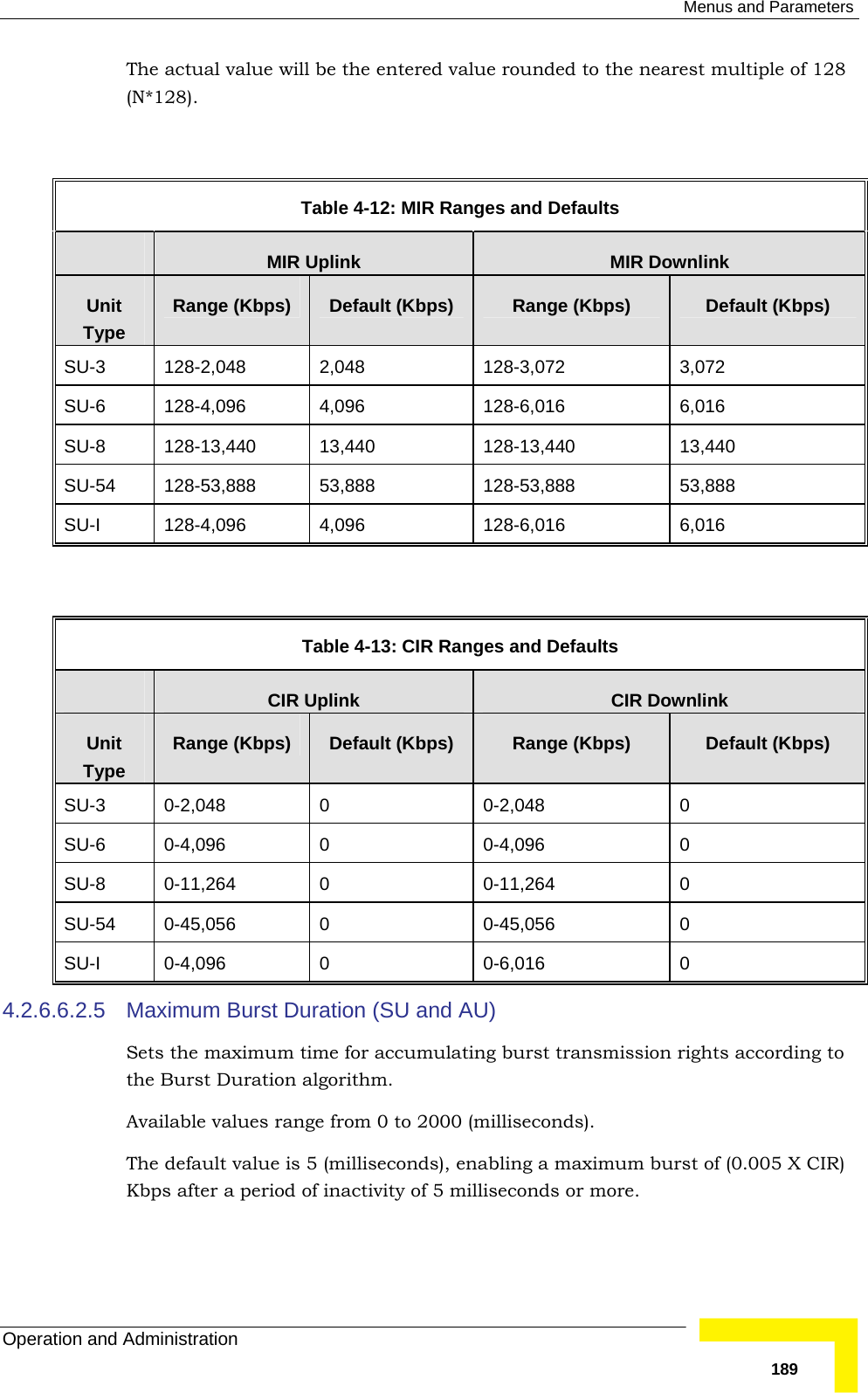

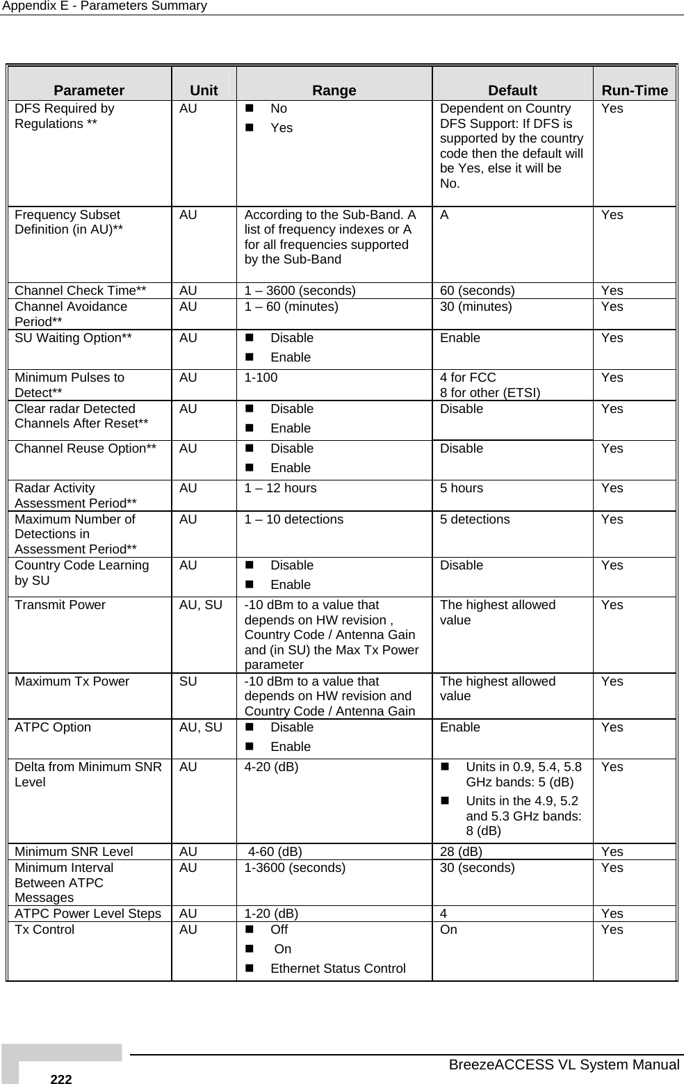
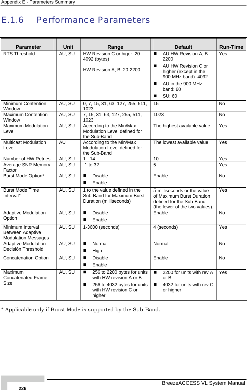
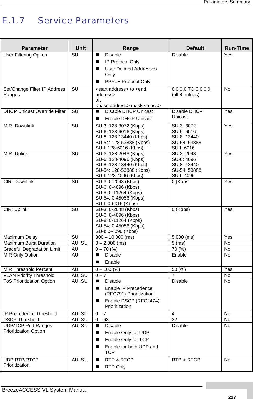
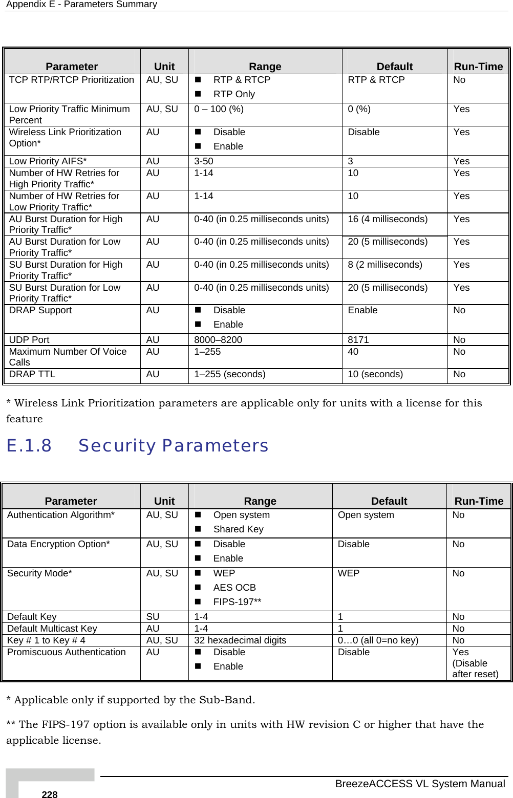
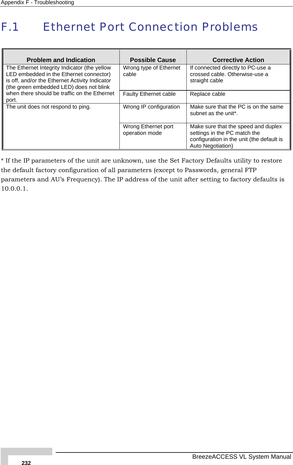
![Appendix A - Software Version Loading Using TFTP BreezeACCESS VL System Manual 206 Firmware upgrades to the unit's FLASH memory can be performed by a simple loading procedure using a TFTP application. Before performing an upgrade procedure, be sure you have the correct files and most recent instructions. Upgrade packages can be obtained from the Technical Support section of Alvarion's web site, http://www.alvarion.com/. CAUTION Shutting down power to the unit before completion of the loading procedure may cause the unit to be inoperable. To load software versions: 1 Verify that IP connectivity to the required unit is established. 2 Ensure that the IP address of the PC from which the upgrade is to be performed belongs to the same subnet as the unit to be upgraded, unless the unit is behind a router. If the unit is behind a router, verify that the unit is configured with the correct Default Gateway Address. 3 To view the current IP parameters of the unit, use the Monitor program by connecting the PC to the unit either directly or via Telnet. To access the IP parameters via the Monitor program: a From the Main Menu select 1 - Info Screens. b From the Info Screen menu select 2 - Show Basic Configuration. The current basic configuration is displayed, including the run time values for the IP Address, Subnet Mask and Default Gateway Address parameters. 4 To modify any of the IP parameters: a From the Main Menu, select 3 - Basic Configuration. b To configure the IP address, select: 1 - IP Address. c To configure the subnet mask, select 2 - Subnet Mask. d To configure the default gateway address, select 3 - Default Gateway Address. e Reset the unit to apply the new IP parameters. 5 To verify the connection, PING the unit's IP address and verify that PING replies are being received. 6 Use the TFTP utility, with the following syntax, to perform the upgrade: tftp -i hostaddress put sourcefile [destinationfile] where -i is for binary mode and hostaddress is the IP address of the unit to be upgraded. put causes the PC client to send a file to the hostaddress.](https://usermanual.wiki/Alvarion-Technologies/VL-900/User-Guide-957838-Page-234.png)