Alvarion Technologies VL-IF 5.8GHz Wireless LAN User Manual 307453
Alvarion Ltd. 5.8GHz Wireless LAN 307453
UserManual.wiki
>
Alvarion Technologies
>
VL-IF User Manual
>
User Manual
Contents
1.
User Manual
2.
revised user manual
3.
Regulatory
User Manual
Navigation menu
Upload a User Manual
Namespaces
Wiki Guide
HTML
PDF
Info
Views
User Manual
Discussion / Help
Navigation
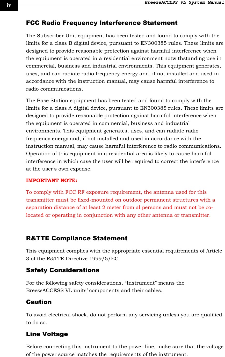
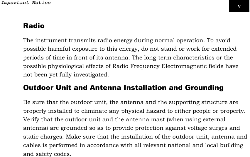
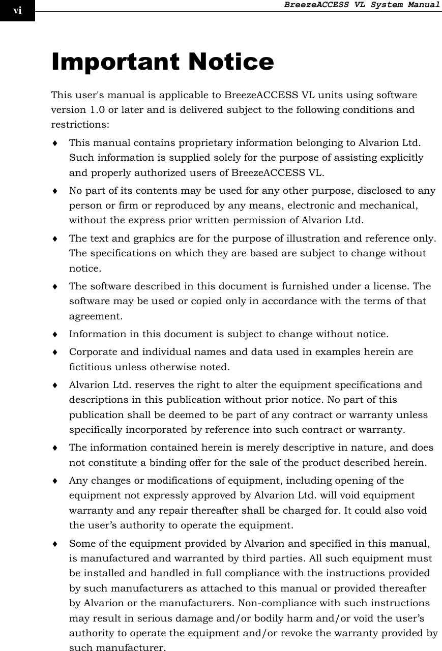
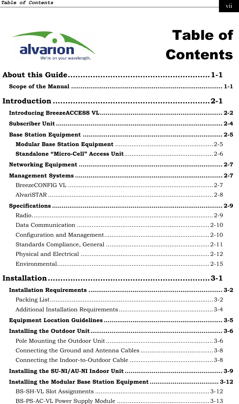
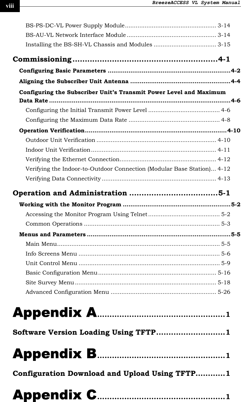


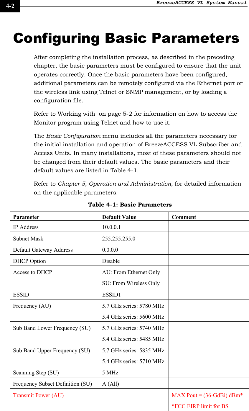

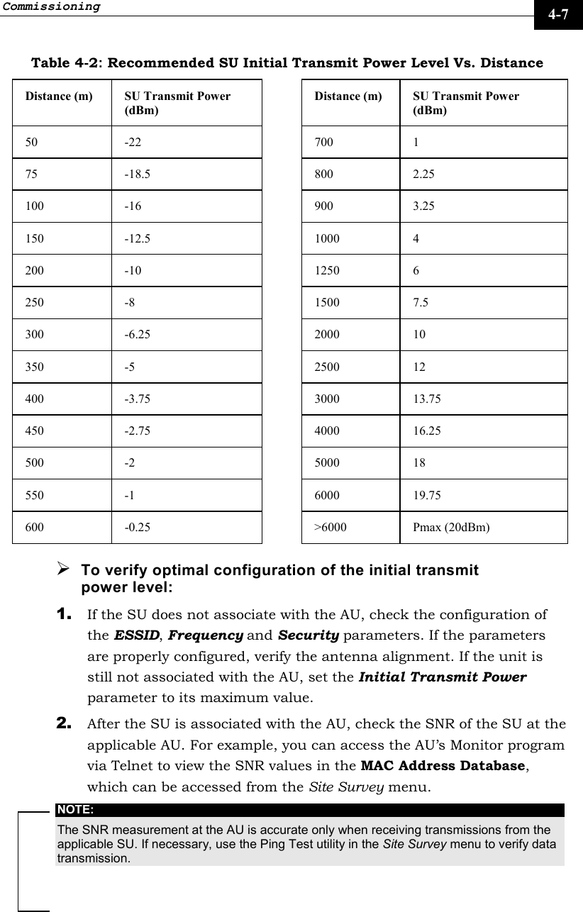
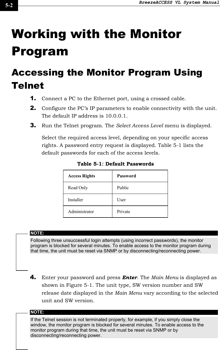
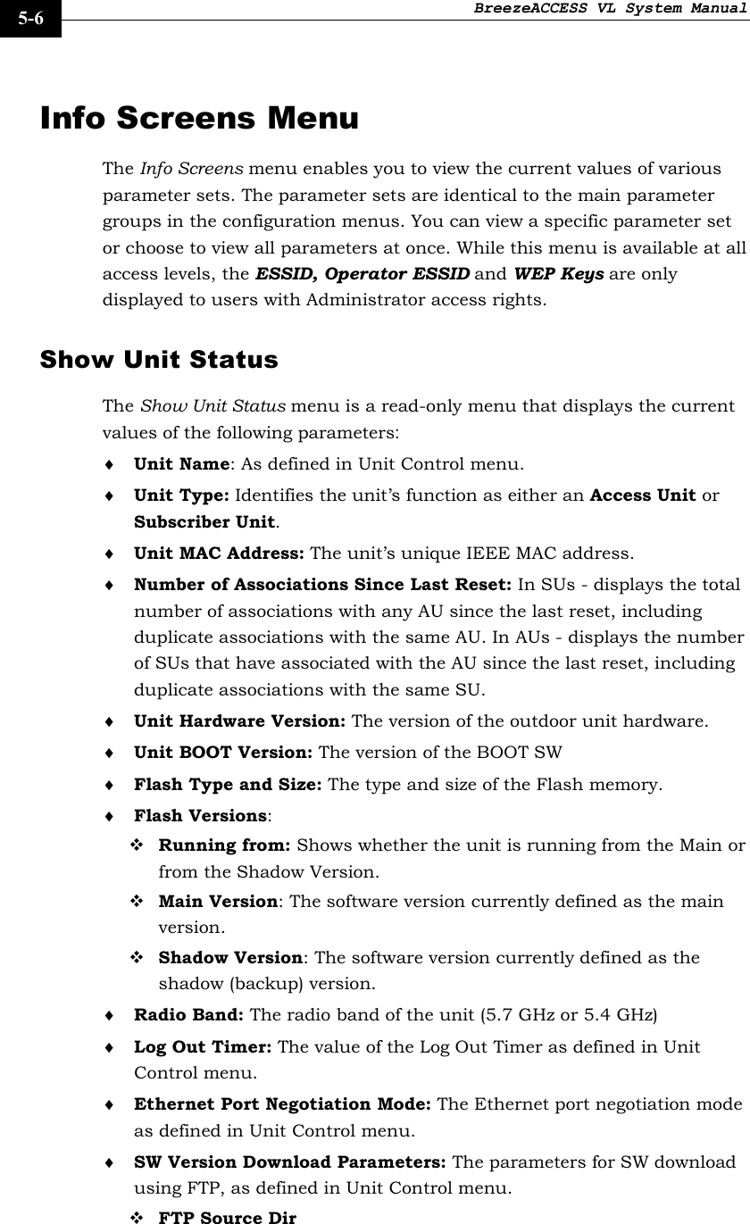
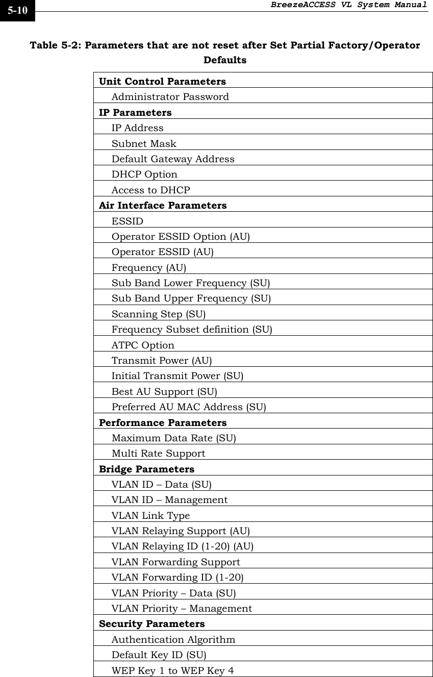
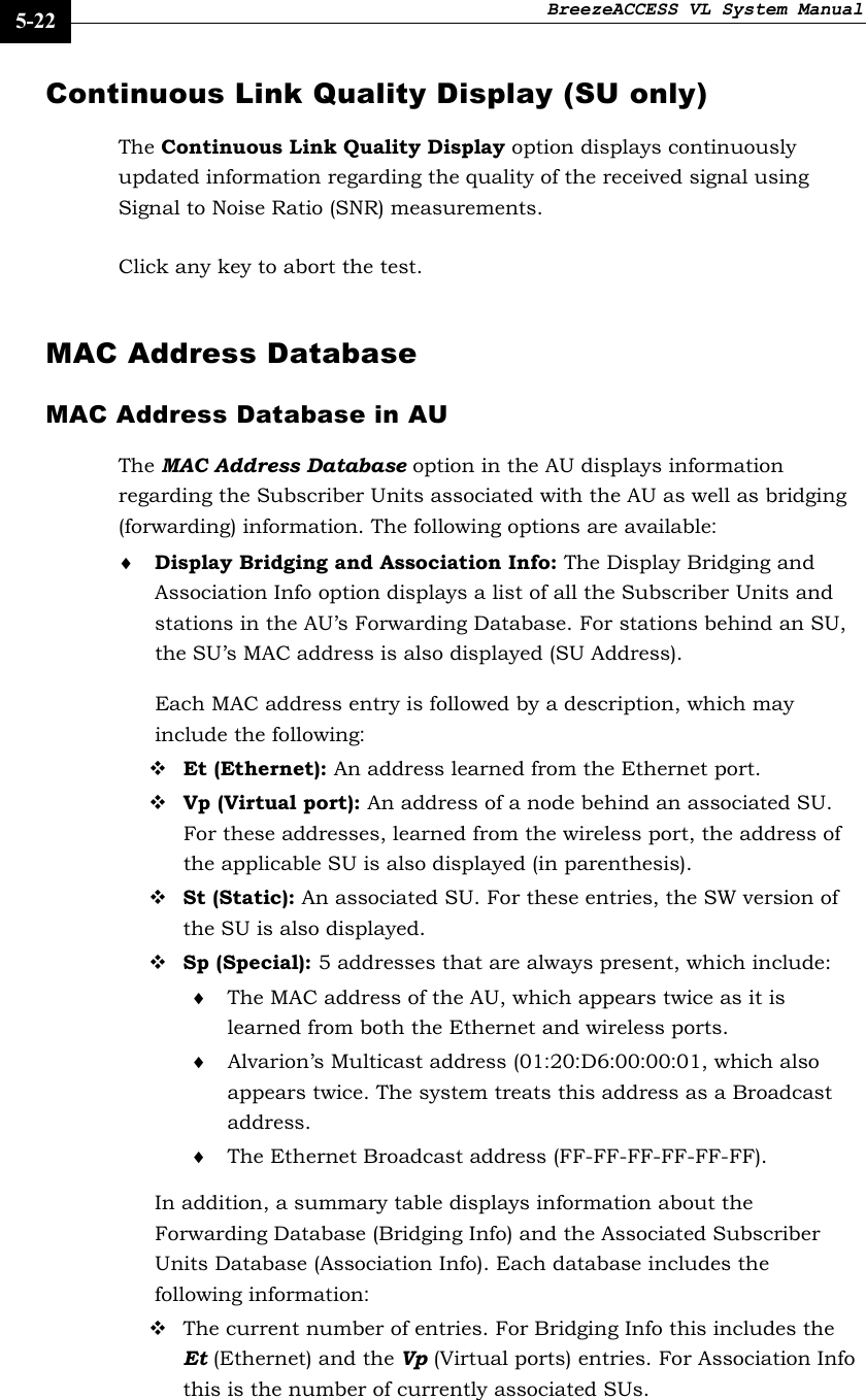

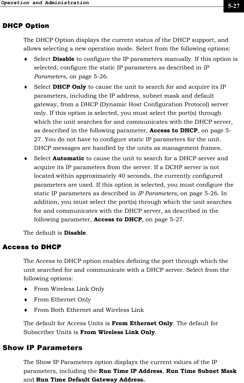
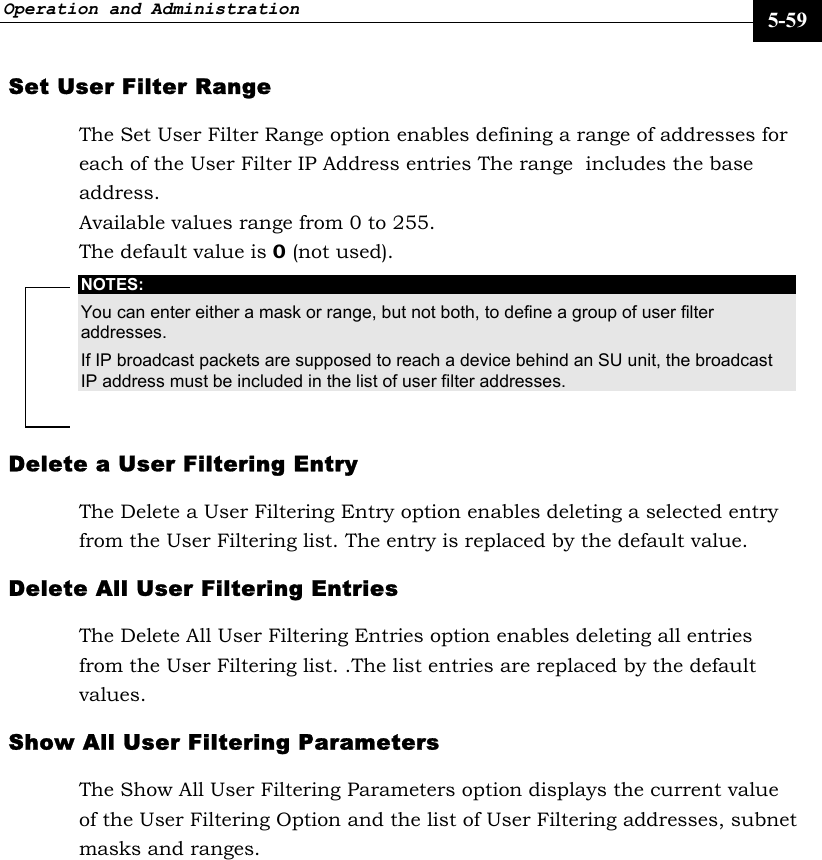
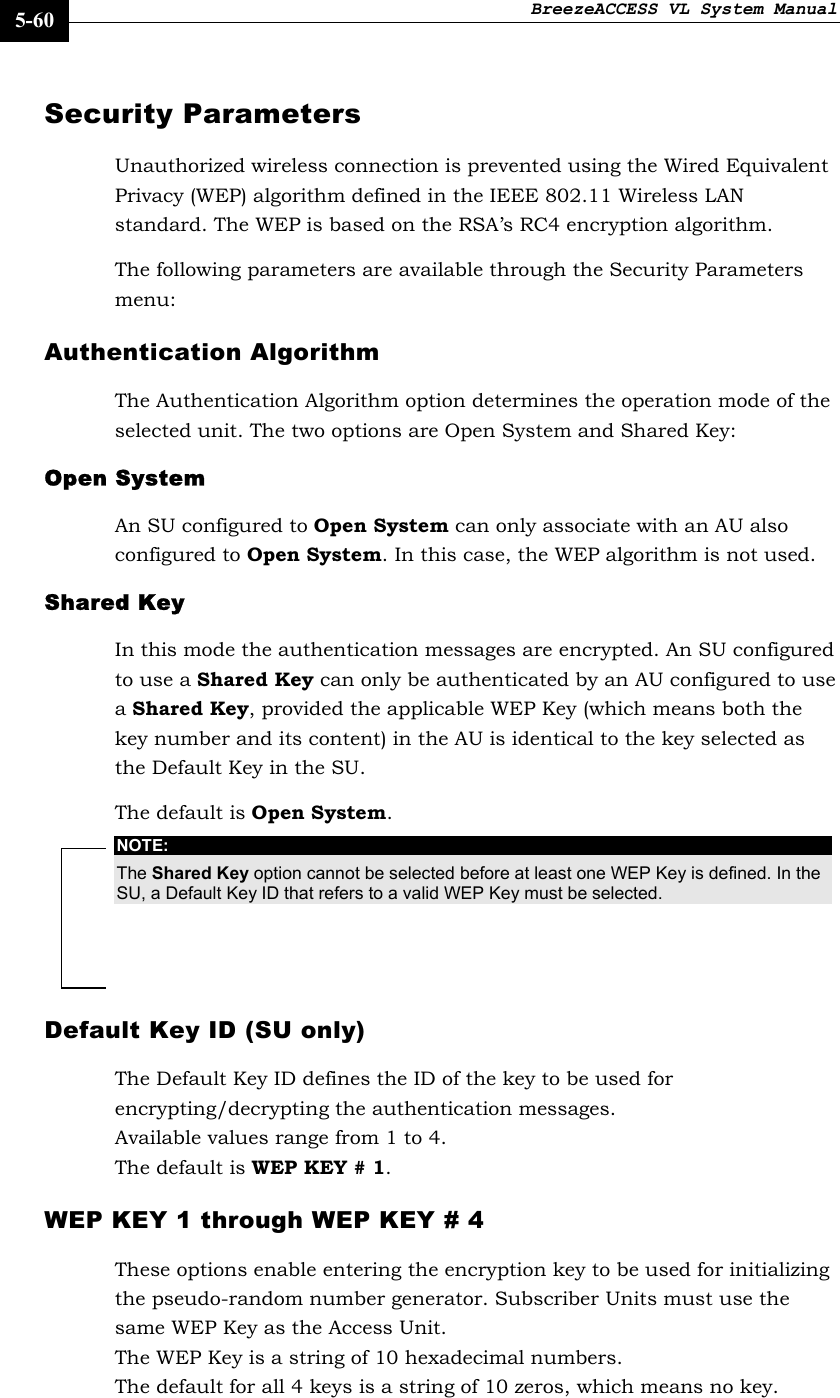
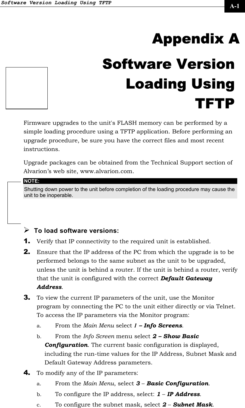
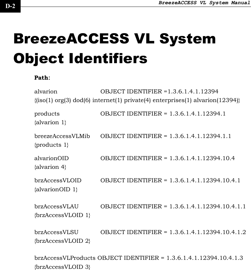
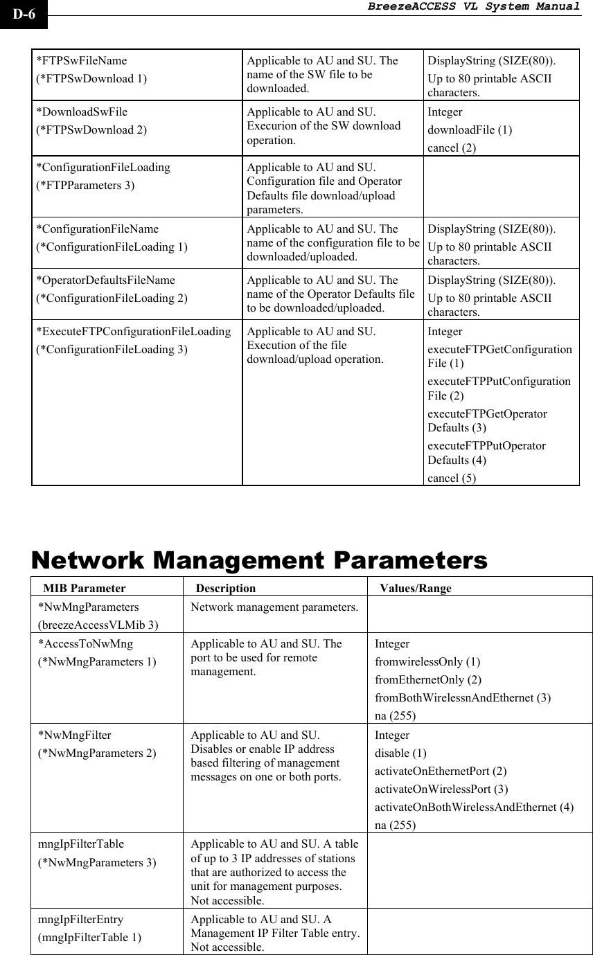
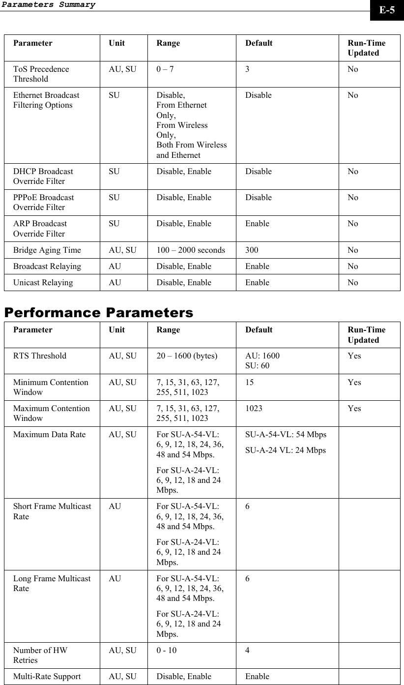
![BreezeACCESS VL System Manual A-2 d. To configure the default gateway address, select 3 - Default Gateway Address. 5. To verify the connection, PING the unit’s IP address and verify that PING replies are being received. 6. Use the TFTP utility, with the following syntax, to perform the upgrade: tftp –i hostaddress put sourcefile [destinationfile] where -i is for binary mode and hostaddress is the IP address of the unit to be upgraded. put causes the PC client to send a file to the hostaddress. destinationfile is the name of the file to be loaded. 7. Use the SNMP write community <SnmpWriteCommunity>.dwn to define the destination filename. The default write community is private. For example, to load the upgrade file au1_0_6.bz to an AU whose IP address is 206.25.63.65: tftp –i 206.25.63.65 put au1_0_6.bz private.dwn 8. When the loading is complete, the following message is displayed: Download operation has been completed successfully 9. The FLASH memory can store two software versions. One version is called Current and the second version is called Shadow. The new version is loaded into the Shadow (backup) FLASH memory. To check that the new firmware was properly downloaded, view the firmware versions stored in the FLASH, as follows: a. From the Main Menu, select 2 – Unit Control. b. From the Unit Control menu, select 5 – Flash Memory Control. c. From the Flash Memory Control menu, select S – Show Flash Versions. The following information is displayed: Flash Versions =========== Running from :main version Main Version :au1_0_5.bz Shadow Version :au1_0_6.bz](https://usermanual.wiki/Alvarion-Technologies/VL-IF.User-Manual/User-Guide-307453-Page-122.png)