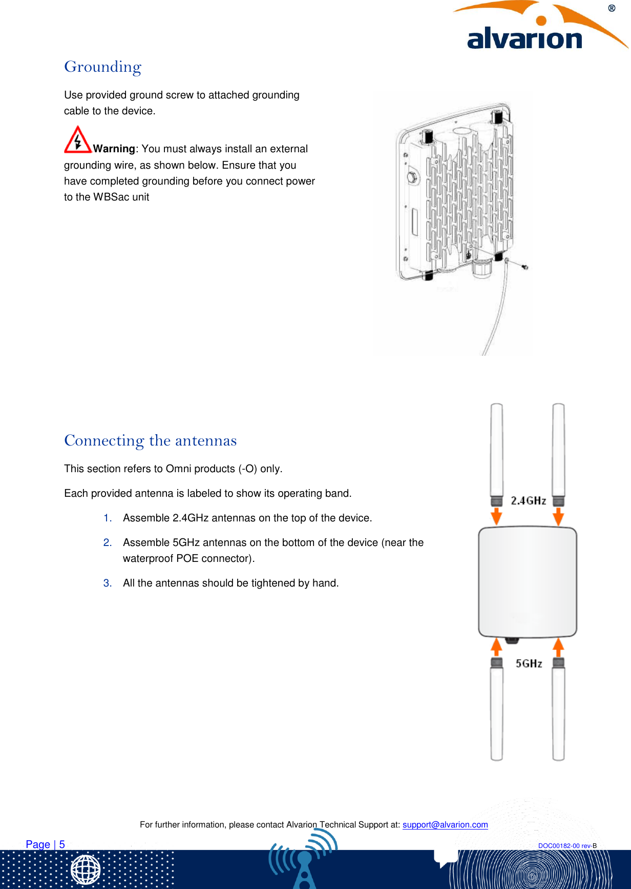
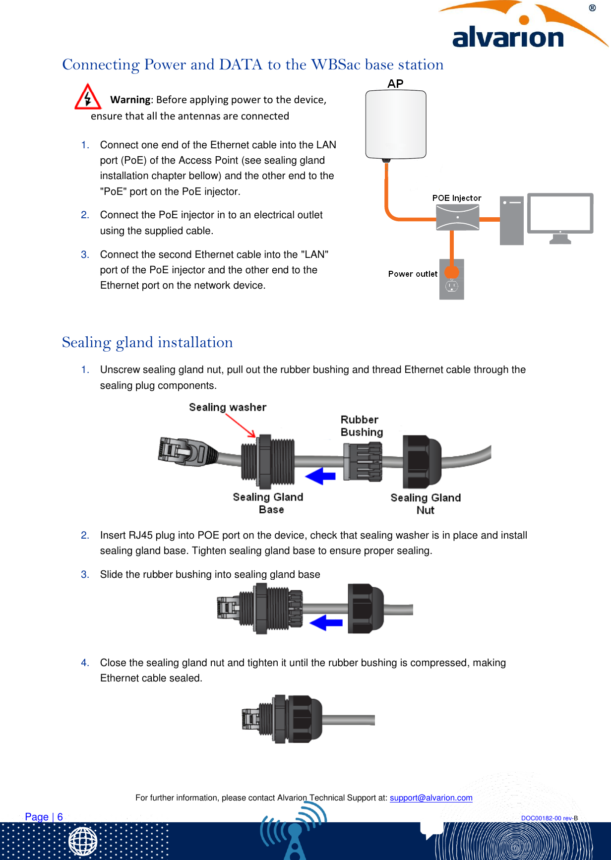
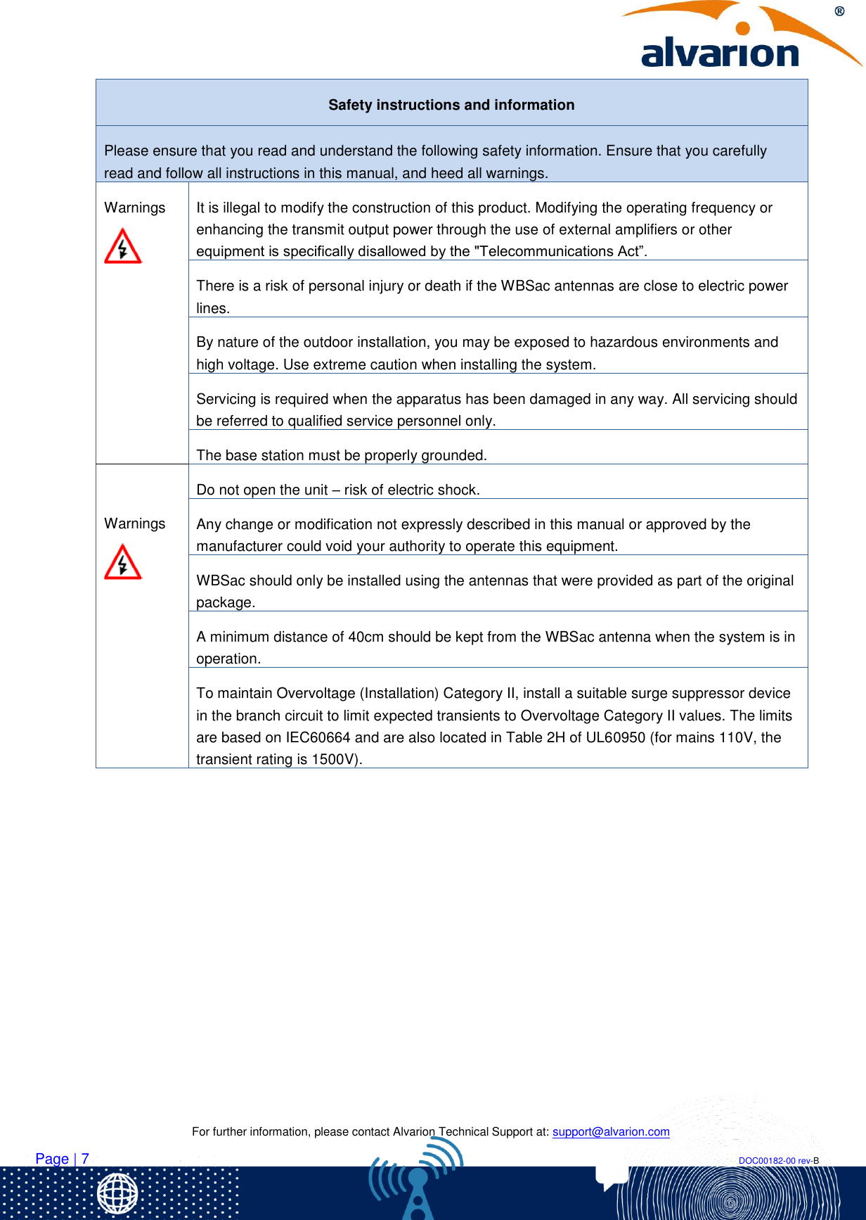
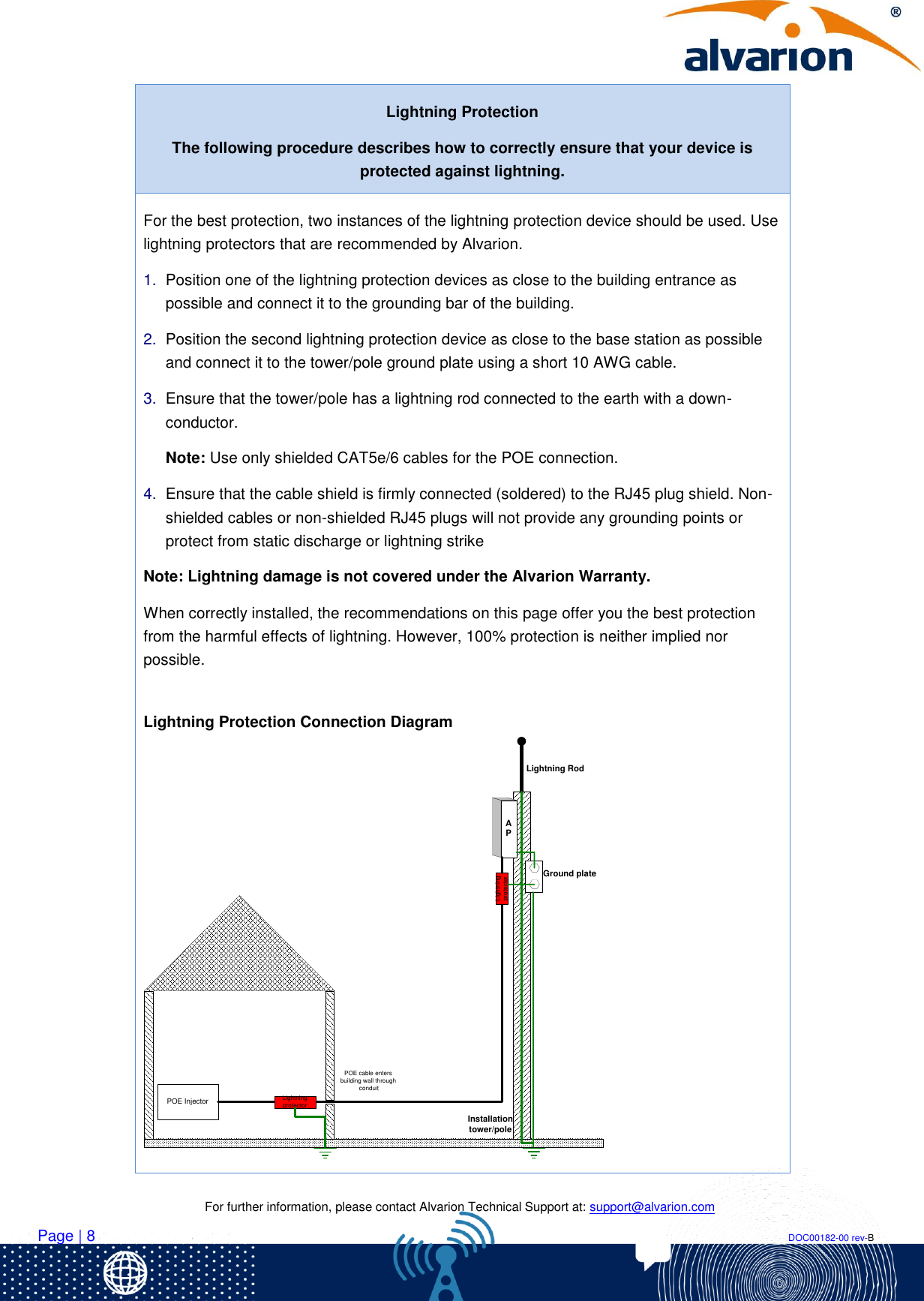
Alvarion Technologies WBSACO12450-1 Outdoor Access Point User Manual Title

Alvarion Technologies Ltd. Outdoor Access Point Title

Users Manual

         WBSAC-2450  QUICK INSTALLATION GUIDE
   For further information, please contact Alvarion Technical Support at: support@alvarion.com Page | 2                                                                                                                                                                DOC00182-00 rev-B Package Content  WBSac-2450 access point   Wall Mount Base  Pole Mount Bracket   Pole mounting steel  band   Wall mounting bots X 4  Mounting screws X 8  5GHz Omni antennas X 2 (for –O products only)  2.4GHz Omni antennas X 2 (for –O products only)  POE adapter  Grounding  screw and cables Additional Equipment Required  Shielded Ethernet cable (outdoor shielded CAT5e/6 4-pair data cable, with RJ45 shielded plugs) Note: Maximum cable length: 100 meters  Lightning protection – use only the devices recommended by Alvarion  1”-2.5” diameter pole (on which to mount the unit in case of pole installation)  Tilting Kit (can be ordered separately when required) Important Information   Warnings  The WBSac access point must be used only with Alvarion-approved components and the antennas provided as part of the original package.  Only experienced installation professionals who are familiar with local building and safety codes and are licensed, wherever applicable, by the appropriate government regulatory authorities, should install outdoor units and antennas. This device requires Professional Installation for compliance with FCC Requirements. (Please refer to page 11 for Installation Instructions).  Modifying the operating frequency or enhancing the transmit output power through the use of external amplifiers or other equipment is illegal.  Note: Certain versions of this device (those with –US extension in their product name) comply with part 15 of the FCC Rules. In these cases, operation is subject to the following two conditions:   This device may not cause harmful interference  This device must accept any interference received, including such interference that may cause unrequired operating effects.
   For further information, please contact Alvarion Technical Support at: support@alvarion.com Page | 3                                                                                                                                                                DOC00182-00 rev-B Mounting WBSac-2450 units support both pole and wall mounting, as shown in the following illustrations.  As the first step of each installation, attach the wall mount base to the back of the unit using 4 of provided mounting screws   Pole Installation  1. Attach the pole mount bracket to the wall mount base using additional 4 provided mounting screws. The pole mount bracket can be attached either vertically        or horizontally
   For further information, please contact Alvarion Technical Support at: support@alvarion.com Page | 4                                                                                                                                                                DOC00182-00 rev-B 2. Insert the provided steel band through the slots of the pole mount bracket, loop it around the pole and tighten the band screw with appropriate screw driver to ensure that the unit is firmly in place.  Note: For best performance of WBSac-2450 unit with integrated sector antennas, the recommendation is to install using a horizontal pole mount, as it offers a wider range of directional adjustment. When installing such unit on a vertical pole - tilting kit may be required.  Tilting kit is an optional accessory giving the ability to tilt the device up to 30°, to achieve better coverage   Wall Installation 1. Mark the location of the mounting holes on the wall surface using wall mount base. 2. Drill a 37 mm deep, 8 mm hole in the markings and hammer the bolts into the openings. 3. Attach the unit and base assembly to the wall using the provided wall mounting bolts and tighten them.
   For further information, please contact Alvarion Technical Support at: support@alvarion.com Page | 5                                                                                                                                                                DOC00182-00 rev-B Grounding Use provided ground screw to attached grounding cable to the device. Warning: You must always install an external grounding wire, as shown below. Ensure that you have completed grounding before you connect power to the WBSac unit        Connecting the antennas This section refers to Omni products (-O) only. Each provided antenna is labeled to show its operating band. 1. Assemble 2.4GHz antennas on the top of the device. 2. Assemble 5GHz antennas on the bottom of the device (near the waterproof POE connector). 3. All the antennas should be tightened by hand.
   For further information, please contact Alvarion Technical Support at: support@alvarion.com Page | 6                                                                                                                                                                DOC00182-00 rev-B Connecting Power and DATA to the WBSac base station  Warning: Before applying power to the device, ensure that all the antennas are connected  1. Connect one end of the Ethernet cable into the LAN port (PoE) of the Access Point (see sealing gland installation chapter bellow) and the other end to the "PoE" port on the PoE injector. 2. Connect the PoE injector in to an electrical outlet using the supplied cable. 3. Connect the second Ethernet cable into the "LAN" port of the PoE injector and the other end to the Ethernet port on the network device.      Sealing gland installation 1. Unscrew sealing gland nut, pull out the rubber bushing and thread Ethernet cable through the sealing plug components.   2. Insert RJ45 plug into POE port on the device, check that sealing washer is in place and install sealing gland base. Tighten sealing gland base to ensure proper sealing. 3. Slide the rubber bushing into sealing gland base  4. Close the sealing gland nut and tighten it until the rubber bushing is compressed, making Ethernet cable sealed.
   For further information, please contact Alvarion Technical Support at: support@alvarion.com Page | 7                                                                                                                                                                DOC00182-00 rev-B Safety instructions and information Please ensure that you read and understand the following safety information. Ensure that you carefully read and follow all instructions in this manual, and heed all warnings. Warnings  It is illegal to modify the construction of this product. Modifying the operating frequency or enhancing the transmit output power through the use of external amplifiers or other equipment is specifically disallowed by the "Telecommunications Act”. There is a risk of personal injury or death if the WBSac antennas are close to electric power lines.  By nature of the outdoor installation, you may be exposed to hazardous environments and high voltage. Use extreme caution when installing the system. Servicing is required when the apparatus has been damaged in any way. All servicing should be referred to qualified service personnel only. The base station must be properly grounded.  Warnings  Do not open the unit – risk of electric shock. Any change or modification not expressly described in this manual or approved by the manufacturer could void your authority to operate this equipment. WBSac should only be installed using the antennas that were provided as part of the original package. A minimum distance of 40cm should be kept from the WBSac antenna when the system is in operation. To maintain Overvoltage (Installation) Category II, install a suitable surge suppressor device in the branch circuit to limit expected transients to Overvoltage Category II values. The limits are based on IEC60664 and are also located in Table 2H of UL60950 (for mains 110V, the transient rating is 1500V).
   For further information, please contact Alvarion Technical Support at: support@alvarion.com Page | 8                                                                                                                                                                DOC00182-00 rev-B Lightning Protection The following procedure describes how to correctly ensure that your device is protected against lightning. For the best protection, two instances of the lightning protection device should be used. Use lightning protectors that are recommended by Alvarion. 1. Position one of the lightning protection devices as close to the building entrance as possible and connect it to the grounding bar of the building. 2. Position the second lightning protection device as close to the base station as possible and connect it to the tower/pole ground plate using a short 10 AWG cable. 3. Ensure that the tower/pole has a lightning rod connected to the earth with a down-conductor. Note: Use only shielded CAT5e/6 cables for the POE connection.  4. Ensure that the cable shield is firmly connected (soldered) to the RJ45 plug shield. Non-shielded cables or non-shielded RJ45 plugs will not provide any grounding points or protect from static discharge or lightning strike Note: Lightning damage is not covered under the Alvarion Warranty.  When correctly installed, the recommendations on this page offer you the best protection from the harmful effects of lightning. However, 100% protection is neither implied nor possible.   Lightning Protection Connection Diagram POE InjectorPOE cable enters building wall through conduitLightning protectorLightning protectorAPGround plateInstallation tower/poleLightning Rod
   For further information, please contact Alvarion Technical Support at: support@alvarion.com Page | 9                                                                                                                                                                DOC00182-00 rev-B  Configuring WBSac Using a Browser 1. In an internet browser, enter the Management IP address of the WBSac unit in the URL navigation field. (Default: http://192.168.1.1, currently supported browsers: Microsoft Internet Explorer, Chrome and Mozilla Firefox.) 2. A log-in screen is displayed. Enter admin in the User Name field, and also enter admin in the password field. 3. Set DHCP server IP address 4. Set Arena controller IP address ( in case using Arena controller)  5. Refer to WBSac-2450 User Manual for a full setup configuration
   For further information, please contact Alvarion Technical Support at: support@alvarion.com Page | 10                                                                                                                                                                DOC00182-00 rev-B  Federal Communication Commission Interference Statement This equipment has been tested and found to comply with the limits for a Class B digital device, pursuant to Part 15 of the FCC Rules. These limits are designed to provide reasonable protection against harmful interference in a residential installation. This equipment generates, uses and can radiate radio frequency energy and, if not installed and used in accordance with the instructions, may cause harmful interference to radio communications. However, there is no guarantee that interference will not occur in a particular installation. If this equipment does cause harmful interference to radio or television reception, which can be determined by turning the equipment off and on, the user is encouraged to try to correct the interference by one of the following measures:  -  Reorient or relocate the receiving antenna. -  Increase the separation between the equipment and receiver. -  Connect the equipment into an outlet on a circuit different from that to which the receiver is connected. -  Consult the dealer or an experienced radio/TV technician for help.  FCC Caution: Any changes or modifications not expressly approved by the party responsible for compliance could void the user's authority to operate this equipment.  This device complies with Part 15 of the FCC Rules. Operation is subject to the following two conditions: (1) This device may not cause harmful interference, and (2) this device must accept any interference received, including interference that may cause undesired operation.  This transmitter must not be co-located or operating in conjunction with any other antenna or transmitter. IMPORTANT NOTE: FCC Radiation Exposure Statement: This equipment complies with FCC radiation exposure limits set forth for an uncontrolled environment. This equipment should be installed and operated with minimum distance 27cm between the radiator & your body.
   For further information, please contact Alvarion Technical Support at: support@alvarion.com Page | 11                                                                                                                                                                DOC00182-00 rev-B FCC- Professional installation instruction 1. Installation personal  This product is designed for specific application and needs to be installed by a qualified personal who has RF and related rule knowledge. The general user shall not attempt to install or change the setting. 2. Installation location  The product shall be installed at a location where the radiating antenna can be kept 27cm from nearby person in normal operation condition to meet regulatory RF exposure requirement. 3. External antenna  Use only the antennas which have been approved by the applicant. The non-approved antenna(s) may produce unwanted spurious or excessive RF transmitting power which may lead to the violation of FCC limit and is prohibited. 4. Installation procedure  Please refer to user’s manual for the detail. 5. Warning  Please carefully select the installation position and make sure that the final output power does not exceed the limit set force in relevant rules. The violation of the rule could lead to serious federal penalty. When professional installer will set work frequency in the GUI to be within UNII-1 band – the software will automatically apply EIRP limit of 21dBm to comply with FCC requirements of Part 15.407(a)(1)(i)  Antenna information: 2.4G: Dipole antenna with 4.6dBi, N-Type for outdoor use. Manufacturer / Model: Senao Networks Inc. / 5718A0136300  5G: Dipole antenna with 6.03dBi, N-Type for outdoor use. Manufacturer / Model: Senao Networks Inc. / 5718A0137300

Navigation menu