AmRoad Technology ARID5101 Video Indoor Station User Manual
AmRoad Technology Inc. Video Indoor Station Users Manual
UserManual.wiki
>
AmRoad Technology
>
ARID5101 User Manual
Users Manual
Navigation menu
Upload a User Manual
Namespaces
Wiki Guide
HTML
PDF
Info
Views
User Manual
Discussion / Help
Navigation


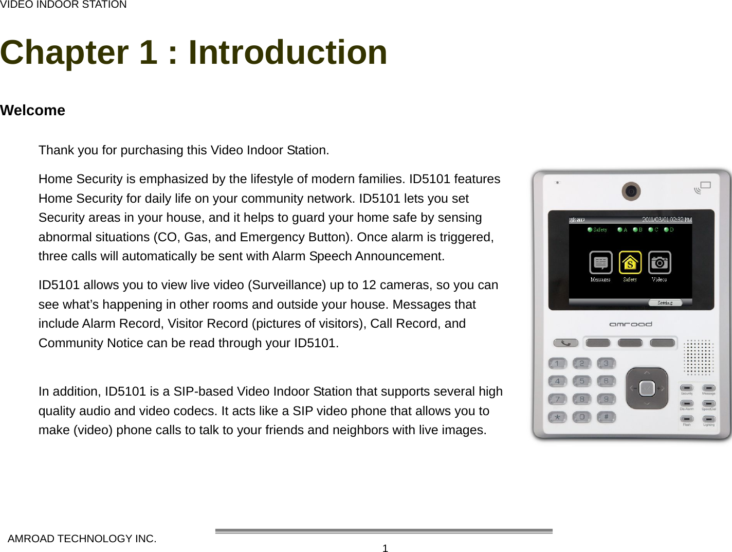


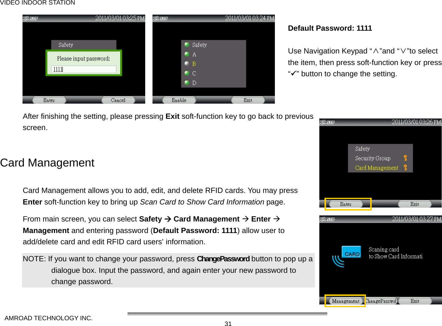
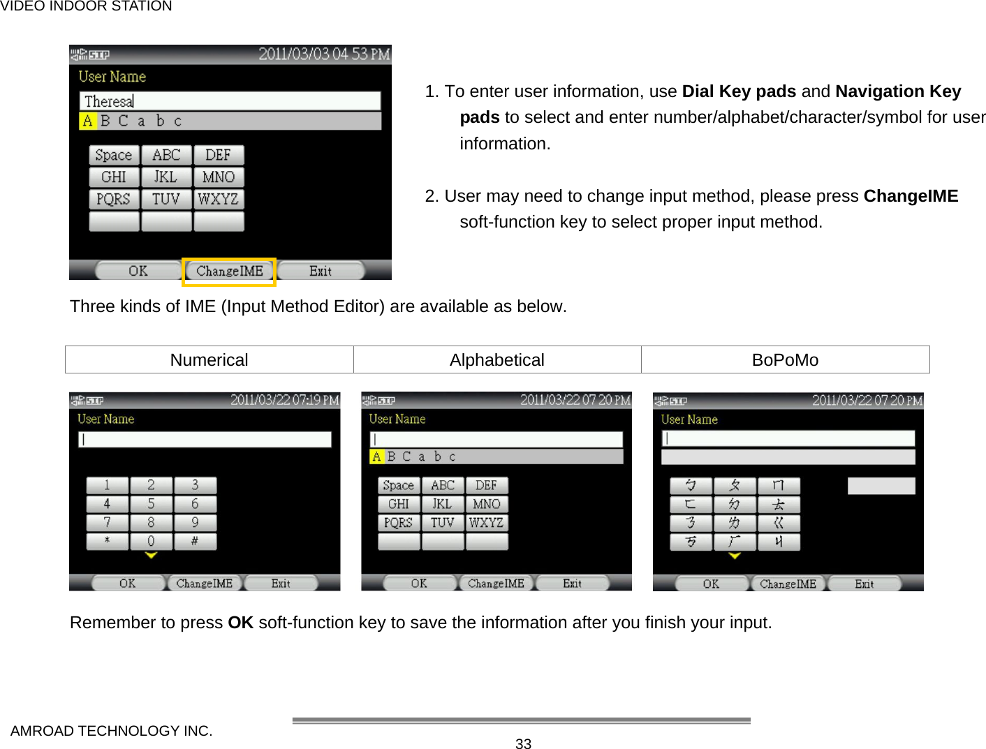
![MANUAL FOR SYSTEM INTEGRATOR AMROAD TECHNOLOGY INC. 32 Adding/Editing User Information of RFID Cards The figures below are the users’ information of RFID cards that have been added to the ID5101. User may edit card information or add new RFID card. There are two ways to add RFID card. The first is to add RFID by scanning new RFID card on card reader on the Scan Card to Add New Card page, and the second is to press Add Card soft-function key to add new Card. The following example shows how to edit card information. To edit card information, press [ManagementÆ Modify] soft-function key to edit card information. Use [ Ç ] and [ È ] navigation keypad to select items and press Edit soft-function key to enter Input Method Editor.](https://usermanual.wiki/AmRoad-Technology/ARID5101/User-Guide-1607757-Page-40.png)
![MANUAL FOR SYSTEM INTEGRATOR AMROAD TECHNOLOGY INC. 34Deleting RFID Card From main screen, you can select Safety Æ Card Management Æ Enter Æ Management and entering password (Default Password: 1111) and use [ Ç ] and [ È ] navigation keypad to select the card that you want to delete. To delete the RFID card, press [ManagementÆ Delete] soft-function key to delete RFID card. Then, the prompt “Please Select Management Action” appears. Press Delete soft-function key again to delete the selected RFID card. Press Delete soft-function key to delete RFID card](https://usermanual.wiki/AmRoad-Technology/ARID5101/User-Guide-1607757-Page-42.png)
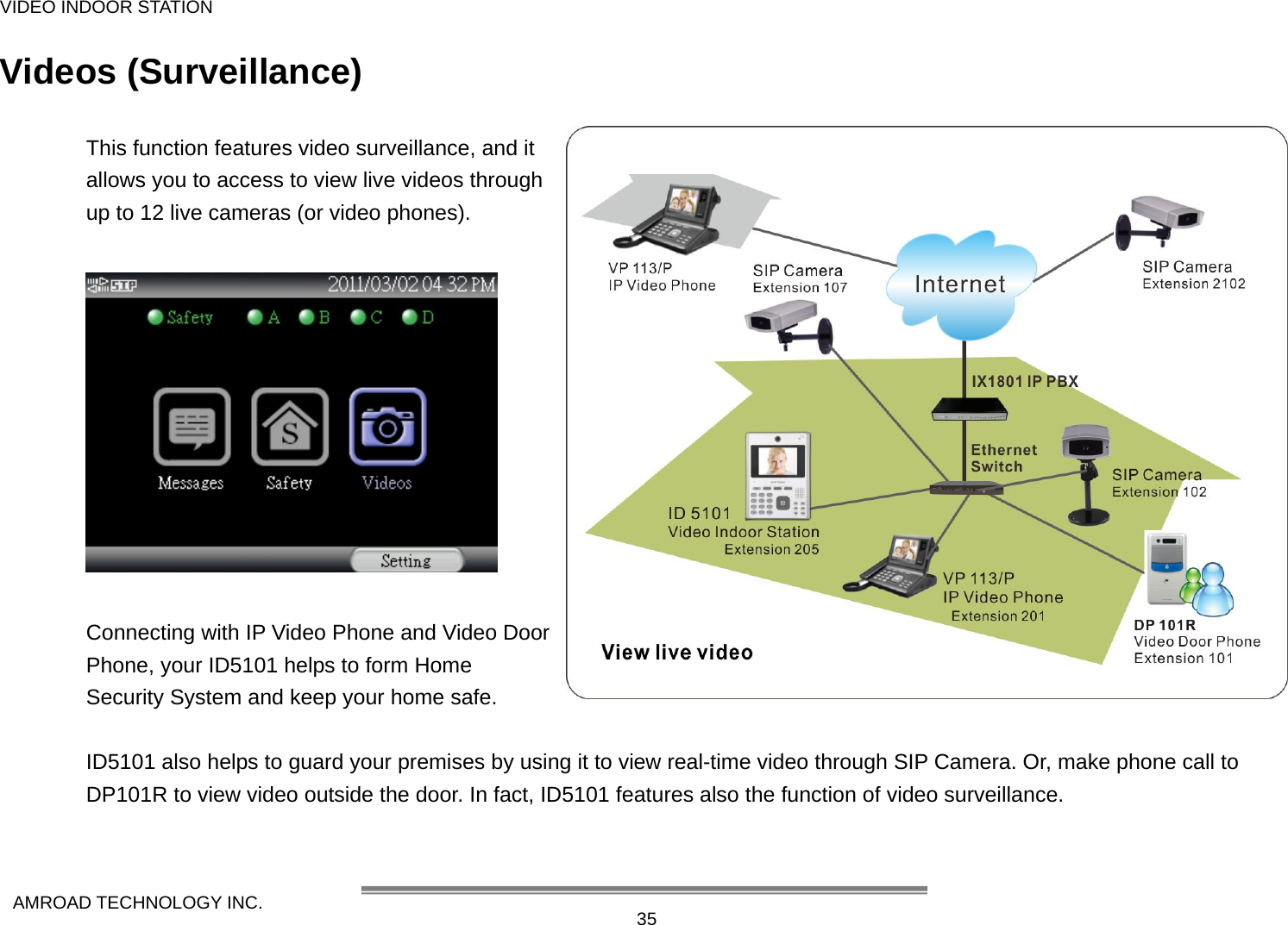
![MANUAL FOR SYSTEM INTEGRATOR AMROAD TECHNOLOGY INC. 36 Live Video From main screen, you can select Videos and press Enter “9” key to enter the View screen. (Refer to the right Figure) To view live video at other room or outside the house, please select site or location by using [ Ç ] and [ È ] keys, and then press Enter key [ 9 ] or press View soft-function key. NOTE: The connections with other video devices are set through WEB UI. Enabling remote viewing, your ID5101 needs to connect with other cameras/video door phones. Then, select the SIP Camera, Video Door Phone you want to view through, press View soft-function key to see what’s happening. Press Change View soft-function key to view picture-in-picture video, and you can change the video and ID5101’s view in turn.](https://usermanual.wiki/AmRoad-Technology/ARID5101/User-Guide-1607757-Page-44.png)
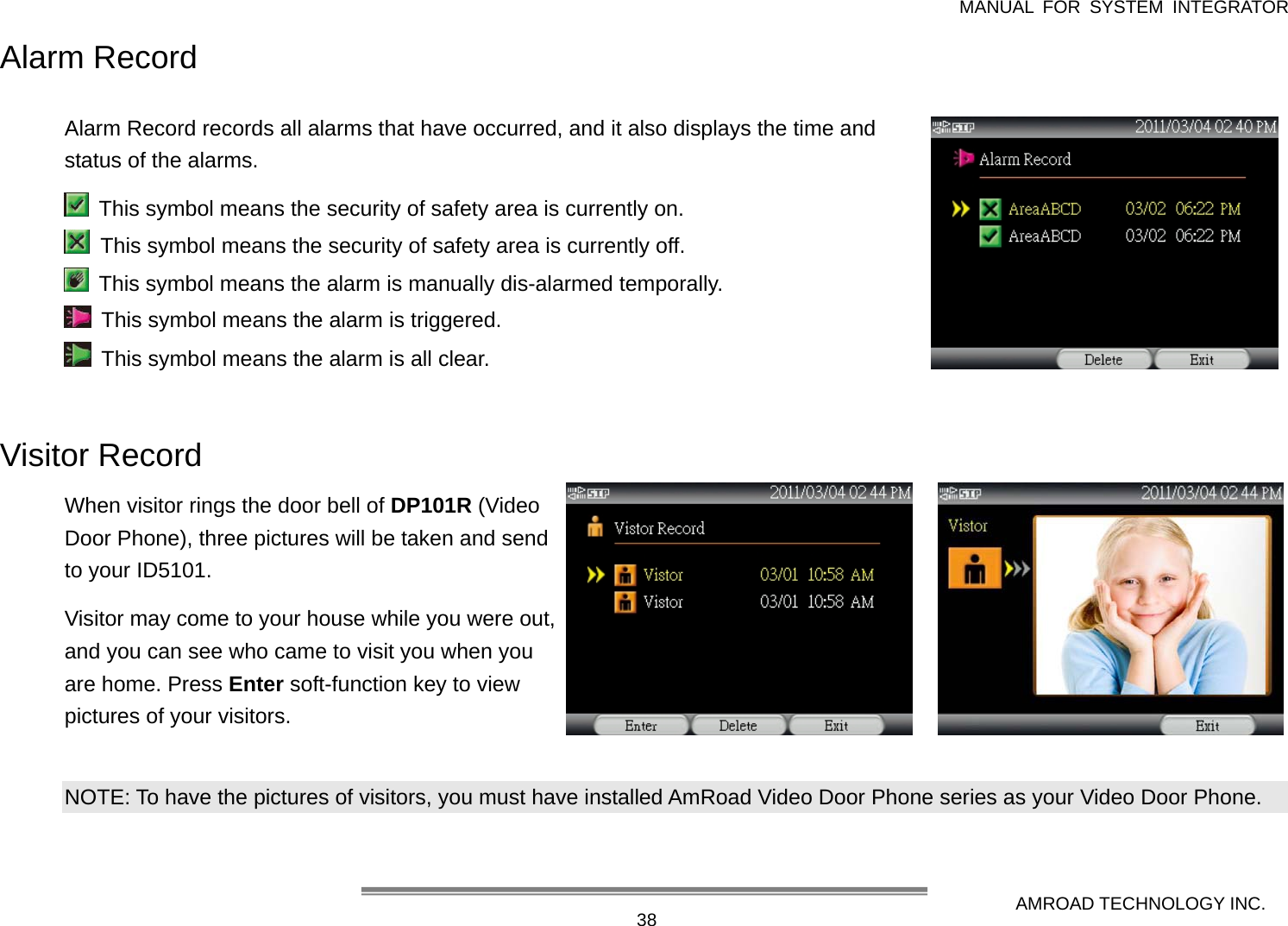
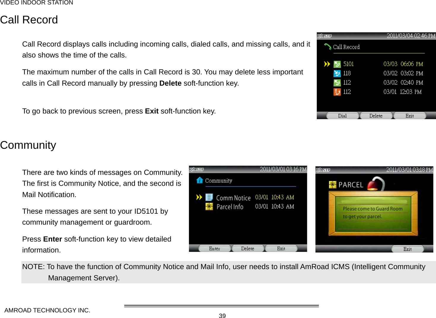
![VIDEO INDOOR STATION AMROAD TECHNOLOGY INC. 37 Massages This feature provides you important and useful messages while you were out and you are home now. They include Alarm Record, Pictures of Visitors, Call Record, and, Community Notice. Select Massage and press Enter key [ 9 ] to enter the Massage screen. The messages contain four items, and each item has record massage(s) and unread massage(s). z Alarm Record: Each alarm that has occurred will be recorded (maximum 30 alarms record). z Visitor Record: Each visitor will be taken 3 pictures (maximum 15 visitors). You can see pictures of visitors here. z Call Record: All incoming calls, dialed calls, and missing calls will be recorded here (maximum 30 calls record). z Community: This item acts like Community Notice. Community notice or Mail notice may be sent from or community management or guard room.](https://usermanual.wiki/AmRoad-Technology/ARID5101/User-Guide-1607757-Page-45.png)
![VIDEO INDOOR STATION AMROAD TECHNOLOGY INC. 41Chapter 5 : Setting Up The ID5101 This chapter describes how to set up your Video Indoor Station. You may press Setting soft-function key to enter this Setting page. There are 8 major items for configuration: z System Setting z Video Setting z Audio Setting z Network Setting (Password protected) z SIP Setting (Password protected) z Streaming Setting (Password protected) z Service Setting (Password protected) z Screen Saver Setting You may use [ Ç ] and [ È ] keys to select preferred item, and then press Enter key [ 9 ] or press Enter soft-function key to take further actions. NOTE: 1. Network Setting, SIP Setting, Stream Setting, and Service Setting are protected by password. (Default password: 1234) 2. This setting password is different from Security password.](https://usermanual.wiki/AmRoad-Technology/ARID5101/User-Guide-1607757-Page-49.png)
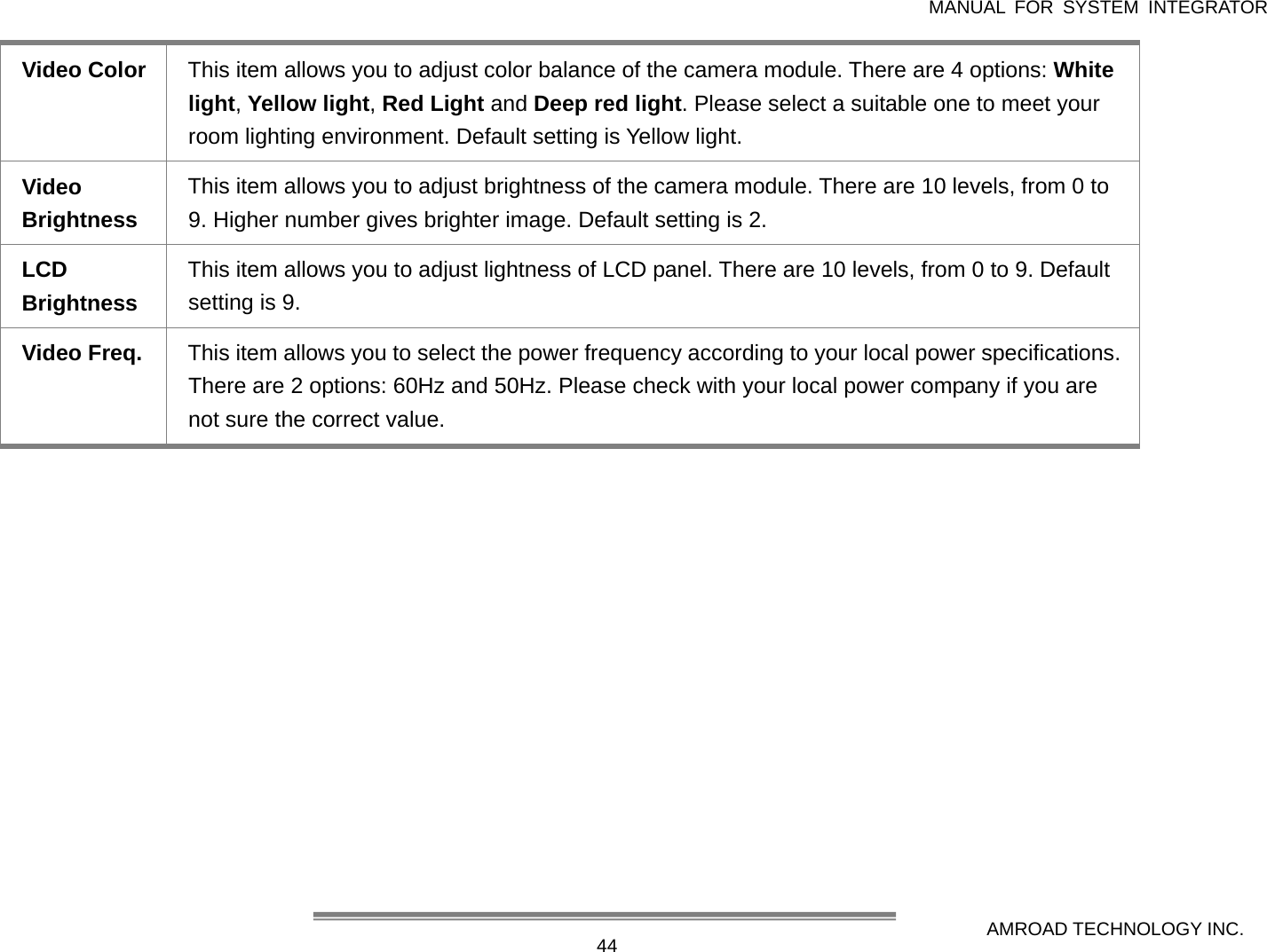
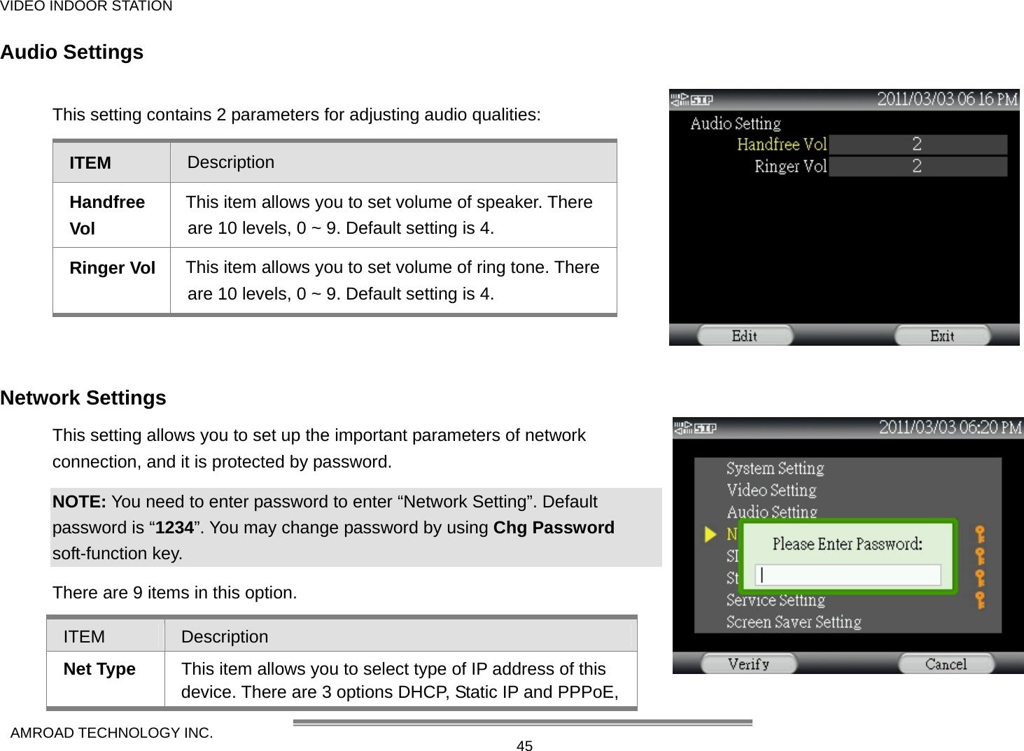
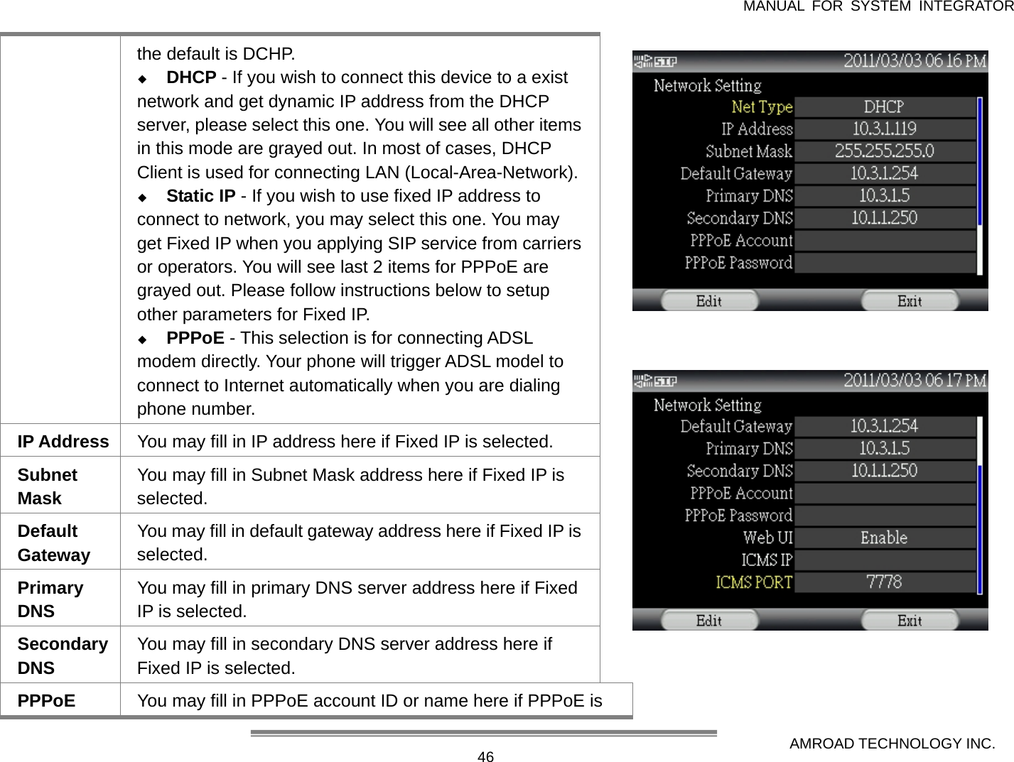
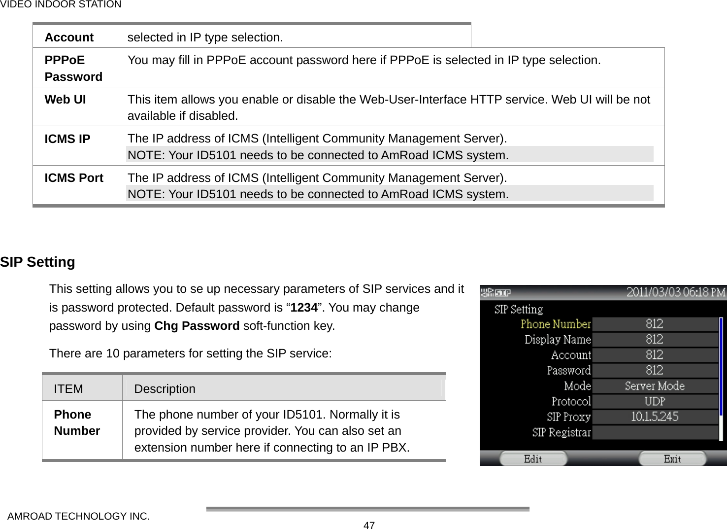
![MANUAL FOR SYSTEM INTEGRATOR AMROAD TECHNOLOGY INC. 42System Settings This setting contains some basic system settings of this device. These settings allow general users to set up this Video Indoor Station according to their preferences. ITEM Description Firmware Version The current firmware version of your Video Indoor Station Device ID This ID is a unique number giving by manufacturer to identify this device on networks. It is fixed and not revisable. Device Name This item allows user to give a name to this device. You can use this name to identify this particular device if you have more than one Video Indoor Station on the same network. You can rename it by using Edit soft-function key. Date & Time You can input your local date and time in this field. Date Format You can select preferred date format at this field. There are 3 formats available: YYYY/MM/DD, MM/DD/YYYY and DD/MM/YYYY. Use [ Ç ] and [ È ] keys to select preferred one, then press OK to confirm selection. Time Format You can select preferred time format at this field. There are 2 formats available: 12 hours and 24 hours system. You may use [ Å ] and [ Æ] keys to select preferred format.](https://usermanual.wiki/AmRoad-Technology/ARID5101/User-Guide-1607757-Page-50.png)
![VIDEO INDOOR STATION AMROAD TECHNOLOGY INC. 43Time Zone You may select preferred time zone in this field. This Time Zone is based on GMT (Greenwich Mean Time) system. There are total 33 selections, from GMT-12:00 to GMT+13:00. You may use [ Ç ] and [ È ] keys to select your Time Zone. For example: Taipei is GMT+08:00 Day Light Saving This item allows you to enable or disable “Day-Light- Saving” function. This phone will adjust the time automatically according to globe standard if enabled. Video Settings This setting contains 6 parameters that you may use to adjust video streaming and quality: ITEM Description Default Video This item allows you enable or disable video streaming. Phone calls will be voice only if “Off” is selected. Default setting is On. Video Quality This item allows you to select preferred video quality. There are 5 options: Excellent, Good, Average, Acceptable and Worst. Please note that better quality creates higher bit-rate and requires larger bandwidth. NOTE: We strongly suggest that you select Average for your setting because Excellent is for static video and Low is for motion picture.](https://usermanual.wiki/AmRoad-Technology/ARID5101/User-Guide-1607757-Page-51.png)