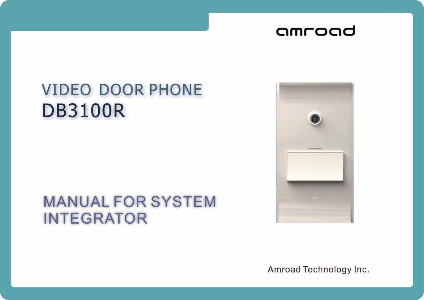
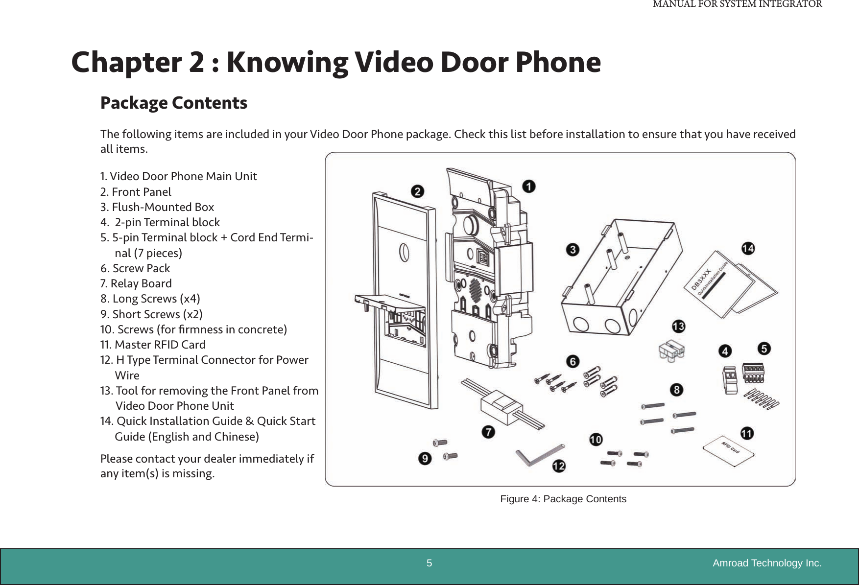
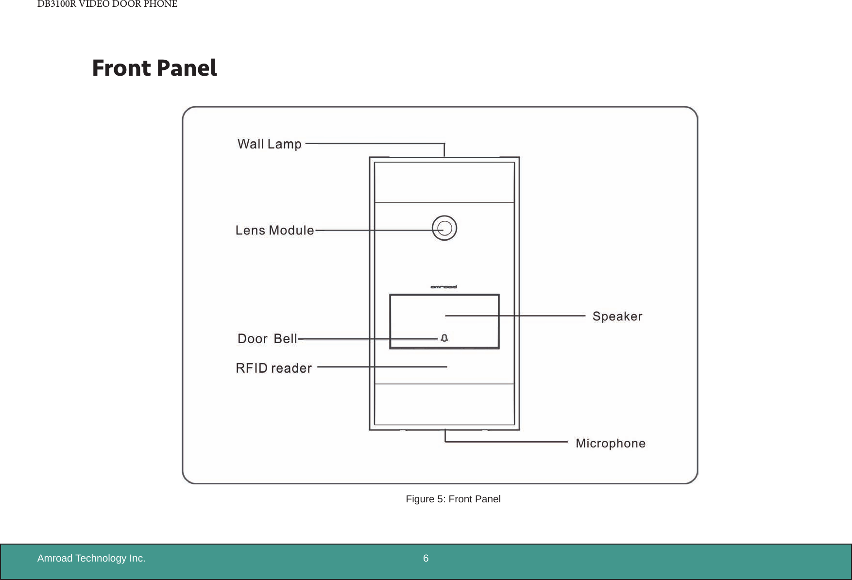
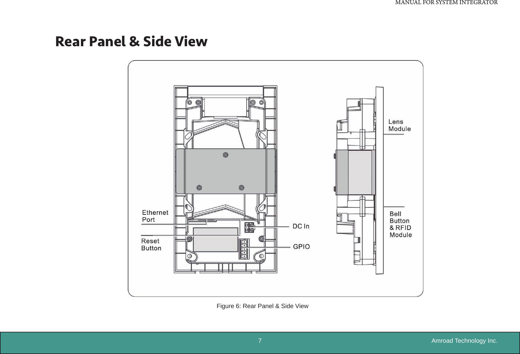
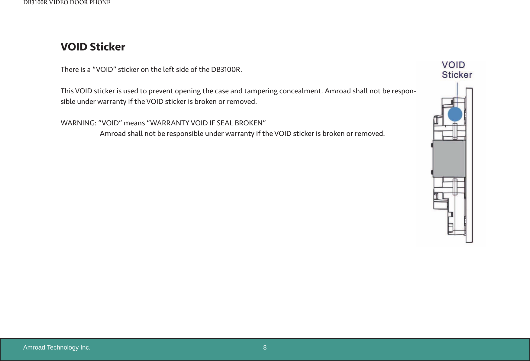
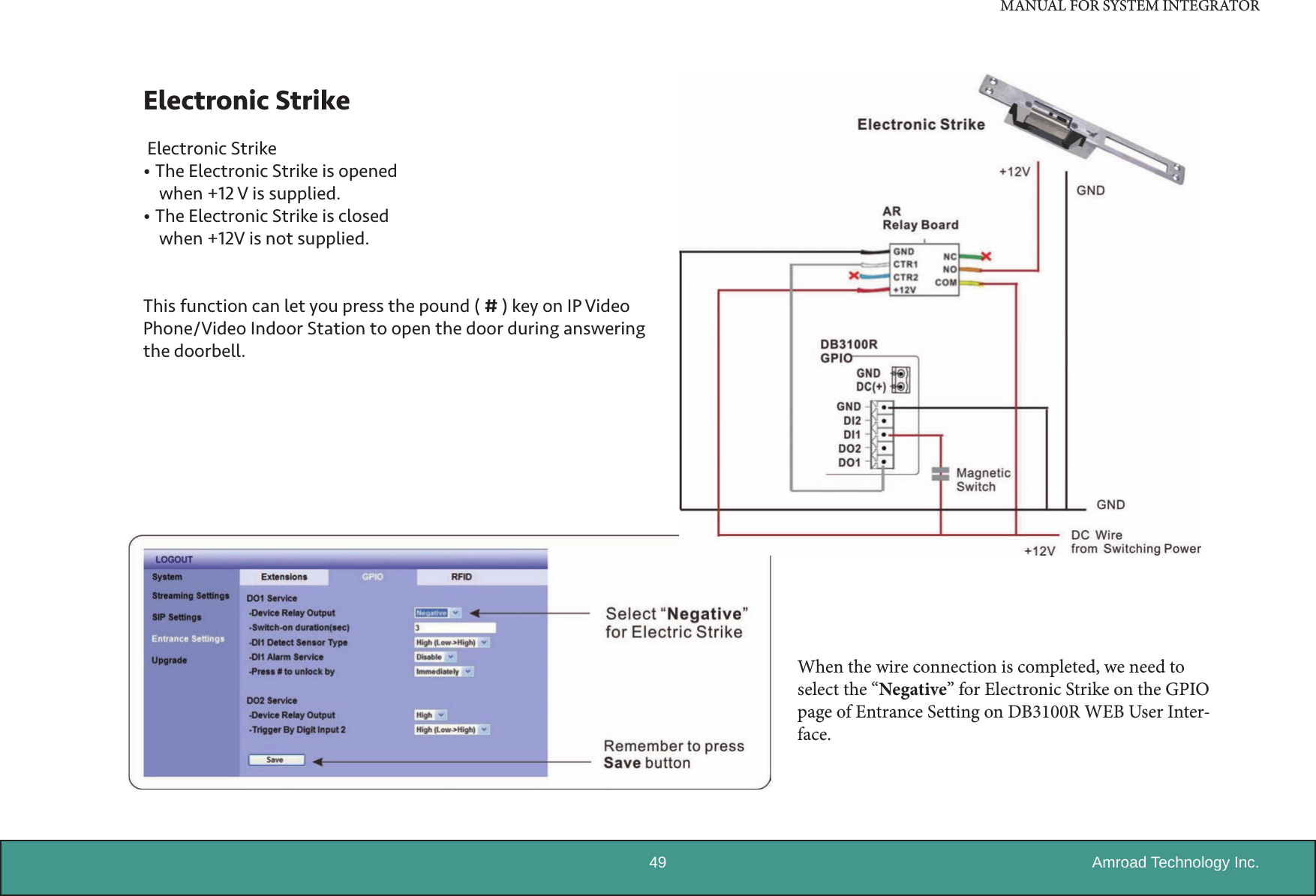
AmRoad Technology DB3100R Video door phone User Manual
AmRoad Technology Inc. Video door phone Users Manual
UserManual.wiki
>
AmRoad Technology
>
DB3100R User Manual
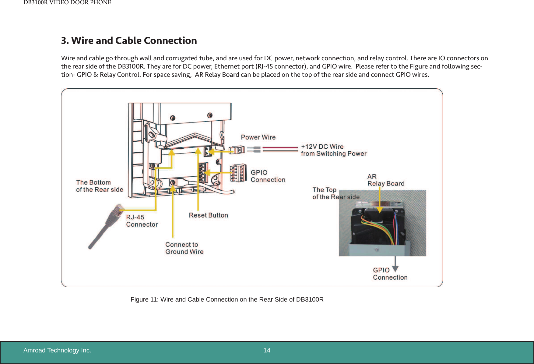
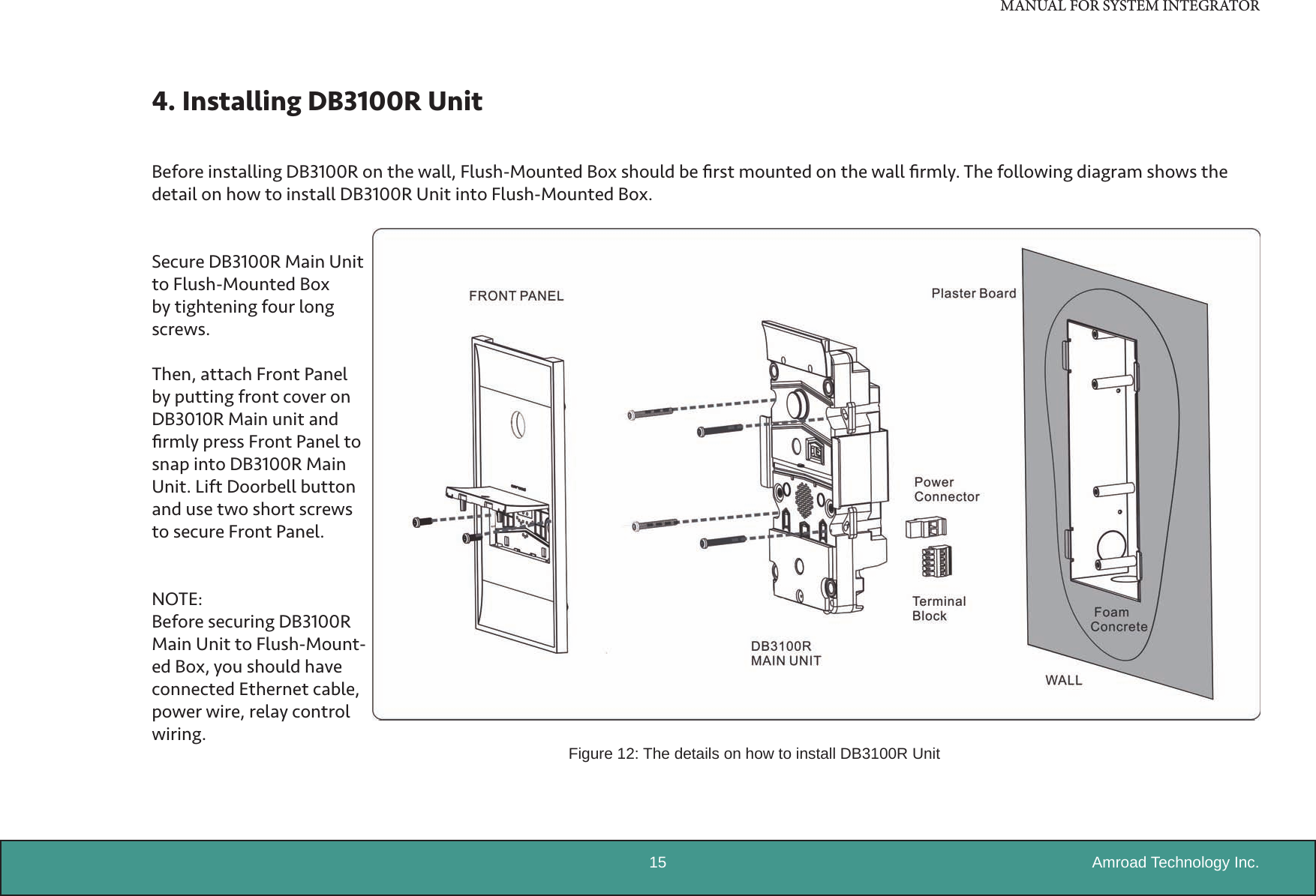
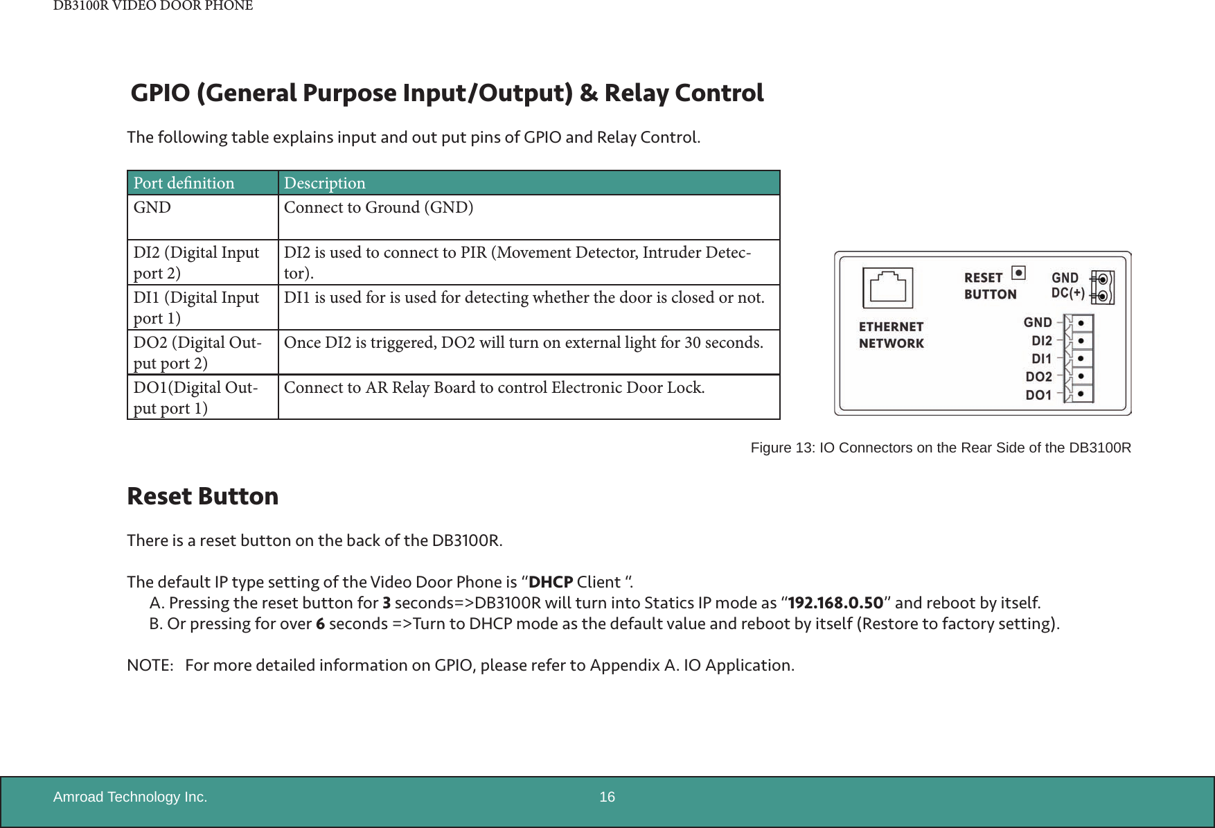
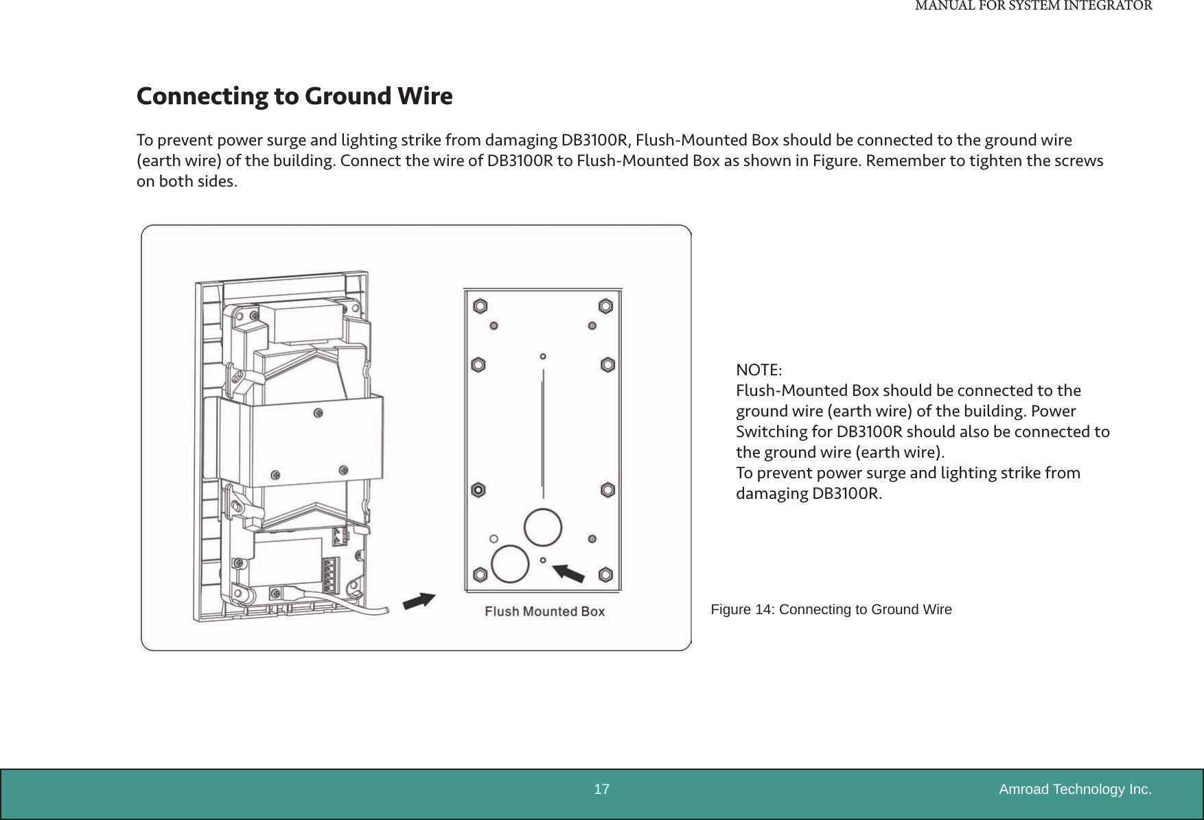
Users Manual
Navigation menu
Upload a User Manual
Namespaces
Wiki Guide
HTML
PDF
Info
Views
User Manual
Discussion / Help
Navigation