AmRoad Technology DB3100R Video door phone User Manual
AmRoad Technology Inc. Video door phone Users Manual
Users Manual

Copyright
© 2012 Amroad Technology Inc.
All Rights Reserved. No part of this publication may be reproduced, transmitted, transcribed, stored in a retrieval system or translated into any language in any
form or by any means without the express written permission of Amroad Technology Inc. To obtain consent, write to the attention of Amroad Technology Inc.
Document No. DB3100R 2012-0402
www.amroad.com.tw
DISCLAIMER
Amroad reserves the right to change product specification without prior notice.
Changes may be made to the information in this publication without obligation to notify. Amroad shall not be liable for technical or editorial errors contained
herein.
TRADE MARKS
Amroad logo is copyright of Amroad Technology Inc. All other products, services or trade marks mentioned in this document are the property of their respective
owners, companies or organizations.
Contents
Copyright
Chapter 1: Introduction 1
Welcome 1
General Application of Door Entry System 2
Unit in Luxury Apartment Building 2
Use of SIP 3
Chapter 2 : Knowing Video Door Phone 5
Package Contents 5
Front Panel 6
Rear Panel & Side View 7
Dimensions 8
Chapter 3 : Installing Video Door Phone 9
Suggested Installation Position 9
View Angle 9
Installion Procedures 10
1. Prepare Flush-Mounted Box 10
2. Secure Flush-Mounted Box on Steel Frame 11
3. Wire and Cable Connection 12
4. Installing DB3100R Unit 13
Reset Button 14
Connecting to Ground Wire 15
Chapter 4 : Use of the Video Door Phone 17
Making Calls From Video Door Phone 17
Answering Calls on IP Video Phone 17
Open the Door 17
Common Controls 17
DB3100R RFID Card Usage 18
Issue Master RFID Card First Time 18
Issue a New Card with Master RFID Card: 18
Wall Lamp and RFID LED Indicators 19
Status LED 20
Audio Announcement 21
Chapter 5 : Configuring Video Door Phone 23
Finding Video Door Phone on Networks 23
Entering Web User Interface 24
System - Basic Settings 25
System - Networking Settings 26
System Login Name 27
System Reboot 27
Streaming Settings – Video 28
Streaming Settings – Audio 30
SIP Settings 31
Entrance Settings – Extensions 33
Entrance Settings – GPIO 36
Entrance Settings –RFID 38
Upgrade –Upgrade 40
Upgrade –Configuration 41
AR APS 42
Functions Performed by the IP-PBX (Compatible with Amroad IP-PBX) 43
Appendix A : IO Application 45
Electronic Lock 45
Wiring Connection and Web Page Setup 45
Electronic Bolt 45
Electronic Strike 47
Appendix B : Regulatory Information 49
FCC STATEMENT 49
FCC Radiation Exposure Statement 49
CE DECLARATION OF CONFORMITY (EUROPE) 50

Amroad Technology Inc.1
MANUAL FOR SYSTEM INTEGRATOR
Chapter 1: Introduction
Welcome
Thank you for choosing this Video Door Phone. This device is designed to work as Video Door Phone of inside large building to form a
SIP-based door entry system. Besides taking advantages of IP technologies, this device links to other SIP devices. It will work with most IP
PBX systems supporting audio and video, and it can be configured via a web interface.
This product contains following main features:
• Talk to visitors with real time video and voice on IP Video Phone or Video Indoor Station
• SIP 2.0 (RFC3261) Compliant
• Support H.263 video format.
• Support G.711 audio formats.
• RFID card reader (ISO14443A/13.56MHz (MIFARE Standard) with embedded RFID card database
• Support Peer-to-Peer Mode
• Build-in wide angle lens
• Wall Lamp (White LEDs)
• Build-in speaker and microphone.
• Scan RFID card to open the door
• Support PoE (Power over Ethernet, 802.3af) module (External power supply AC 48V In)
• Web user interface for configuration and management.
Please read this user guide before installing the device. Please contact your dealers or system integrators if you have questions.
Figure 1: DB3100R
Amroad Technology Inc. 23
DB3100R VIDEO DOOR PHONE
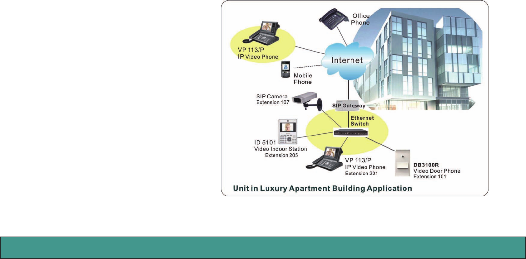
General Application of Door Entry System
There are two major series of Video Door Phone: community series and single unit series. They are applied on dierent conditions.
DB3100R is designed for Unit in Luxury Apartment Building Application. It can work with IPBX servers to communicate with other
SIP-based devices. DB3100R works not only
as an intercom system but is also able to
integrate RFID card reader and connect to
other SIP devices to form a complete door
entry system.
Figure 2: Unit in Luxury Apartment Building Application
Unit in Luxury Apartment
Building
Unit in Luxury Apartment Building is illus-
trated. Please see Figure 2 for reference.
• Using a home IP PBX to connect all SIP-
based devices.
• Communicate with each device simply
with extension numbers.
• Connect to SIP VoIP services via Inter-
net.
Amroad Technology Inc.3
MANUAL FOR SYSTEM INTEGRATOR
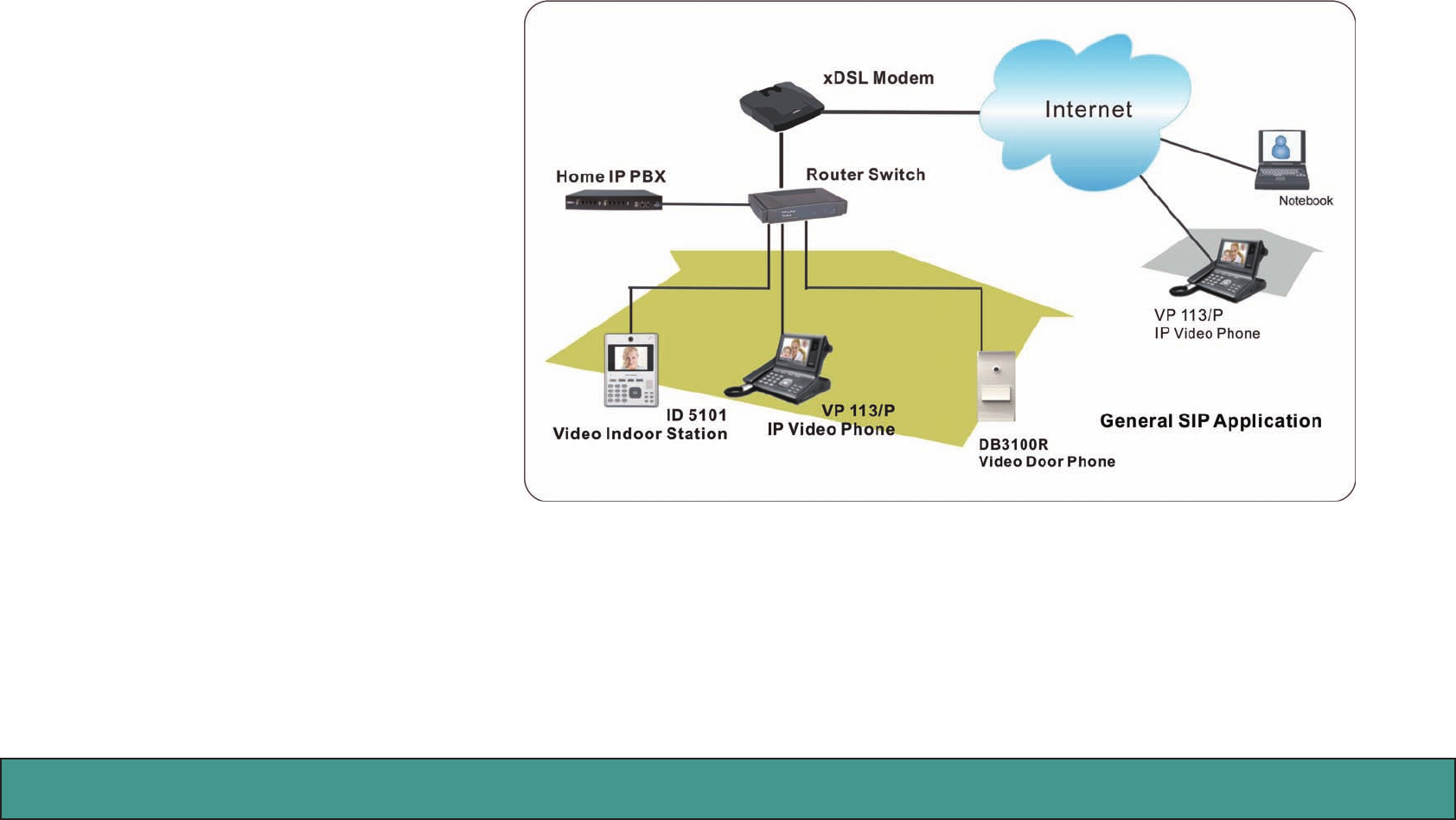
Use of SIP
SIP, initial of Session-Initiation-Proto-
col, it is an application-layer control
(signaling) protocol for creating, modi-
fying, and terminating sessions with
one or more participants. These ses-
sions include Internet telephone calls,
multimedia distribution, and multime-
dia conferences. In short, SIP is a most
commonly used protocol that has been
used to interconnect SIP Enabled PBXs
and/or SIP User Agents to each other
to establish voice and video sessions
between SIP based devices over IP
Network.
There are few typical applications of
SIP products, please refer to Figure 4:
•RingtheDoorBellfromVideoDoor
Phone (DB3100R) to IP Video Phone
(VP113/P)/Video Indoor Station
(ID5101)/IPC Softphone
•MakeaDB3100Rlive-videoviewphonecallfromIPCSoftphone/IPVideoPhone/VideoIndoorstation.
•MakeavideophonecallfromID5101VideoIndoorStationtoVP113IPvideophone.
Figure 3: General SIP Application

Amroad Technology Inc. 45
DB3100R VIDEO DOOR PHONE
Amroad Technology Inc.5
MANUAL FOR SYSTEM INTEGRATOR
Chapter 2 : Knowing Video Door Phone
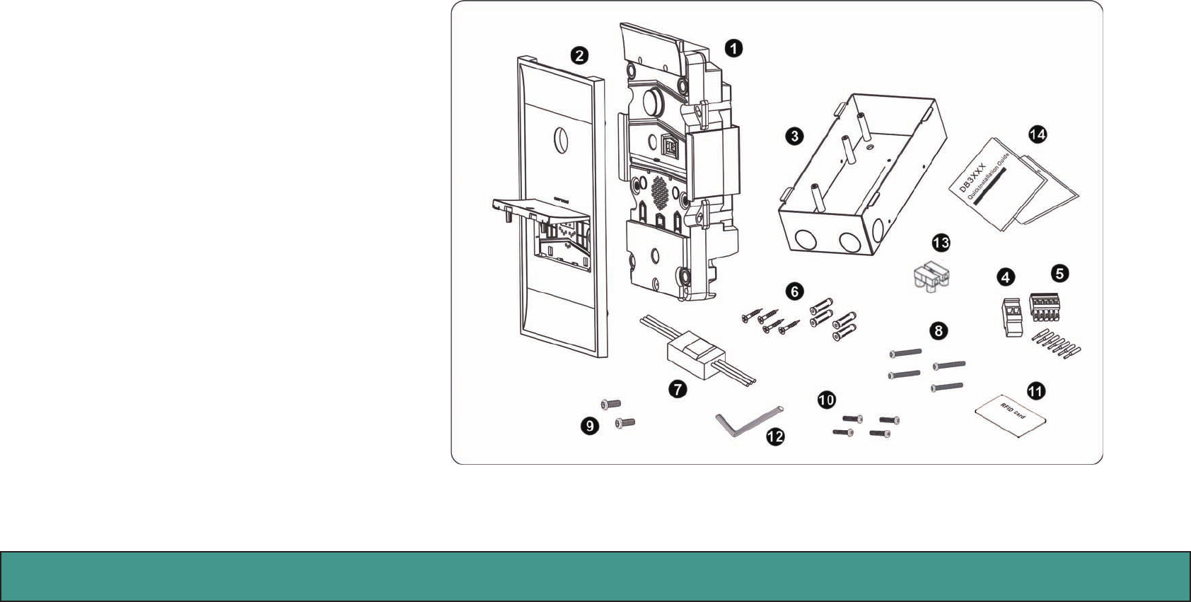
Package Contents
The following items are included in your Video Door Phone package. Check this list before installation to ensure that you have received
all items.
1. Video Door Phone Main Unit
2. Front Panel
3. Flush-Mounted Box
4. 2-pin Terminal block
5. 5-pin Terminal block + Cord End Termi-
nal (7 pieces)
6. Screw Pack
7. Relay Board
8. Long Screws (x4)
9. Short Screws (x2)
10. Screws (for firmness in concrete)
11. Master RFID Card
12. H Type Terminal Connector for Power
Wire
13. Tool for removing the Front Panel from
Video Door Phone Unit
14. Quick Installation Guide & Quick Start
Guide (English and Chinese)
Please contact your dealer immediately if
any item(s) is missing.
Figure 4: Package Contents
Amroad Technology Inc. 67
DB3100R VIDEO DOOR PHONE
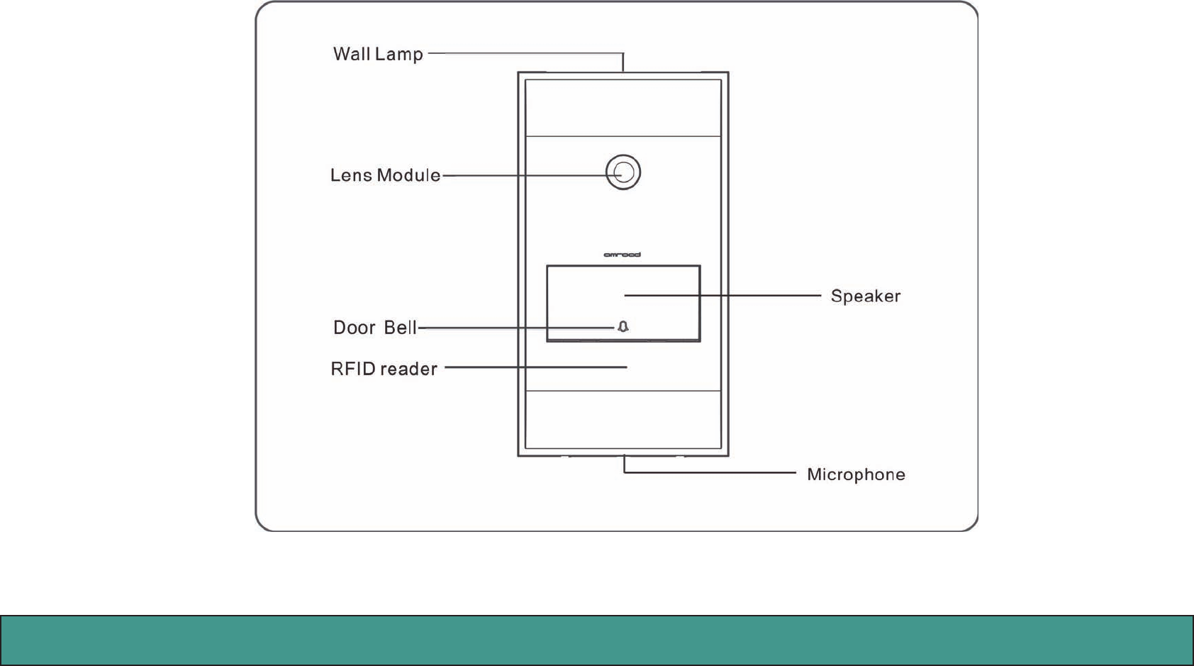
Front Panel
Figure 5: Front Panel
Amroad Technology Inc.7
MANUAL FOR SYSTEM INTEGRATOR
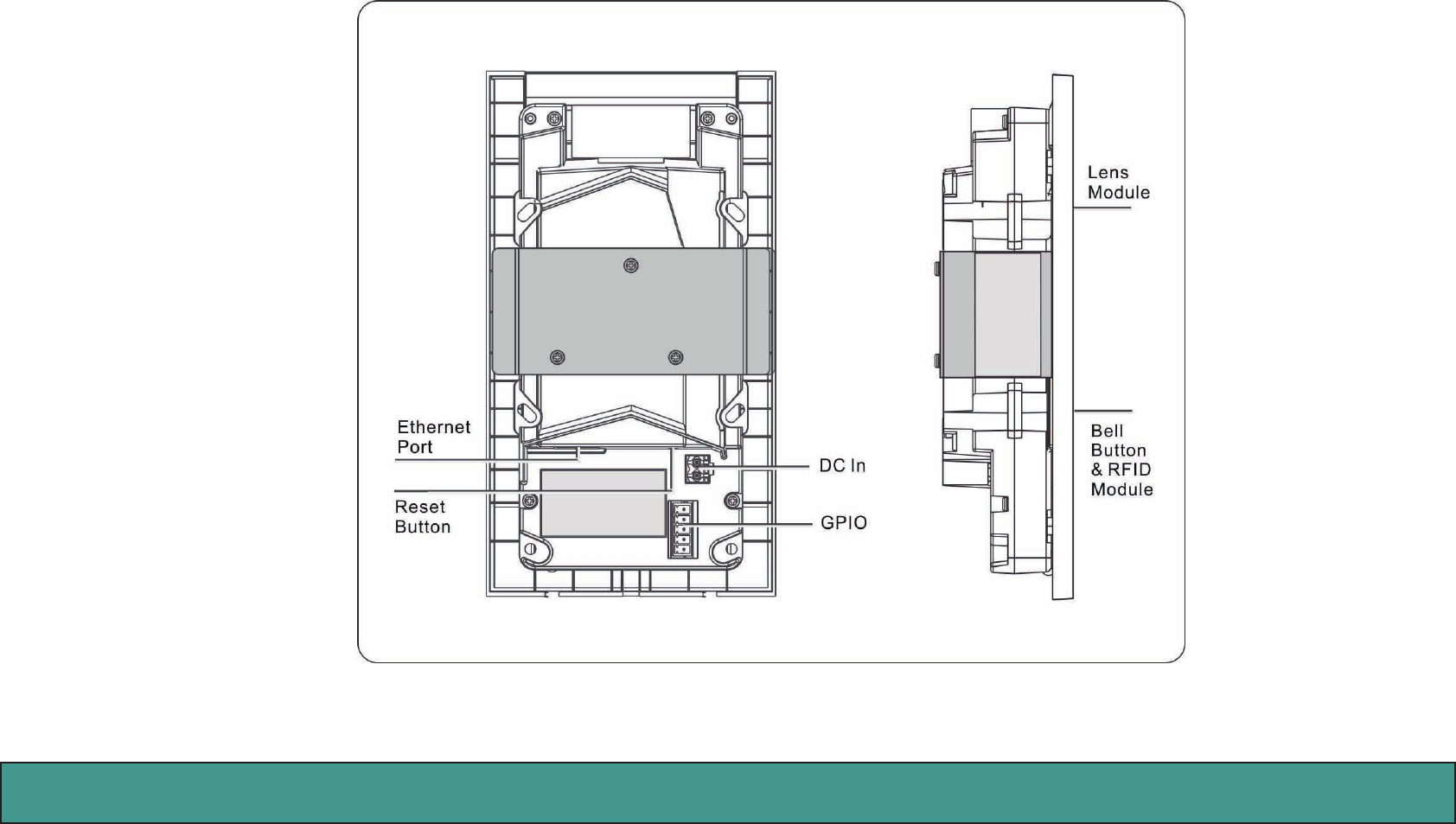
Rear Panel & Side View
Figure 6: Rear Panel & Side View
Amroad Technology Inc. 89
DB3100R VIDEO DOOR PHONE
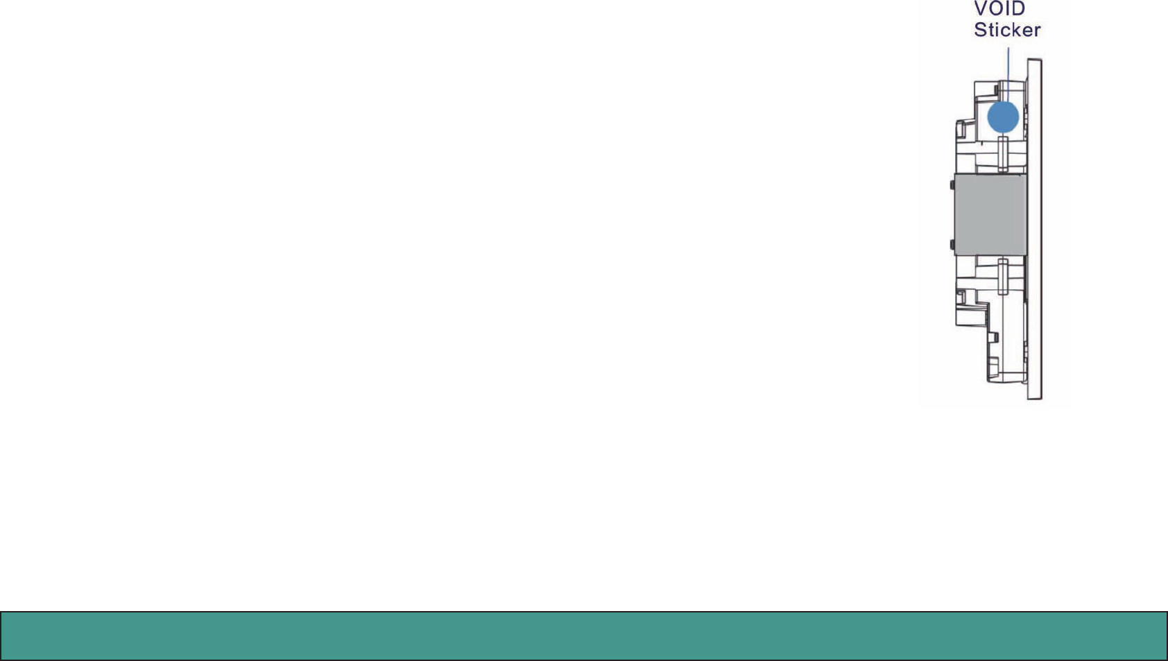
VOID Sticker
There is a “VOID” sticker on the left side of the DB3100R.
This VOID sticker is used to prevent opening the case and tampering concealment. Amroad shall not be respon-
sible under warranty if the VOID sticker is broken or removed.
WARNING: “VOID” means “WARRANTY VOID IF SEAL BROKEN”
Amroad shall not be responsible under warranty if the VOID sticker is broken or removed.
Amroad Technology Inc.9
MANUAL FOR SYSTEM INTEGRATOR
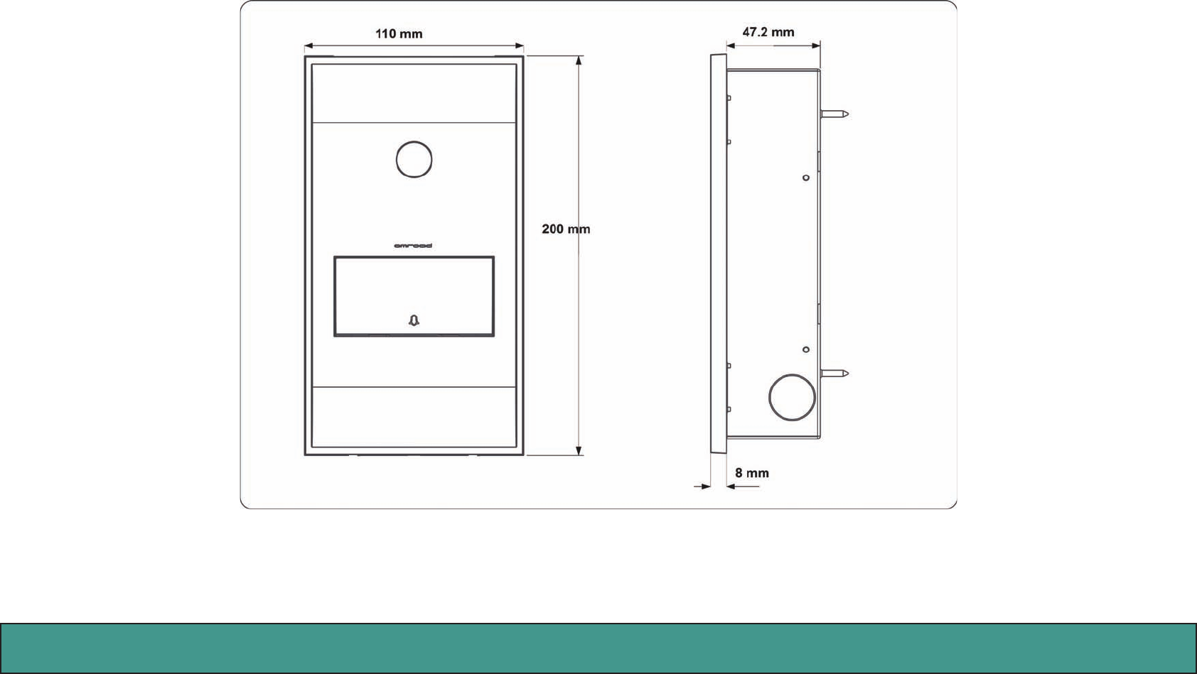
Dimensions
Figure 7: Dimensions

Amroad Technology Inc. 10 11
DB3100R VIDEO DOOR PHONE
Amroad Technology Inc.11
MANUAL FOR SYSTEM INTEGRATOR
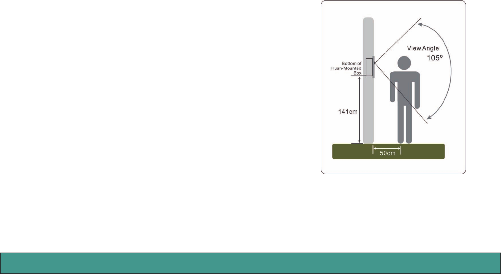
Figure 8: Suggested Installation Position
Chapter 3 : Installing Video Door Phone
Suggested Installation Position
The view angle of the lens module is limited, so the installation position for Video
Door Phone is crucial. The video door phone comes with a Flush-Mounted Box. In order
to get a better view and the view angle of this door phone, the height of the bottom
of the Flush-Mounted Box is suggested about 141 cm far away from the ground (please
also refer to the diagram in the following sections) according to building conditions.
Please refer to the Figure.
View Angle
The Lens module of this device is able to see color images. To view clear live-video
images from IP Video Phone or Video Indoor Station, the view angle of this video door
phone should be less than 105o.
NOTE: The height of the camera lens is suggested at the distance of 155 cm above the
oor.
Amroad Technology Inc. 12 13
DB3100R VIDEO DOOR PHONE
Installion Procedures
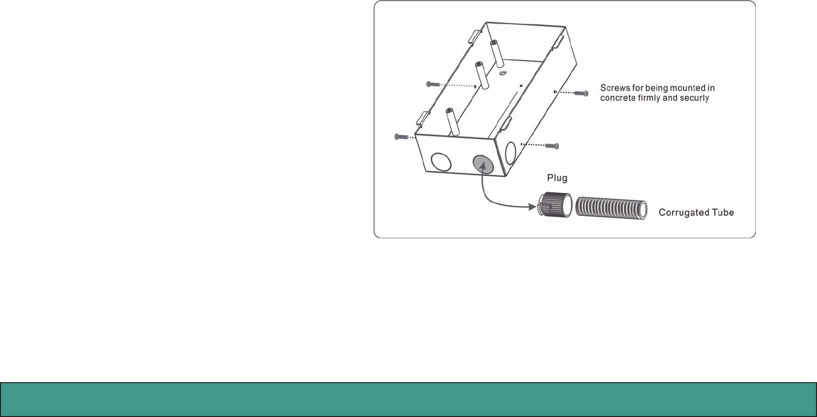
1. Prepare Flush-Mounted Box
Before installing the Flush-Mounted Box, you can
fasten four screws on Flush-Mounted Box as shown in
Figure. This will make Flush-Mounted Box be mounted
on the wall more firmly and securely after grouting
foam concrete.
Use a Plug to connect Corrugated Tube to Flush-
Mounted Box. The corrugated tube allows cable and
wirings to pass through. The cable and wirings are Eth-
ernet cable, DC power, and Relay control.
Figure 9: Tighten four Screws and Connect Corrugated Tube
Amroad Technology Inc.13
MANUAL FOR SYSTEM INTEGRATOR
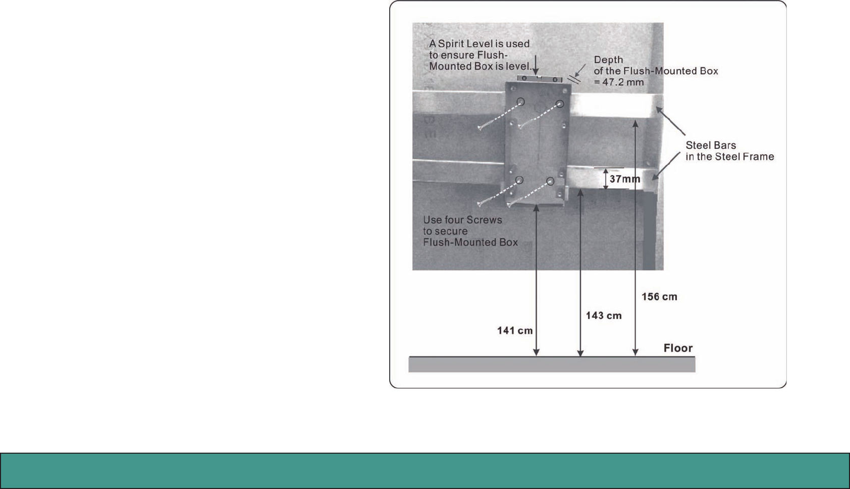
2. Secure Flush-Mounted Box on Steel Frame
Before attaching Plaster Board and grouting Foam
Concrete on the wall, it’s necessary to secure Flush-
Mounted Box on Steel Frame.
The heights of the Steel Bars for installing Flush-
Mounted Box are suggested as shown in Figure.
The height between the bottom of the Flush-Mounted
Box and oor is 141 cm. And the depth of the Flush-
Mounted Box is 47.2mm.
Use four Drill Screws to secure Flush-Mounted Box on
Steel Bars in the Steel Frame. At the same time, a bub-
ble level is used to ensure Flush-Mounted Box is level.
Figure 10: Secure Flush Mounted Box to Steel Frame
Amroad Technology Inc. 14 15
DB3100R VIDEO DOOR PHONE
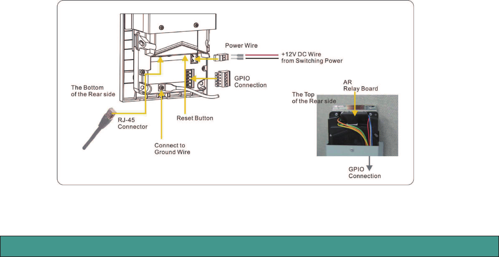
3. Wire and Cable Connection
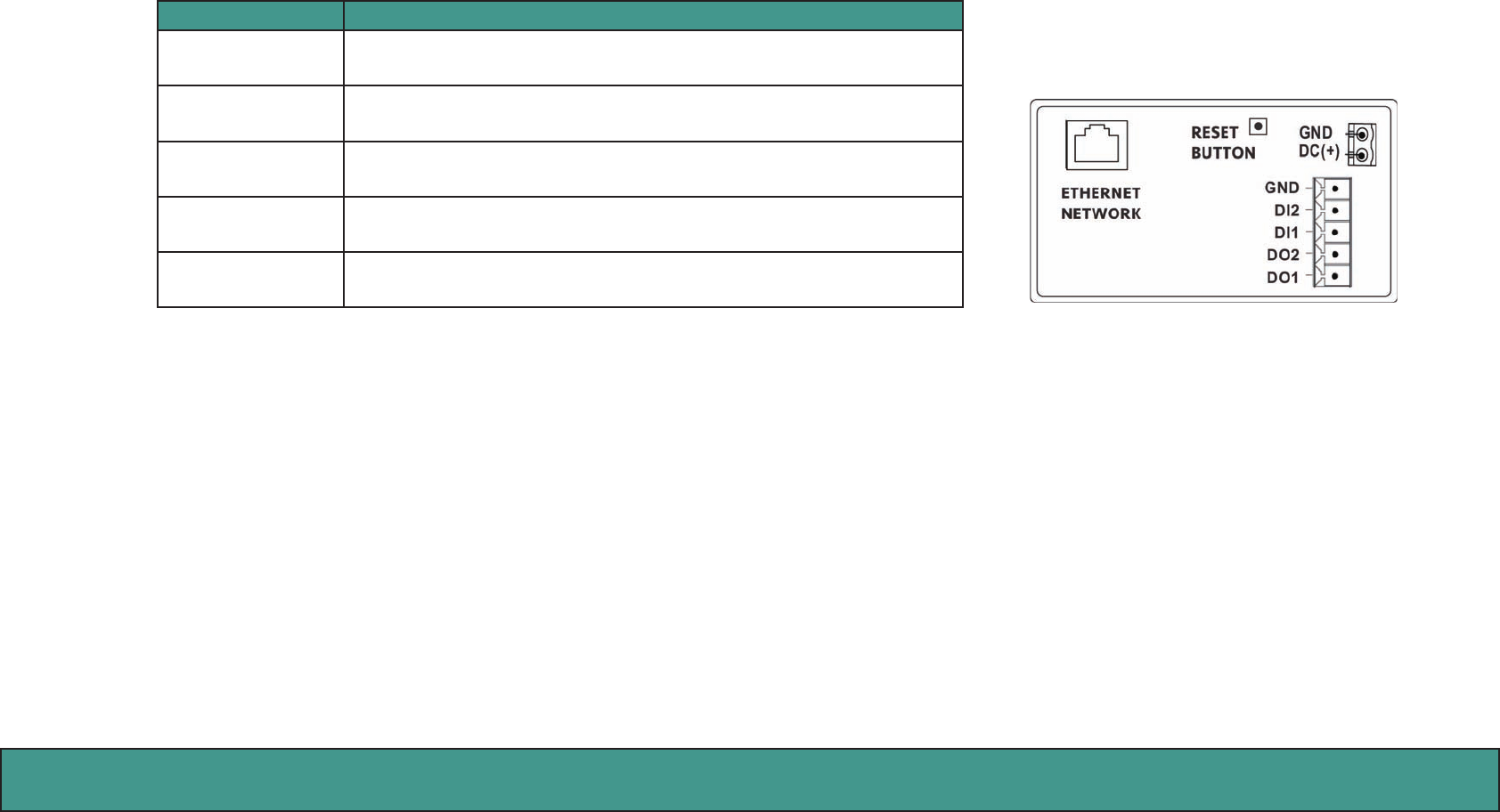
Wire and cable go through wall and corrugated tube, and are used for DC power, network connection, and relay control. There are IO connectors on
the rear side of the DB3100R. They are for DC power, Ethernet port (RJ-45 connector), and GPIO wire. Please refer to the Figure and following sec-
tion- GPIO & Relay Control. For space saving, AR Relay Board can be placed on the top of the rear side and connect GPIO wires.
Figure 11: Wire and Cable Connection on the Rear Side of DB3100R
Amroad Technology Inc.15
MANUAL FOR SYSTEM INTEGRATOR
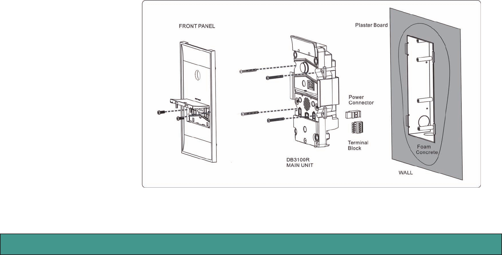
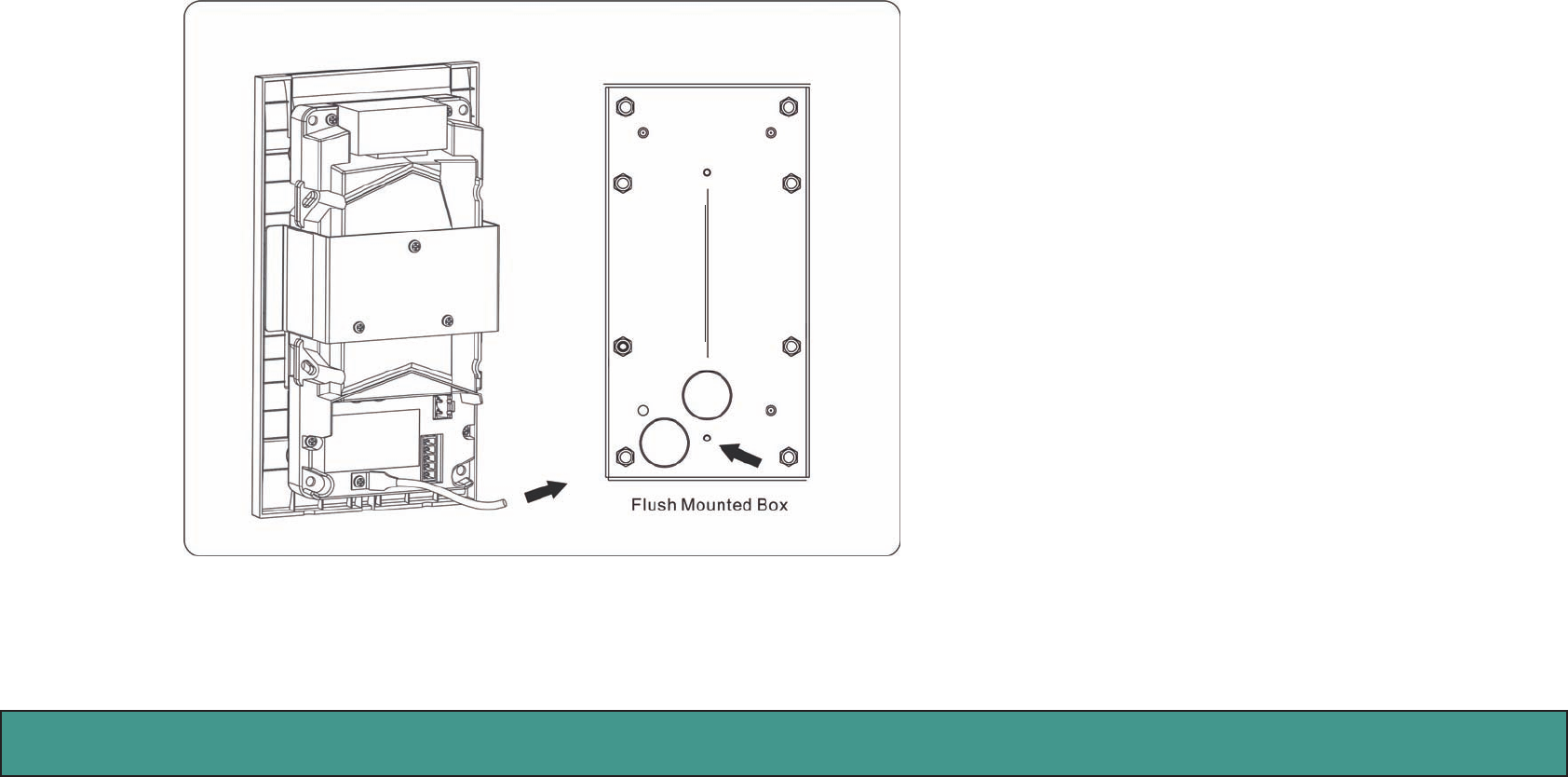
4. Installing DB3100R Unit
Before installing DB3100R on the wall, Flush-Mounted Box should be first mounted on the wall firmly. The following diagram shows the
detail on how to install DB3100R Unit into Flush-Mounted Box.
Secure DB3100R Main Unit
to Flush-Mounted Box
by tightening four long
screws.
Then, attach Front Panel
by putting front cover on
DB3010R Main unit and
firmly press Front Panel to
snap into DB3100R Main
Unit. Lift Doorbell button
and use two short screws
to secure Front Panel.
NOTE:
Before securing DB3100R
Main Unit to Flush-Mount-
ed Box, you should have
connected Ethernet cable,
power wire, relay control
wiring.
Figure 12: The details on how to install DB3100R Unit
Amroad Technology Inc. 16 17
DB3100R VIDEO DOOR PHONE
GPIO (General Purpose Input/Output) & Relay Control
The following table explains input and out put pins of GPIO and Relay Control.
Port denition Description
GND Connect to Ground (GND)
DI2 (Digital Input
port 2)
DI2 is used to connect to PIR (Movement Detector, Intruder Detec-
tor).
DI1 (Digital Input
port 1)
DI1 is used for is used for detecting whether the door is closed or not.
DO2 (Digital Out-
put port 2)
Once DI2 is triggered, DO2 will turn on external light for 30 seconds.
DO1(Digital Out-
put port 1)
Connect to AR Relay Board to control Electronic Door Lock.
Figure 13: IO Connectors on the Rear Side of the DB3100R
Reset Button
There is a reset button on the back of the DB3100R.
The default IP type setting of the Video Door Phone is “DHCP Client “.
A. Pressing the reset button for 3 seconds=>DB3100R will turn into Statics IP mode as “192.168.0.50” and reboot by itself.
B. Or pressing for over 6 seconds =>Turn to DHCP mode as the default value and reboot by itself (Restore to factory setting).
NOTE: For more detailed information on GPIO, please refer to Appendix A. IO Application.
Amroad Technology Inc.17
MANUAL FOR SYSTEM INTEGRATOR
Connecting to Ground Wire
To prevent power surge and lighting strike from damaging DB3100R, Flush-Mounted Box should be connected to the ground wire
(earth wire) of the building. Connect the wire of DB3100R to Flush-Mounted Box as shown in Figure. Remember to tighten the screws
on both sides.
Figure 14: Connecting to Ground Wire
NOTE:
Flush-Mounted Box should be connected to the
ground wire (earth wire) of the building. Power
Switching for DB3100R should also be connected to
the ground wire (earth wire).
To prevent power surge and lighting strike from
damaging DB3100R.

Amroad Technology Inc. 18 19
DB3100R VIDEO DOOR PHONE

Amroad Technology Inc.19
MANUAL FOR SYSTEM INTEGRATOR
Chapter 4 : Use of the Video Door Phone
Making Calls From Video Door Phone
Using the Video Door Phone is quite easy. You will see “Door bell” on the front side.
Press “ Door Bell ” button to make a call.
Answering Calls on IP Video Phone
To answer the call from Video Door Phone on IP Video Phone is the same as a normal call. You may answer with
following ways:
•Pickupthehandset.
•PresstheSPEAKER button.
•Press“Answer” soft-function key.
Open the Door
You may press the “#” key on IP Video phone to open the door with electronic door lock during answering the
call, but should add an extender relay board to connect with Electronic-door-lock. Please refer to Appendix A.
Common Controls
- You may press the “2” or “8” key of the Video phone to adjust the CMOS brightness.
Figure 15: Press Door Bell
Amroad Technology Inc. 20 21
DB3100R VIDEO DOOR PHONE
DB3100R RFID Card Usage
Residents scan RFID card on the scanning zone. DB3100R will verify the database to determine whether to Open door or not.
Issue Master RFID Card First Time
Without any cabling, just scan RFID card on the DB3100R scanning zone when the DB3100R device 1st time on-line. The RFID card will
be seen as Master RFID Card.
NOTE:
1. Before using Master RFID Card, you need to enable Add User Function by Master RFID Card on RFID page of Entrance Setting unit of
WEB UI (User Interface).
2. If you scan another RFID card instead of Master RFID
Card on DB3100R scanning zone for the first time, the
first-time scanned RFID card will become Master RFID
Card.
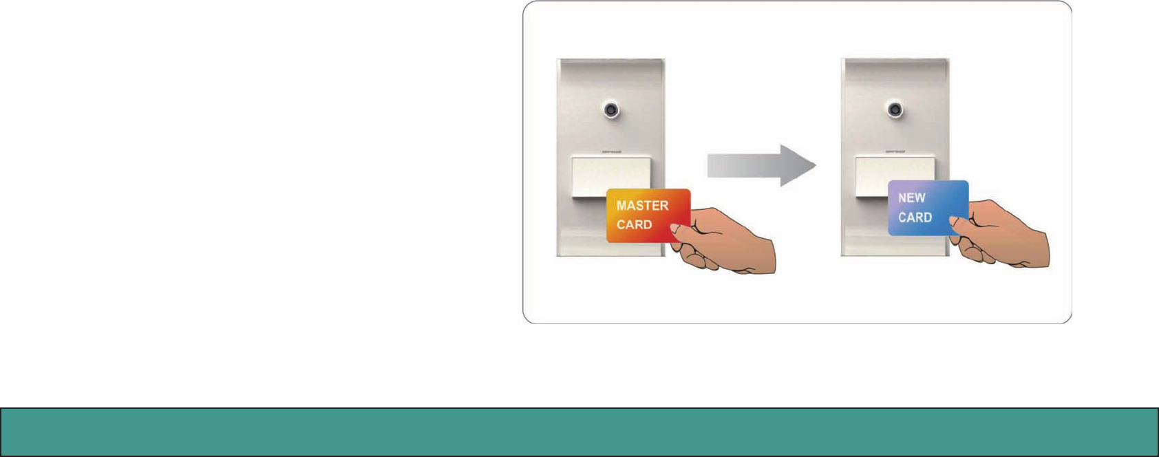
Issue a New Card with Master RFID
Card:
Scan Master RFID Card on DB3100R First.
Within 10 seconds, scan new RFID card on DB3100R,
DB3100R will store new Card number Into Database.
The new RFID card is authorized and can be used to scan
on RFID scanning zone and open door. Figure 16: Scanning RFID Cards
Amroad Technology Inc.21
MANUAL FOR SYSTEM INTEGRATOR
Wall Lamp and RFID LED Indicators
On the top of the DB3100R’s front panel, there are white light LEDs for acting as Wall Lamp. When doorbell is pressed, wall lamp turns
on gradually and projects diuse light. When the conversation is ended, wall lamp turns o slowly.
The 3-color LED indicator is located under the doorbell botton for information and status of scanning RFID card.
LED COLOR STATUS DESCRIPTION
WALL LIGHT WHITE ON When Doorbell is pressed, wall lamp turns on gradually and projects
diuse light…
OFF When the conversation is over, wall lamp turns o slowly…
3-Color LED for
RFID SCANNING
(Front Panel) OFF When RFID module fails…
Solid White ON While RFID Module is ready…
YELLOW/
WHITE
Twinkle
(Green, White) When RFID reader is sensing a RFID card…
GREEN Twinkle Card is accepted and door will be open…
Twinkle for 3 times (0.5sec On, 0.5 sec O…)
RED Twinkle Card is NOT accepted and door will NOT be open…
Twinkle for 3 times (0.5sec On, 0.5 sec O…)
BLUE
Register Master
RFID Card
Scan Master RFID Card for the rst time…
If it is successful, blue light twinkle 3 times (1sec On, 1 sec O…)
Scan Master RFID
Card to issue new
card
Aer scanning Master RFID Card, blue light will light for 10 sec-
onds. (Within 10 seconds, new card should be scanned on RFID
reader.)

Amroad Technology Inc. 22 23
DB3100R VIDEO DOOR PHONE
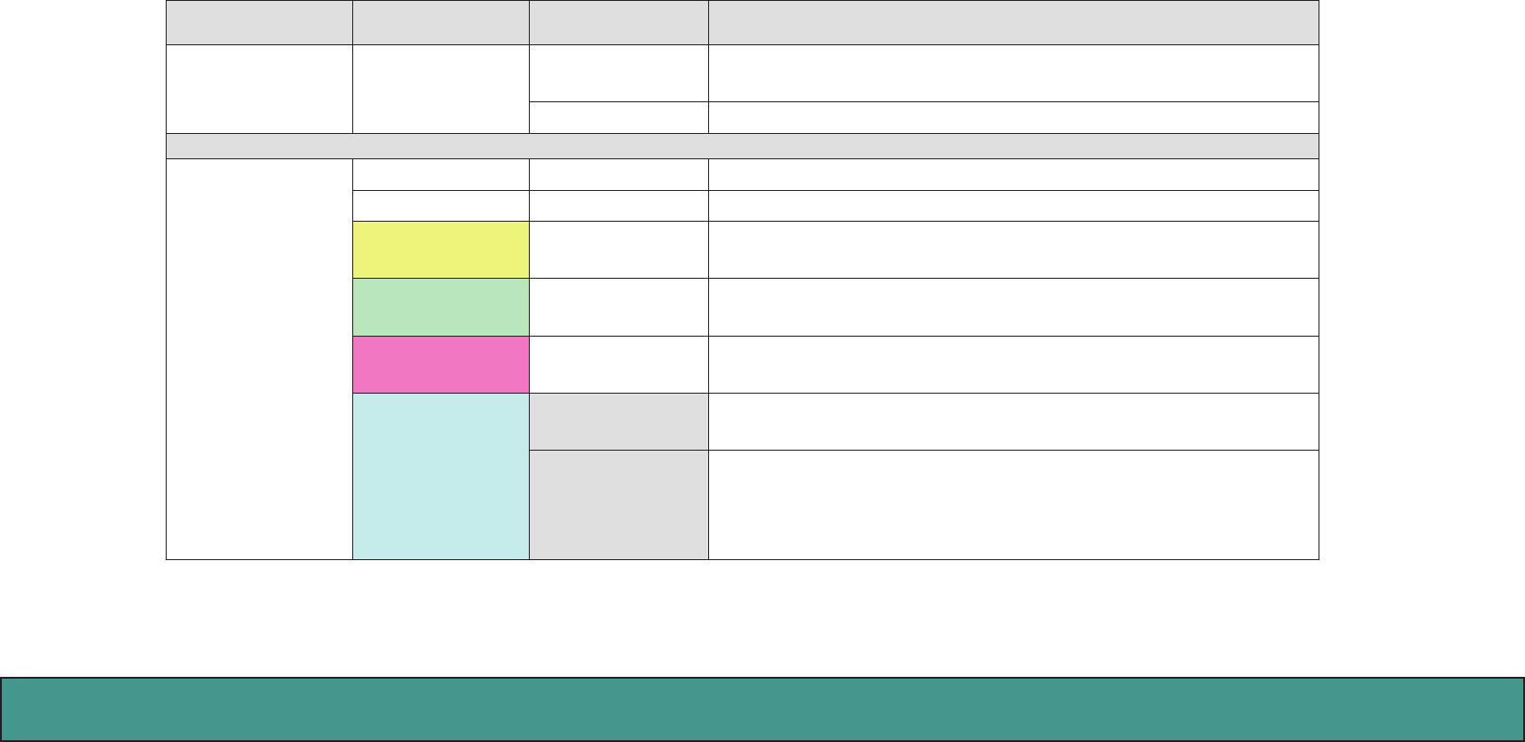
Status LED
There is another 3-color LED Indicator hidden behind the front panel at the bottom-right corner. Once DB3100R is out of order, this
LED helps technical support sta in troubleshooting.
Green LED Red LED Blue LED Description
OFF OFF OFF Normal Condition (SIP Mode)
OFF ON for 1 second OFF Boot is initiated.
Blinking (3-sec On
, One-sec O) OFF OFF Boot procedure 1st stage, OS Initial
OFF ON OFF Boot procedure 2nd stage, AP Ready
Blinking (Green->
Blue->Red)
Blinking (Green->
Blue->Red)
Blinking (Green->
Blue->Red) Firmware Upgrade
OFF OFF On 5 seconds Once Reset! Device becomes Static IP mode.
Blinking 3 times
(0.5-sec On/O) OFF OFF Press RESET button for 6 seconds to restore device to its
factory default setting.
OFF OFF Blinking (3-sec On,
one-sec O) once SIP is NOT registered.
OFF Blinking (3-sec O,
one-sec On) OFF Network is Disconnected.
OFF Blinking (One-sec
On, 3-sec O) OFF Network is connected, but the device fails to obtain IP ad-
dress.
OFF Blinking (One-sec
On, One-sec O) OFF Alarm is triggered.
Amroad Technology Inc.23
MANUAL FOR SYSTEM INTEGRATOR
Audio Announcement
To fit some specific scenarios, DB3100R will automatically play following audio announcement to remind residents.
Audio Announcement Scenario
“Please Scan Your New Card” DB3100R plays this audio announcement after scanning Master RFID
Card on RFID scanning zone and user is ready to issue new card.
“Your New Card has been
Added” DB3100R plays this audio announcement when scanning new card on
RFID scanning zone and new card is registered by DB3100R’s database.
“Fail to Add Your New Card” DB3100R plays this audio announcement when scanning new card
on RFID scanning zone and new card is rejected to be registered by
DB3100R.
“The Door Is Not Closed.” DB3100R will play this audio announcement while resident’s door is not
closed well. (Resident should have installed Electronic Door Lock and
detector- magnetic switch)
“Burglar! Burglar! Watch Out!” DB3100R will play this audio announcement when resident’s DB3100R
Video Door Phone is damaged by intruder. (There is a micro switch hid-
den behind front panel.)

Amroad Technology Inc. 24 25
DB3100R VIDEO DOOR PHONE
Amroad Technology Inc.25
MANUAL FOR SYSTEM INTEGRATOR
Chapter 5 : Configuring Video Door Phone
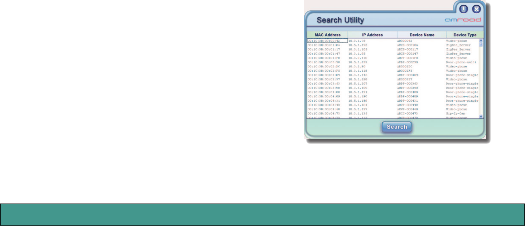
Finding Video Door Phone on Networks
The default connection type setting of the Video Door Phone is “
DHCP Client
”, it is a typical network mode. There is a software utility
provided by your local distributor or local dealer which is able to help you to find your Video Door Phone when using dynamic IP address.
Please execute following utility:
AmRoad Search Tool.exe
You will see a window pop up on screen. This utility will search whole network
segment automatically when utility is activated, then it will show search
results. You may press the “Search” button to search again. The search result
includes following elements:
MAC Address:
This MAC is a unique number that provided by manufacturer.
IP Address:
Here shows the IP address of found Devices (Video Door phone).
Device Name / Device Type:
Here shows which type of devices are found. For
example, you may find Video Door Phone/ IP Video Phone in the same net-
work.
Figure 17: Search Tool - Search Utility
Amroad Technology Inc. 26 27
DB3100R VIDEO DOOR PHONE
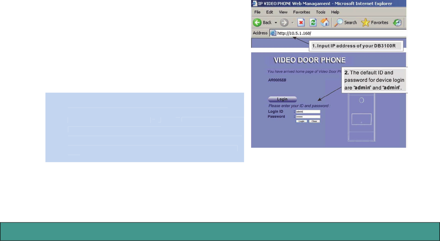
Entering Web User Interface
Input the
IP address
of this product on your browser, then you will see
home page of the Video Door Phone appearing.
Web UI is protected by Login ID and Password. Press the “
Login
” button,
then you will see input fields:
Login ID
and
Password
. Please key in the cor-
rect ID and password, and then press second “
Login
” button to enter Web
UI. The default ID and password are:
Login ID: admin
Password: admin
NOTE: 1. While configuring WEB UI (User Interface), please do not operate
NOTE: 1. While configuring WEB UI (User Interface), please do not operate
this product so as to prevent this product being out of order.
2. Do not input special symbols
“
,
\
, and
&
in the fields on the WEB
in the fields on the WEB
UI. Otherwise, you may fail to save your setting normally.
3. After configuring some Web pages and pressing “SAVE” button,
you need to wait a little longer for system to save the configura-
tion.
Figure 18: System Login
Amroad Technology Inc.27
MANUAL FOR SYSTEM INTEGRATOR
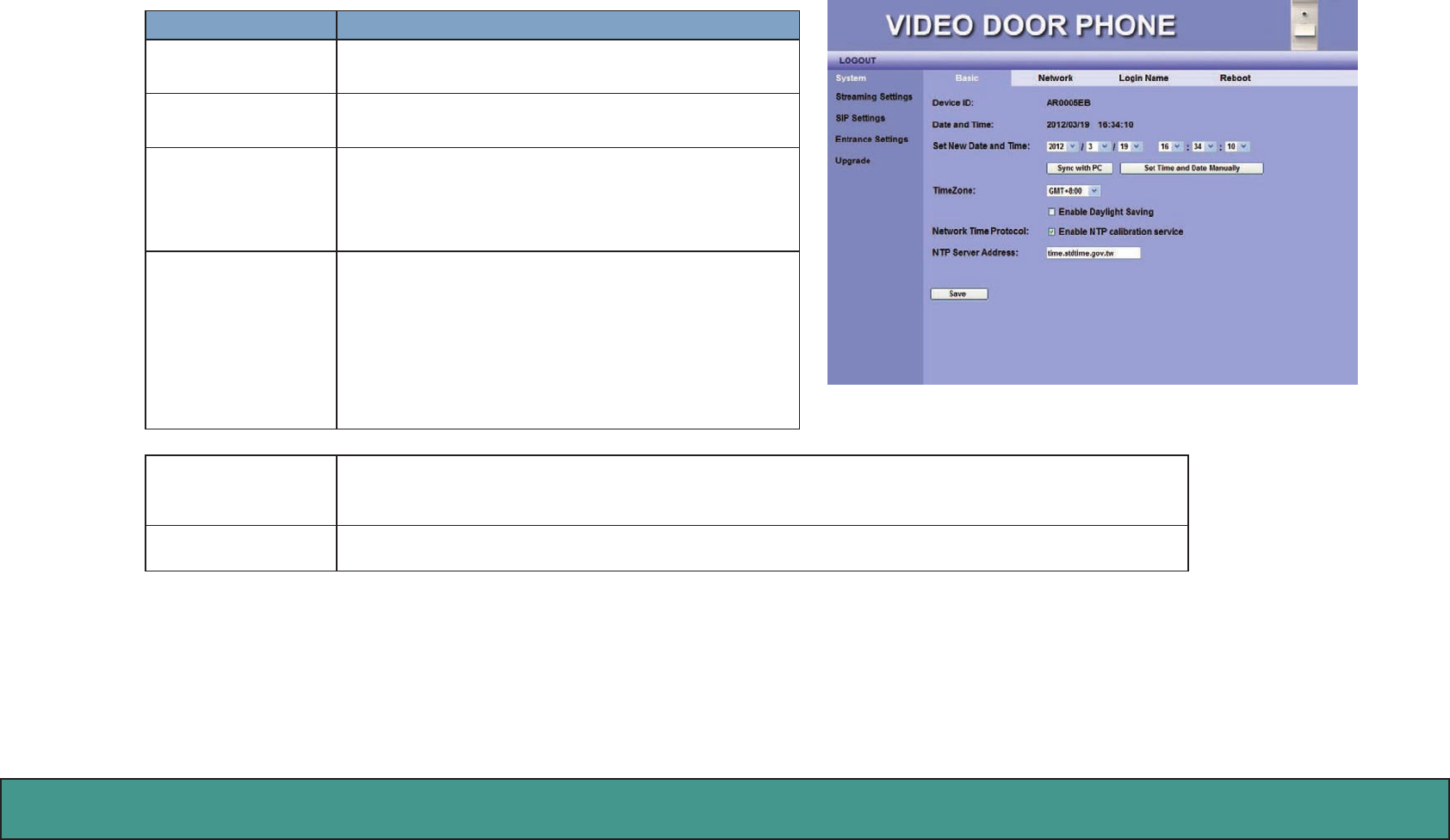
System - Basic Settings
Item Description
Device ID This ID is a unique number that assigned by manu-
facturer.
Date & Time Here shows date and time set on this video door
phone.
Set New Date and
Time
These fields allow user to set correct date and time
according to the local–standard. You may syn-
chronize phone time to match your PC by pressing
“Sync with PC” button.
TimeZone This field allows you to select your time zone to fit
your location. You can enable the Daylight-Saving
feature if needed.
NOTE: Daylight Saving Time is a way of getting
more light out of the day by advancing clocks by
one hour during the summer.
Network Time Pro-
tocol
Enable NTP Calibration service to allow the system to calibrate the time with NTP server
through Internet.
NTP Server Address You may use your preferred NTP server by input new address here.
Figure 19: System - Basic
Amroad Technology Inc. 28 29
DB3100R VIDEO DOOR PHONE
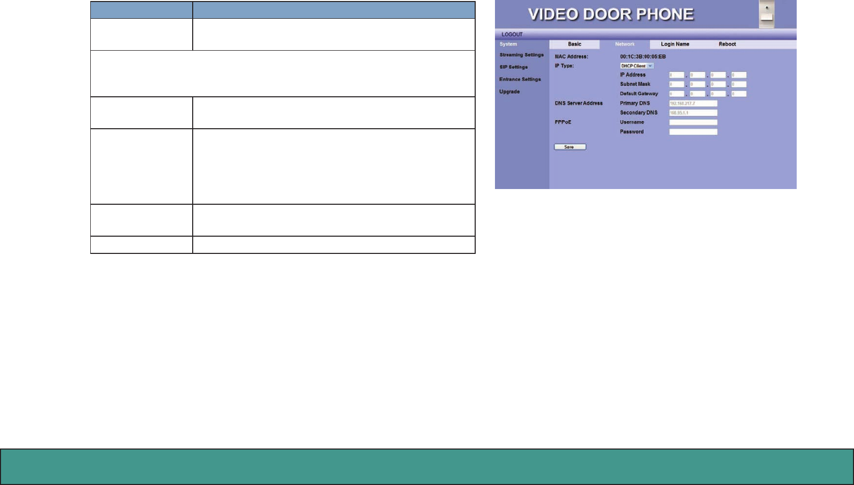
Figure 20: Network
System - Networking Settings
Item Description
MAC Address This is a quasi-unique identifier attached to most
network adapters.
IP Type
The default value is DHCP Client.
There are three options: DHCP Client, Static IP and PPPoE.
A. DHCP Client: The system will automatically assign your Video Door
Phone an IP address.
B. PPPoE: This allows you to set Internet connection with ID
Account and Password.
NOTE: For PPPoE connection mode, we suggest that
bandwidth-128kbps would have better video quality.
C. Static IP: You have to input IP address, Subnet Mask, Default
Gateway, Primary DNS and Secondary DNS data.
Save Click this button to save your setting.
Amroad Technology Inc.29
MANUAL FOR SYSTEM INTEGRATOR
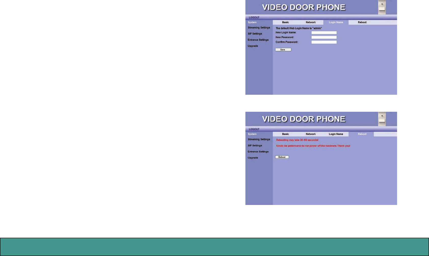
System Login Name
The default ID and password for system login are admin and admin.
User may change his Login ID and Password on the webpage by entering new
Login ID and Password.
System Reboot
When user needs to reboot DB3100R remotely, just click “Reboot” button on
this webpage to start this action. After confirm rebooting, Web User Inter-
face will back to the home page, but the video door phone may take 30~60
seconds to restart its system.
NOTE: DO NOT operate the DB3100R while system is rebooted (reset).
Figure 22: System Reboot
Figure 21: Login Name
Amroad Technology Inc. 30 31
DB3100R VIDEO DOOR PHONE
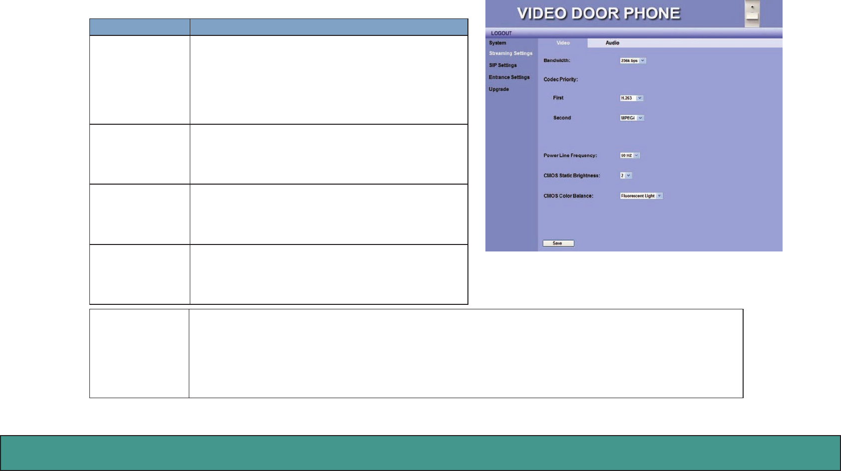
Streaming Settings – Video
You may set change the video settings in this page.
Item Description
Bandwidth You may select preferred bandwidth for video and
audio streaming. There are 4 options: 128Kbps,
256Kbps, 384Kbps, and 512Kbps. Please check which
bandwidth is suitable for you with your service pro-
vider.
Default setting is 256Kbps.
Codec Priority– First – You may select the Video streaming priority -
H.263.
Second –You may select the Video streaming priority
- H.263, or Disable.
Power Line Fre-
quency
You may select the power frequency according to
your local power specifications. Wrong power fre-
quency may cause the video icking abnormally.
Default setting is 60Hz.
CMOS Static
Brightness
This item allows you to adjust the brightness of
CMOS according to the lighting environment of the
installed location. Higher value makes the video
brighter.
CMOS Color Bal-
ance
This item allows you to adjust the color of video. Select according to the lighting environment: Fluorescent
Light, Yellow Lamps and Orange Lamps.
NOTE: Fluorescent Light – This condition is suited for white lighting environment.
Yellow Lamps – This condition is suited for indoor yellow bulb environment.
Orange Lamps – This condition is suited for indoor orange color or more red color environments.
Figure 23: Video Setting
Amroad Technology Inc.31
MANUAL FOR SYSTEM INTEGRATOR
Item Descrition
Save Click this button to save your setting.
NOTE: If DB3100R can’t get the correct value of the CMOS brightness in some environment, please adjust the brightness value
via IP Video phone by pressing “2”(brighter) or “8”(darker) during conversation.
Amroad Technology Inc. 32 33
DB3100R VIDEO DOOR PHONE
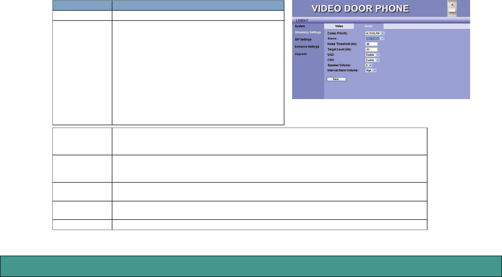
Streaming Settings – Audio
Item Description
Code Priority You may select the Audio streaming priority – G.711.
Scene Select Disable, Enable or User Define.
When “User Define” is selected, the following two
items appears:
Noise Threshold (db): Default: -40. The voice intensity
that is lower than the value (-40db) will be neglected.
(Acceptable value -40~-52)
Target Level (db): Default: -23 The voice intensity
that is around normal intensity will be processed to be
the value (-23db). (Acceptable value -20~-32)
VAD You may enable or disable Voice-Active-Detection function here. The DB3100R will detect back-
ground noise and send silence packet to the other end if this feature is enabled. This allows called
party to hear better audio quality.
CNG You may enable or disable Comfortable-Noise-Generate function here. The DB3100R will generate
background noise when receiving silence packet from the other end if this feature is enabled. This al-
lows called party to hear better audio quality.
Speaker Volume This item allows you to select volume of speaker. There are 10 levels, 0 ~ 9.
Internal Alarm
Volume
Select “High” to turn Internal Alarm Volume Up, or select “Low” to turn Internal Alarm Volume
Down.
Save Click this button to save your setting.
Figure 24: Audio Setting
Amroad Technology Inc.33
MANUAL FOR SYSTEM INTEGRATOR
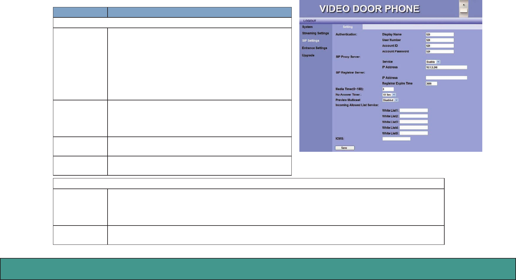
SIP Settings
You may setup advanced SIP service parameters in this page:
Item Description
Authentication
Display Name This name will show on the IP phones of called parties.
You can fill in the preferred name here.
For example, Doorphone
NOTE: Please enter Doorphone in the field of Display
Name. When Door Bell is pressed, there will be “Door-
bell” sound, and enable “Preview Picture” function on
Amroad IP Video Phone/Video Indoor Station.
User Number You may fill in the phone number here, normally it is pro-
vided by service provider. To work with IP PBX, you may
fill in extension number.
For example, 524
Account ID You may fill in your account name of SIP service in this
field. For example, 524
Account Pass-
word
You may fill in the password of your SIP service account.
For example, 524
SIP Proxy Server
Service You may select “Enable” or “Disable” the SIP Proxy Server in the dropdown menu.
NOTE: For Peer-to-Peer mode, both devices (DB3100R and remote device) need to select Disable in the
dropdown menu. And, fill in each other’s IP address.
IP Address You may fill in the IP address of SIP Proxy Server in this field.
NOTE: For Peer-to-Peer mode, user needs to input IP address of the Remote device.
Figure 25: SIP Setting
Amroad Technology Inc. 34 35
DB3100R VIDEO DOOR PHONE
Item Description
SIP Registrar Server
IP Address You may fill in the IP address of SIP Registrar Server here.
Registrar Expire
Time
Set the time for SIP registration authorization
The default is 3600 seconds.
Media Timer
(0~180)
This setting allows your video door phone to force release automatically a conversational call when your
phone doesn’t receive any media packets from the remote side during a period of time.
NOTE: If you want to disable this feature, please fill in “0” sec.
No Answer
Timer
When visitor presses the door bell and no one answer the call, the DB3100R will ring for a time period. You
may select the time period- 15sec, 30sec, 45sec, or 60sec. Default is 15 seconds.
NOTE: The setting should be based on your IP PBX.
Preview Multi-
cast
You can select ”Enable” to enable PREVIEW function to view live image when doorbell is pressed and be-
fore it is answered by Amroad IP Video Phone or Video Indoor Station.
Incoming Al-
lowed List
Service:
White List1~List5
Fill in extension numbers(s) in these fields to allow these resident’s SIP-based devices to monitor through
DB3100R by dialing DB3100R’s extension number.
All other SIP-based devices can call in and monitor if all five fields leave blank.
ICMS Input the IP address of ICMS. This function is customized and it allows DB3100R to send pictures of visitors
to ICMS.
Save Click this button to save your setting.
Amroad Technology Inc.35
MANUAL FOR SYSTEM INTEGRATOR
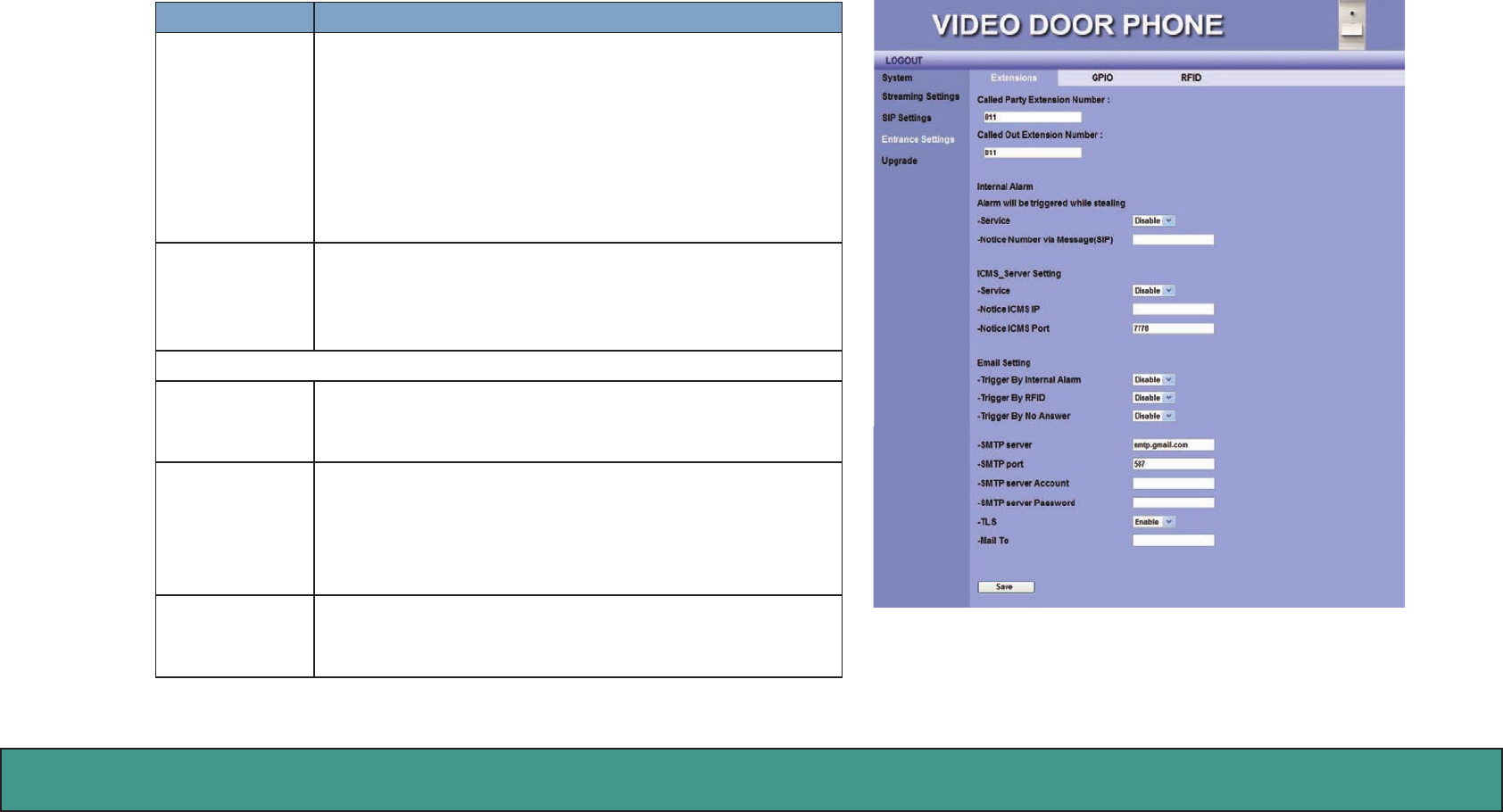
Entrance Settings – Extensions
You may configure call services in this page:
Item Description
Called Party
Extension
Number
Fill in the extension number. When Door Bell button is
pressed, the device will dial to the extension number.
(The extension number or group that is assigned by IP
PBX.)
NOTE: In the Peer-to-Peer mode, you need fill in the
complete extension number and IP address. e.g.
102@10.3.1.128
Called Out Ex-
tension Num-
ber
Fill in the extension number. When ALARM is occurred,
the device will dial to the called party extension number.
(The extension number or group that is assigned by IP
PBX.)
Internal Alarm
Alarm will be
triggered while
stealing
This is a “Burglarproof” function.
Please disable this function when the device is not ready
or during the device is repaired.
Service You can enable or disable the function of “Alarm will be
triggered while stealing”.
Select Disable or Enable for alarm sound when the
alarm is triggered.
Notice Number
via Message
(SIP)
You may fill in the IP Video phone number here. The
device will inform the IP Video Phone when the internal
alarm is triggered.
Figure 26: Entrance Settings

Amroad Technology Inc. 36 37
DB3100R VIDEO DOOR PHONE
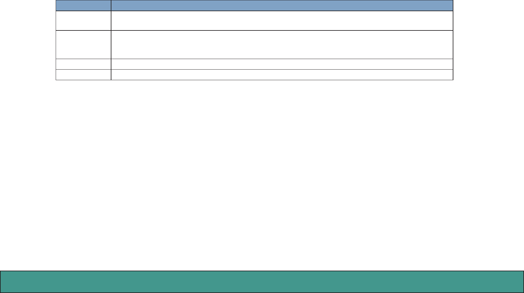
Item Descrition
ICMS_ Server Setting
Amroad ICMS (Intelligent Community Management Server)
Service You can enable or disable the function of ICMS_ Server Setting.
Notice ICMS IP Enter the IP address of ICMS Server.
ICMS will receive the message when Internal Alarm is triggered.
Notice ICMS
Port
Enter the port number of ICMS Server. The default Port Number is 7778.
ICMS will receive the message when Internal Alarm is triggered.
Email Setting
DB3100R will take a picture after sensor is triggered, scanning RFID card, or nobody answering the Video Door Phone
DB3100R. You can disable or enable the following three items for system to send email with picture.
Trigger By In-
ternal Alarm
After internal alarm is triggered, DB3100R will take a picture.
You can enable/disable the function for system to send email with picture.
Trigger By RFID After someone scans RFID card, DB3100R will take a picture.
You can enable/disable the function for system to send email with picture.
Trigger By No
Answer
Nobody answers the DB3100R for a specific time period, DB3100R will take a picture.
You can enable/disable the function for system to send email with picture.
System sending Email needs the related SMTP setting. SMTP is a relatively simple, text-based protocol. Input the valid ac-
count number and password for the SMTP.
SMTP server Host name or IP address of the SMTP server for notification. e.g. smtp.gmail.com
SMTP port To specify the port of the SMTP server. If the field is empty, the default value is 25. The “smtp.gmail.com”
port is 587.
SMTP server
Account
Input SMTP server Account.
NOTE: Just enter the local-part of the email address (ex, John123), and you don’t need to enter the domain
name (ex, @gmail.com)
Amroad Technology Inc.37
MANUAL FOR SYSTEM INTEGRATOR
Item Descrition
SMTP server
Password
Input SMTP server Password.
TLS Set enable/disable for mail transmission that “Confirms Client to the Server identity” action is needed or
not. TLS (Transport Layer Security) is a network protocol that ensures privacy between email servers on
communicating applications.
Mail To Input e-mail address which you want to send to.
Save Click this button to save your setting.
Amroad Technology Inc. 38 39
DB3100R VIDEO DOOR PHONE
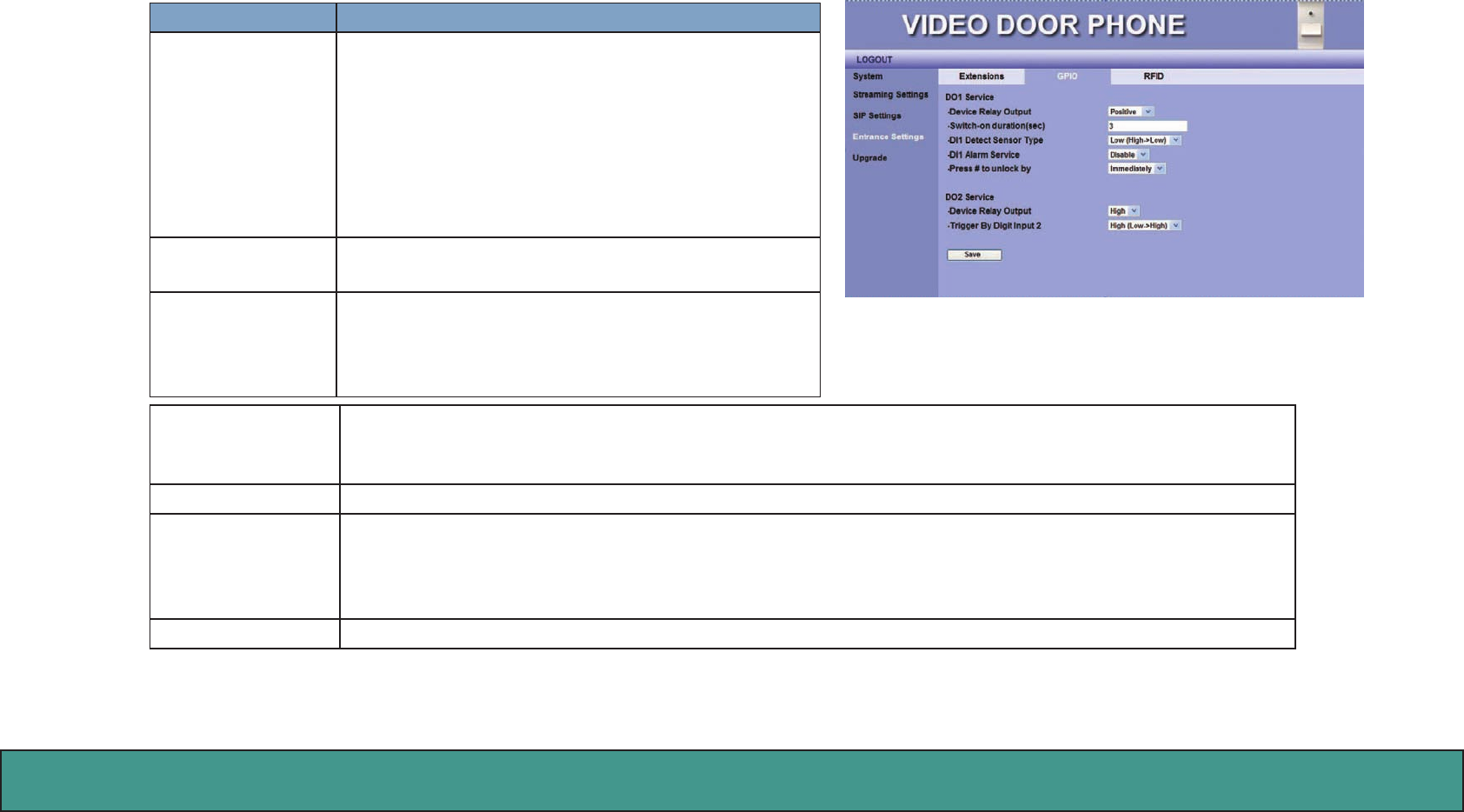
Entrance Settings – GPIO
You may configure GPIO in this page:
Item Descrition
DO1 Service DO1 Service is used to connect with AR Relay Board
to control“Electronic Door Lock”.
The function can be triggered by the following ways.
A. Using Registered RFID Card
B. During conversation, you may press “#” keypad to
open door.
Device Relay Out-
put
You can select Positive/Negative to connect to Posi-
tive/Negative- triggered Electronic Door Lock.
Switch-on duration
(sec)
This item lets you set the time (seconds) for DO1 (Re-
lay Board) to open “Electronic Door Lock”. After the
time period, Relay Board will close “Electronic Door
Lock”. The default is 3 seconds.
DI1 Detect Sensor
Type
There are two options: “High->Low”, and “Low->High”.
You can select the voltage polar of digital input “High->Low” or “Low->High” for triggering.
DI1 Alarm Service Select “Disable”/”Enable” to turn O/On DI1 Alarm when DI1 detects that the door is not closed well.
Press “#” to unlock
by
You can select the timer “Immediately”, ”One Second”, or ”Two Second”.
Press the “#” key from IP Video Phone/Video Indoor Station to open “Electronic Door Lock” during answer-
ing the call.
DO2 Service Once DI2 is triggered, DO2 will turn on external light for 30 seconds.
Figure 27: GPIO Setting
Amroad Technology Inc.39
MANUAL FOR SYSTEM INTEGRATOR
Item Descrition
Device Relay Out-
put
You may select the voltage polar “High” or “Low” for triggering.
Trigger By Digit
Input 2
The Digit Input 2 (DI2) is a trigger point for DO2 Service.
It depends on the voltage polar “High (Low->High)” or “Low (High->Low)”.
NOTE: DI2 is used to connect to PIR (Movement Detector, Intruder Detector).
Save Click this button to save your setting.
NOTE: Be careful with the wires connection of GPIO, especially the default polar voltage of hardware (digit output pins) is high.
Please select and set the related Electronic circuit to meet the hardware initial voltage.
Amroad Technology Inc. 40 41
DB3100R VIDEO DOOR PHONE
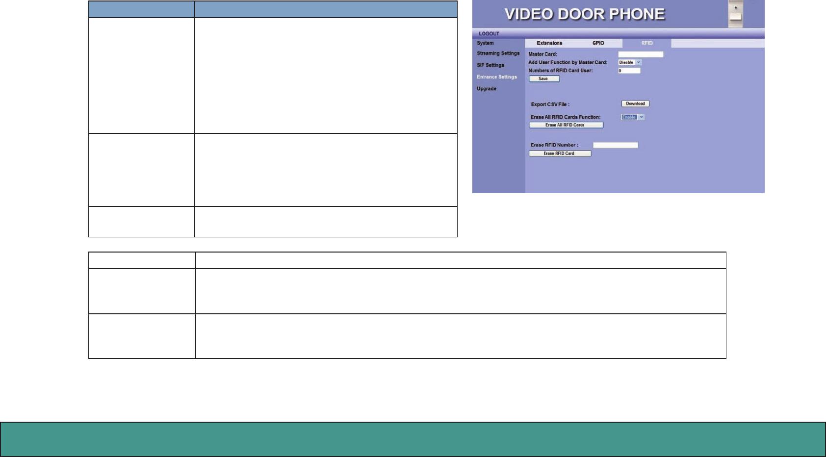
Entrance Settings –RFID
You can get the related RFID information and delete the issued RFID Cards here.
Item Descrition
Master Card This field will display the card number of the Mas-
ter Card. By default, this field is null.
This master card can issue new cards for the new
tenants.
By factory default, this field is null, you can scan a
new RFID Card, and it can be set as Master Card.
Adds User Function
by Master Card
This item is to select Enable/Disable the master
card for issuing new cards.
NOTE: If “Disable” is selected, user is unable to is-
sue new card.
Numbers of RFID
Card User
This field displays the number of RFID cards that
are issued currently.
Save Click this button to save your setting.
Export CSV File Click Download button to export CSV file to open or save the file Card_No.csv on your computer. All is-
sued RFID cards from this Video Door Phone will be listed in the CSV file.
Erase ALL RFID
Cards Func-
tion
This item is used to delete all RFID Card numbers.
When “Enable” is selected, it allows user to erase all RFID card numbers or specific RFID card number.
Press Erase ALL RFID Cards to delete all RFID Card numbers.
Figure 28: RFID Setting
Amroad Technology Inc.41
MANUAL FOR SYSTEM INTEGRATOR
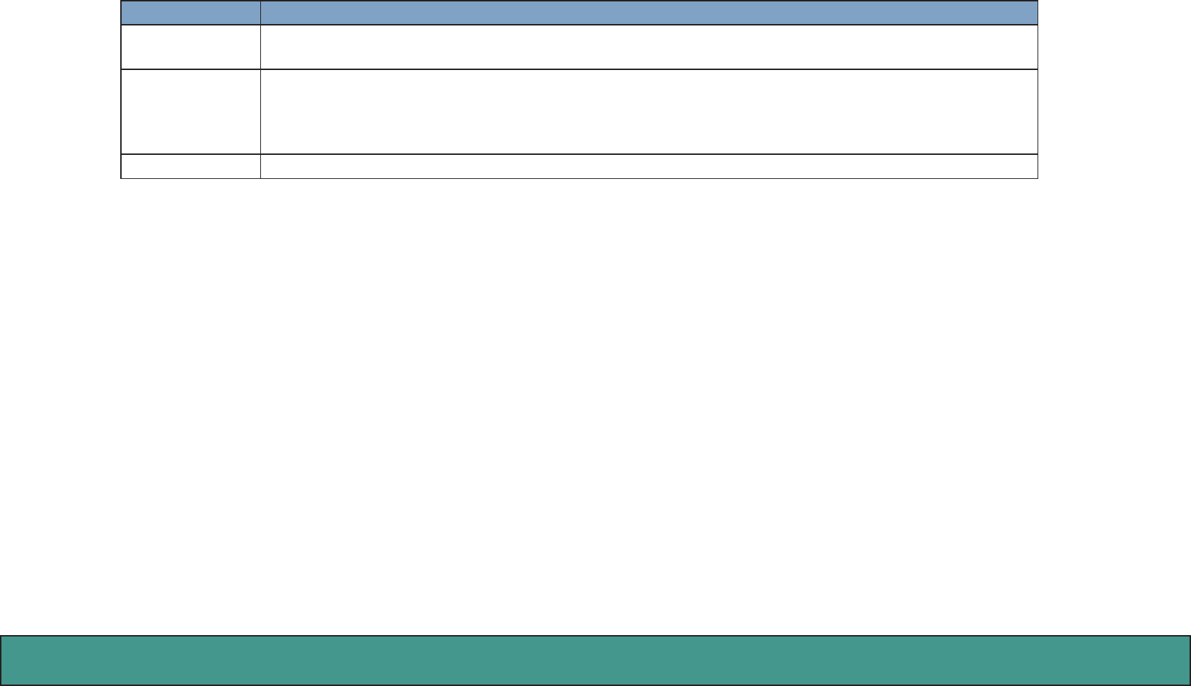
Item Descrition
Erase RFID Number You can input the specific issued RFID card number in the field and press Erase RFID Card to
delete it.
Amroad Technology Inc. 42 43
DB3100R VIDEO DOOR PHONE
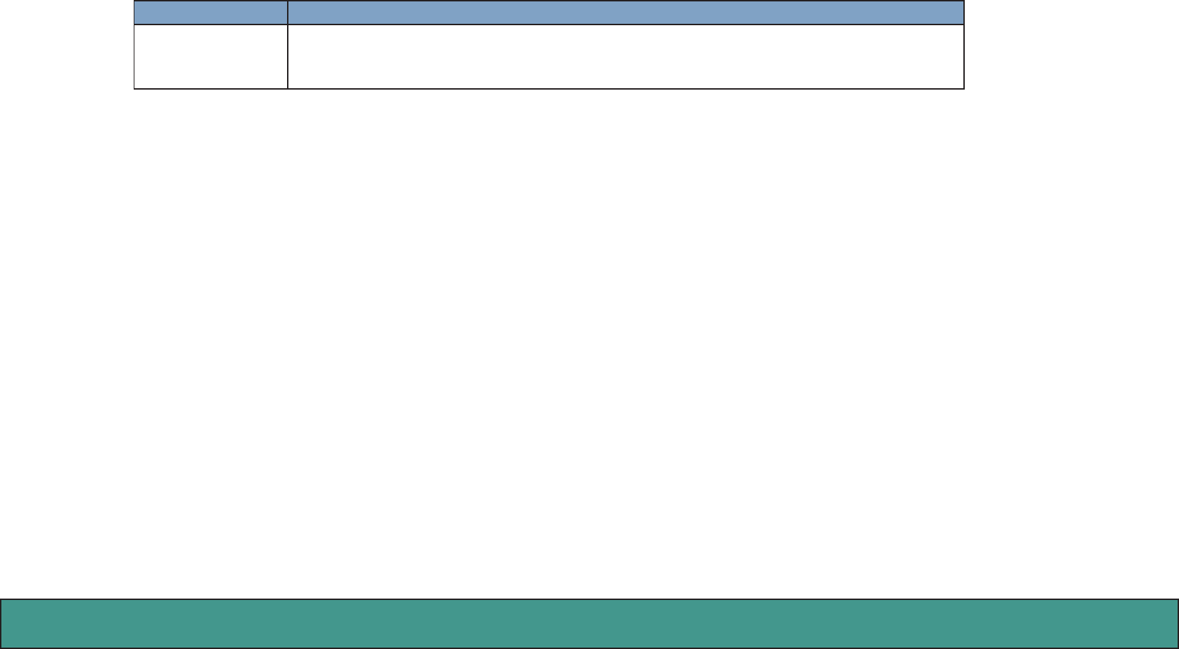
Upgrade –Upgrade
This section allows you to upgrade firmware of DB3100R through network.
Item Descrition
Hardware Version This field shows hardware version number.
Software Version This field shows current firmware version number.
Language This field shows the language of speech announ-
ment.
Select Application
Pack
Press “Browse” button and select Application Pack
from your local disk.
NOTE: Application Pack and Software File should be
uploaded at the same time.
Select Software file You may press Browser button to pop up a File di-
alog box to select the location of the new firmware
that you wish to upgrade.
Upgrade After select the new firmware, you can press Up-
grade button to start the upgrading. You will see
progress bar showing the upgrade status.
WARNING: DO NOT turn o or disconnect the Eth-
ernet cable during upgrade, for it may cause serious
damage to this device.
RFID Module Ver-
sion
This field shows RFID Module version.
Restore Factory
Default
Press the Restore Default button and wait for system to restore its original factory default setting.
Figure 29: Upgrade
Amroad Technology Inc.43
MANUAL FOR SYSTEM INTEGRATOR
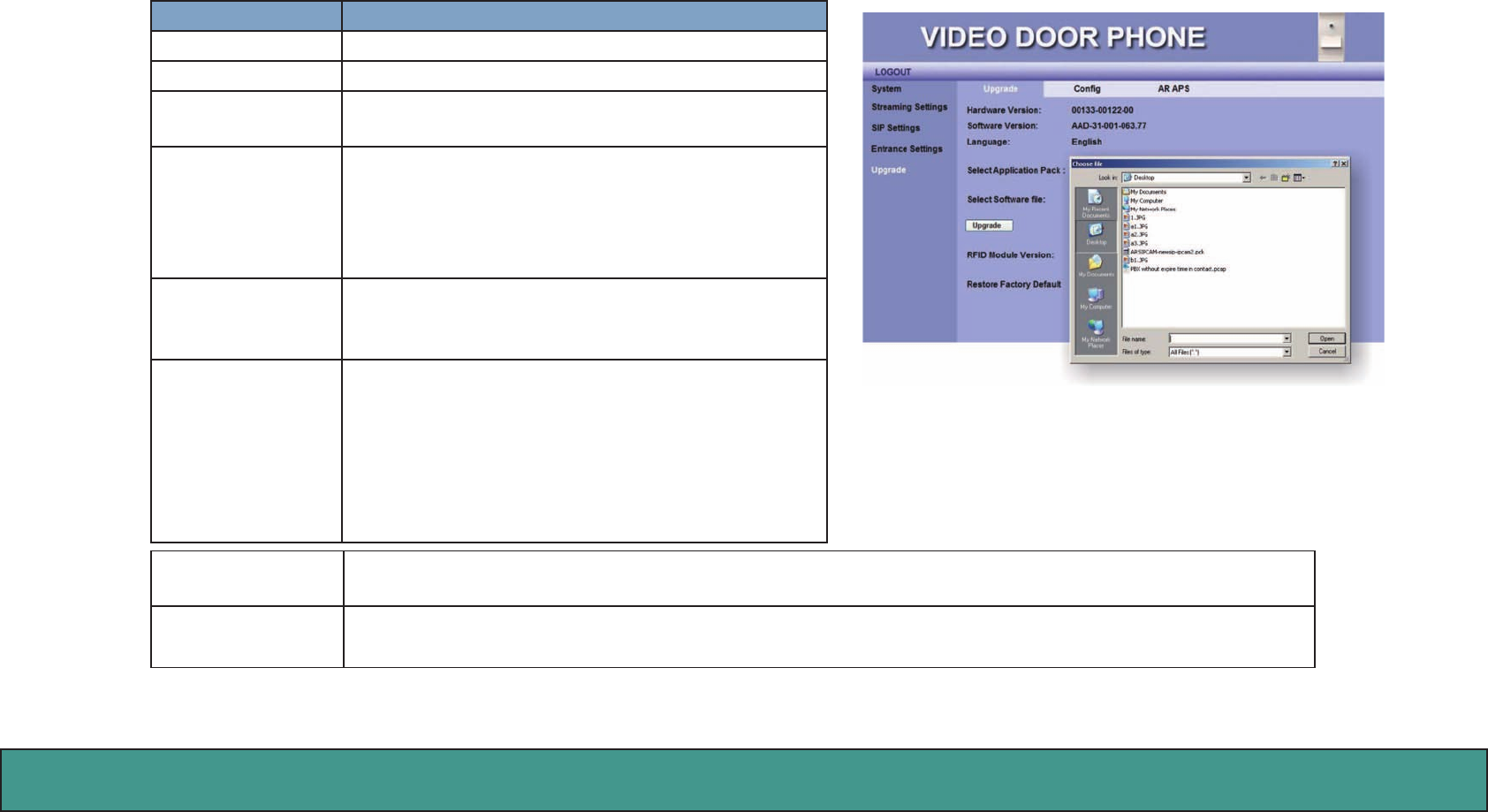
Upgrade –Configuration
Item Descrition
Import File User may press Browse button to select the loca-
tion of the configuration file to import, which you
may previously save to a local directory through the
Export File option.
Upload After selecting the configuration file, you can press
Upload button to start the importing.
Export File You can also use Export File to back up DB3100R
settings on your computer.
Download Press Download button to export, and you are
prompted to click “Open” or “Save” for NewCon-
figuration.xml.
Figure 30: Upgrade- Conguration
Amroad Technology Inc. 44 45
DB3100R VIDEO DOOR PHONE
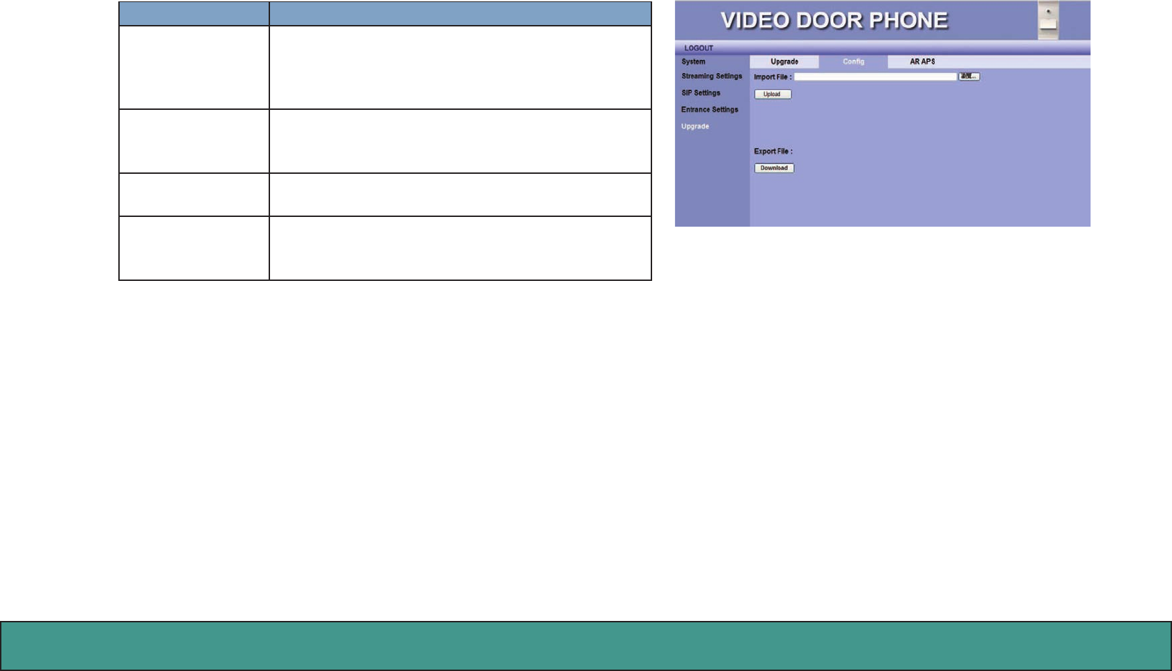
AR APS
Adminstrator can perform system management function through this AR APS (Auto Provision Server) webpage.
Item Descrition
APS_Server This allows adminstrator perform system management
through the following URL.
APS_Server: https://rc.amroad.com.tw/aps/TaServlet/
doorphone.php
Save Click this button to save your setting.
Figure 31: AR APS
Amroad Technology Inc.45
MANUAL FOR SYSTEM INTEGRATOR
Functions Performed by the IP-PBX (Compatible with Amroad
IP-PBX)
Simultaneous Ring –The Distribution Policy is set to Ring All. e.g. When a visitor
calls the group call (say extension 500), group members (say extensions 155, 157,
and 166) will all ring simultaneously.
Call Forwarding – Enter a number to which incoming calls are forwarded when
unanswered. The number could be an extension or a PSTN number with appropri-
ate outbound prefix.
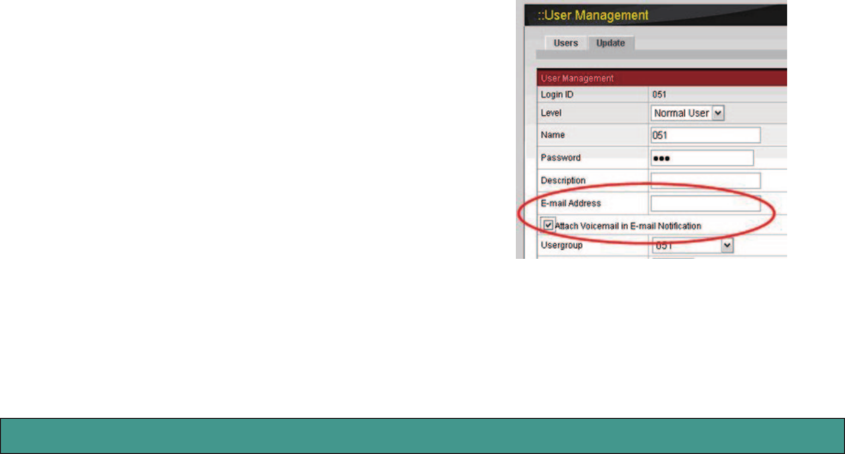
E-Mail/Voicemail Notification – IP PBX has a built-in voice mail subsystem with
a sophisticated IVR menu. A call to an extension unanswered could be configured
to enter voice mail recording procedure. After leaving a message, a notification
e-mail will be sent to the user owns the extension with or without the message in
the form of an attached WAV file.

Amroad Technology Inc. 46 47
DB3100R VIDEO DOOR PHONE
Amroad Technology Inc.47
MANUAL FOR SYSTEM INTEGRATOR
Appendix A : IO Application
Electronic Lock
The DB3100R can connect with various Electronic locks, including Electronic Strikes, Electronic Bolts and Electromagnetic locks.
Wiring Connection and Web Page Setup
There are two types of Electronic door lock applications as below.
One is Electronic Bolt, and the other is Electronic Strike. For more
Electronic locks, please follow the similar method for connection.
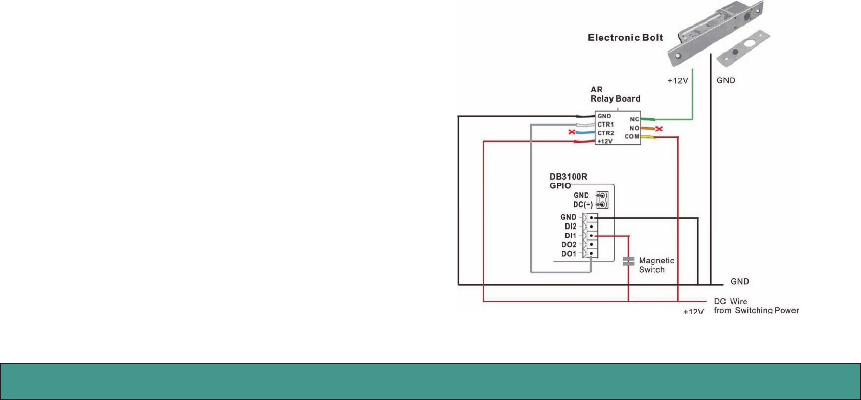
Electronic Bolt
Electronic Bolt
•TheElectronicBoltisclosed
when +12 V is supplied.
•TheElectronicBoltisopened
when +12V is not supplied.
This function can let you press the pound ( # ) key on IP Video
Phone/Video Indoor Station to open the door during answering the
doorbell.
Amroad Technology Inc. 48 49
DB3100R VIDEO DOOR PHONE
DI1 (Trigger Default) : High (Low->High) DI1 is used for is used for detecting whether the door is closed or not.
DO2 (Trigger Default) : High ->Low Once DI2 is triggered, DO2 will turn on external light for 30 seconds.
DI2 (Trigger Default) : High (Low->High) DI2 is used to connect to PIR (Movement Detector, Intruder Detector).
NOTE: MS (Magnetic Switch) is used to detect whether the door is closed or not.
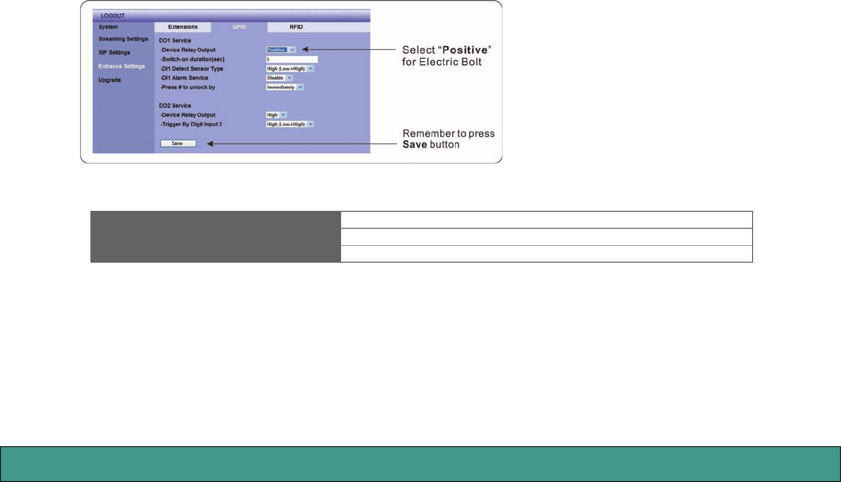
When the wire connection is completed, we need
to select the “Positive” for Electronic Bolt on the
GPIO page of Entrance Setting on DB3100R WEB
User Interface.
Amroad Technology Inc.49
MANUAL FOR SYSTEM INTEGRATOR
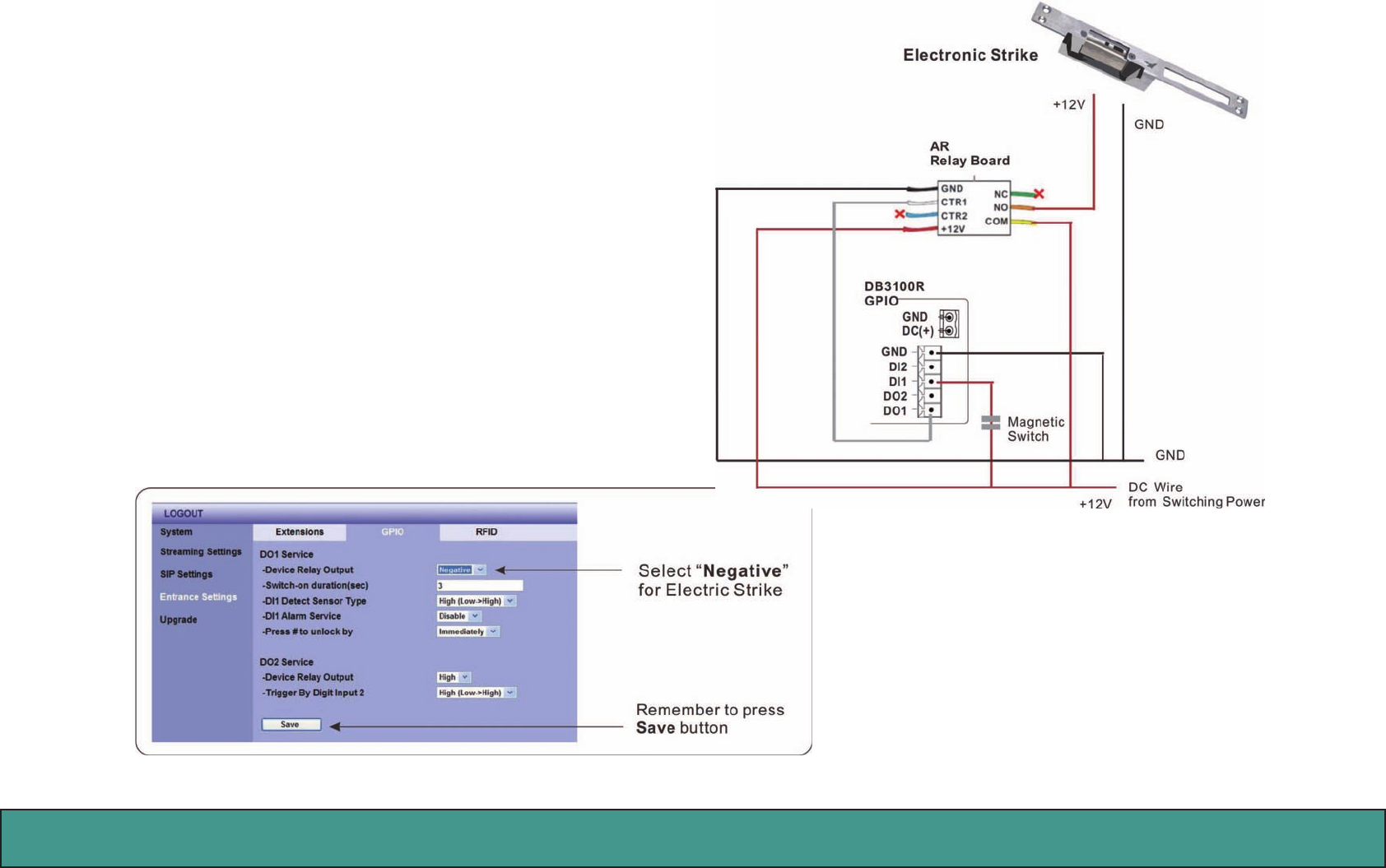
Electronic Strike
Electronic Strike
•TheElectronicStrikeisopened
when +12 V is supplied.
•TheElectronicStrikeisclosed
when +12V is not supplied.
This function can let you press the pound ( # ) key on IP Video
Phone/Video Indoor Station to open the door during answering
the doorbell.
When the wire connection is completed, we need to
select the “Negative” for Electronic Strike on the GPIO
page of Entrance Setting on DB3100R WEB User Inter-
face.

Amroad Technology Inc. 50 51
DB3100R VIDEO DOOR PHONE

Amroad Technology Inc. 52 53
DB3100R VIDEO DOOR PHONE
CE DECLARATION OF CONFORMITY (EUROPE)
Manufacturer declares that this product conforms to the specifications listed below, following the provisions of the European
R&TTE directive 1999/5/EC:
• EN 301 489-1, 301 489-17 General EMC requirements for Radio equipment
• EN 609 50 Safety
• EN 300-328-1, EN 300-328-2 Technical requirements for Radio equipment
Caution: This equipment is intended to be used in all EU and EFTA countries. Outdoor use may be restricted to certain frequencies
and/or may require a license for operation. Contact local Authority for procedure to follow.
Note: Combinations of power levels and antennas resulting in a radiated power level of above 100 mW equivalent isotropic radiated
power (EIRP) are considered as not compliant with the above mentioned directive and are not allowed for use within the European
community and countries that have adopted the European R&TTE directive 1999/5/EC.

Amroad Technology Inc.53
MANUAL FOR SYSTEM INTEGRATOR