AmRoad Technology DP100-25 Video Door Phone User Manual DP100 25 SI Manual 2012 0807
AmRoad Technology Inc. Video Door Phone DP100 25 SI Manual 2012 0807
UserManual.wiki
>
AmRoad Technology
>
DP100 25 User Manual
Users Manual
Navigation menu
Upload a User Manual
Namespaces
Wiki Guide
HTML
PDF
Info
Views
User Manual
Discussion / Help
Navigation
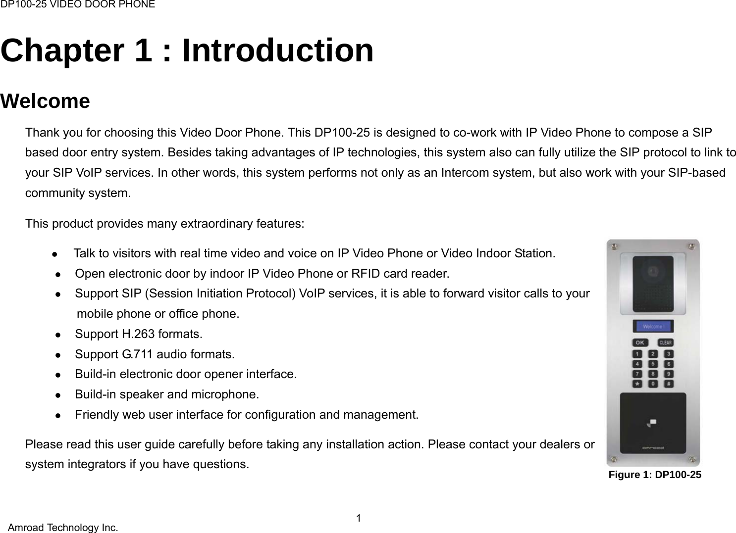
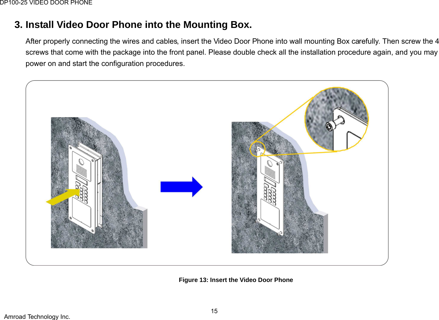
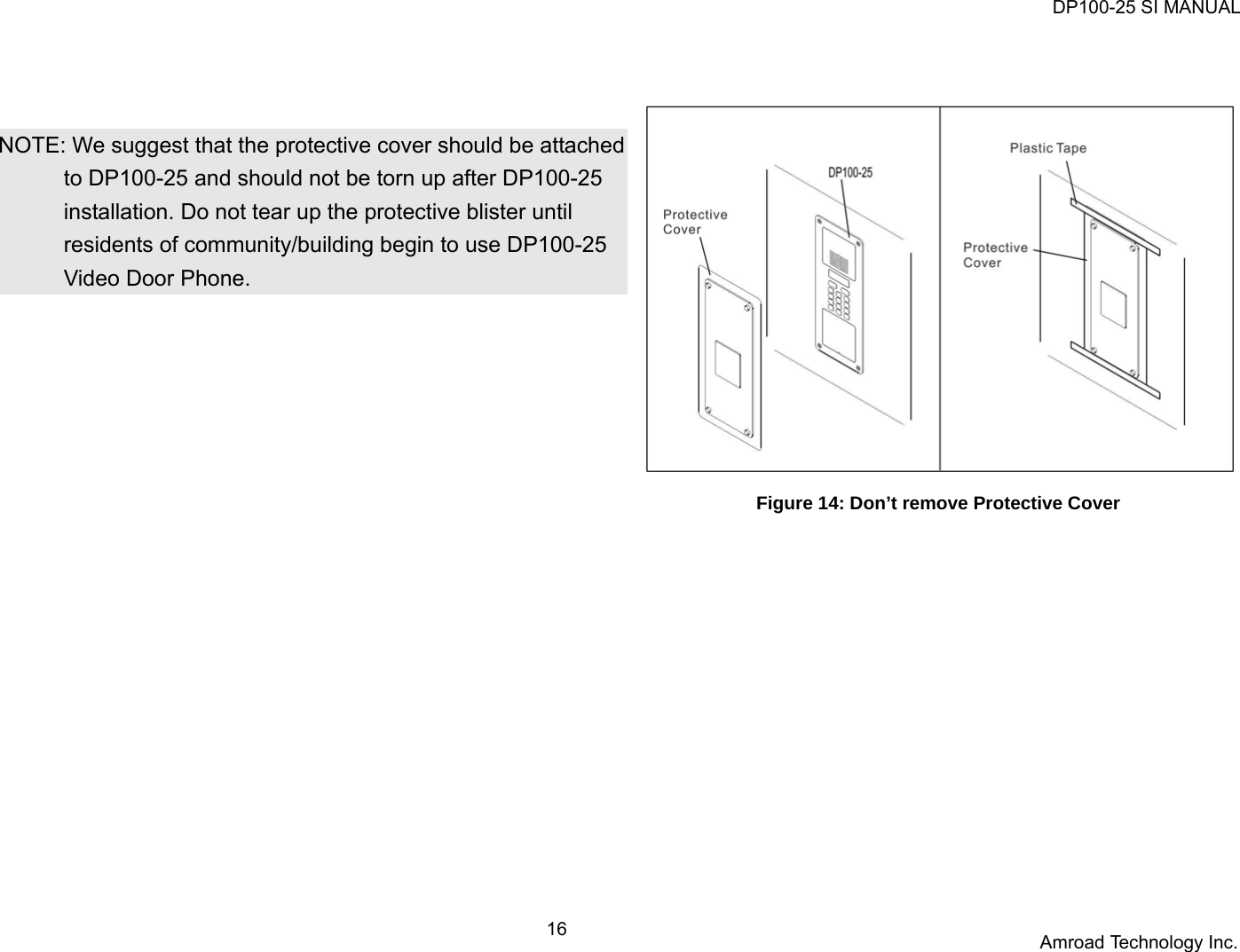
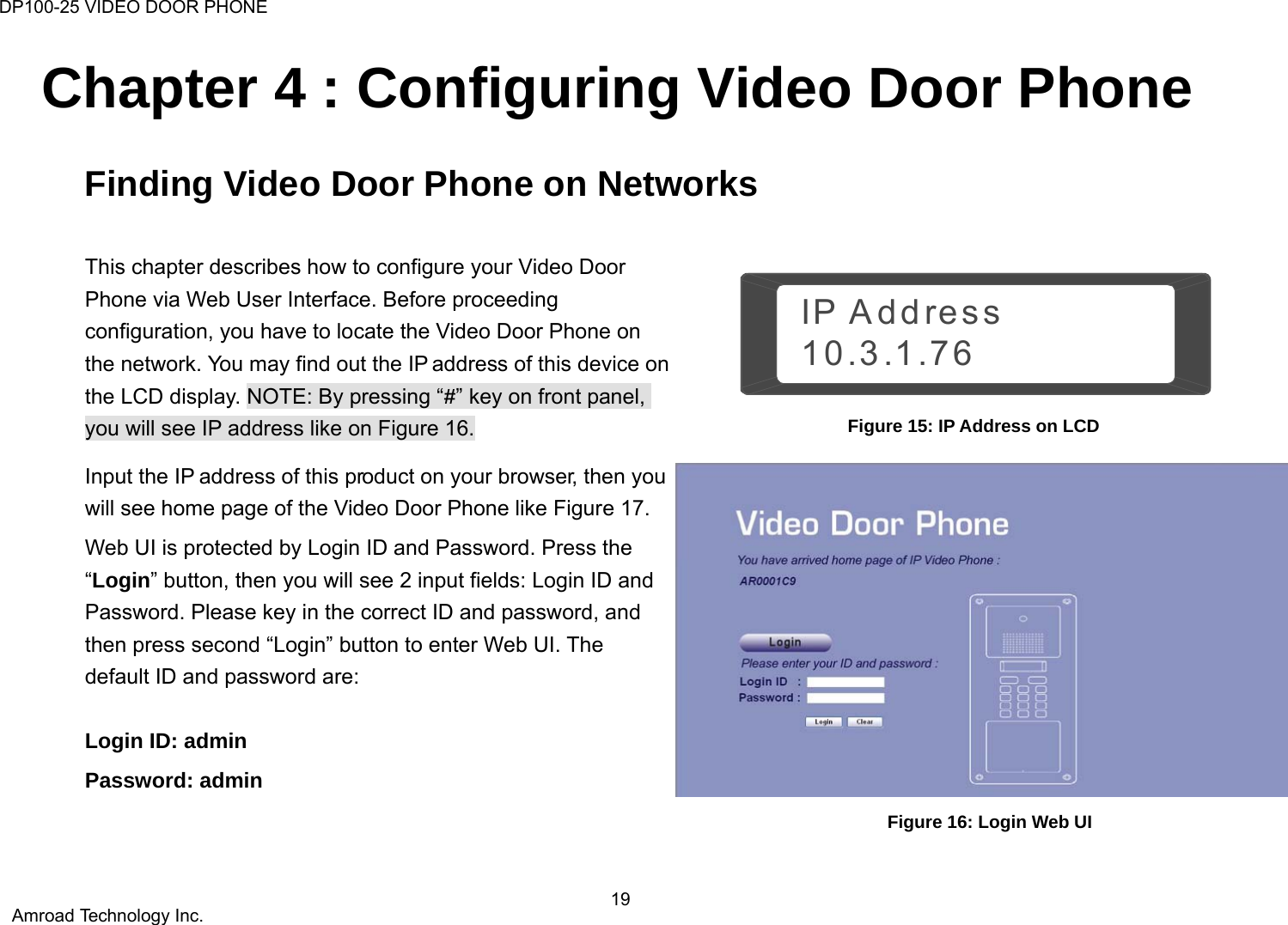
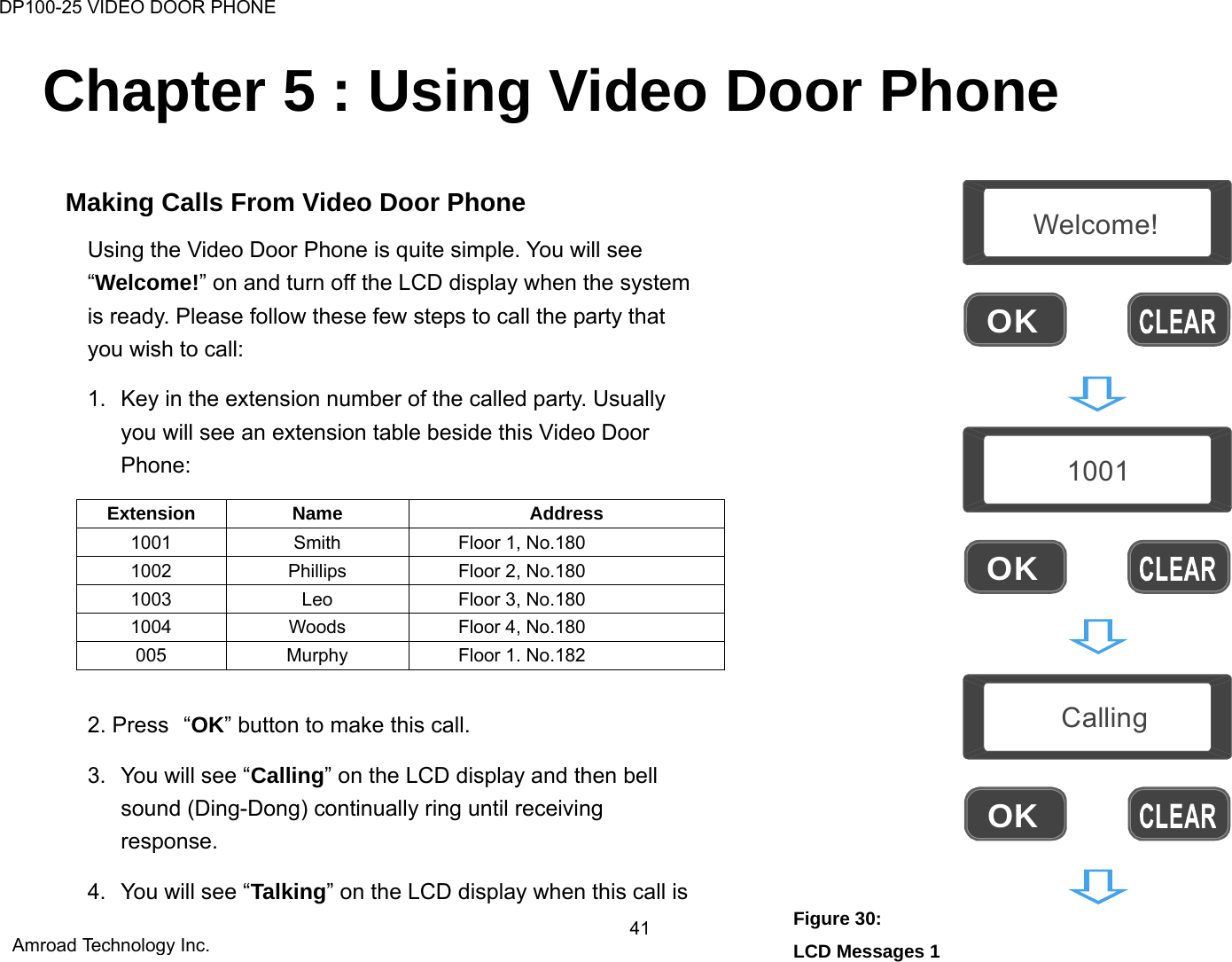
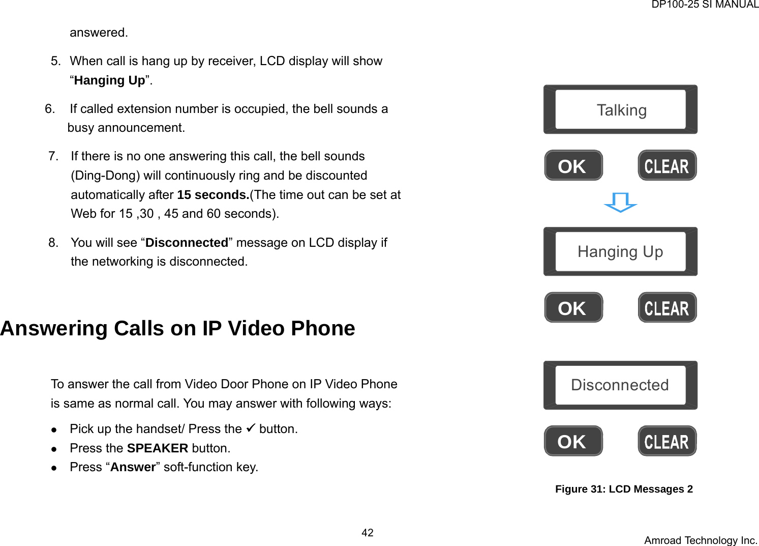
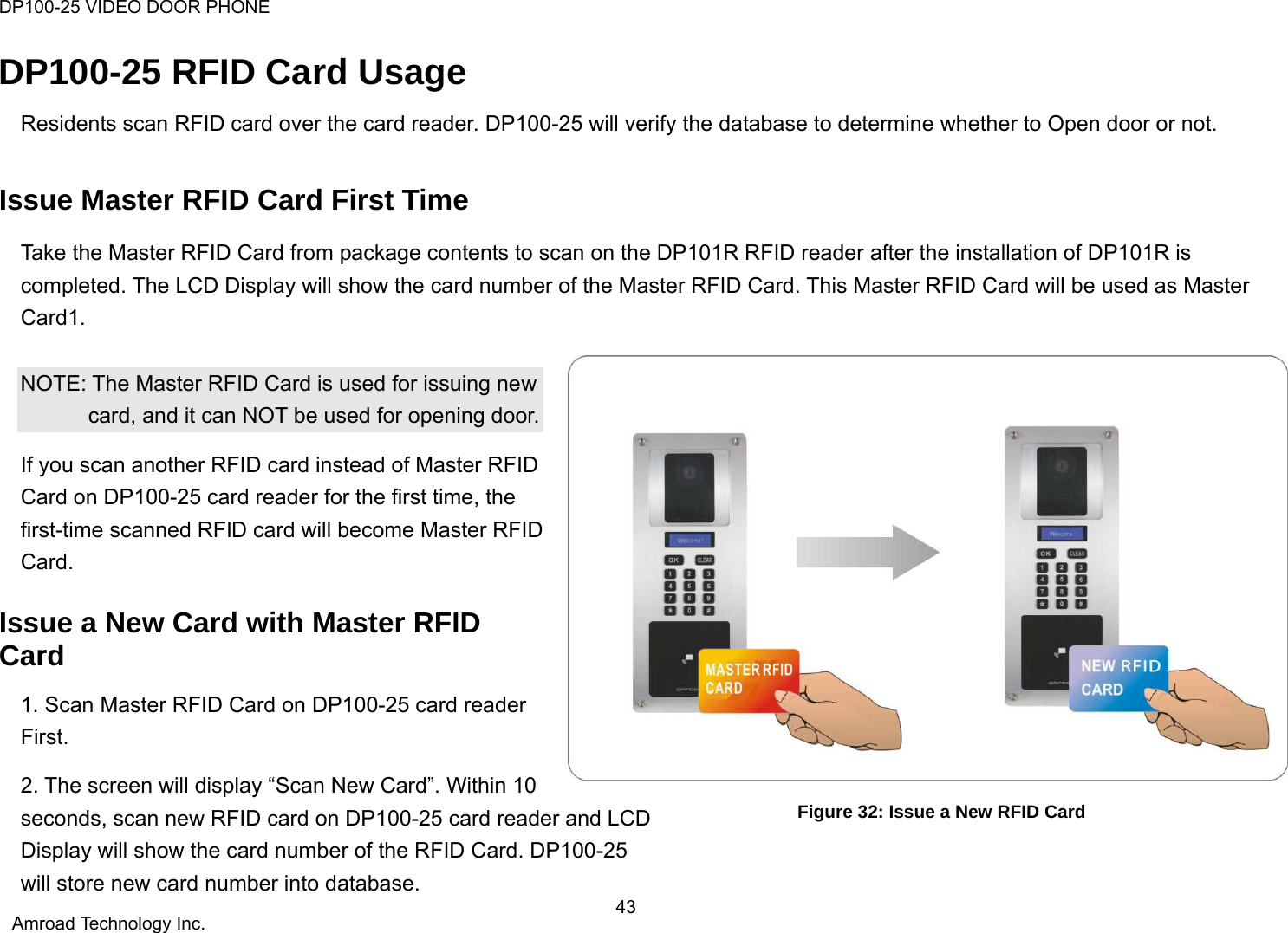
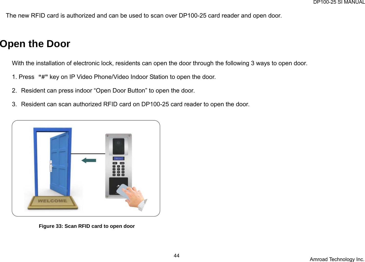
![DP100-25 VIDEO DOOR PHONE 5 Amroad Technology Inc. Chapter 2 : Knowing Video Door Phone Package Contents The following items are included in your Video Door Phone package. Check this list before installation to ensure that you have received all items. n Video Door Phone Unit o Wall Mounting Box p Terminal Connectors q Screw Pack (4 pieces of M6 x 20mm) \ Wrench ] Screw for Earth Wire ^ Wall mounted screw pack _ H-type Terminal Connector for Power Wire ` Cord End Terminal (12 pieces) a Plastic Protective Cover Master RFID Card Quick Installation Guide & Quick Start Guide (Englis h/Chinese version) Please contact your dealer immediately in case that any item(s) is missing. Figure 5: Package Contents](https://usermanual.wiki/AmRoad-Technology/DP100-25/User-Guide-1763270-Page-11.png)