AmRoad Technology DP100-25 Video Door Phone User Manual DP100 25 SI Manual 2012 0807
AmRoad Technology Inc. Video Door Phone DP100 25 SI Manual 2012 0807
Users Manual

COPYRIGHT
Copyright
© 2012 Amroad Technology Inc.
All Rights Reserved. No part of this publication may be reproduced, transmitted, transcribed, stored in a retrieval system or translated into any
language in any form or by any means without the express written permission of Amroad Technology Inc. To obtain consent, write to the
attention of Amroad Technology Inc.
Document No. DP100-25 2012-0716
www.amroad.com.tw
DISCLAIMER
Amroad reserves the right to change product specification without prior notice.
Changes may be made to the information in this publication without obligation to notify. Amroad shall not be liable for technical or editorial
errors contained herein.
TRADE MARKS
Amroad logo is copyright of Amroad Technology Inc. All other products, services or trade marks mentioned in this document are the property of
their respective owners, companies or organizations.
CONTENTS
i
Contents
COPYRIGHT................................................................................................................................................................................................... II
CONTENTS ............................................................................................................................................................................................... I
CHAPTER 1 : INTRODUCTION ............................................................................................................................................................... 1
WELCOME..................................................................................................................................................................................................... 1
GENERAL APPLICATION OF DOOR ENTRY SYSTEM .......................................................................................................................................... 2
USE OF SIP................................................................................................................................................................................................... 4
CHAPTER 2 : KNOWING VIDEO DOOR PHONE ................................................................................................................................... 5
PACKAGE CONTENTS..................................................................................................................................................................................... 5
FRONT PANEL................................................................................................................................................................................................ 7
LED Light......................................................................................................................................................................................................... 8
REAR PANEL ................................................................................................................................................................................................. 9
Reset Button.................................................................................................................................................................................................. 10
VOID Sticker.................................................................................................................................................................................................. 10
DIMENSIONS................................................................................................................................................................................................ 10
DIMENSIONS................................................................................................................................................................................................ 11
CHAPTER 3 : INSTALLING VIDEO DOOR PHONE.............................................................................................................................. 12
SUGGESTED INSTALLATION POSITIONS ......................................................................................................................................................... 12
LIGHTING CONDITIONS................................................................................................................................................................................. 12
INSTALLING PROCEDURES............................................................................................................................................................................ 13
1. Insert the Wall Mounting Box into the Wall....................................................................................................................................... 13
CONTENTS
ii
2. Connect the DC wires and Ethernet Cable. ...................................................................................................................................... 14
3. Install Video Door Phone into the Mounting Box............................................................................................................................. 15
CHAPTER 4 : CONFIGURING VIDEO DOOR PHONE.......................................................................................................................... 19
FINDING VIDEO DOOR PHONE ON NETWORKS .............................................................................................................................................. 19
SYSTEM - BASIC SETTINGS .......................................................................................................................................................................... 21
System – Network Settings ........................................................................................................................................................................... 23
System Login Name ...................................................................................................................................................................................... 24
System Reboot.............................................................................................................................................................................................. 24
Phone Settings – Video ................................................................................................................................................................................. 25
Phone Settings – Audio ................................................................................................................................................................................. 27
SIP SERVICES............................................................................................................................................................................................. 29
ENTRANCE SETTINGS – EXTENSIONS ........................................................................................................................................................... 31
ENTRANCE SETTINGS – GPIO ..................................................................................................................................................................... 34
ENTRANCE SETTINGS –RFID....................................................................................................................................................................... 35
UPGRADE – FIRMWARE UPDATE................................................................................................................................................................... 37
CONFIGURATIONS........................................................................................................................................................................................ 39
AR APS...................................................................................................................................................................................................... 40
CHAPTER 5 : USING VIDEO DOOR PHONE........................................................................................................................................ 41
Making Calls From Video Door Phone .......................................................................................................................................................... 41
ANSWERING CALLS ON IP VIDEO PHONE ...................................................................................................................................................... 42
DP100-25 RFID CARD USAGE .................................................................................................................................................................... 43
Issue Master RFID Card First Time ............................................................................................................................................................... 43
Issue a New Card with Master RFID Card..................................................................................................................................................... 43
OPEN THE DOOR ......................................................................................................................................................................................... 44
APPENDIX A : ELECTRONIC LOCK..................................................................................................................................................... 45
CONTENTS
iii
Electronic Lock .............................................................................................................................................................................................. 45
Electronic Bolt ............................................................................................................................................................................................... 45
Wiring Connection and Web Page Setup ...................................................................................................................................................... 46
Electronic Strike ............................................................................................................................................................................................ 47
Wiring Connection and Web Page Setup ...................................................................................................................................................... 47
APPENDIX B : REGULATORY INFORMATION..................................................................................................................................... 49
CE DECLARATION OF CONFORMITY (EUROPE) .................................................................................................................................. 50
DP100-25 VIDEO DOOR PHONE
1
A
mroad Technolo
gy
Inc.
Figure 1: DP100-25
Chapter 1 : Introduction
Welcome
Thank you for choosing this Video Door Phone. This DP100-25 is designed to co-work with IP Video Phone to compose a SIP
based door entry system. Besides taking advantages of IP technologies, this system also can fully utilize the SIP protocol to link to
your SIP VoIP services. In other words, this system performs not only as an Intercom system, but also work with your SIP-based
community system.
This product provides many extraordinary features:
z Talk to visitors with real time video and voice on IP Video Phone or Video Indoor Station.
z Open electronic door by indoor IP Video Phone or RFID card reader.
z Support SIP (Session Initiation Protocol) VoIP services, it is able to forward visitor calls to your
mobile phone or office phone.
z Support H.263 formats.
z Support G.711 audio formats.
z Build-in electronic door opener interface.
z Build-in speaker and microphone.
z Friendly web user interface for configuration and management.
Please read this user guide carefully before taking any installation action. Please contact your dealers or
system integrators if you have questions.
DP100-25 SI MANUAL
2
A
mroad Technolo
gy
Inc.
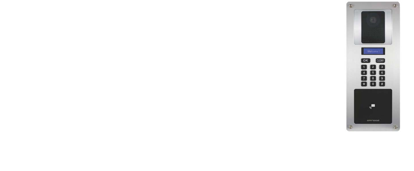
Figure 2: Single Unit Application
General Application of Door Entry System
There are two major models of Video Door Phone: one is single unit model, the other is community model. They are applied on
different conditions. Please see following descriptions:
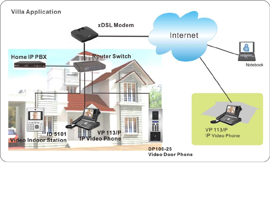
Villa Application
DP100-25 is designed for building,
apartment or community. It is also used
for single house or villa. Please see
Figure 2.
Using a home IP PBX to connect all
SIP-based devices.
Communicate with each device simply
with extension numbers.
Connect to SIP VoIP services via
Internet.
Community Application
DP100-25 is designed for building,
apartment or community.
Please see Figure 3
Connect each house or apartment
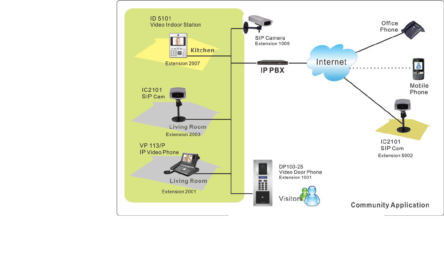
DP100-25 VIDEO DOOR PHONE
3
A
mroad Technolo
gy
Inc.
with a large IP PBX.
Residents can check
visitors, monitor public
areas or call each others
with extension numbers.
Connect to SIP VoIP
services via Internet.
Figure 3: Community Application
DP100-25 SI MANUAL
4
A
mroad Technolo
gy
Inc.
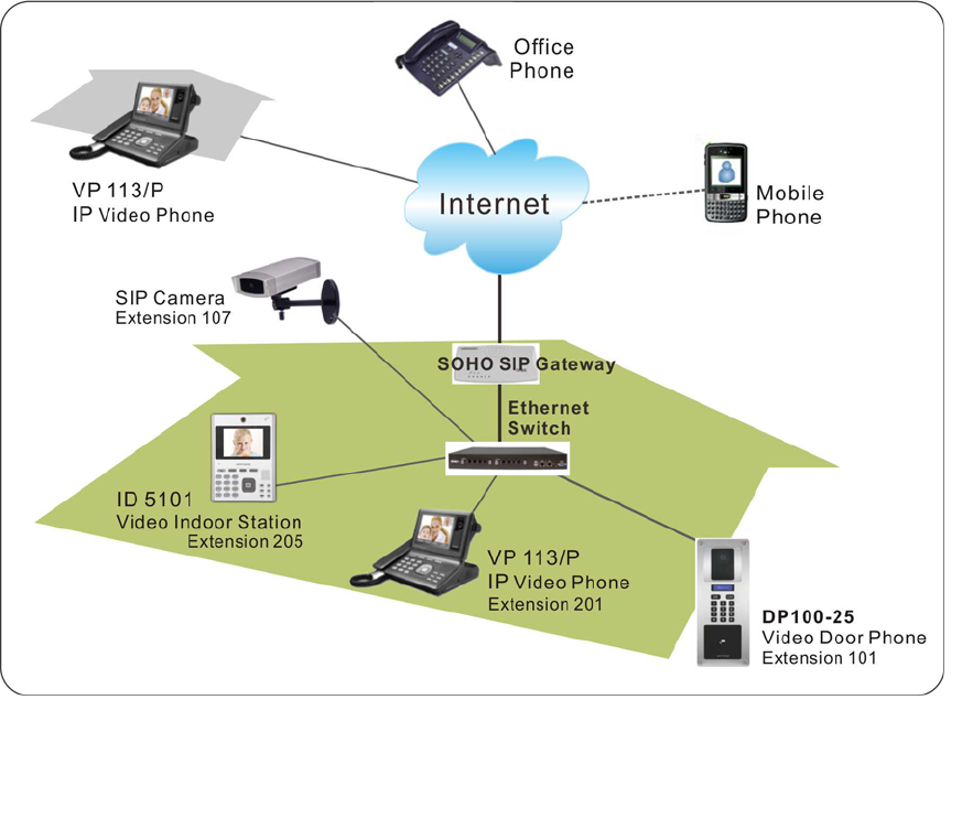
Use of SIP
SIP, initial of Session-Initiation-Protocol, it is an application-layer control (signaling) protocol for creating, modifying, and terminating
sessions with one or more participants. These sessions include Internet telephone calls, multimedia distribution, and multimedia
conferences. Simply say, SIP is a most commonly used protocol that used to interconnect SIP Enabled PBX and/or SIP User
Agents to each other to establish voice and
video sessions between each other over an IP
Network.
There are few typical applications of SIP
products, please refer to Figure 4
Make a video phone call from indoor IP
Video Phone to outside IP Video Phone.
Make a video phone call from softphone on
notebook to IP Video Phone.
View SIP Camera video from IP Video
Phone at office.
View SIP Camera video from you mobile
phone.
Figure 4: General SIP Application
DP100-25 VIDEO DOOR PHONE
5
A
mroad Technolo
gy
Inc.
Chapter 2 : Knowing Video Door Phone
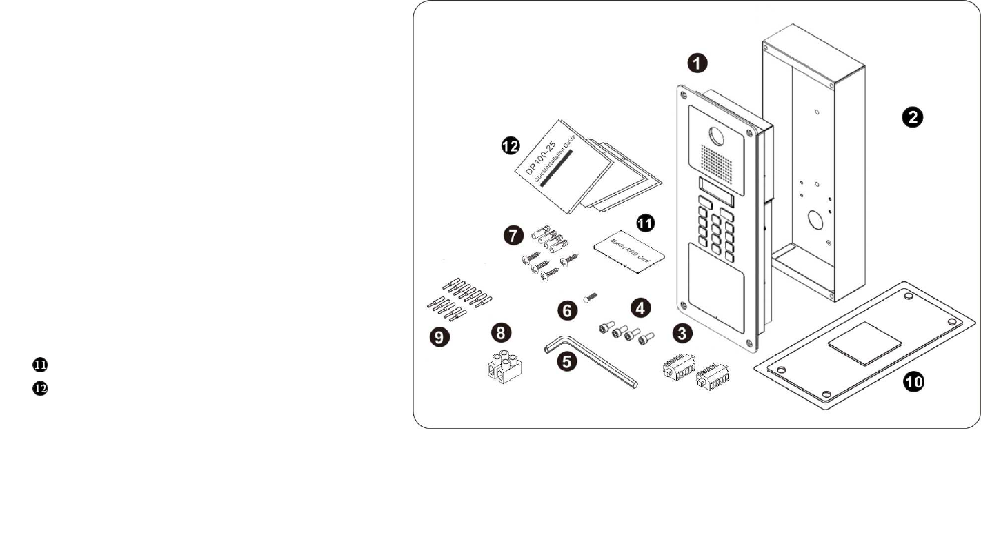
Package Contents
The following items are included in your Video
Door Phone package. Check this list before
installation to ensure that you have received all
items.
n Video Door Phone Unit
o Wall Mounting Box
p Terminal Connectors
q Screw Pack (4 pieces of M6 x 20mm)
\ Wrench
] Screw for Earth Wire
^ Wall mounted screw pack
_ H-type Terminal Connector for Power Wire
` Cord End Terminal (12 pieces)
a Plastic Protective Cover
Master RFID Card
Quick Installation Guide & Quick Start Guide
(Englis h/Chinese version)
Please contact your dealer immediately in case
that any item(s) is missing. Figure 5: Package Contents

DP100-25 SI MANUAL
6
A
mroad Technolo
gy
Inc.
DP100-25 VIDEO DOOR PHONE
7
A
mroad Technolo
gy
Inc.
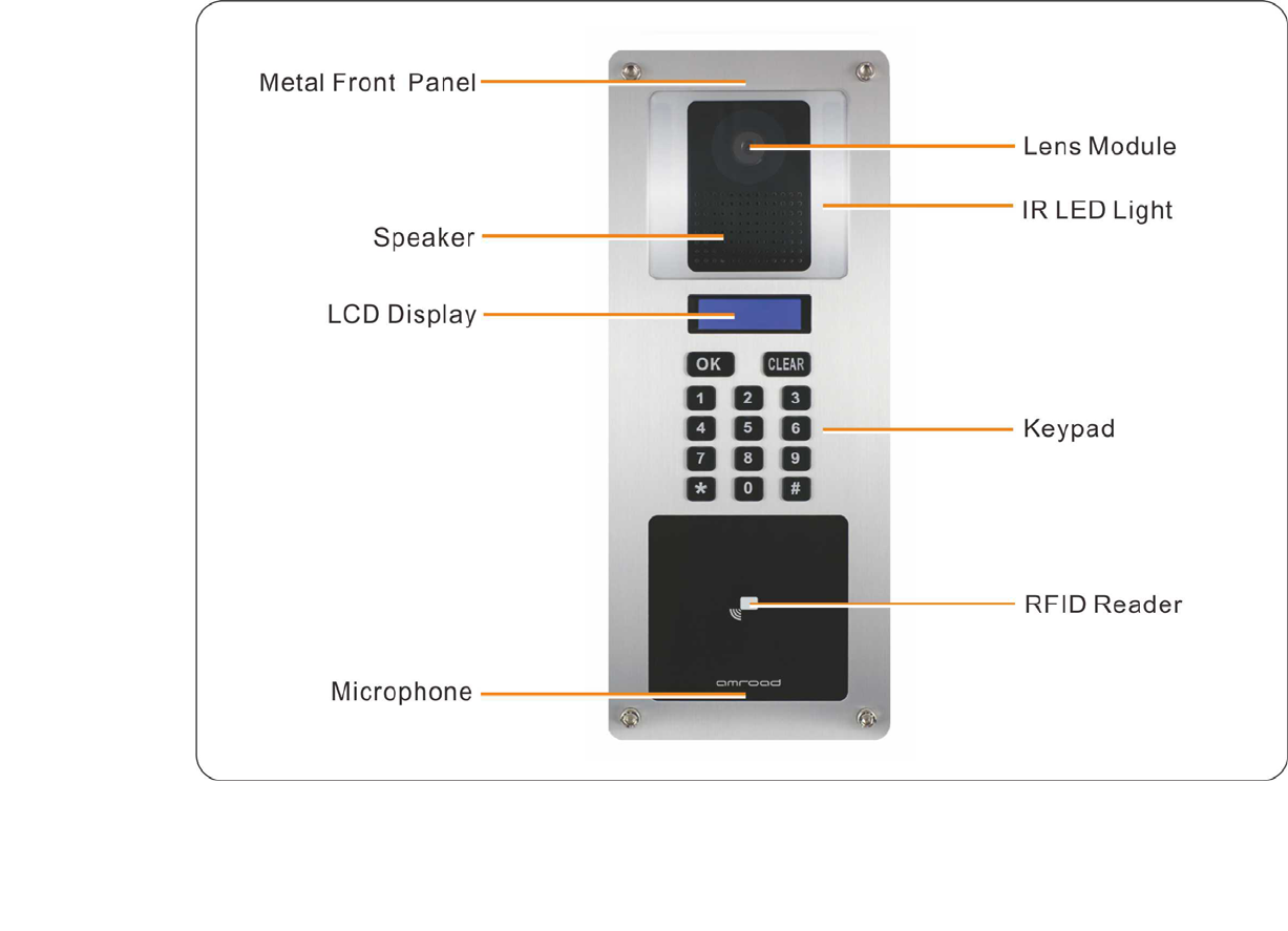
Front Panel
Figure 6: Front Panel

DP100-25 SI MANUAL
8
A
mroad Technolo
gy
Inc.
LED Light
There are IR LEDs on both sides of CMOS lens for light compensation. Blue LEDs are behind the keypads, and LCD screen
is with blue backlight. The LED and blue backlight will light when any button/keypad is pressed. And, the LED and backlight
can be set through WEB UI.
LEDWEBUISETTINGDESCRIPTION
SleepModeDisableTheblueLEDwilllightOnwhenanykeypadispressed.And,thekeypadLED
willbeturnedoffin5~10secondsafterphonecallisended.
KeypadLED
SleepModeEnableBeyondthetimeperiodofSleepMode,KeypadLEDwillalwaysbeON.
Backlight
OpenOnThebacklightwillalwayslightON.
LCDBacklight
Backlight
OpenOffTheLEDbacklightwilllightOnwhenanykeypadispressed.And,theLED
backlightwillbeturnedoffafteroneminuteafterphonecallisended.
DP100-25 VIDEO DOOR PHONE
9
A
mroad Technolo
gy
Inc.
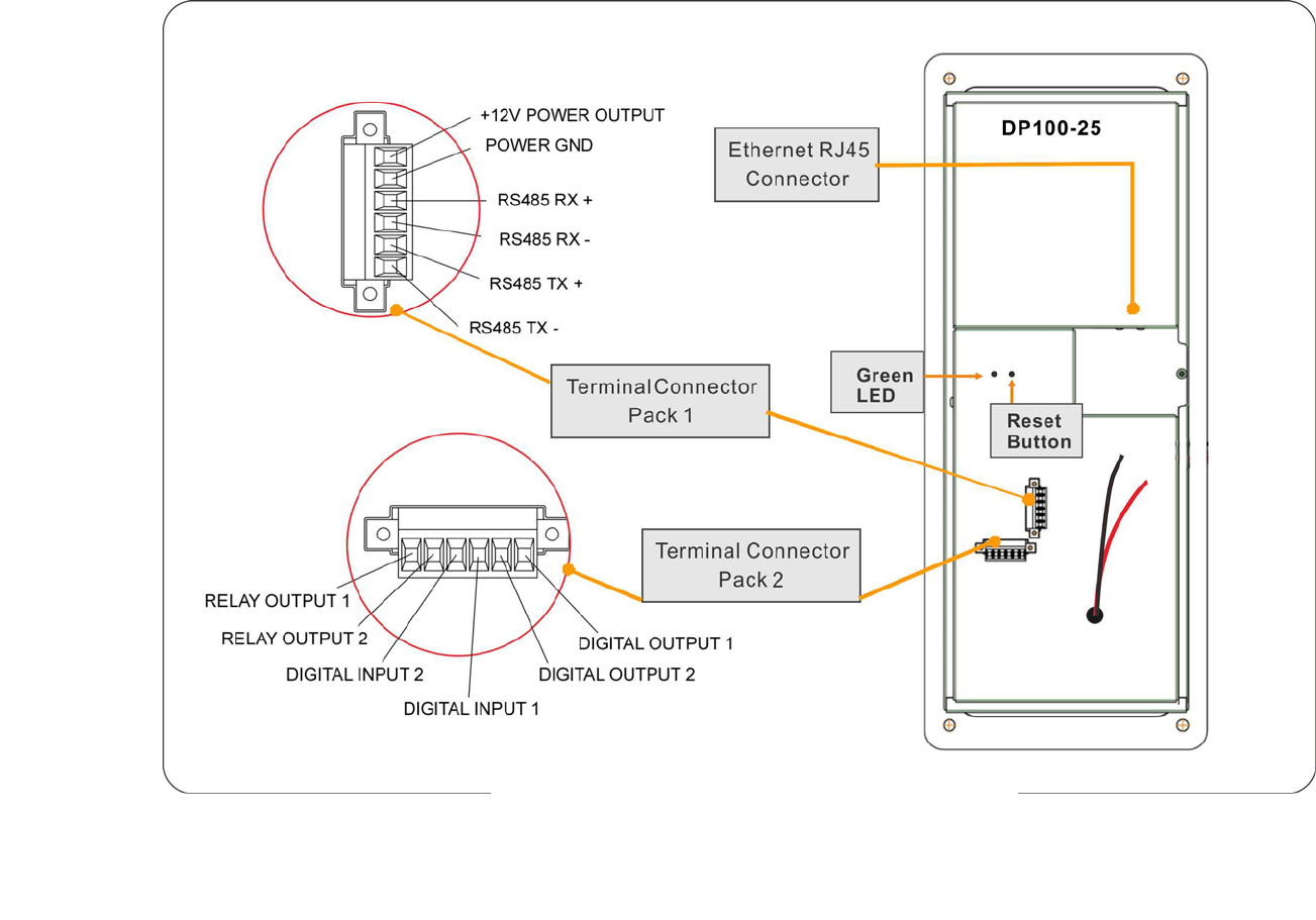
Rear Panel
Figure 7: Rear Panel and Connectors
DP100-25 SI MANUAL
10
A
mroad Technolo
gy
Inc.
Reset Button
The default IP type setting of Video Door Phone is “DHCP Client “.
1. Pressing the reset button for 3 seconds=>DP100-25 will turn into Statics IP mode as "192.168.0.50" and reboot by itself.
2. Pressing for over 6 seconds and Green LED ON=>Turn to DHCP mode as the default value and reboot by itself (Restore
to factory setting).
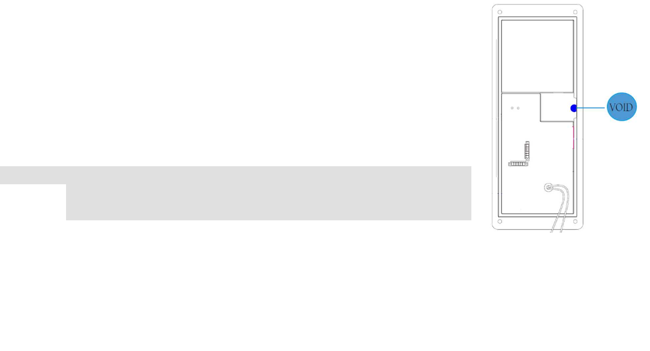
VOID Sticker
There is a “VOID” sticker on the rear side of the DP100-25.
This VOID sticker is used to prevent opening the case and tampering concealment.
WARNING: “VOID” means “WARRANTY VOID IF SEAL BROKEN”
Amroad shall not be responsible under warranty if the VOID sticker is
broken or removed.
Figure 8: VOID Sticker
DP100-25 VIDEO DOOR PHONE
11
A
mroad Technolo
gy
Inc.
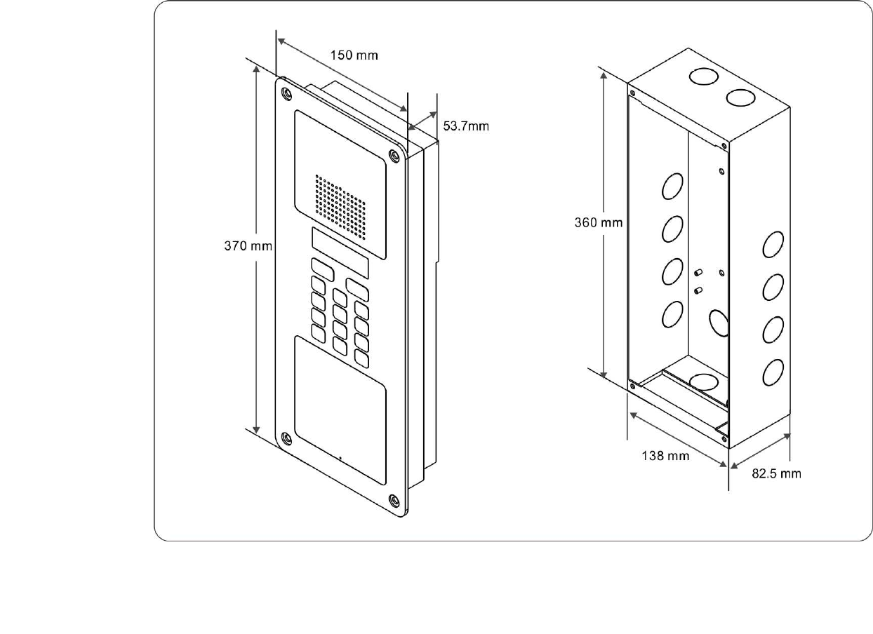
Dimensions
Figure 9: Dimensions
DP100-25 SI MANUAL
12
A
mroad Technolo
gy
Inc.
Chapter 3 : Installing Video Door Phone
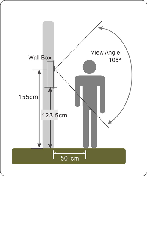
Suggested Installation Positions
Due to the view angle of the camera lens is limited, to install the Video Door
Phone in a correct position to get better view is very important. Suggested height
of the lens position is at the height of 155 cm according to building conditions.
And, the distance from the bottom of wall box to the ground is 123.5 cm. View
angle of this door phone is 105
O. Please see an example of installation position on
Figure 10.
Lighting Conditions
The Lens of this device is able to see IR (Infra-Red) light, therefore you may also
implement with an IR light. Please note, IR light only delivers black & white
images, and the objects looks odd in some conditions. Please see the spotlight
example on Figure 10.
Figure 10: Installation Position
DP100-25 VIDEO DOOR PHONE
13
A
mroad Technolo
gy
Inc.
Installing Procedures
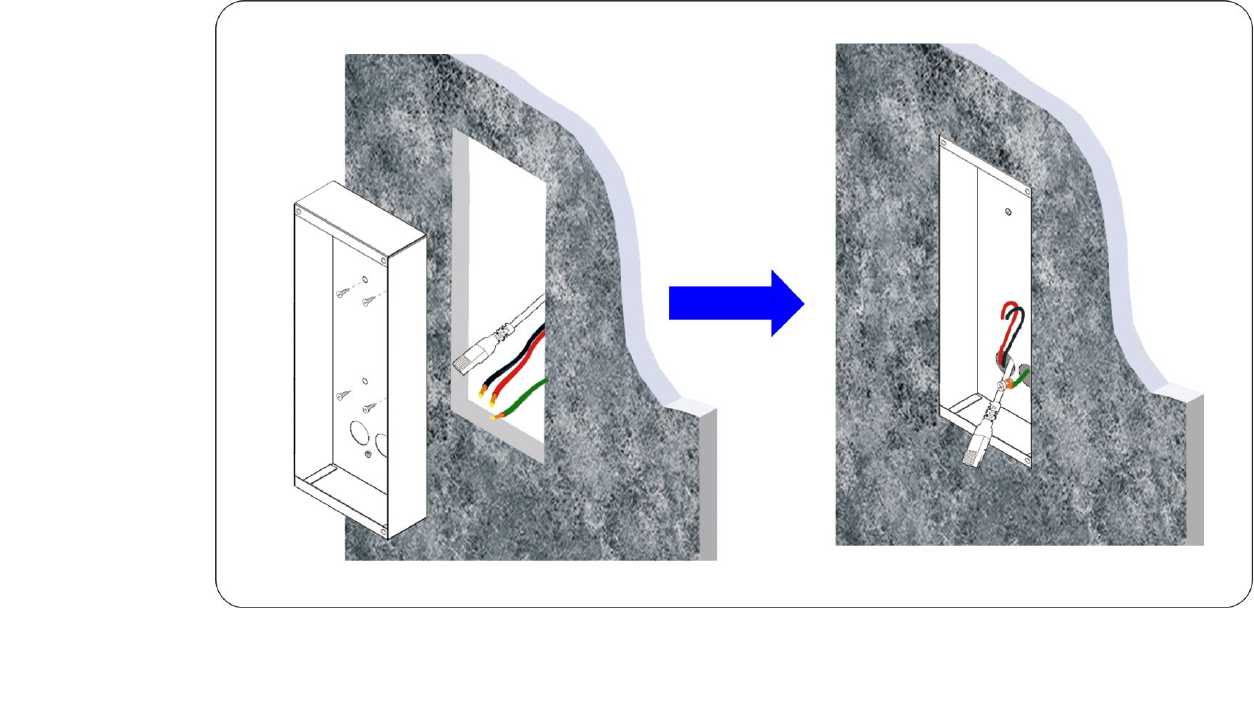
1. Insert the Wall Mounting Box into the Wall.
Cutting a hole that is able to contain the Wall Mounting Box and prepare the DC +12V and Ethernet cable ready. Then insert
the box into the wall and pull the DC wires and Ethernet cable through the hole on the box. You must place the Box very
precisely in horizontal in order to keep the Video Door Phone in correct position.
Figure 11: Installing the Wall Mounting Box
DP100-25 SI MANUAL
14
A
mroad Technolo
gy
Inc.
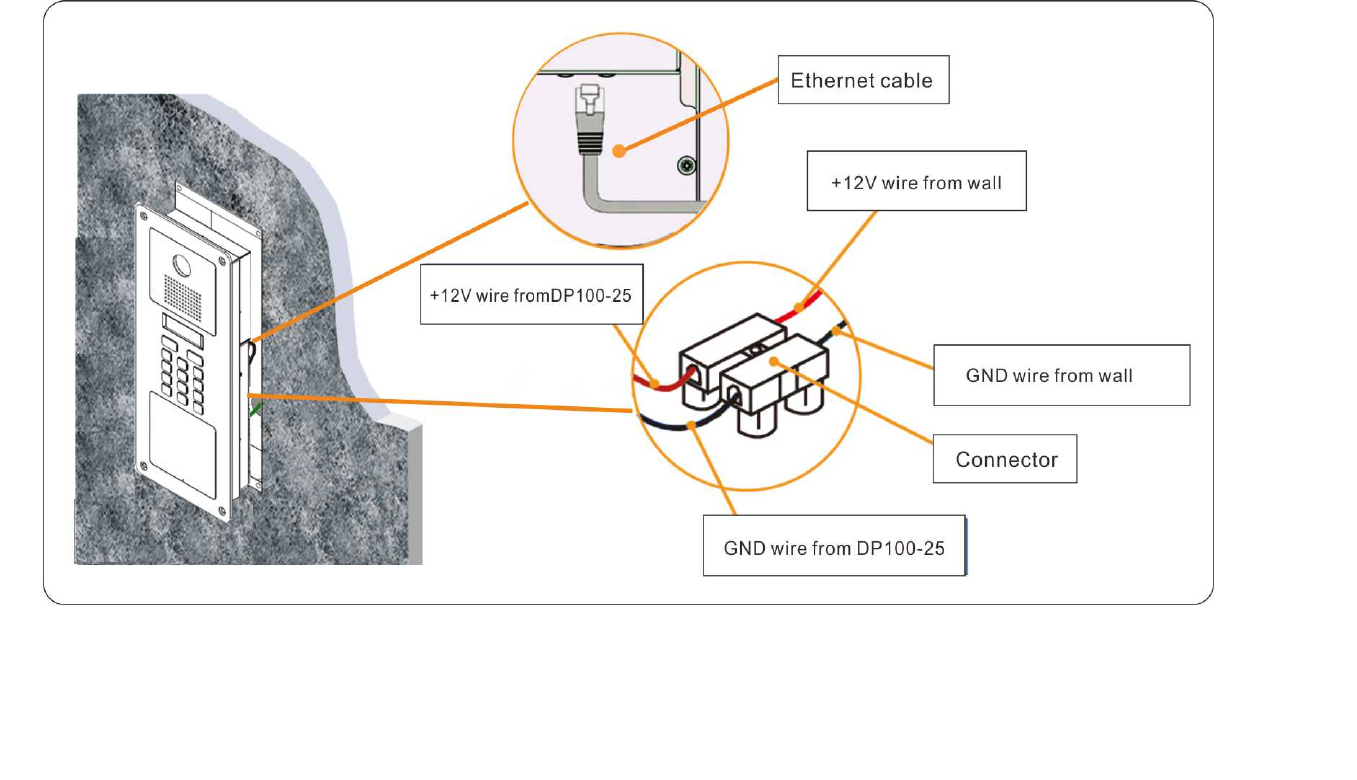
2. Connect the DC wires and Ethernet Cable.
Connect the DC wire of DP100-25 to H-type power connector, and connect Ethernet cable to DP100-25 according to below
Figure 12. Please be careful when you are connecting the DC +12V, be sure to check the DC condition before you start to
connect the wires. Please screw the earth cable to the “Wall Mounting Box “.
Figure 12: Connecting Cable & Wires
DP100-25 VIDEO DOOR PHONE
15
A
mroad Technolo
gy
Inc.
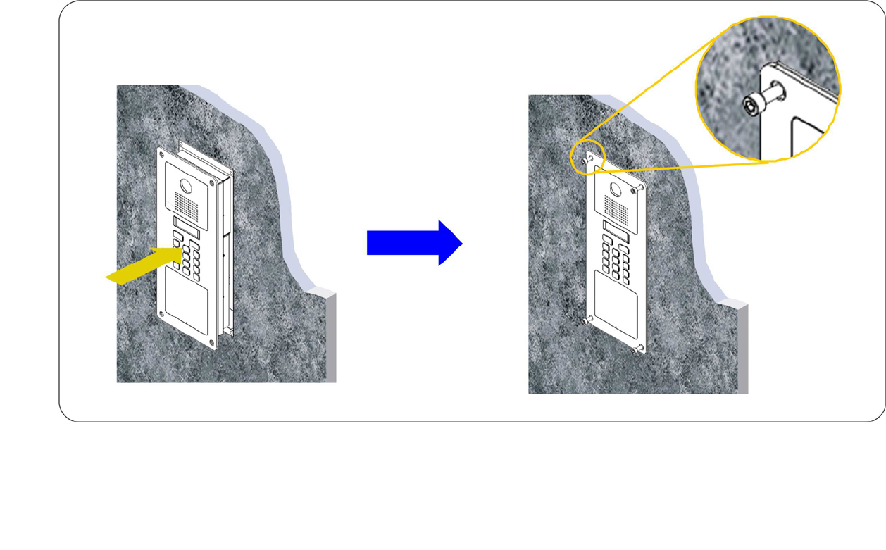
3. Install Video Door Phone into the Mounting Box.
After properly connecting the wires and cables, insert the Video Door Phone into wall mounting Box carefully. Then screw the 4
screws that come with the package into the front panel. Please double check all the installation procedure again, and you may
power on and start the configuration procedures.
Figure 13: Insert the Video Door Phone
DP100-25 SI MANUAL
16
A
mroad Technolo
gy
Inc.
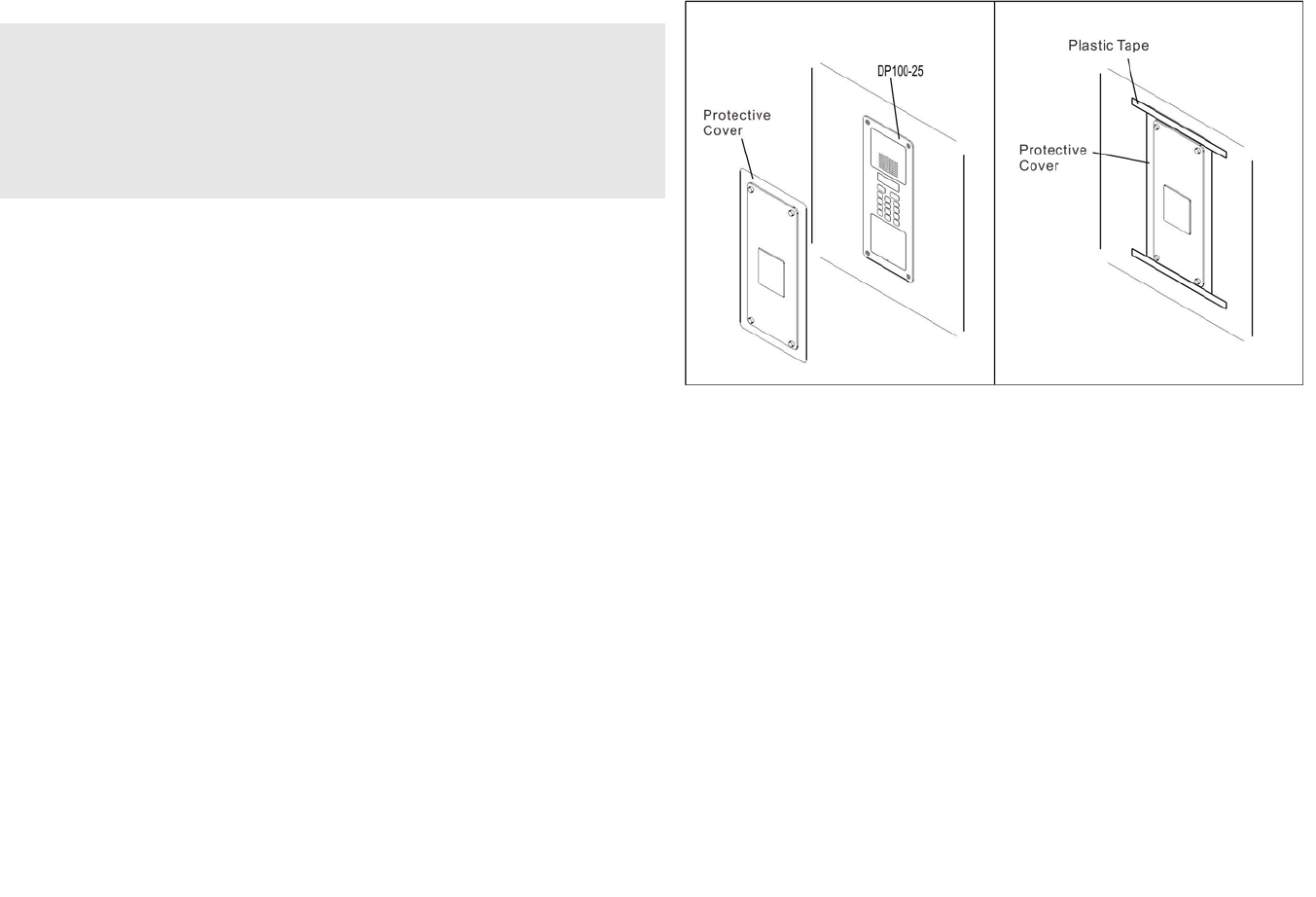
NOTE: We suggest that the protective cover should be attached
to DP100-25 and should not be torn up after DP100-25
installation. Do not tear up the protective blister until
residents of community/building begin to use DP100-25
Video Door Phone.
Figure 14: Don’t remove Protective Cover

DP100-25 VIDEO DOOR PHONE
17
A
mroad Technolo
gy
Inc.
DP100-25 VIDEO DOOR PHONE
19
A
mroad Technolo
gy
Inc.
Chapter 4 : Configuring Video Door Phone
Finding Video Door Phone on Networks
This chapter describes how to configure your Video Door
Phone via Web User Interface. Before proceeding
configuration, you have to locate the Video Door Phone on
the network. You may find out the IP address of this device on
the LCD display. NOTE: By pressing “#” key on front panel,
you will see IP address like on Figure 16.
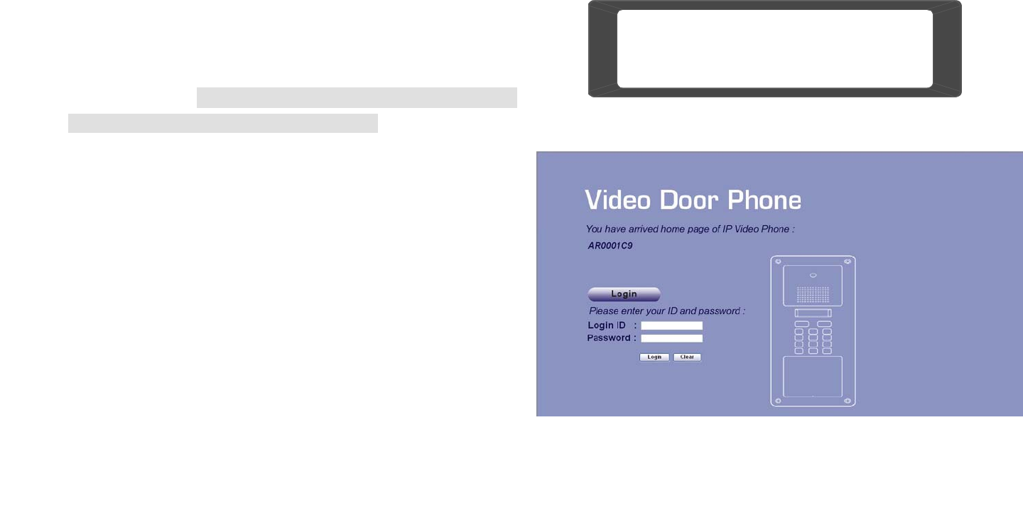
Input the IP address of this product on your browser, then you
will see home page of the Video Door Phone like Figure 17.
Web UI is protected by Login ID and Password. Press the
“Login” button, then you will see 2 input fields: Login ID and
Password. Please key in the correct ID and password, and
then press second “Login” button to enter Web UI. The
default ID and password are:
Login ID: admin
Password: admin
Figure 16: Login Web UI
Figure 15: IP Address on LCD
IP Address
10.3.1.76

DP100-25 SI MANUAL
20
A
mroad Technolo
gy
Inc.
NOTE:1. While configuring WEB UI (User Interface), please do not operate this product so as to prevent this product from
being out of order.
2. Do not input special symbols “, \, and & in the fields on the WEB UI. Otherwise, you will fail to save your setting
normally.
3. After configuring some Web pages and pressing “SAVE” button, you need to wait a little longer for system to save the
configuration.
DP100-25 VIDEO DOOR PHONE
21
A
mroad Technolo
gy
Inc.
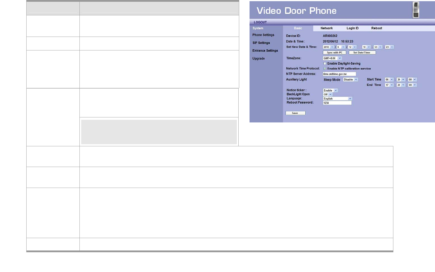
System - Basic Settings
This field allows you to select your time zone to fit
your location. You can enable the
Daylight-Saving feature if needed.
Time Zone
NOTE: Daylight Saving Time is a way of getting
more light out of the day by advancing
clocks by one hour during the summer.
Network Time
Protocol Enable this protocol allows the system to calibrate the time with NTP server through Internet.
NTP Server
Address You may use your preferred NTP server by input new address here.
Auxiliary
Light This item allows you to control keypad lighting device.
Sleep Mode: When you enable this function, the keypad will not light during following time period
except when any keypad is pressed.
Start Time: You may set Start Time for each day.
End time: You may set End Time for each day.
Notice Ticker Enable this feature to show “Please Press OK to Operator!” in the LCD screen by setting “Mapping
Item Description
Device ID This ID is a unique number that assigned by
manufacturer.
Date & Time Here shows date and time set on this phone.
Set New Time
and Date These fields allow user to set correct date and
time according to the local–standard. You may
synchronize phone time to match your PC by
pressing “Sync with PC” button.
Figure 17: System - Basic Settings

DP100-25 SI MANUAL
22
A
mroad Technolo
gy
Inc.
Number” in Web “Extension number” page in advance.
Back Light
Open Select “On” to turn on the Back Light of the LCD always.
Select “Off” to turn on the Back Light when any keypad is pressed.
Language This feature allows you to select the display language on the LCD screen.
Select “English” or “Traditional Chinese”
Reboot
Password This feature allows you to reboot the DP100-25. When you are pressing “CLEAR” button for 15
seconds, you get the “Input Password” indicator then input the password and press OK button.
Default password is “1234”. And further, the feature also allows you to turn IP-Type into the Static IP
(192.168.0.50) for debug/setting purpose. The process is same as the previous one, only the
password is different; you need add “00” in the ending for password checking. I.e. Default
password is “123400”.
Save Click this button to save your setting.
DP100-25 VIDEO DOOR PHONE
23
A
mroad Technolo
gy
Inc.
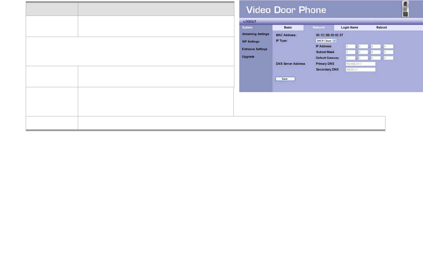
System – Network Settings
Item Description
MAC Address This is a quasi-unique identifier attached to most
network adapters.
IP Type
The default value is DHCP Client.
There are two options: DHCP Client and Static IP.
A. DHCP Client: The system will automatically
assign you an IP address.
B. Static IP: you have to input IP address,
Subnet Mask, Default Gateway, Primary DNS
and Secondary DNS data.
Save Click this button to save your setting.
Figure 18: System - Basic Settings
DP100-25 SI MANUAL
24
A
mroad Technolo
gy
Inc.
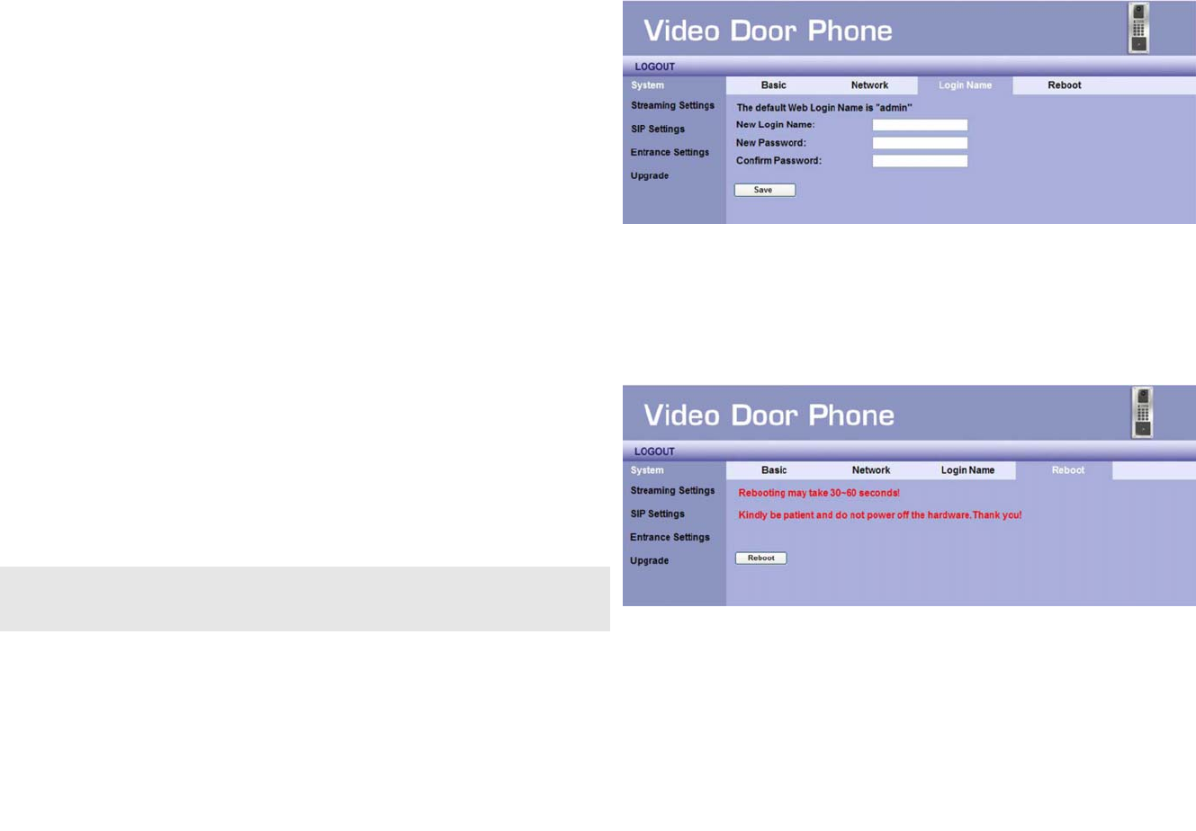
System Login Name
The default ID and password for system login are admin and
admin.
User may change his Login ID and Password on the webpage
by entering new Login ID and Password.
System Reboot
When user needs to reboot DP100-25 remotely, just click
“Reboot” button on this webpage to start this action. After
confirm rebooting, Web User Interface will back to the home
page, but the video door phone may take 30~60 seconds to
restart its system.
NOTE: DO NOT operate the DP100-25 while system is
rebooted (reset).
Fi
g
ure 20: S
y
stem Reboot
Fi
g
ure 19: S
y
stem Lo
g
in ID Settin
g
s
DP100-25 VIDEO DOOR PHONE
25
A
mroad Technolo
gy
Inc.
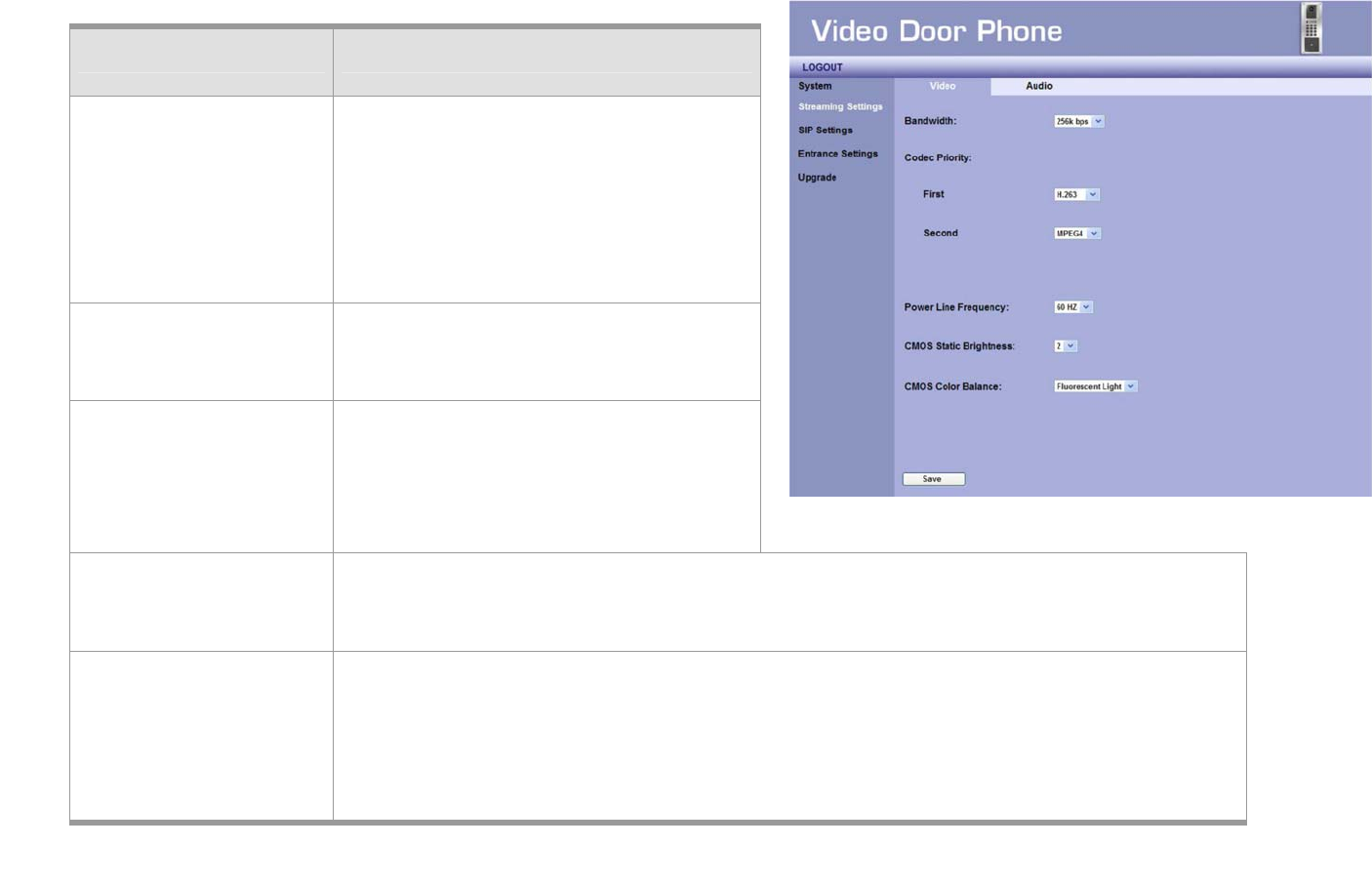
Phone Settings – Video
You may set change the video settings in this page.
ITEM Description
Bandwidth You may select preferred bandwidth for
video and audio streaming. There are 4
options: 128Kbps, 256Kbps, 384Kbps,
and 512Kbps. Please check which
bandwidth is suitable for you with your
service provider.
Codec Priority You may select priority of video codec
here:
H.263 – will authenticate H.263 first
Power Line
Frequency
You may select the power frequency
according to your local power
specifications. Wrong power frequency
may cause the video flicking
abnormally.
CMOS Static
Brightness This item allows you to adjust the brightness of CMOS according the lighting
environment of the installed location. There are 10 levels of value in this item. Higher
value makes the video brighter.
CMOS Color Balance This item allows you to adjust the color conditions. Since the Lens of this product is
able to take Infra-Red light, it may affect the color of video. You may select a suitable
condition from: Fluorescent Light, Yellow Lamps and Orange Lamps.
z Fluorescent Light – This condition is suited for white lighting environment.
z Yellow Lamps – This condition is suited for indoor yellow bulb environment.
Fi
g
ure 21: Video Settin
g
DP100-25 SI MANUAL
26
A
mroad Technolo
gy
Inc.
z Orange Lamps – This condition is suited for indoor orange color or more red
color environments.
Save Click this button to save your setting.
<IMPORTANT>: “Turn on/off IR LED” and “adjust the brightness of CMOS” via Amroad IP Video phone, DP100-25 can’t get the
correct value of the CMOS brightness in some environment, please adjust the brightness value via the Amroad IP
Video Phone by pressing “2”(brighter) or “8”(darker) in conversation state.
DP100-25 VIDEO DOOR PHONE
27
A
mroad Technolo
gy
Inc.
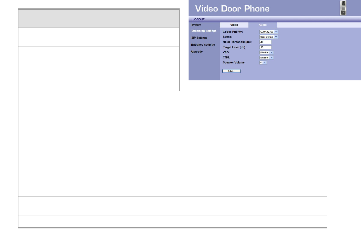
Phone Settings – Audio
ITEM Description
Code Priority You may select the Audio streaming
priority – G.711.
You may select the AEC (Acoustic
Echo Control) scene according the
environment of the installed location.
Select “Disable”, ”Default” or “User
Define”.
Scene
When “User Define” is selected, the following two items appears:
Noise Threshold (db): Default: -40. The voice intensity that is lower than the value (-40db)
will be neglected. (Acceptable value -40~-52)
Target Level (db): Default: -23 The voice intensity that is around normal intensity will be
processed to be the value (-23db). (Acceptable value
-20~-32)
VAD You may enable or disable Voice-Active-Detection function here. The DP100-25 will detect
background noise and send silence packet to the other end if this feature is enabled. This
allows called parties hear better audio quality.
CNG You may enable or disable Comfortable-Noise-Generate function here. The DP100-25 will
generate background noise when receiving silence packet from the other end if this feature is
enabled. This allows called parties hear better audio quality.
Speaker
Volume This item allows you to select volume of speaker. There are 10 levels, 0 ~ 9.
Save Click this button to save your setting.
Figure 22: Audio Setting

DP100-25 SI MANUAL
28
A
mroad Technolo
gy
Inc.
DP100-25 VIDEO DOOR PHONE
29
A
mroad Technolo
gy
Inc.
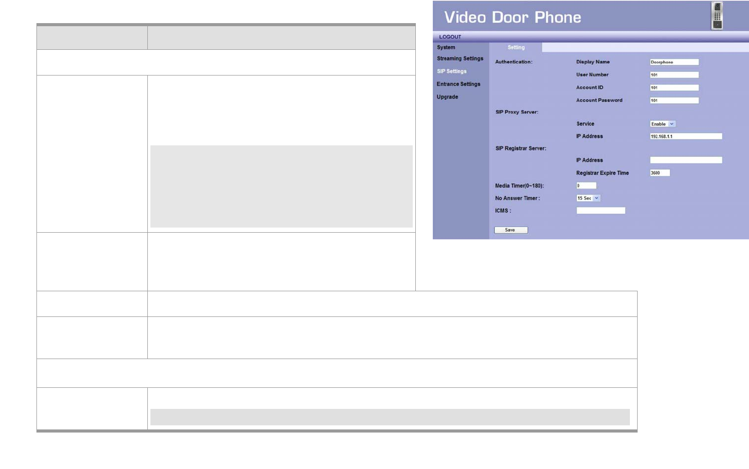
SIP Services
You may setup advanced SIP service parameters in this page:
Item Description
Authentication
Display Name This name will show on the IP phones of called
parties. You can fill in the preferred name here.
For example, Doorphone
NOTE: Please enter Doorphone in the field of
Display Name. When the Door Bell is
pressed, there will be “Preview”
function and Doorbell sound on Amroad
IP Video Phone/Video Indoor Station.
User Number You may fill in the phone number here, normally
it is provided by service provider. To work with
IP PBX, you may fill in extension number.
Account ID You may fill in your account name of SIP service in this field. For example, 101
Account
Password
You may fill in the password of your SIP service account. For example, 101
SIP Proxy Server
Service You may select “Enable” to connect other devices in SIP mode.
NOTE: For Peer-to-Peer mode, both devices (DP100-25 and remote device) need to
Figure 23: SIP Settings
DP100-25 SI MANUAL
30
A
mroad Technolo
gy
Inc.
select Disable in the dropdown menu. And, fill in each other’s IP address.
IP Address You may fill in the IP address of SIP Proxy Server in this field.
SIP Registrar Server
ITEM Description
IP Address You may fill in the IP address of SIP Registrar Server here.
Registration
Expire Time Set the time for SIP registration authorization
The default is 3600 seconds.
Media Timer
(0~180) This setting allows your phone to force release automatically a conversational call when
your phone doesn't receive any media packets from the remote side during a period of
time. If you want to disable this feature, please fill in "0" sec.
No Answer Timer When visitor presses the door bell and no one answer the call, the bell sounds
(Ding-Dong) will continuously ring for a time period. You may select the time period-
15sec, 30sec, 45sec, or 60sec. Default is 15 seconds.
NOTE: The setting is based on your IP PBX.
ICMS Input the IP address of ICMS. This function is customized and it allows DP100-25 to
send pictures of visitors to ICMS.
Save Click this button to save your new setting.
DP100-25 VIDEO DOOR PHONE
31
A
mroad Technolo
gy
Inc.
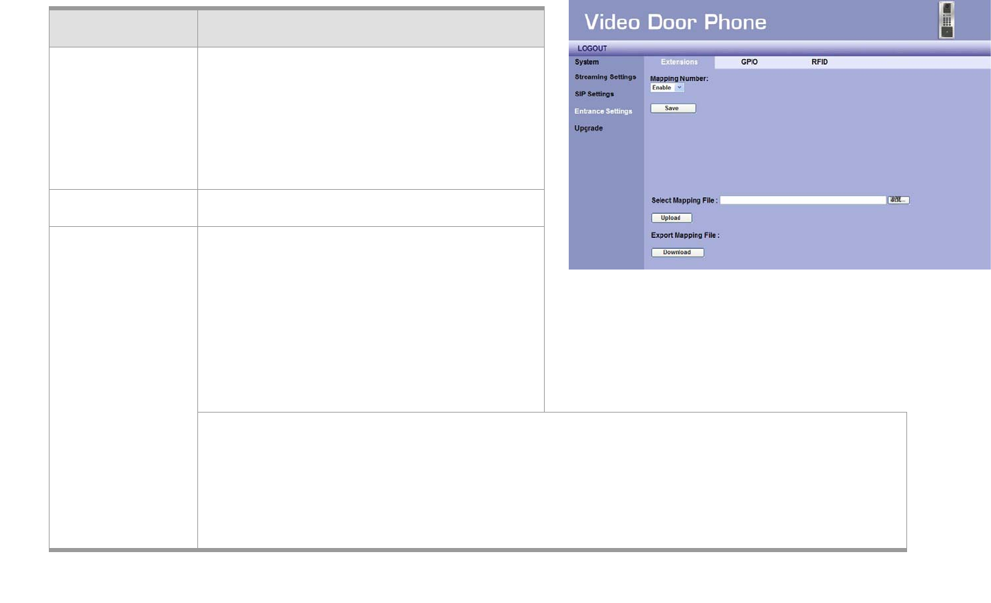
Entrance Settings – Extensions
You may configure call services in this page:
ITEM Description
Mapping
Number
Select “Enable” to allow you use a real house
number instead of extension number
assigned from IP PBX. For large community,
it is easier for visitors to enter the real house
numbers than extension numbers.
Save Click this button to save your setting.
Once you enable the Mapping Number
feature, you may import the mapping table
from this field. You may edit the mapping
table in WordPad or Notepad, and then save
as “csv” format. The format must match
following style, otherwise the firmware may
not recognize these data:
Select Mapping
File
Name, uri ,commit, comm_id
#1,101 ,101-1F,0
#2,102,102-1F,0
#3,103,103-1F,0
#4,104,104-1F,0
Figure 24: Extensions

DP100-25 SI MANUAL
32
A
mroad Technolo
gy
Inc.
#5,105,105-1F,0
#6,106,106-1F,0
#7,107,107-1F, 0
#8,108,108-1F, 0
0,1000,The Operator,1
1202,1001,First St No120 3F,2
1203,1002,First St No.120 4F,3
1204,0282265688,Outbond Call,4
Where “blue” part is necessary for the file, please add your mapping number in their following.
The title of each column must be exactly same as above sample, hereunder are explanations of
each column title:
“name” – This column is the number that you wish visitors to input on the Video Door
Phone keypad. Where the value is “0” means ‘Notice ticker’ service can be
enabled – it indicates “Please Press OK to Operator!” on the LCD screen. When
you press OK, DP100-25 will dial the corresponding number.
“uri” – This column is the extension number of IP PBX or a Uniform Resource Identifier
which is a compact string of characters used to identify or name a resource on
the Internet.
“commit” – This column is for mark resident data such like address. Please note, you
cannot use comma “,” inside the column when you want to mark the address.
“comm_id” - This column is for input serial number of the records. Please start from 1.
<IMPORTANT>: Please note, total characters include punctuation marks and space of each
record (Line) MUST NOT over 80 characters. Recommended record number is less than 500.
DP100-25 VIDEO DOOR PHONE
33
A
mroad Technolo
gy
Inc.
After selecting the CSV file, you can press “Upload” button to start the uploading.
Export
Mapping File This item allows you to export existing mapping file (*.CSV) from DP100-25. The exported
mapping file may be a good example for you.
Press “Export” button to start exporting existing mapping file and save on your computer.
DP100-25 SI MANUAL
34
A
mroad Technolo
gy
Inc.
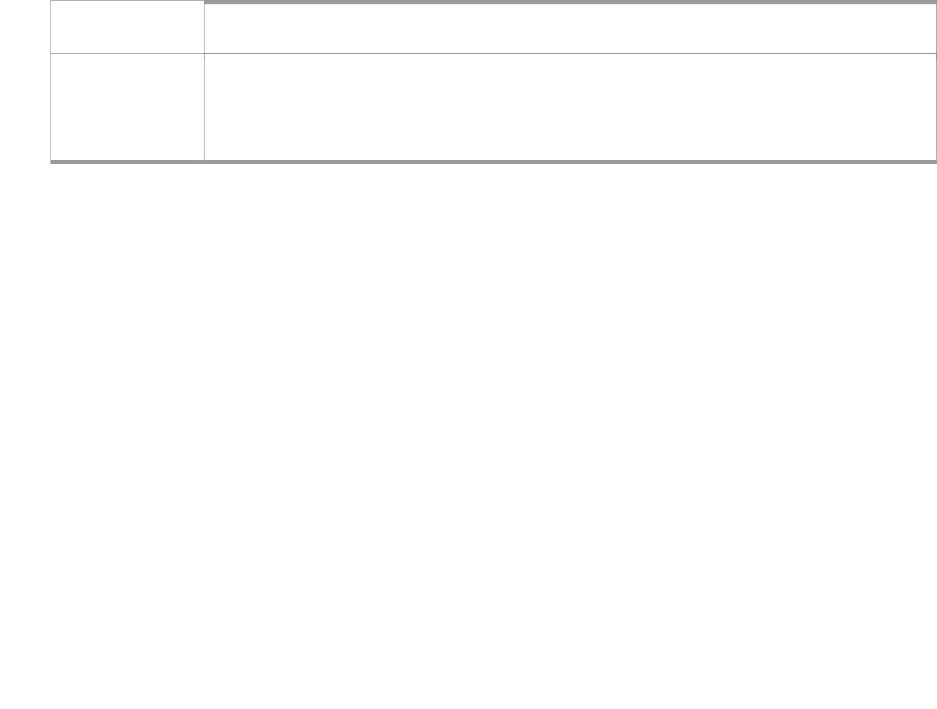
Entrance Settings – GPIO
You may configure GPIO in this page:
ITEM Description
Device Relay
Output Select “Positive” or “Negative” to connect
to Positive (Electronic Bolt) or Negative
(Electronic Strike) - triggered Electronic
Door Lock.
Press “#” to
unlock by
Press the “#” key a few seconds from your
Amroad IP Video Phone or Video Indoor
Station can trigger the function during
answering the phone call.
You can select the timer here.
“Immediately”, ”One Second”, ”Two
Second”, and “Disable”.
Save Click this button to save your setting.
NOTE: Be careful with the wires connection of GPIO, especially the default polar voltage of hardware (digit output
pins) is high. Please select and set the related electric circuit to meet the hardware initial voltage.
Figure 25: GPIO Setting
DP100-25 VIDEO DOOR PHONE
35
A
mroad Technolo
gy
Inc.
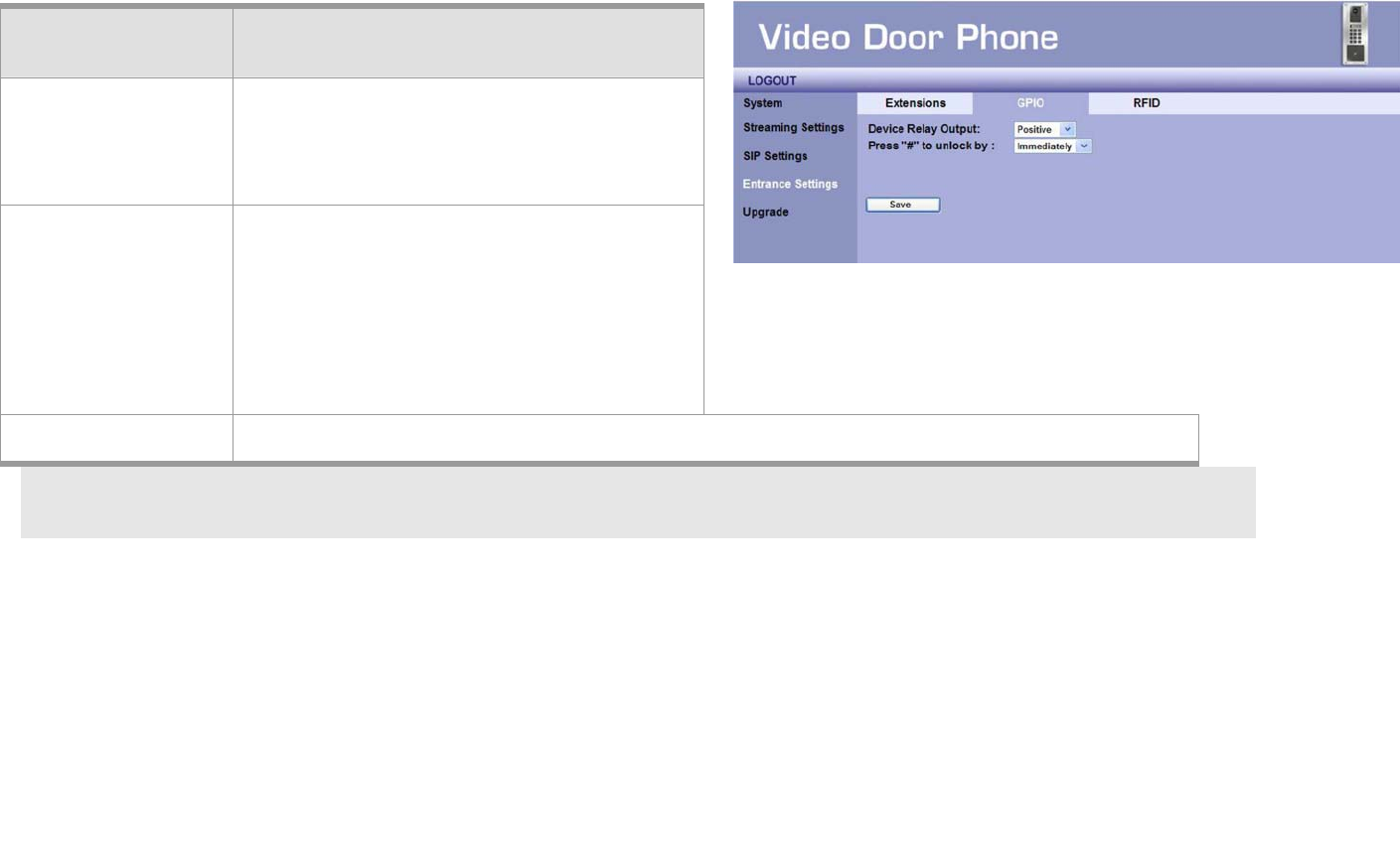
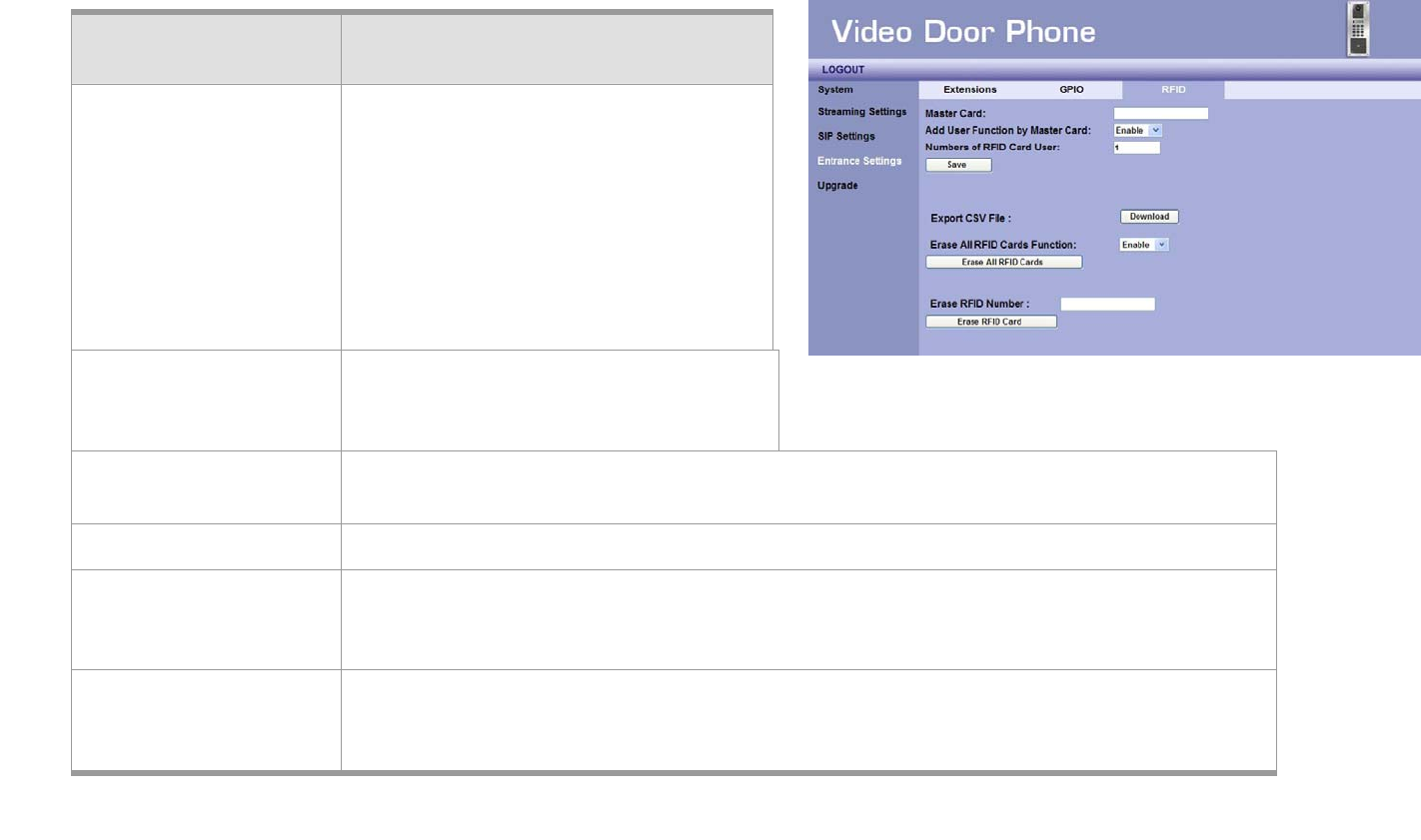
Entrance Settings –RFID
You may get the related RFID information and delete the
issued RFID Cards here.
ITEM Description
Master Card The master RFID card can issue new
cards for new tenants.
This field will display the card number
of the Master RFID Card. By default,
this field is null.
Scan a new RFID Card for the first
time, and it will be set as Master RFID
Card.
Adds User Function
by Master Card
Select “Enable” to let the Master RFID
Card be able to issue new cards for the
new tenant.
Numbers of RFID Card
User The number of RFID cards that are issued.
Save Click this button to save your setting.
Export CSV File Click Download button to export CSV file to open or save the file Card_No.csv on
your computer. All issued RFID card numbers from the Video Door Phone will be listed
in the CSV file.
Erase ALL RFID
Cards Function To delete the records of issued RFID card numbers can be executed here.
When the function is set “Enable”, it allow user to erase all RFID card numbers or
specific RFID card number.
Figure 26: RFID
DP100-25 SI MANUAL
36
A
mroad Technolo
gy
Inc.
The item Erase RFID Number will appear. Then, you may input the specific issued
RFID card number to delete it.
DP100-25 VIDEO DOOR PHONE
37
A
mroad Technolo
gy
Inc.
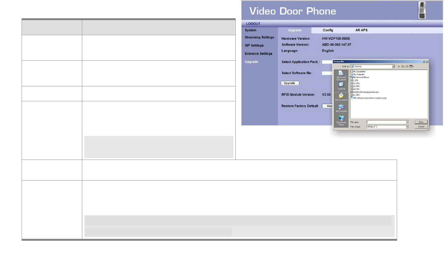
Upgrade – Firmware Update
The Upgrade function allows you to upgrade firmware of the
DP100-25. The ways to upgrade the firmware are via Web
UI.
Item Description
Hardware
Version
This field is to show firmware version number.
Software
Version
This field is to show current firmware version
number.
Language This field displays the Language Pack.
Select
Application
Pack
Press “Browse” button and select Application
Pack from your local disk.
NOTE: Application Pack and Software File
should be uploaded at the same time.
Select
Software File You may press Browse button to pop up a File dialog box to select the location of the new
firmware that you wish to upgrade.
Upgrade After select the new firmware, you can press Upgrade button to start the upgrading. You will see
progress bar showing the upgrade status.
WARNING: DO NOT turn off or disconnect the Ethernet cable during upgrade, you may cause
serious damage to this device.
Figure 27: Firmware Upgrade
DP100-25 SI MANUAL
38
A
mroad Technolo
gy
Inc.
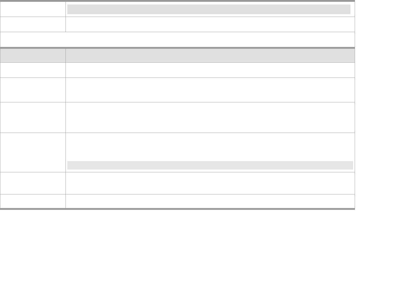
RFID Module
Version This field displays the version of the RFID Module.
Restore
Factory Default Press the Restore Default button and wait for system to restore its original factory default
setting.
DP100-25 VIDEO DOOR PHONE
39
A
mroad Technolo
gy
Inc.
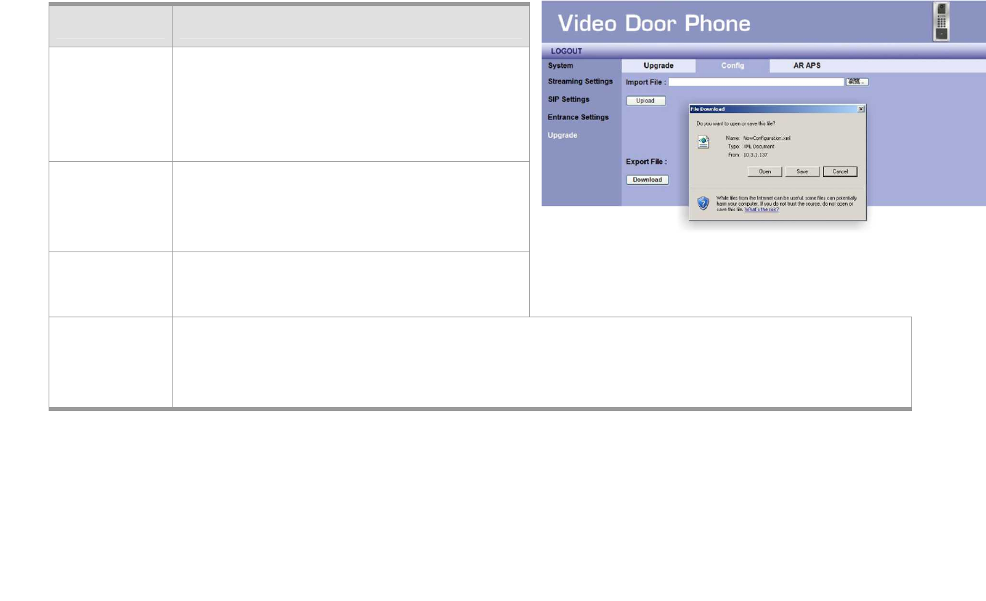
Configurations
Item Description
Import File User may press Browse button to select the
location of the configuration file to import,
which you may previously save to a local
directory through the Export File option.
Upload After selecting the configuration file, you can
press Upload button to start the importing.
Export File You can also use Export File to back up
DP100-25 settings on your computer.
Download Press Download button to export, and you are prompted to click “Open” or “Save” for
NewConfiguration.xml.
If you click Save, the configuration file will be saved into a local directory.
Figure 28: Configuration
DP100-25 SI MANUAL
40
A
mroad Technolo
gy
Inc.
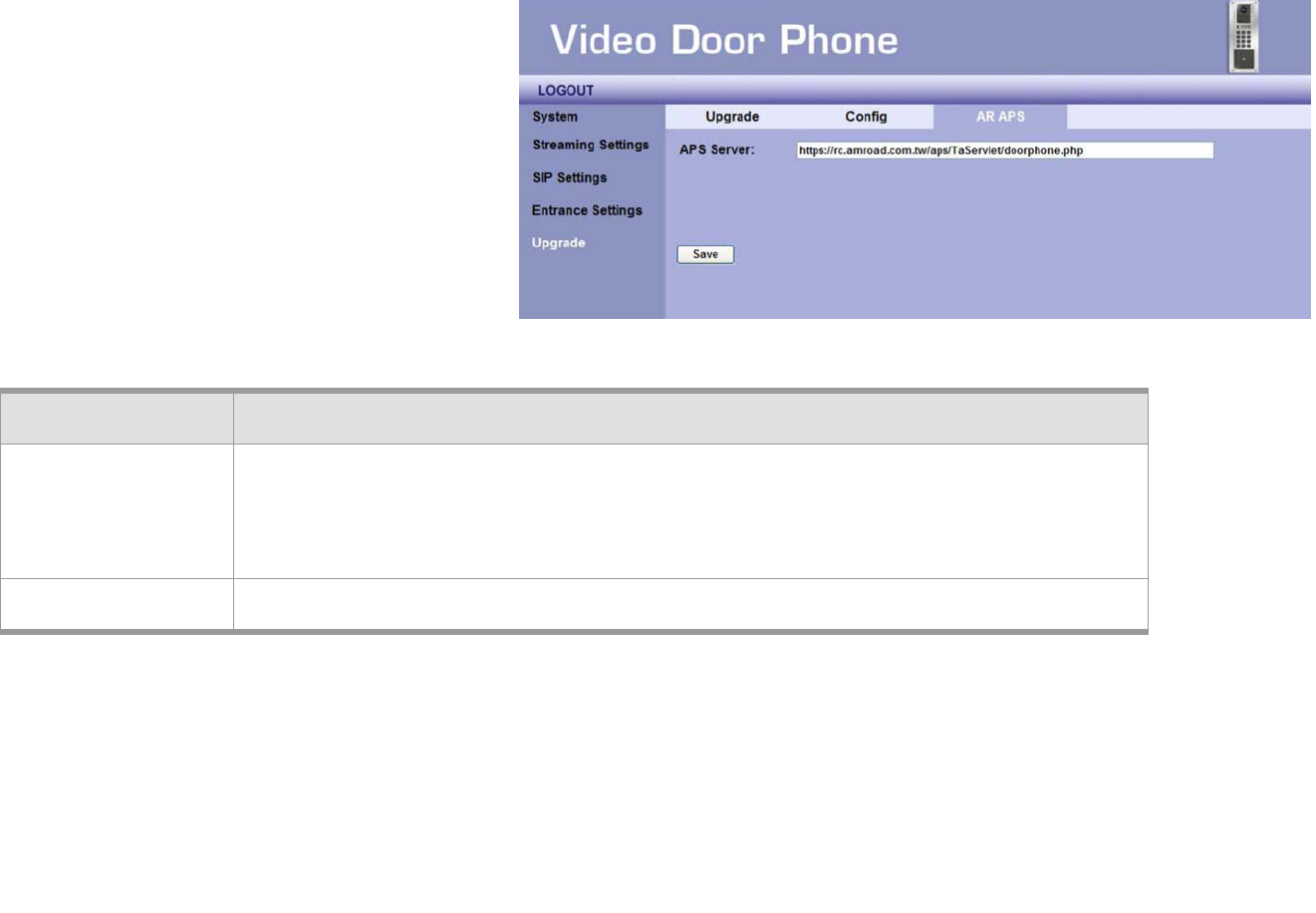
AR APS
This webpage allows manufacturing factory
to perform management function through
APS (Auto Provision Server).
Item Description
APS Server: This allows you to upgrade firmware of DP100-25 through network.
For example,
APS Server: https://rc.amroad.com.tw/aps/TaServlet/doorphone.php
Save Click this button to save your setting.
Figure 29: Auto Provision Server
DP100-25 VIDEO DOOR PHONE
41
A
mroad Technolo
gy
Inc.
OK
OK
OK
Welcome!
1001
Calling
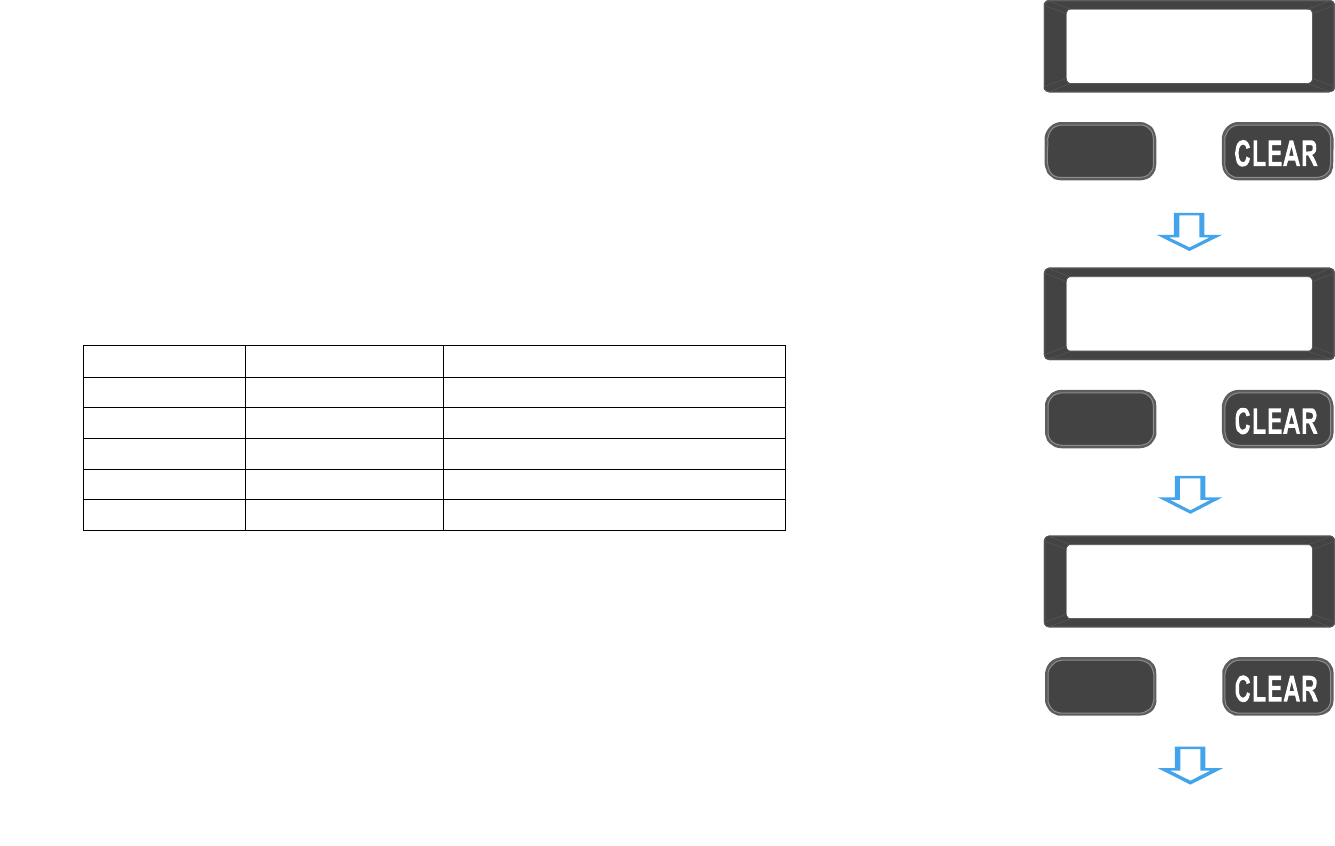
Chapter 5 : Using Video Door Phone
Making Calls From Video Door Phone
Using the Video Door Phone is quite simple. You will see
“Welcome!” on and turn off the LCD display when the system
is ready. Please follow these few steps to call the party that
you wish to call:
1. Key in the extension number of the called party. Usually
you will see an extension table beside this Video Door
Phone:
2. Press “OK” button to make this call.
3. You will see “Calling” on the LCD display and then bell
sound (Ding-Dong) continually ring until receiving
response.
4. You will see “Talking” on the LCD display when this call is
Extension Name Address
1001 Smith Floor 1, No.180
1002 Phillips Floor 2, No.180
1003 Leo Floor 3, No.180
1004 Woods Floor 4, No.180
005 Murphy Floor 1. No.182
Figure 30:
LCD Messages 1
DP100-25 SI MANUAL
42
A
mroad Technolo
gy
Inc.
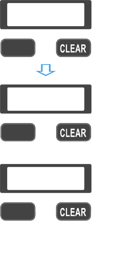
OK
OK
Talk in g
Hanging Up
OK
Disconnected
answered.
5. When call is hang up by receiver, LCD display will show
“Hanging Up”.
6. If called extension number is occupied, the bell sounds a
busy announcement.
7. If there is no one answering this call, the bell sounds
(Ding-Dong) will continuously ring and be discounted
automatically after 15 seconds.(The time out can be set at
Web for 15 ,30 , 45 and 60 seconds).
8. You will see “Disconnected” message on LCD display if
the networking is disconnected.
Answering Calls on IP Video Phone
To answer the call from Video Door Phone on IP Video Phone
is same as normal call. You may answer with following ways:
z Pick up the handset/ Press the 9 button.
z Press the SPEAKER button.
z Press “Answer” soft-function key.
Figure 31: LCD Messages 2
DP100-25 VIDEO DOOR PHONE
43
A
mroad Technolo
gy
Inc.
DP100-25 RFID Card Usage
Residents scan RFID card over the card reader. DP100-25 will verify the database to determine whether to Open door or not.
Issue Master RFID Card First Time
Take the Master RFID Card from package contents to scan on the DP101R RFID reader after the installation of DP101R is
completed. The LCD Display will show the card number of the Master RFID Card. This Master RFID Card will be used as Master
Card1.
NOTE: The Master RFID Card is used for issuing new
card, and it can NOT be used for opening door.
If you scan another RFID card instead of Master RFID
Card on DP100-25 card reader for the first time, the
first-time scanned RFID card will become Master RFID
Card.
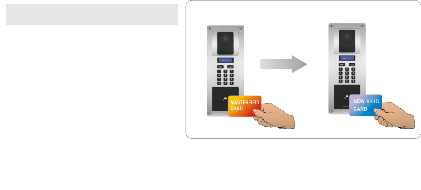
Issue a New Card with Master RFID
Card
1. Scan Master RFID Card on DP100-25 card reader
First.
2. The screen will display “Scan New Card”. Within 10
seconds, scan new RFID card on DP100-25 card reader and LCD
Display will show the card number of the RFID Card. DP100-25
will store new card number into database.
Figure 32: Issue a New RFID Card
DP100-25 SI MANUAL
44
A
mroad Technolo
gy
Inc.
The new RFID card is authorized and can be used to scan over DP100-25 card reader and open door.
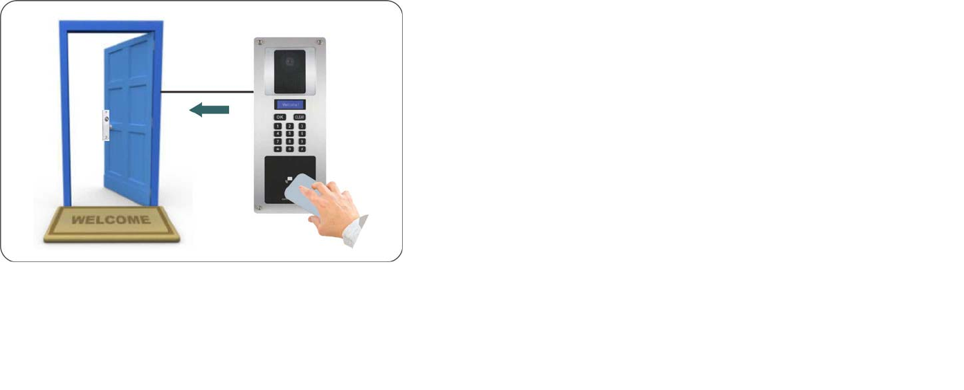
Open the Door
With the installation of electronic lock, residents can open the door through the following 3 ways to open door.
1. Press “#” key on IP Video Phone/Video Indoor Station to open the door.
2. Resident can press indoor “Open Door Button” to open the door.
3. Resident can scan authorized RFID card on DP100-25 card reader to open the door.
Figure 33: Scan RFID card to open door

APPENDIX A: ELECTRONIC LOCK
45
A
mroad Technolo
gy
Inc.
Appendix A : Electronic Lock
Electronic Lock
The DP100-25 can connect with various Electronic locks, including Electronic Strikes, Electronic Bolts and Electromagnetic locks.
There are two types of Electronic door lock applications as below. One is Electronic Bolt, and the other is Electronic Strike. For
more Electronic locks, please follow the similar method for connection.
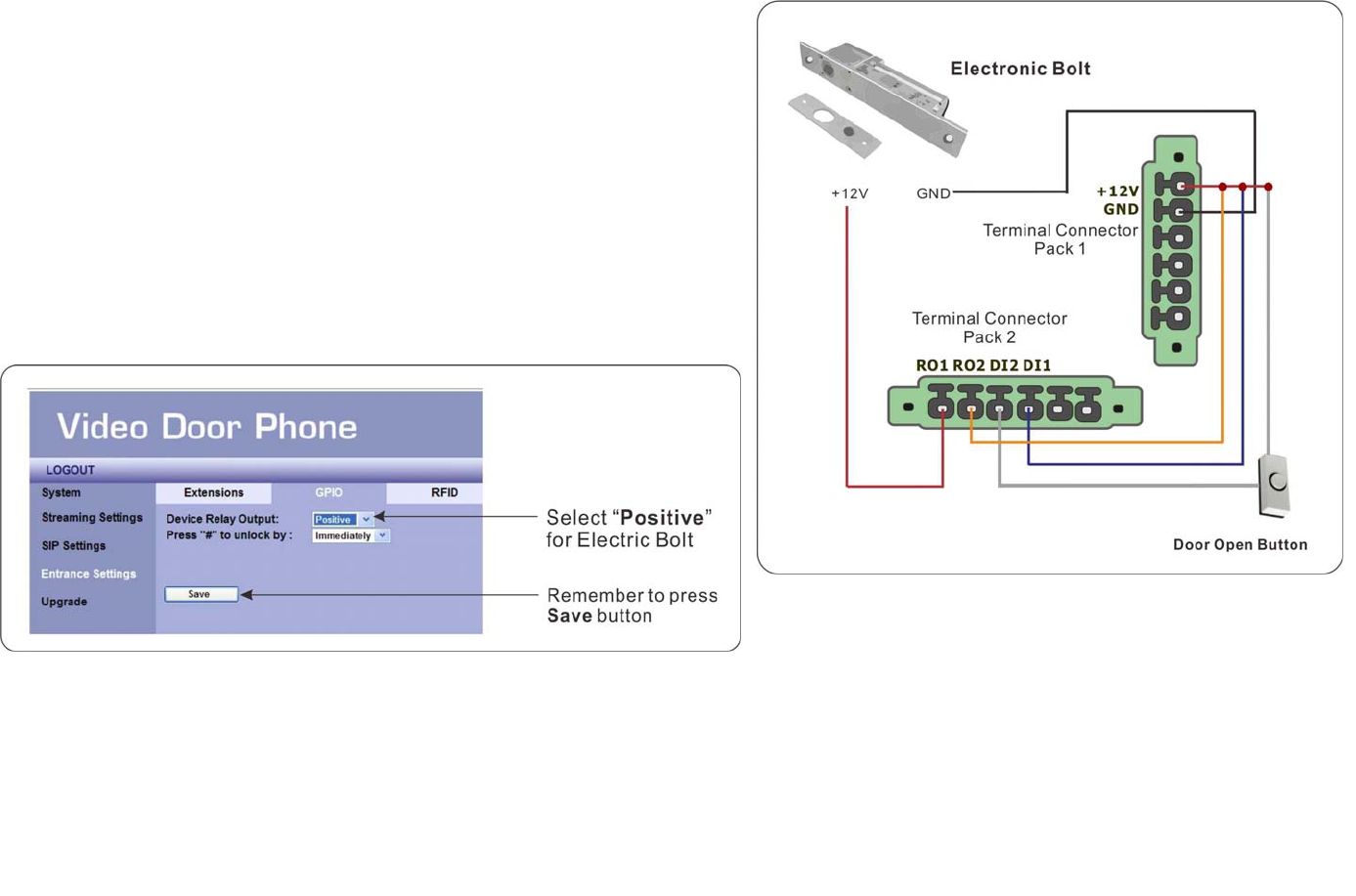
Electronic Bolt
z Electronic Bolt
The Electronic Bolt is closed when +12 V is supplied.
The Electronic Bolt is opened when +12V is not supplied.
This function can let you not only press the pound (#) key to open the door when you are answering Video Door Phone. but
open the door with the Open Door Button directly.
ELECTRONIC LOCK
46
A
mroad Technolo
gy
Inc.
Wiring Connection and Web Page Setup
There are two connectors: Terminal Connector Pack 1 and Terminal
Connector Pack 2 on the rear side of the DP100-25. We provide the
example for wiring connection and web page setup of Electronic
Bolt.
A Door Open Button is connected in the wiring connection.
When the wire connection is completed, you need to select the
“Positive” for Electronic Bolt on the GPIO page of Entrance Setting
on DP100-25 WEB User Interface.
Figure 34: Wiring Connection for Electronic Bolt
Figure 35: Web Page Setup for Electronic Bolt
APPENDIX A: ELECTRONIC LOCK
47
A
mroad Technolo
gy
Inc.
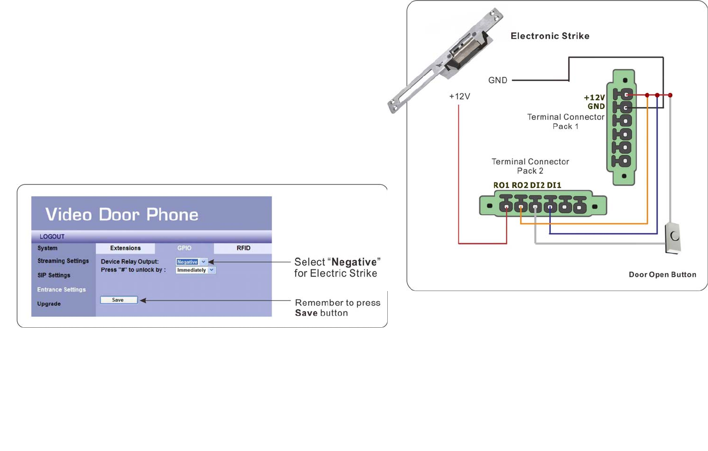
Electronic Strike
z Electronic Strike
The Electronic Strike is opened when +12 V is supplied.
The Electronic Strike is closed when +12V is not supplied.
This function can let you not only press the pound key to open the
door when you are answering Video Door Phone. but open the
door with the Open Door Button directly.
Wiring Connection and Web Page Setup
When the wire connection is completed, we need to select the
“Negative” for Electronic Strike on the GPIO page of Entrance
Setting on DP100-25 WEB User Interface
Figure 37: Web Page Setup for Electronic Strike
Figure 36: Wiring Connection for Electronic Strike

ELECTRONIC LOCK
48
A
mroad Technolo
gy
Inc.
Amroad Technology Inc. 49

REGULATORY INFORMATION
50
A
mroad Technolo
gy
Inc.
CE DECLARATION OF CONFORMITY (EUROPE)
Manufacturer declares that this product conforms to the specifications listed below, following the provisions of the European
R&TTE directive 1999/5/EC:
z EN 301 489-1, 301 489-17 General EMC requirements for Radio equipment
z EN 609 50 Safety
z EN 300-328-1, EN 300-328-2 Technical requirements for Radio equipment
Caution: This equipment is intended to be used in all EU and EFTA countries. Outdoor use may be restricted to certain
frequencies and/or may require a license for operation. Contact local Authority for procedure to follow.
Note: Combinations of power levels and antennas resulting in a radiated power level of above 100 mW equivalent isotropic
radiated power (EIRP) are considered as not compliant with the above mentioned directive and are not allowed for use within the
European community and countries that have adopted the European R&TTE directive 1999/5/EC.

Federal Communication Commission Interference Statement
This equipment has been tested and found to comply with the limits for a Class B digital device, pursuant to Part 15 of the FCC Rules. These
limits are designed to provide reasonable protection against harmful interference in a residential installation.
This equipment generates, uses and can radiate radio frequency energy and, if not installed and used in accordance with the instructions, may
cause harmful interference to radio communications. However, there is no guarantee that interference will not occur in a particular installation. If
this equipment does cause harmful interference to radio or television reception, which can be determined by turning the equipment off and on,
the user is encouraged to try to correct the interference by one of the following measures:
. Reorient or relocate the receiving antenna.
. Increase the separation between the equipment and receiver.
. Connect the equipment into an outlet on a circuit different from that to which the receiver is connected.
. Consult the dealer or an experienced radio/TV technician for help.
FCC Caution: To assure continued compliance, any changes or modifications not expressly approved by the party responsible for compliance
could void the user's authority to operate this equipment. (Example - use only shielded interface cables when connecting to computer or
peripheral devices).
This device complies with Part 15 of the FCC Rules. Operation is subject to the following two conditions:
(1) This device may not cause harmful interference, and (2) This device must accept any interference received, including interference that may
cause undesired operation.