Amcrest Technologies UV-5RV2 Dual Band FM Transceiver User Manual
Amcrest Technologies LLC Dual Band FM Transceiver
UserManual.wiki
>
Amcrest Technologies
>
UV 5RV2 User Manual
User Manual
Navigation menu
Upload a User Manual
Namespaces
Wiki Guide
HTML
PDF
Info
Views
User Manual
Discussion / Help
Navigation

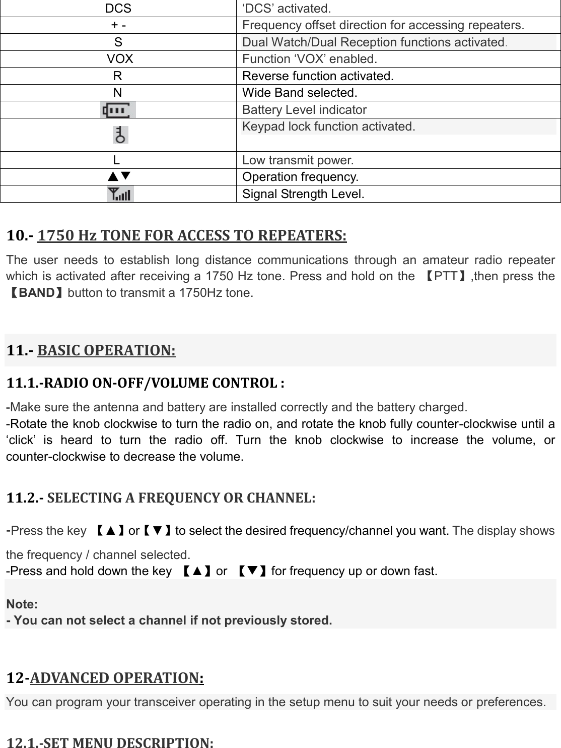
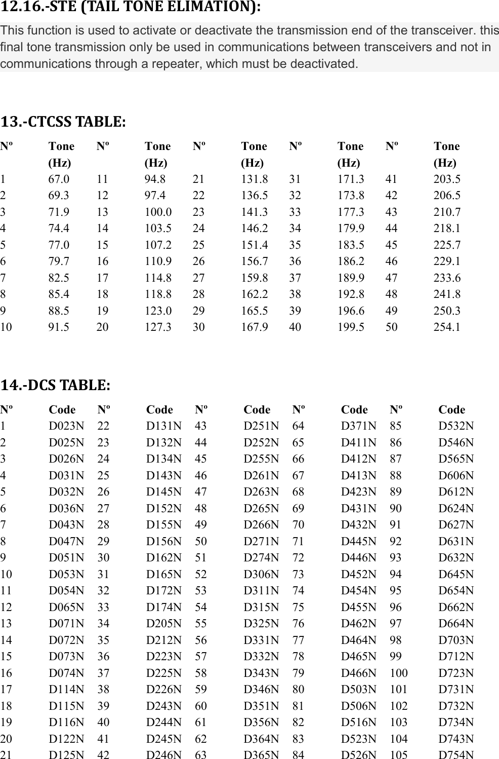
![12.2.-SHORTCUT MENU OPERATION: 1.-Press the key MENU,then press the key ▲ or ▼ to select the desired menu. 2.-Press the key MENU again, come to the parameter setting. 3.-Press the key ▲ or ▼ to select the desired parameter. 4.-Press the key MENU to confirm and save, press the key EXIT to cancel setting or clear the input. -Note: Under channel mode,the following menu settings are invalid:CTCSS,DCS,W/N,PTT-ID,BCL,SCAN ADD TO,S-CODE,CHANNEL NAME.Only the H/L power could be changed. 12.3.-“SQL” (SQUELCH): -The squelch mute the speaker of the transceiver in the absence of reception. With the squelch level correctly set, you will hear sound only while actually receiving signals and significantly reduces battery current consumption. It is recommended that you set Level 5. 12.4.- FUNCTION “VOX” (VOICE OPERATED TRANSMISSION): -This function is not necessary to push the [PTT] on the transceiver for a transmission. Transmission is activated automatically by detecting the radio voice. When finish speaking, the transmission automatically terminated and the transceiver will automatically receive signal. Be sure to adjust the VOX Gain level to an appropriate sensitivity to allow smooth transmission. 12.5.- SELECT WIDEBAND OR NARROW BAND “W/N”: In areas where the RF signals are saturated, you must use the narrow band of transmission to avoid interference in adjacent channels. 12.6.- TDR (DUAL WATCH/DUAL RECEPTION):](https://usermanual.wiki/Amcrest-Technologies/UV-5RV2/User-Guide-4179843-Page-15.png)
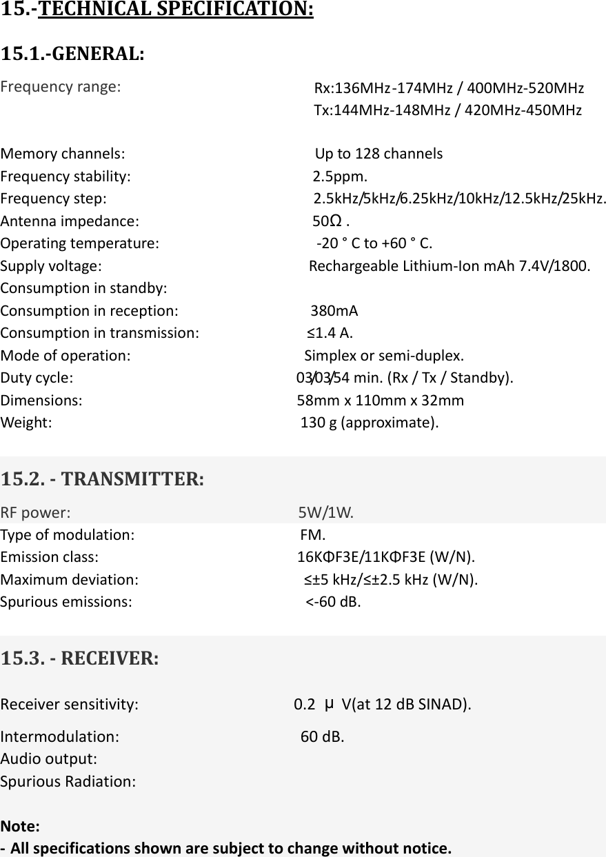
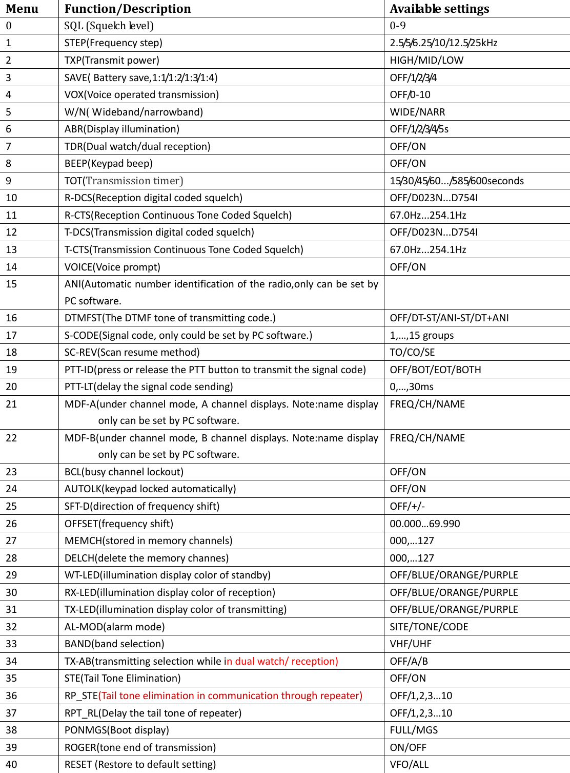
![This feature allows you to operate between frequency A and frequency B. Periodically, the transceiver checks whether a signal is received on another frequency that we have scheduled. If you receive a signal, the unit will remain in the frequency until the received signal disappears. 12.7.- TOT(TRANSMISSION TIMER): This function can automatically control the time we transmit each time you press [PTT] on the transceiver. This feature is very useful to avoid overheating excessive power transistors of the transceiver. The transceiver will be off transmission automatically once the set time. 12.8.-CTCSS/DCS: In some cases only want to establish communications in a closed user group at a particular frequency or channel, for it will use "CTCSS" or code "DCS" for reception. The "squelch" opens only when receiving a frequency with "CTCSS" or codes "DCS" same as the programmed in your transceiver. If codes of the received signal differs from those programmed in your transceiver, the "squelch" will not open and the received signal can be heard. Note: - The use of "CTCSS" or "DCS" in a communication, does not guarantee complete confidentiality communication. 12.9.- ANI -ANI (Automatic Number Identification) is also known as PTT ID because an ID is transmitted when the PTT button of the radio is pressed and/or released. This ID tells the dispatcher which field radio was keyed. 12.10.- DTMFST (DTMF TONE OF TRANSMITTING CODE ): First you should set the PTT-ID as BOT/EOT/BOTH -“OFF”—Under transmitting mode, you can’t hear the DTMF tone, while you press the key to transmit the code or code automatically transmitted. -“DT-ST”—Under transmitting mode, you can hear the DTMF tone, while you press the key to transmit the code. -“ANI-ST”—under transmitting mode, you can hear the DTMF tone, while the code automatically transmitted. -“DT-ANI”—under transmitting mode, you can hear the DTMF tone, while you press the key to transmit the code or the code automatically transmitted.](https://usermanual.wiki/Amcrest-Technologies/UV-5RV2/User-Guide-4179843-Page-16.png)
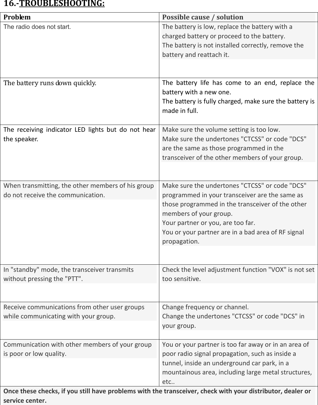
![12.11.- SC-REV(SCAN RESUME METHOD): This transceiver allows you to scan memory channels, all the bands or part of the bands. When the transceiver detects a communication, the scan will stop automatically. Notes: - "TO" (Time Operation): Scanning will stop when it detects an active signal. The scanning will stop on each channel or active frequency for a predetermined time, after that time the scan will resume automatically. - "CO" (Carrier Operation): The scanning will stop and remain in the frequency or channel, until the active signal disappears. - "SE"(Search Operation): The scanning will stop and remain in the frequency or channel after it detects an active signal. 12.12.- PTT-ID(PTT OR RELEASE PTT TO TRANSMIT THE SIGNAL CODE): -This feature allows you to know who call you. -“OFF”—Don’t transmit the code while push the PTT button. -“BOT”-Transmit the code while push the PTT button.(the code only could be set by PC software.) -“EOT”-Transmit the code while release the PTT button. -“BOTH”-Transmit the code while push or release the PTT button. 12.13.- BCL(BUSY CHANNEL LOCKOUT): The BCLO feature prevents the radio’s transmitter from being activated if a signal strong enough to break through the “noise” squelch is present. On a frequency where stations using different CTCSS or DCS codes may be active, BCLO prevents you from disrupting their communications accidentally (because your radio may be muted by its own tone decoder). 12.14.- SFT-D(DIRECTION OF FREQUENCY SHIFT): The "OFFSET" is the difference or offset between the reception frequency and the frequency of transmission for access to amateur radio repeaters. Set the "OFFSET" according to the "OFFSET" amateur radio repeater through which want to communicate. 12.15.- OFFSET(FREQUENCY SHIFT): When communicating via a repeater, the direction of displacement of frequency should be timed to the displacement of the transmission frequency is higher or lower than the receiving frequency. example: If we want to make a communication through amateur radio repeater whose frequency input is 145,000 MHz and 145,600 MHz is output, we select the "OFFSET" of the previous section in 0600 and the direction of travel "SHIFT" programmed to [-], so the transceiver will always 145,600 MHz in frequency and when you press [PTT] to transmit transceiver, the frequency will automatically move to 145,000 MHz](https://usermanual.wiki/Amcrest-Technologies/UV-5RV2/User-Guide-4179843-Page-17.png)