Amcrest Technologies UV-5RV2 Dual Band FM Transceiver User Manual
Amcrest Technologies LLC Dual Band FM Transceiver
User Manual
DUAL BAND FM Transceiver
OPERATING MANUAL
UV-5R V2+
PREFACE
Thank you for purchasing UV-5RV2+ Amateur Portable Radio, which is a dual band/dual display radio.
This easy-to-use radio will deliver you secure, instant and reliable communications at peak
efficiency. Please read this manual carefully before use. The information presented herein will help
you to derive maximum performance from your radio.

CONTENT
1.-SAFETY INFORMATION
2.-FEATURES AND FUNCTIONS
3.-UNPACKING AND CHECKING EQUIPMENTS
4.- OPTIONAL ACCESSORIES
5.- INSTALLATION OF ACCESSORIES
5.1.- INSTALLING THE ANTENNA
5.2.- INSTALLING THE BELT CLIP
5.3.- MICRO-HEADSET INSTALLATION OF EXTERNAL
5.4. – BATTERY INSTALLATION
6.-BATTERY CHARGING
7.-BATTERY INFORMATION
7.1.-INITIAL USE
7.2.-BATTERY TIPS
7.3.-PROLONG BATTERY LIFE
7.4.-BATTERY STORAGE
8.-PARTS, CONTROLS AND KEYS
8.1.-RADIO OVERVIEW
8.2.- COMMAND/KEY DEFINITION
9.-‘LCD’ DISPLAY
10.- 1750 Hz TONE FOR ACCESS TO REPEATERS
11.1.-RADIO ON-OFF/VOLUME CONTROL
11.2.- SELECTING A FREQUENCY OR CHANNEL
12-ADVANCED OPERATION
12.1.-SET MENU DESCRIPTION

12.2.-SHORTCUT MENU OPERATION
12.3.-“SQL” (SQUELCH)
12.4.-FUNCTION “VOX” (VOICE OPERATED TRANSMISSION)
12.5.- SELECT WIDEBAND OR NARROW BAND “W/N”
12.6.-TDR (DUAL WATCH/DUAL RECEPTION)
12.7.- TOT(TRANSMISSION TIMER)
12.8.-CTCSS/DCS
12.9.- ANI
12.10.- DTMFST (DTMF TONE OF TRANSMITTING CODE )
12.11.- SC-REV(SCAN RESUME METHOD)
12.12.- PTT-ID(PTT OR RELEASE PTT TO TRANSMIT THE SIGNAL CODE)
12.13-BCL(BUSY CHANNEL LOCKOUT)
12.14.- SFT-D(DIRECTION OF FREQUENCY SHIFT)
12.15.- OFFSET(FREQUENCY SHIFT)
12.16.-STE(STE TAIL TONE ELIMATION)
13.-CTCSS TABLE
14.-DCS TABLE
15.-TECHNICAL SPECIFICATION
15.1.-GENERAL
15.2. – TRANSMITTER
15.3. - RECEIVER
16.-TROUBLESHOOTING
17.-WARRANTY

1.-SAFETY INFORMATION:
The following safety precautions shall always be observed during operation, service and repair of this equipment.
◇ This equipment shall be serviced by qualified technicians only.
◇ Do not modify the radio for any reason.
◇ Use only BAOFENG supplied or approved batteries and chargers.
◇ Do not use any portable radio that has a damaged antenna. If a damaged antenna comes into contact with
your skin, a minor burn can result.
◇ Turn off your radio prior to entering any area with explosive and flammable materials.
◇ Do not charge your battery in a location with explosive and flammable materials.
◇ To avoid electromagnetic interference and/or compatibility conflicts, turn off your radio in any area where
posted notices instruct you to do so.
◇ Turn off your radio before boarding an aircraft. Any use of a radio must be in accordance with airline
regulations or crew instructions.
◇ Turn off your radio before entering a blasting area.
◇ For vehicles with an air bag, do not place a radio in the area over an air bag or in the air bag deployment area.
◇ Do not expose the radio to direct sunlight over a long time, nor place it close to heating source.
◇ When transmitting with a portable radio, hold the radio in a vertical position with the microphone 3 to 4
centimeters away from your lips. Keep antenna at least 2.5 centimeters away from your body when transmitting.
WARNING: If you wear a radio on your body, ensure the radio and its antenna are at least 2.5
centimeters away from your body when transmitting.
2.-FEATURES AND FUNCTIONS:
-Dual-band handheld transceiver with display function menu on the display "LCD".
- DTMF encoded.
- Commercial FM radio receiver (65 MHz ~ 108 MHz).
- Incorporates 105 codes "DCS" and 50 privacy codes "CTCSS" programmable.
- Function "VOX" (voice operated transmission).
- Alarm function.
- Up to 128 memory channels.
- Broadband (Wide) / Narrowband (Narrow), selectable.
- High power / low ( 5 W/1 W) selectable.
- Display illumination and programmable keyboard.
- Function "beep" on the keyboard.
- Dual Watch/dual reception .
- Selectable Frequency Step 2.5/5/6.25/10/12.5/25 kHz.
- Function "OFFSET" (frequency offset for repeater access).
- Battery saving function "SAVE".
- Timer transmission "TOT" programmable.
- Selecting the Scan Mode.
- Function Busy Channel Lock "BCLO".
- Built-in RX CTCSS/DCS scan
- Built-in LED flashlight.
- Programmable by PC.
- Level Threshold "Squelch" adjustable from 0 to 9.
-Crossband reception/transmission
-Tone end of transmission
- Built-in key lock
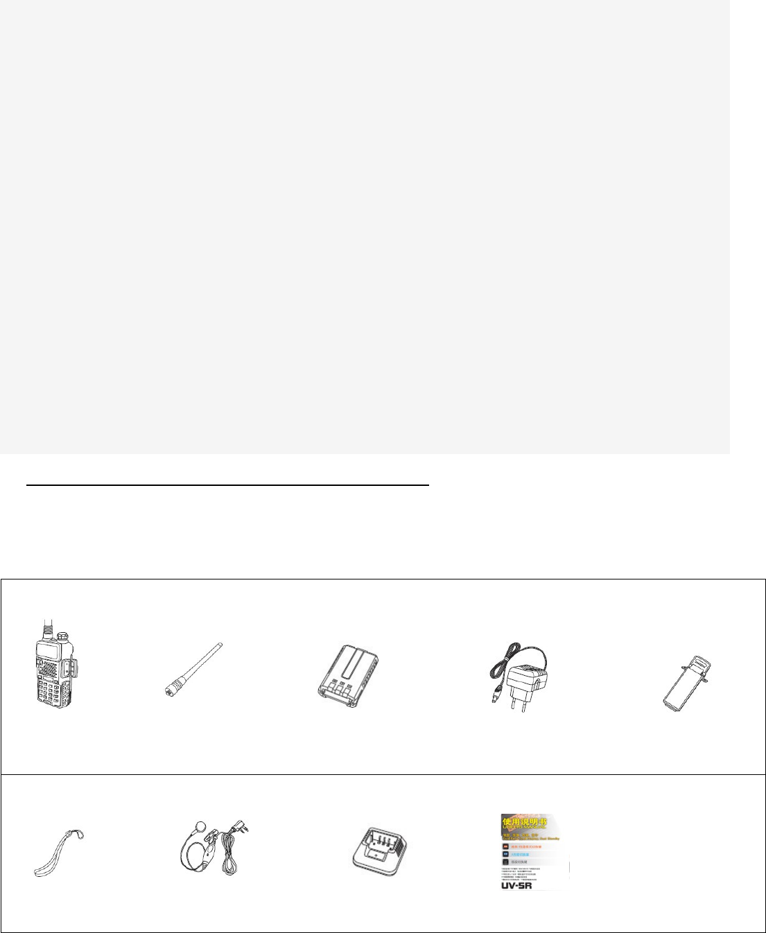
3.-UNPACKING AND CHECKING EQUIPMENTS:
Carefully unpack the transceiver. We recommend that you identify the items listed in the following
before discarding the packing material. If any items are missing or have been damaged during
shipment, please contact your dealers immediately.
Note:
- Items included in the package, may differ from those listed in the table above depending
on the country of purchase. For more information, consult your dealer or vendor.
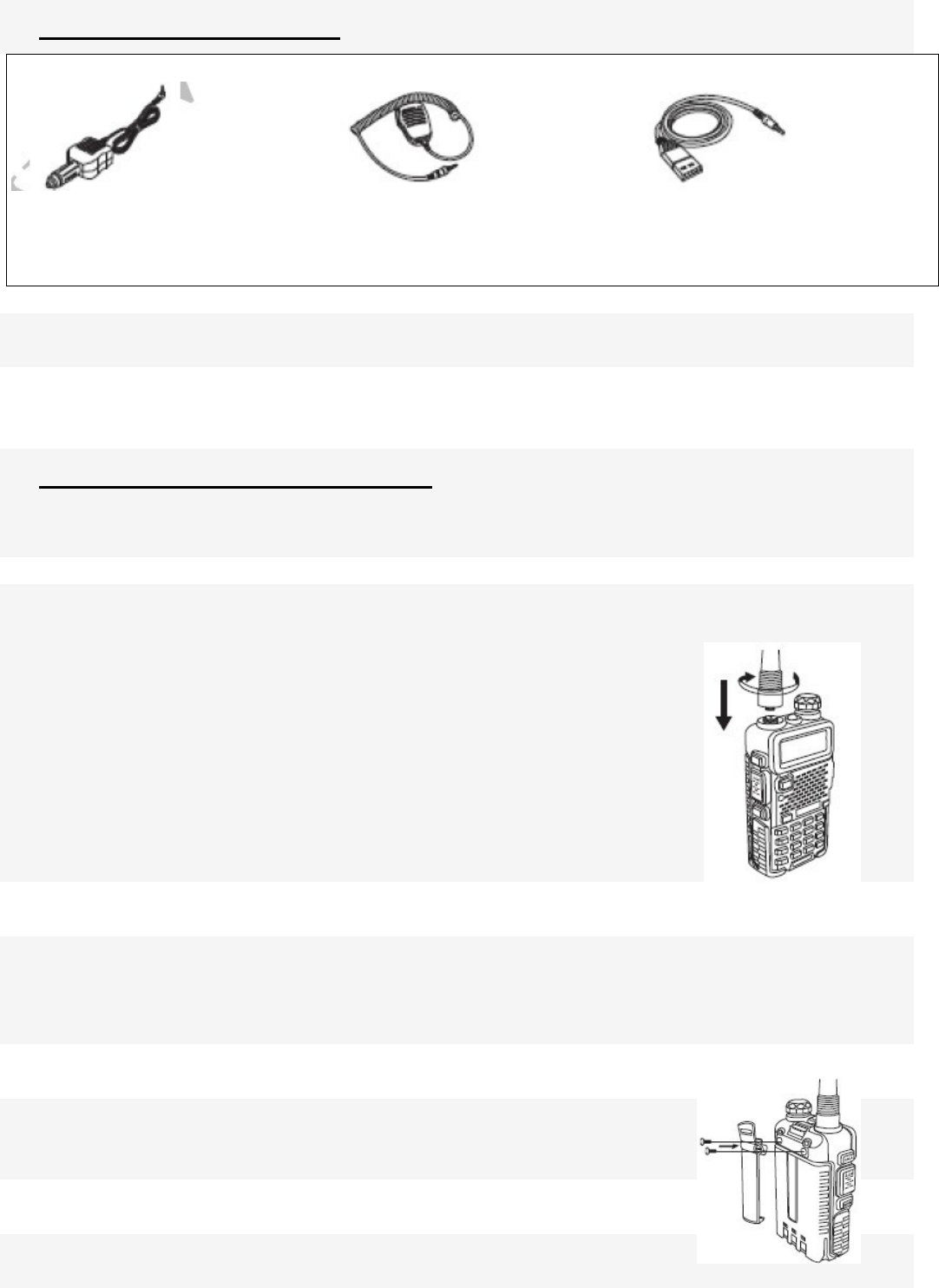
4.- OPTIONAL ACCESSORIES:
Note:
- Consult the dealer or retailer for information about options available.
5.- INSTALLATION OF ACCESSORIES:
5.1.- INSTALLING THE ANTENNA:
Install the antenna as shown in the figure below and turn it clockwise until it stops.
Note:
- When installing the antenna, don’t rotate it by its top,
holding it by its base and turn.
- If you use an external antenna, make sure the ‘SWR’ is
about 1.5:1 or less, to avoid damage to the transceiver's
final transistors.
- Do not hold the antenna with your hand or wrap the outside
of it to avoid bad operation of the transceiver.
- Never transmit without an antenna.
5.2.- INSTALLING THE BELT CLIP:
If necessary, install the belt clip at the rear of the battery compartment cover as
shown in the figure below.
Note:
- Do not use any kind of glue to fix the screw on the belt clip.
The solvents Glue may damage the battery casing.
5.3.- MICRO-HEADSET INSTALLATION OF EXTERNAL:
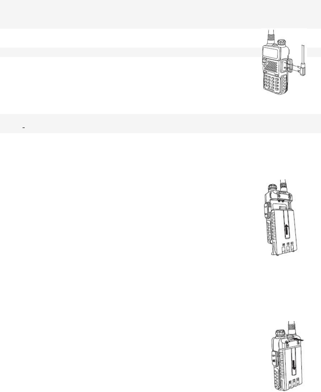
Plug the external micro-headset connector into the jack of ‘SP. & MIC’
of the transceiver as shown in the figure below.
5.4. – BATTERY INSTALLATION:
-When attaching the battery, make sure the battery is in parallel and in good contact with the
aluminum chassis. The battery bottom is about 1 to 2 centimeters below the bottom of the radio’s
body.
-Align the battery with the guide rails on the aluminum chassis and slide it upwards until a ‘click’ is
heard.
-The battery latch at the bottom locks the battery.
-Turn off the radio before removing the battery.
-Slide the battery latch, at the bottom of the radio’s body, in the direction indicated by the arrow.
-Slide down the battery for about 1 to 2 centimeters, and then remove the battery from the radio’s
body.
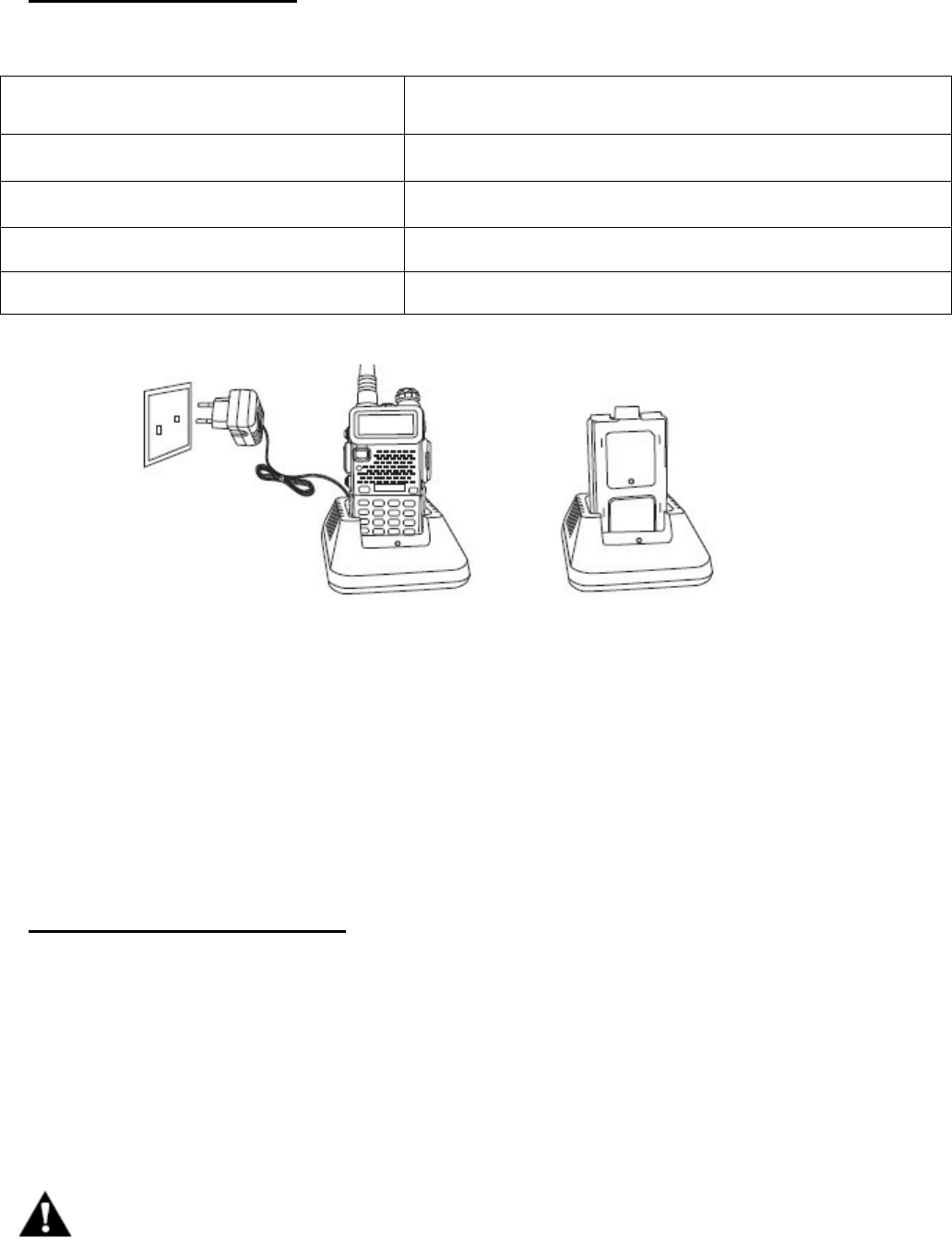
6.-BATTERY CHARGING:
Use only the charger specified by the manufacturer. The charger’s LED indicates the charging
progress.
CHARGING STATUS LED INDICATION
Standby (no-load) Red LED flashes,while Green LED glows
Charging Red LED solidly glows
Fully Charged Green LED solidly glows
Error Red LED flashes,while Green LED glows
Please follow these steps:
1. Plug the power cord into the adapter.
2. Plug the AC connector of the adapter into the AC outlet socket.
3. Plug the DC connector of the adapter into the DC socket on the back of the charger.
4. Place the radio with the battery attached, or the battery alone, in the charger.
5. Make sure the battery is in good contact with the charging terminals. The charging process
initiates when the red LED lights.
6. The green LED lights about 4 hours later indicating the battery is fully charged. Then remove the
radio with the battery attached or the battery alone from the charger.
7.-BATTERY INFORMATION:
7.1.-INITIAL USE
New batteries are shipped uncharged fully from the factory. Charge a new battery for 5 hours
before initial use. The maximum battery capacity and performance is achieved after three full
charge/discharge cycles. If you notice the battery power runs low, please recharge the battery.
WARNING: -To reduce the risk of injury, charge only the battery specified by the manufacturer. Other batteries may
burst, causing bodily injury and property damage.
-To avoid risk of personal injury, do not dispose of batteries in a fire!
-Dispose of batteries according to local regulations (e.g. recycling). Do not dispose as household waste.
-Never attempt to disassemble the battery.
7.2.-BATTERY TIPS:
1. When charging your battery, keep it at a temperature among 5℃ - 40℃. Temperature out of the
limit may cause battery leakage or damage.
2. When charging a battery attached to a radio, turn the radio off to ensure a full charge.
3. Do not cut off the power supply or remove the battery when charging a battery.
4. Never charge a battery that is wet. Please dry it with a soft cloth prior to charge.
5. The battery will eventually wear out. When the operating time (talk-time and standby time) is
noticeably shorter than normal performance, it is time to buy a new battery.
7.3.-PROLONG BATTERY LIFE:
1. Battery performance will be greatly decreased at a temperature below 0℃. A spare battery is
necessary in cold weather. The cold battery unable to work in this situation may work under room
temperature, so keep it for later use.
2. The dust on the battery contact may cause the battery cannot work or charge. Please use a
clean dry cloth to wipe it before attaching the battery to the radio.
7.4.-BATTERY STORAGE:
1. Fully charge a battery before you store it for a long time, to avoid battery damage due to
over-discharge.
2. Recharge a battery after several months’ storage (Li-Ion batteries: 6 months), to avoid battery
capacity reduction due to over-discharge.
3. Store your battery in a cool and dry place under room temperature, to reduce self-discharge.
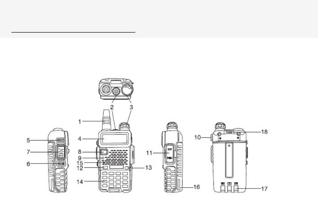
8.-PARTS, CONTROLS AND KEYS:
8.1.-RADIO OVERVIEW:

① antenna 11.accessory jack
② flashlight 12.A/B key(frequency display switches)
3. knob (ON/OFF,volume) 13.BAND key(band switches)
4.LCD 14.keypad
5.SK-side key1/CALL(radio,alarm) 15.SP.&MIC.
6.SK-side key2/MONI(flashlight,monitor) 16.battery pack
7. PTT key(push-to-talk) 17.battery contacts
8.VFO/MR (frequency mode/channel mode) 18.battery remove button
9.LED indicator
10.strap buckle
8.2.- COMMAND/KEY DEFINITION:
-【PTT】(PUSH-TO-TALK):
Press and hold down the 【PTT】 button to transmit; release it to receive.
- SK-SIDE KEY1/【CALL】:
-Press the 【CALL】button,to activate the FM Radio;Press it again to deactivate the FM Radio.
-Press and hold on the 【CALL】button,to activate the alarm function; Press and hold it again,to
deactivate the alarm function.
- SK-SIDE KEY2/【MONI】:
-Press the 【MONI】button,to turn on the flashlight;Press it again to turn off.Press and hold on the
【MONI】 button,to monitor the signal.
-【VFO/MR】BUTTON:
-Press the 【VFO/MR】button,to switch the frequency mode and channel mode.
-【A/B】BUTTON:
-Press the 【A/B】button,to switch frequency display.
-【BAND】BUTTON:
-Press the 【BAND】button,to switch band dispaly.
-While FM radio being activated,press the 【BAND】button to switch the band of FM radio(band
65-75MHz/76-108MHz).
-【*SCAN】KEY:
-Press the 【*SCAN】key to activate the Reverse function,it will exchange a separate reception and
transmission frequency.
-Press the 【*SCAN】key for 2 seconds to start scanning(frequency/channel).
- While FM radio being activated,press the 【*SCAN】key to search FM radio station.
-While setting the RX CTCSS/DCS, press the key 【*SCAN】to scan the RX CTCSS/DCS.
- KEY:
-Under channel mode, press key to switch High/Low transmit power.
-Press key for 2 seconds to lock/unlock the keypad.
-FUNCTION KEYPAD:
-【MENU】key:
-To enter the menu of the radio and confirm the setting.
-【▲】【▼】key:
-Press and hold 【▲】or 【▼】key for frequency up or down fast.
-Press 【▲】or 【▼】key,the scanning will be opposite.
-【EXIT】key:
-To cancel /clear or exit.
-NUMERIC KEYPAD:
-Used to enter information for programming the radio’s lists and the non-standard CTCSS
-Under transmission mode, press the numeric key to send the signal code
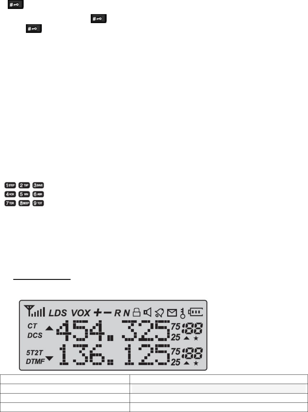
9.-‘LCD’ DISPLAY:
The display icons appear when certain operations or specific features are activated.
Icon Description
188 Operating channel.
75/25
CT ‘CTCSS’ activated.

DCS ‘DCS’ activated.
+ - Frequency offset direction for accessing repeaters.
S Dual Watch/Dual Reception functions activated.
VOX Function ‘VOX’ enabled.
R Reverse function activated.
N Wide Band selected.
Battery Level indicator
Keypad lock function activated.
L Low transmit power.
▲▼ Operation frequency.
Signal Strength Level.
10.- 1750 Hz TONE FOR ACCESS TO REPEATERS:
The user needs to establish long distance communications through an amateur radio repeater
which is activated after receiving a 1750 Hz tone. Press and hold on the 【PTT】,then press the
【BAND】button to transmit a 1750Hz tone.
11.- BASIC OPERATION:
11.1.-RADIO ON-OFF/VOLUME CONTROL :
-Make sure the antenna and battery are installed correctly and the battery charged.
-Rotate the knob clockwise to turn the radio on, and rotate the knob fully counter-clockwise until a
‘click’ is heard to turn the radio off. Turn the knob clockwise to increase the volume, or
counter-clockwise to decrease the volume.
11.2.- SELECTING A FREQUENCY OR CHANNEL:
-Press the key 【▲】or【▼】to select the desired frequency/channel you want. The display shows
the frequency / channel selected.
-Press and hold down the key 【▲】or 【▼】for frequency up or down fast.
Note:
- You can not select a channel if not previously stored.
12-ADVANCED OPERATION:
You can program your transceiver operating in the setup menu to suit your needs or preferences.
12.1.-SET MENU DESCRIPTION:

Menu Function/Description Available settings
0 SQL (Squelch level) 0-9
1 STEP(Frequency step) 2.5/5/6.25/10/12.5/25kHz
2 TXP(Transmit power) HIGH/MID/LOW
3 SAVE( Battery save,1:1/1:2/1:3/1:4) OFF/1/2/3/4
4 VOX(Voice operated transmission) OFF/0-10
5 W/N( Wideband/narrowband) WIDE/NARR
6 ABR(Display illumination) OFF/1/2/3/4/5s
7 TDR(Dual watch/dual reception) OFF/ON
8 BEEP(Keypad beep) OFF/ON
9 TOT(Transmission timer) 15/30/45/60.../585/600seconds
10 R-DCS(Reception digital coded squelch) OFF/D023N...D754I
11 R-CTS(Reception Continuous Tone Coded Squelch) 67.0Hz...254.1Hz
12 T-DCS(Transmission digital coded squelch) OFF/D023N...D754I
13 T-CTS(Transmission Continuous Tone Coded Squelch) 67.0Hz...254.1Hz
14 VOICE(Voice prompt) OFF/ON
15 ANI(Automatic number identification of the radio,only can be set by
PC software.
16 DTMFST(The DTMF tone of transmitting code.) OFF/DT-ST/ANI-ST/DT+ANI
17 S-CODE(Signal code, only could be set by PC software.) 1,…,15 groups
18 SC-REV(Scan resume method) TO/CO/SE
19 PTT-ID(press or release the PTT button to transmit the signal code) OFF/BOT/EOT/BOTH
20 PTT-LT(delay the signal code sending) 0,…,30ms
21 MDF-A(under channel mode, A channel displays. Note:name display
only can be set by PC software.
FREQ/CH/NAME
22 MDF-B(under channel mode, B channel displays. Note:name display
only can be set by PC software.
FREQ/CH/NAME
23 BCL(busy channel lockout) OFF/ON
24 AUTOLK(keypad locked automatically) OFF/ON
25 SFT-D(direction of frequency shift) OFF/+/-
26 OFFSET(frequency shift) 00.000…69.990
27 MEMCH(stored in memory channels) 000,…127
28 DELCH(delete the memory channes) 000,…127
29 WT-LED(illumination display color of standby) OFF/BLUE/ORANGE/PURPLE
30 RX-LED(illumination display color of reception) OFF/BLUE/ORANGE/PURPLE
31 TX-LED(illumination display color of transmitting) OFF/BLUE/ORANGE/PURPLE
32 AL-MOD(alarm mode) SITE/TONE/CODE
33 BAND(band selection) VHF/UHF
34 TX-AB(transmitting selection while in dual watch/ reception) OFF/A/B
35 STE(Tail Tone Elimination) OFF/ON
36 RP_STE(Tail tone elimination in communication through repeater) OFF/1,2,3…10
37 RPT_RL(Delay the tail tone of repeater) OFF/1,2,3…10
38 PONMGS(Boot display) FULL/MGS
39 ROGER(tone end of transmission) ON/OFF
40 RESET (Restore to default setting) VFO/ALL
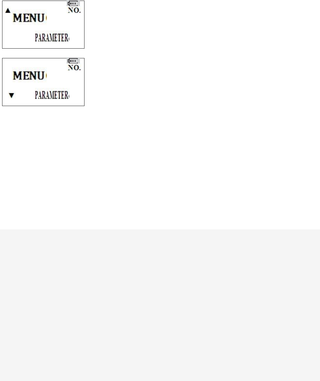
12.2.-SHORTCUT MENU OPERATION:
1.-Press the key MENU,then press the key ▲ or ▼ to select the desired menu.
2.-Press the key MENU again, come to the parameter setting.
3.-Press the key ▲ or ▼ to select the desired parameter.
4.-Press the key MENU to confirm and save, press the key EXIT to cancel setting or clear the input.
-Note:
Under channel mode,the following menu settings are invalid:CTCSS,DCS,W/N,PTT-ID,BCL,SCAN ADD
TO,S-CODE,CHANNEL NAME.Only the H/L power could be changed.
12.3.-“SQL” (SQUELCH):
-The squelch mute the speaker of the transceiver in the absence of reception. With the squelch level
correctly set, you will hear sound only while actually receiving signals and significantly reduces battery
current consumption. It is recommended that you set Level 5.
12.4.- FUNCTION “VOX” (VOICE OPERATED TRANSMISSION):
-This function is not necessary to push the [PTT] on the transceiver for a transmission. Transmission is
activated automatically by detecting the radio voice. When finish speaking, the transmission automatically
terminated and the transceiver will automatically receive signal. Be sure to adjust the VOX Gain level to an
appropriate sensitivity to allow smooth transmission.
12.5.- SELECT WIDEBAND OR NARROW BAND “W/N”:
In areas where the RF signals are saturated, you must use the narrow band of transmission to avoid
interference in adjacent channels.
12.6.- TDR (DUAL WATCH/DUAL RECEPTION):

This feature allows you to operate between frequency A and frequency B. Periodically, the
transceiver checks whether a signal is received on another frequency that we have scheduled. If
you receive a signal, the unit will remain in the frequency until the received signal disappears.
12.7.- TOT(TRANSMISSION TIMER):
This function can automatically control the time we transmit each time you press [PTT] on the transceiver. This
feature is very useful to avoid overheating excessive power transistors of the transceiver. The transceiver will be
off transmission automatically once the set time.
12.8.-CTCSS/DCS:
In some cases only want to establish communications in a closed user group at a particular frequency or
channel, for it will use "CTCSS" or code "DCS" for reception.
The "squelch" opens only when receiving a frequency with "CTCSS" or codes "DCS" same as the
programmed in your transceiver. If codes of the received signal differs from those programmed in your
transceiver, the "squelch" will not open and the received signal can be heard.
Note:
- The use of "CTCSS" or "DCS" in a communication, does not guarantee complete confidentiality
communication.
12.9.- ANI
-ANI (Automatic Number Identification) is also known as PTT ID because an ID is transmitted when the PTT
button of the radio is pressed and/or released. This ID tells the dispatcher which field radio was keyed.
12.10.- DTMFST (DTMF TONE OF TRANSMITTING CODE ):
First you should set the PTT-ID as BOT/EOT/BOTH
-“OFF”—Under transmitting mode, you can’t hear the DTMF tone, while you press the key to transmit
the code or code automatically transmitted.
-“DT-ST”—Under transmitting mode, you can hear the DTMF tone, while you press the key to transmit
the code.
-“ANI-ST”—under transmitting mode, you can hear the DTMF tone, while the code automatically
transmitted.
-“DT-ANI”—under transmitting mode, you can hear the DTMF tone, while you press the key to transmit
the code or the code automatically transmitted.

12.11.- SC-REV(SCAN RESUME METHOD):
This transceiver allows you to scan memory channels, all the bands or part of the bands.
When the transceiver detects a communication, the scan will stop automatically.
Notes:
- "TO" (Time Operation):
Scanning will stop when it detects an active signal. The scanning will stop on each channel or
active frequency for a predetermined time, after that time the scan will resume automatically.
- "CO" (Carrier Operation):
The scanning will stop and remain in the frequency or channel, until the active signal disappears.
- "SE"(Search Operation):
The scanning will stop and remain in the frequency or channel after it detects an active signal.
12.12.- PTT-ID(PTT OR RELEASE PTT TO TRANSMIT THE SIGNAL CODE):
-This feature allows you to know who call you.
-“OFF”—Don’t transmit the code while push the PTT button.
-“BOT”-Transmit the code while push the PTT button.(the code only could be set by PC software.)
-“EOT”-Transmit the code while release the PTT button.
-“BOTH”-Transmit the code while push or release the PTT button.
12.13.- BCL(BUSY CHANNEL LOCKOUT):
The BCLO feature prevents the radio’s transmitter from being activated if a signal strong enough to break
through the “noise” squelch is present. On a frequency where stations using different CTCSS or DCS codes
may be active, BCLO prevents you from disrupting their communications accidentally (because your radio
may be muted by its own tone decoder).
12.14.- SFT-D(DIRECTION OF FREQUENCY SHIFT):
The "OFFSET" is the difference or offset between the reception frequency and the frequency of
transmission for access to amateur radio repeaters. Set the "OFFSET" according to
the "OFFSET" amateur radio repeater through which want to communicate.
12.15.- OFFSET(FREQUENCY SHIFT):
When communicating via a repeater, the direction of displacement of
frequency should be timed to the displacement of the transmission frequency is
higher or lower than the receiving frequency.
example:
If we want to make a communication through amateur radio repeater whose frequency
input is 145,000 MHz and 145,600 MHz is output, we select the
"OFFSET" of the previous section in 0600 and the direction of travel "SHIFT" programmed
to [-], so the transceiver will always 145,600 MHz in frequency and when
you press [PTT] to transmit transceiver, the frequency will automatically move to
145,000 MHz

12.16.-STE (TAIL TONE ELIMATION):
This function is used to activate or deactivate the transmission end of the transceiver. this
final tone transmission only be used in communications between transceivers and not in
communications through a repeater, which must be deactivated.
13.-CTCSS TABLE:
Nº Tone
(Hz)
Nº Tone
(Hz)
Nº Tone
(Hz)
Nº Tone
(Hz)
Nº Tone
(Hz)
1 67.0 11 94.8 21 131.8 31 171.3 41 203.5
2 69.3 12 97.4 22 136.5 32 173.8 42 206.5
3 71.9 13 100.0 23 141.3 33 177.3 43 210.7
4 74.4 14 103.5 24 146.2 34 179.9 44 218.1
5 77.0 15 107.2 25 151.4 35 183.5 45 225.7
6 79.7 16 110.9 26 156.7 36 186.2 46 229.1
7 82.5 17 114.8 27 159.8 37 189.9 47 233.6
8 85.4 18 118.8 28 162.2 38 192.8 48 241.8
9 88.5 19 123.0 29 165.5 39 196.6 49 250.3
10 91.5 20 127.3 30 167.9 40 199.5 50 254.1
14.-DCS TABLE:
Nº Code Nº Code Nº Code Nº Code Nº Code
1 D023N 22 D131N 43 D251N 64 D371N 85 D532N
2 D025N 23 D132N 44 D252N 65 D411N 86 D546N
3 D026N 24 D134N 45 D255N 66 D412N 87 D565N
4 D031N 25 D143N 46 D261N 67 D413N 88 D606N
5 D032N 26 D145N 47 D263N 68 D423N 89 D612N
6 D036N 27 D152N 48 D265N 69 D431N 90 D624N
7 D043N 28 D155N 49 D266N 70 D432N 91 D627N
8 D047N 29 D156N 50 D271N 71 D445N 92 D631N
9 D051N 30 D162N 51 D274N 72 D446N 93 D632N
10 D053N 31 D165N 52 D306N 73 D452N 94 D645N
11 D054N 32 D172N 53 D311N 74 D454N 95 D654N
12 D065N 33 D174N 54 D315N 75 D455N 96 D662N
13 D071N 34 D205N 55 D325N 76 D462N 97 D664N
14 D072N 35 D212N 56 D331N 77 D464N 98 D703N
15 D073N 36 D223N 57 D332N 78 D465N 99 D712N
16 D074N 37 D225N 58 D343N 79 D466N 100 D723N
17 D114N 38 D226N 59 D346N 80 D503N 101 D731N
18 D115N 39 D243N 60 D351N 81 D506N 102 D732N
19 D116N 40 D244N 61 D356N 82 D516N 103 D734N
20 D122N 41 D245N 62 D364N 83 D523N 104 D743N
21 D125N 42 D246N 63 D365N 84 D526N 105 D754N

15.-TECHNICAL SPECIFICATION:
15.1.-GENERAL:
Frequency range:
Rx:136MHz-174MHz / 400MHz-520MHz
Tx:144MHz-148MHz / 420MHz-450MHz
Memory channels: Up to 128 channels
Frequency stability: 2.5ppm.
Frequency step: 2.5kHz/5kHz/6.25kHz/10kHz/12.5kHz/25kHz.
Antenna impedance: 50Ω.
Operating temperature: -20 ° C to +60 ° C.
Supply voltage: Rechargeable Lithium-Ion mAh 7.4V/1800.
Consumption in standby:
Consumption in reception: 380mA
Consumption in transmission: ≤1.4 A.
Mode of operation: Simplex or semi-duplex.
Duty cycle: 03/03/54 min. (Rx / Tx / Standby).
Dimensions: 58mm x 110mm x 32mm
Weight: 130 g (approximate).
15.2. - TRANSMITTER:
RF power: 5W/1W.
Type of modulation: FM.
Emission class: 16KΦF3E/11KΦF3E (W/N).
Maximum deviation: ≤±5 kHz/≤±2.5 kHz (W/N).
Spurious emissions: <-60 dB.
15.3. - RECEIVER:
Receiver sensitivity: 0.2 μV(at 12 dB SINAD).
Intermodulation: 60 dB.
Audio output:
Spurious Radiation:
Note:
- All specifications shown are subject to change without notice.

16.-TROUBLESHOOTING:
Problem Possible cause / solution
The radio does not start. The battery is low, replace the battery with a
charged battery or proceed to the battery.
The battery is not installed correctly, remove the
battery and reattach it.
The battery runs down quickly. The battery life has come to an end, replace the
battery with a new one.
The battery is fully charged, make sure the battery is
made in full.
The receiving indicator LED lights but do not hear
the speaker.
Make sure the volume setting is too low.
Make sure the undertones "CTCSS" or code "DCS"
are the same as those programmed in the
transceiver of the other members of your group.
When transmitting, the other members of his group
do not receive the communication.
Make sure the undertones "CTCSS" or code "DCS"
programmed in your transceiver are the same as
those programmed in the transceiver of the other
members of your group.
Your partner or you, are too far.
You or your partner are in a bad area of RF signal
propagation.
In "standby" mode, the transceiver transmits
without pressing the "PTT".
Check the level adjustment function "VOX" is not set
too sensitive.
Receive communications from other user groups
while communicating with your group.
Change frequency or channel.
Change the undertones "CTCSS" or code "DCS" in
your group.
Communication with other members of your group
is poor or low quality.
You or your partner is too far away or in an area of
poor radio signal propagation, such as inside a
tunnel, inside an underground car park, in a
mountainous area, including large metal structures,
etc..
Once these checks, if you still have problems with the transceiver, check with your distributor, dealer or
service center.

17.-WARRANTY: (Better buy the radios from local dealer).
WARRANTY CERTIFICATE
Brand: Model no.: Serial no.:
Name of purchaser:
Address:
Seal and name of the dealer:
City: Zip code:
Province/State: Tel no.:
Date of purchase:
WARNING: Warranty is valid provided it is complete and properly
filled in legibly and clearly present the seal and name of the dealer
and have attached the bill proof of purchase of equipment.
The device described in this Certificate is guaranteed for a period of TWO YEARS from the date of sale to the
final user.This Warranty Certificate is unique and not transferable and may not be reissued for new or original
or copy. Substitution of product failure or any part thereof shall not involve extension of the guarantee.
The warranty covers the replacement and free replacement of all parts that are defective in materials and
components used in manufacturing and / or assembly of the apparatus.

The warranty does not cover any faults caused by accident, improper installation and use, electric shock (eg
storms), connect a power other than that specified, reverse polarity in the diet, or claims due to deterioration in
the external appearance of normal use, nor the amount or condition of the accessories.
Checking the accessories is the responsibility of the purchaser at the time of purchasing the device.
The warranty does not cover rechargeable batteries even if they are part of the equipment purchased as they are
considered consumables, the impairment must be reported within a period of fifteen days from the date of
purchase.
The warranty is void on the following assumptions:
1. - Devices that have been manipulated by another or by anyone other than authorized service provider.
2. - Equipment and accessories in which the serial number has been altered, deleted or filed unreadable.
3. - Use of the product than as intended.
To make use of the guarantee is necessary to give the dealer or any of the Authorised Service the defective
device with its accessories and the following documentation:
1. - Warranty Certificate duly completed and sealed.
2. - Original invoice which clearly identifies the device and the date of purchase.
3. - Description of the faults.
The warranty terms contained in this Certificate of Guarantee do not exclude, modify or restrict the statutory
rights of the buyer by virtue of the laws in force at the time of purchase, but are added to them.
NOTE: This equipment has been tested and found to comply with the limits for a
Class B digital device, pursuant to part 15 of the FCC Rules. These limits are
designed to provide reasonable protection against harmful interference in a
residential installation. This equipment generates uses and can radiate radio
frequency energy and, if not installed and used in accordance with the instructions,
may cause harmful interference to radio communications. However, there is no
guarantee that interference will not occur in a particular installation. If this
equipment does cause harmful interference to radio or television reception, which
can be determined by turning the equipment off and on, the user is encouraged to
try to correct the interference by one or more of the following measures:
- Reorient or relocate the receiving antenna.
- Increase the separation between the equipment and receiver.
-Connect the equipment into an outlet on a circuit different from that to which the
receiver is connected.
-Consult the dealer or an experienced radio/TV technician for help
Changes or modifications not expressly approved by the party responsible for compliance
could void the user's authority to operate the equipment. This device complies with Part
15 of the FCC Rules. Operation is subject to the following two conditions:
(1) this device may not cause harmful interference, and
(2) this device must accept any interference received, including interference that may
cause undesired operation.
SERVICE SIGNALS IS PROHIBIITED UNDER FCC RULES AND FEDERRAL LAW.
WARNING: MODIFICATION OF THIS DEVICE TO RECEIVE CELLULAR RADIOTELEPHONE
NOTE: This equipment has been tested and found to comply with the limits for a
Class B digital device, pursuant to part 15 of the FCC Rules. These limits are
designed to provide reasonable protection against harmful interference in a
residential installation. This equipment generates uses and can radiate radio
frequency energy and, if not installed and used in accordance with the instructions,
may cause harmful interference to radio communications. However, there is no
guarantee that interference will not occur in a particular installation. If this
equipment does cause harmful interference to radio or television reception, which
can be determined by turning the equipment off and on, the user is encouraged to
try to correct the interference by one or more of the following measures:
- Reorient or relocate the receiving antenna.
- Increase the separation between the equipment and receiver.
-Connect the equipment into an outlet on a circuit different from that to which the
receiver is connected.
-Consult the dealer or an experienced radio/TV technician for help
Changes or modifications not expressly approved by the party responsible for compliance
could void the user's authority to operate the equipment. This device complies with Part
15 of the FCC Rules. Operation is subject to the following two conditions:
(1) this device may not cause harmful interference, and
(2) this device must accept any interference received, including interference that may
cause undesired operation.