American Micro Fuel Device RT001 Handlebar Mounted Transmitter User Manual
American Micro-Fuel Device Corporation Handlebar Mounted Transmitter
User Manual

RideMaxx Quick Start Guide 3
Congratulations and thank you for your
decision to purchase RideMaxx, the World’s
most advanced and only wireless, electronic
fuel injection controller (EFI) designed
specifically for your motorcycle.
is Quick Start Guide will easily direct
you through the few installation steps
required to get you on your way to enjoy-
ing the riding improvements and benefits
of your new RideMaxx fuel injection
controller.
Before installation, please register your
RideMaxx with us either online at our
website (americanmicrofuel.com), or by
mailing in the provided postage-paid
registration card. Your registration will
be necessary for you to enjoy the included
and more advanced levels of performance
tuning. Your specific RideMaxx registra-
tion number, its serial number, can be
found either on your warranty registration
card, or located on the bottom side of the
FuelMaxx (Yellow ECU module). Please
retain this number for your records.
4
RideMaxx Quick Start Guide 5
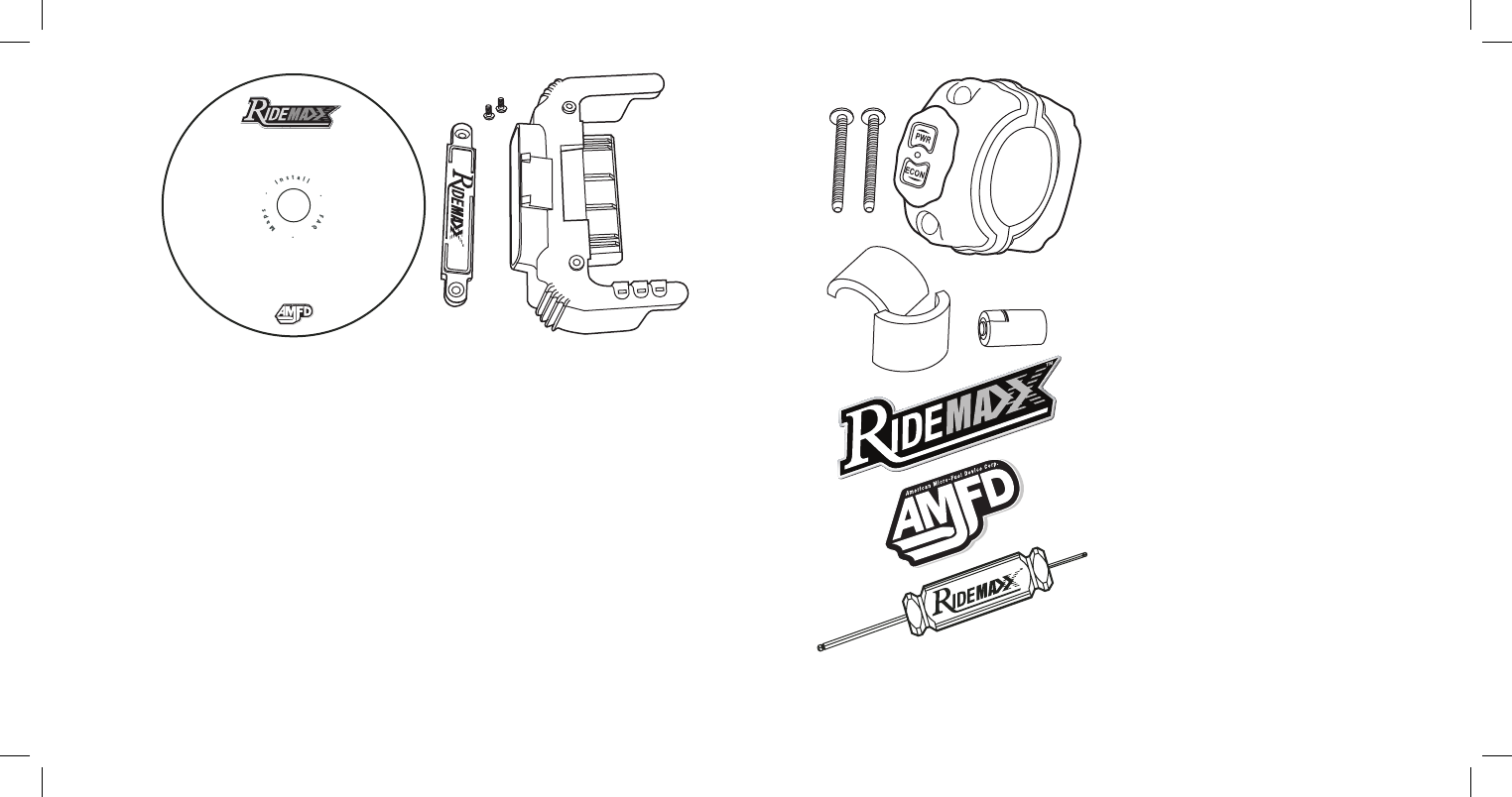
Your Parts:
1 FuelMaxx ECU Module
1 RideMaxx Locking Nameplate
2 FuelMaxx Bolts
1 RideTuner Handlebar Unit
2 RideTuner Handlebar Bolts
1 CR2 lithium Ion Battery
2 Handlebar space reducer gaskets
(for 1″ Handlebars)
1 RideMaxx Hex Driver
(double ended)
1 RideMaxx Software CD
1 RideMaxx Decal
1 AMFD Decal
1 RideMaxx Bluetooth Passkey: 0000
In The Box
To validate your warranty, registration
must be completed within 30 days of your
purchase.
We ask that you please take the time
to accurately fill in the questions in the
registration process—they only take a
few minutes of your time, and will help
AMFD provide you with the excellence
of customer service, advanced tuning and
the support that you should expect.
Enjoy your RideMaxx EFI controller, we
sure enjoy ours—and thank you so-much
for your business.
—e AMFD Team

6
RideMaxx Quick Start Guide 7
Installation
Contents
Using RideMaxx 23
Exit Notes
FuelMaxx Installation For Softails 10
FuelMaxx Installation For Baggers 12
RideTuner Installation 18
Finishing Installation 22
Installing New Maps 24
RideTuner Battery 28
FCC 29
Warranty 30
FuelMaxx and RideTuner Overview 8
8
RideMaxx Quick Start Guide 9
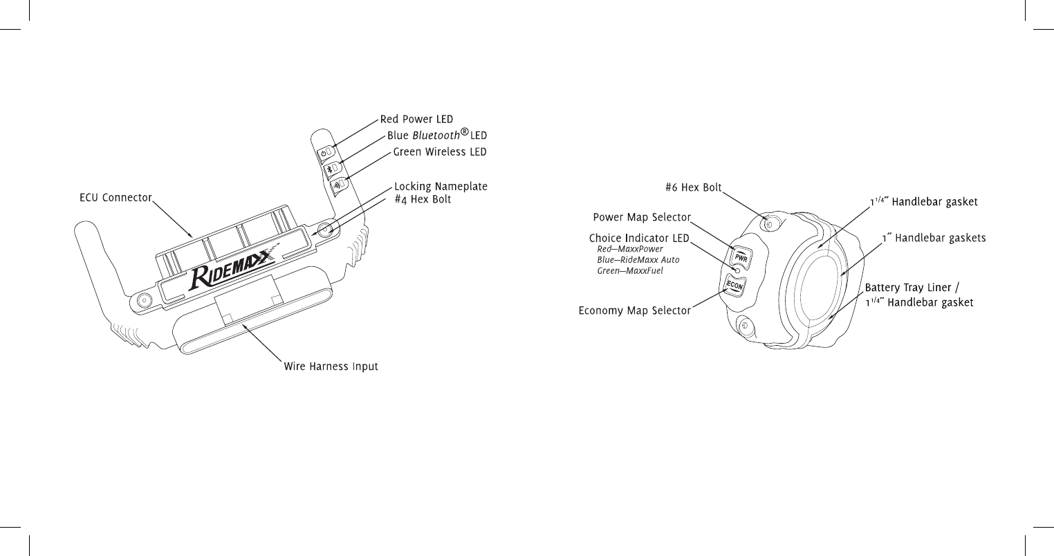
FuelMaxx and RideTuner Overview
RideMaxx: The FuelMaxx
The brain of the RideMaxx performance EFI control system
RideMaxx: The RideTuner
Your wireless control of the FuelMaxx module
e industry leading wireless Ride-
Tuner mounts directly onto your
handlebar. It is your direct means to
select from three separate options
(MaxxFuel Economy, MaxxPower,
and RideMaxx Auto) built into the
FuelMaxx module.
As the core of the RideMaxx fuel-
management system, FuelMaxx is the
brain. It is programmed to offer you the
best possible riding experience without
sacrifice. It is engineered with your specific
needs in mind.
10
RideMaxx Quick Start Guide 11
Softail FuelMaxx Installation
FuelMaxx on Softails
The ECU Plug-in Module Installation for Softails
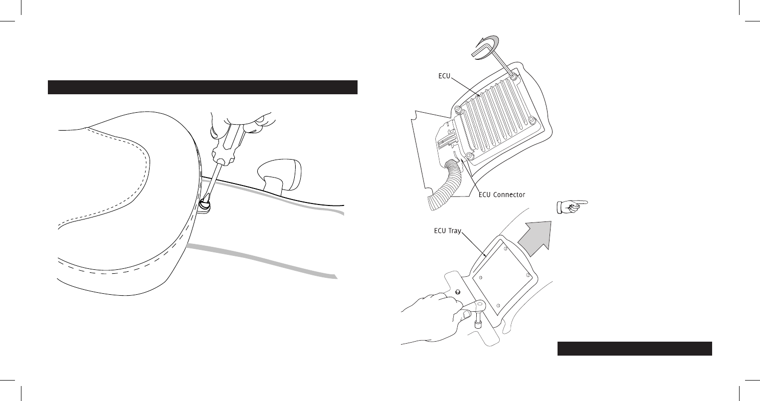
1. Remove your seat by unscrewing the securing bolt.
—Consult your bike’s manual for your specific seat removal instruction.
Prior to installation, please ensure that the ignition of your bike is turned off.
2. Using a 3/16˝ Allen Wrench, unbolt
all four ECU bolts and remove the ECU
while still attached to the ECU connector.
—Consult your bike’s manual for your specific
ECU removal instruction.
Softail install continued on page 14…
Ensure the ECU tray is located
at the maximum height on the
fender. is allows for needed clearance of
the FuelMaxx module. To do this, loosen the
bolts with a 3/8˝ wrench and slide the tray
up the fender. Retighten the bolts once in
position.
12
RideMaxx Quick Start Guide 13
Bagger FuelMaxx Installation
FuelMaxx on Baggers
The ECU Plug-in Module Installation for Baggers
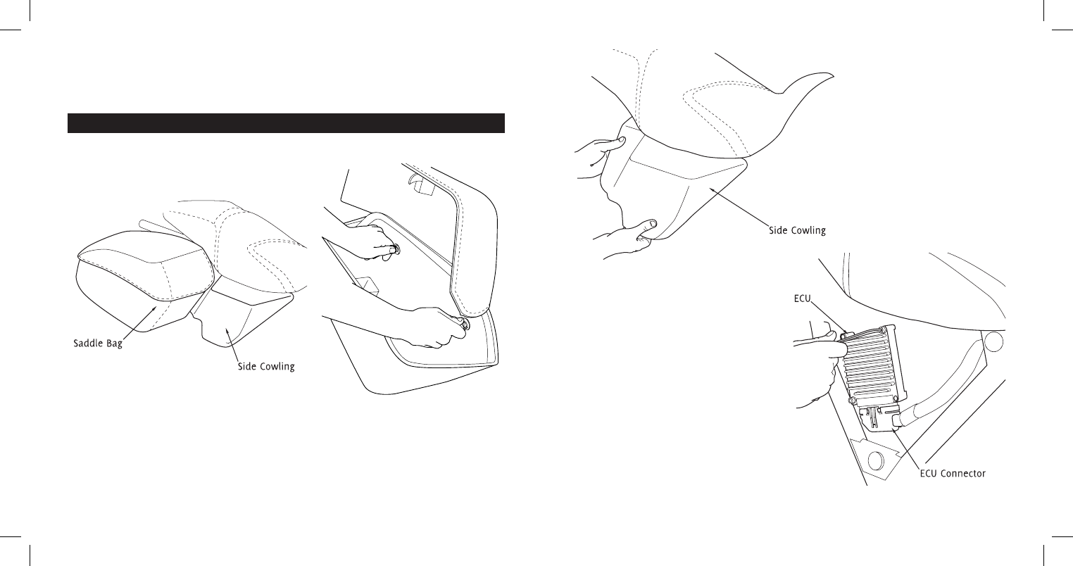
1i. Open your right side saddle bag and turn the two thumb screws to loosen and
remove the saddle bag. is allows access to the cowling beneath and ECU in turn.
—Consult your manual for specific bag removal instruction.
2i. Remove the side cowling that is
behind the right side saddle bag to gain
access to the ECU.
2ii. Using a 3/16˝ Allen Wrench,
unbolt all four ECU bolts and remove
the ECU while still attached to the ECU
connector.
Prior to installation, please ensure that the ignition of your bike is turned off.
FuelMaxx Installation14
RideMaxx Quick Start Guide 15
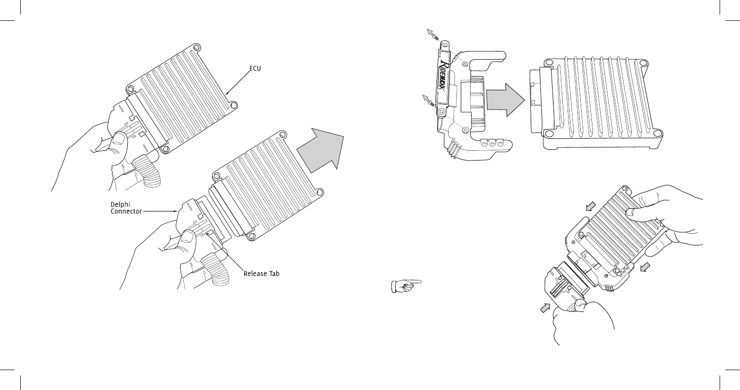
4. Remove the RideMaxx locking
nameplate from the FuelMaxx module
using the included 1/16˝ hex driver. en
plug FuelMaxx into the ECU as shown.
5. Plug the ECU connector into
the open side of RideMaxx FuelTuner.
3. Unclip the Delphi connector that plugs into the ECU.
—Squeeze the release tab and wiggle it off.
Continued FuelMaxx installation…
Ensure a tight fit is achieved and the
release tab clips to FuelMaxx.
FuelMaxx Installation16
RideMaxx Quick Start Guide 17
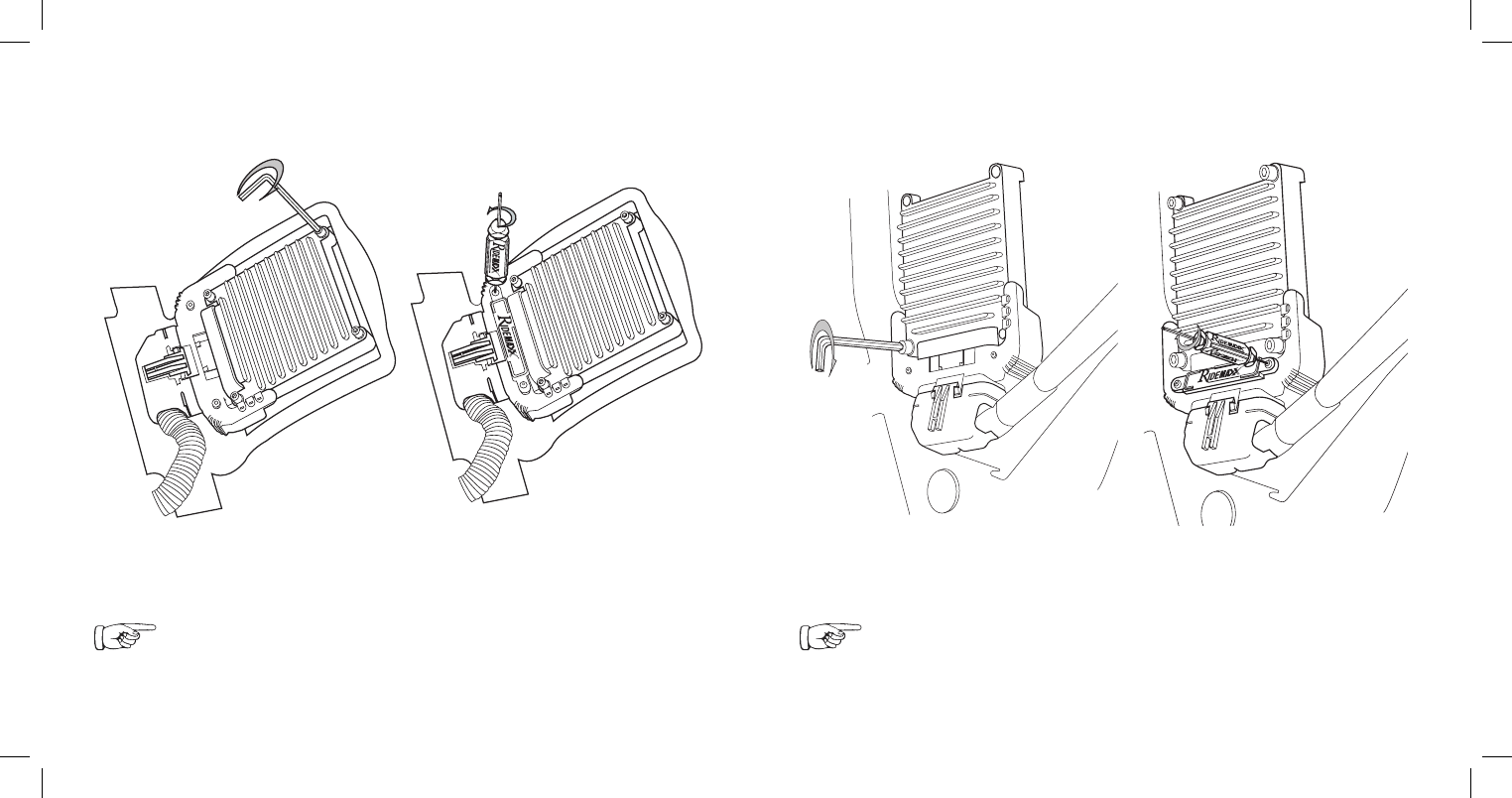
6. Using a 3/16˝ Allen Wrench, bolt
the ECU back down to the ECU tray.
6i. Using a 3/16˝ Allen Wrench, bolt
the ECU back down to the ECU tray.
7i. Using the included driver, replace
the RideMaxx locking nameplate.
Softail Installation
Remounting the ECU and FuelMaxx
Bagger Installation
Remounting the ECU and FuelMaxx
Consult your bike’s manual for your specific ECU reinstall instruction. Ensure
a tight fit to the ECU tray and the nameplate is seated flush and bolted securely.
Warning—Do not overtighten. Stripping inserts voids warranty.
Consult your bike’s manual for your specific ECU reinstall instruction. Ensure
a tight fit to the ECU tray and the nameplate is seated flush and bolted securely.
Warning—Do not overtighten. Stripping inserts voids warranty.
7. Using the included driver, replace
the RideMaxx locking nameplate.
RideTuner Installation18
RideMaxx Quick Start Guide 19
RideTuner Installation
The handlebar-mounted control module installation
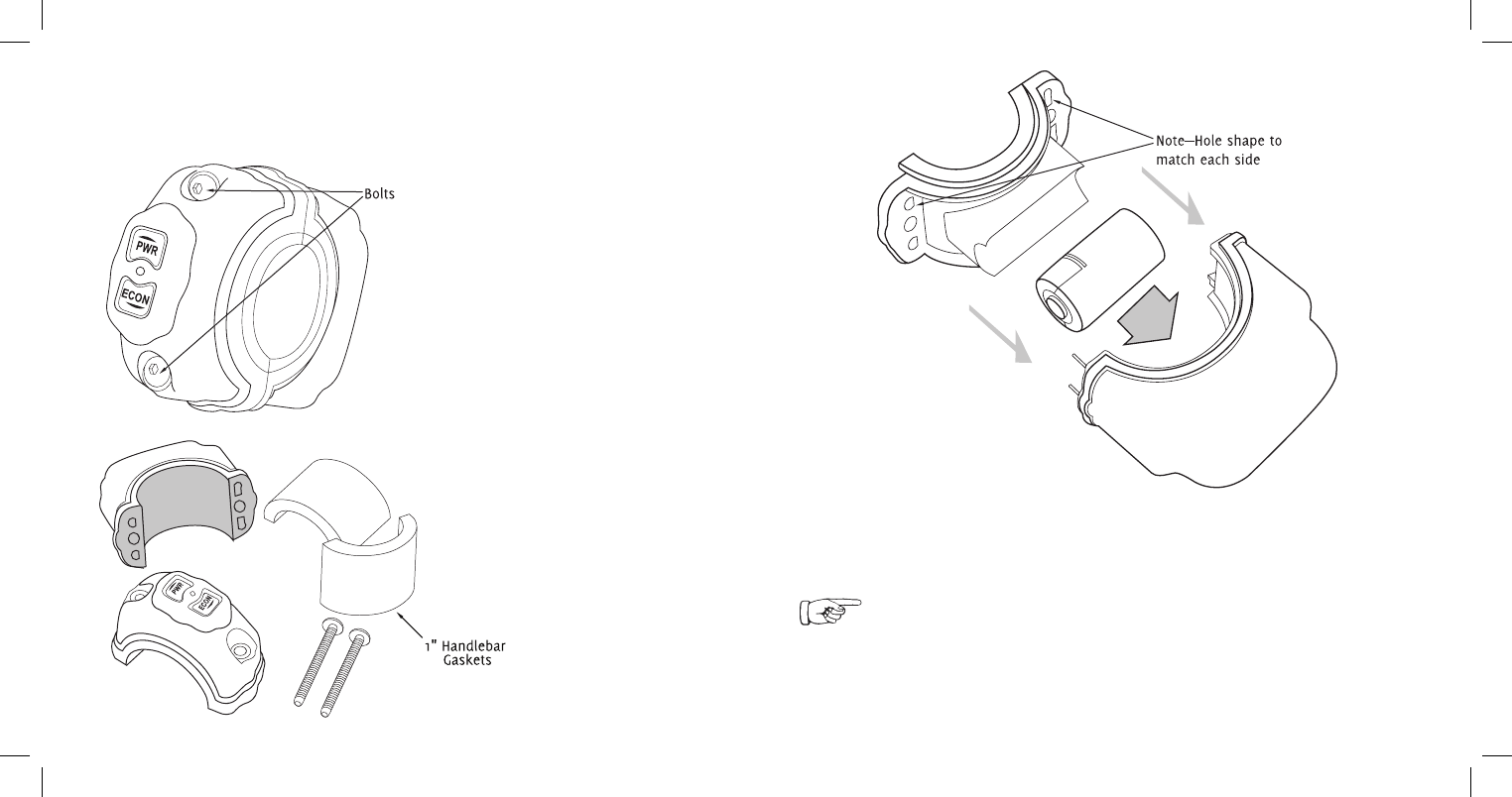
1. With the included RideMaxx 3/32˝
driver, remove the two bolts holding the
RideTuner together.
2. Separate the bottom half from the
top half without bending and remove
both semi circle gaskets.
3. Remove the rubber battery retainer
by gently peeling to expose the battery
tray inside. Insert the battery.
4. Place the tray liner back into the
battery tray of the RideTuner.
Note—polarity indication is in the battery tray for proper battery orientation.
Properly align and seat the rubber liner edges to secure a water tight fit.
Your battery is not under warranty; consult the warranty(pg.30) for details and the
battery information(pg.28) for acceptable replacements.
RideTuner Installation20
RideMaxx Quick Start Guide 21
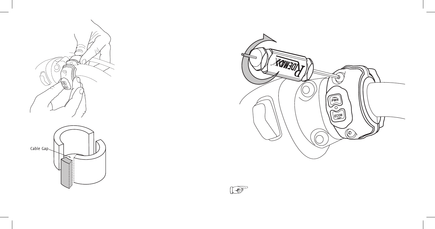
6. With the included RideMaxx 3/32˝ hex driver replace both bolts.
• For 1 inch handlebars replace the included
semi-circle reducer gaskets. ey are slightly
oversized for a proper compression fit.
• Where any cabling on your handlebar is
an obstruction, it may be necessary to trim a
small section of your reducer gasket to allow
the cable to pass through your RideTuner.
5. Adjacent to the switch housing, attach
the RideTuner around the handlebar for
a loose hold. Position the button faces for
your desired orientation.
Ensure a tight fit is acheieved with tight pressure on the gaskets.
Warning—Do not overtighten. Stripping inserts voids warranty.

22
RideMaxx Quick Start Guide 23
Finishing Installation
1. Without starting your bike, turn
the ignition switch from OFF to
IGNITION.
2. Observe the three LEDs on the
FuelMaxx ECU module:
—e red LED indicates your FuelMaxx
has power. Flashing indicates activity.
—e blue LED indicates your Bluetooth
enabled connection’s activity.
—e green LED indicates your Fuel-
Maxx is in wireless communication with
your RideTuner. Note: is LED will only
indicate when switching settings with your
RideTuner.
3. Observe the LED on the RideTuner
handle-mount module:
—Press either the PWR or ECON
button to awaken the RideTuner for a
blue indicator(RideMaxx Auto). Note: A
white indicator means the RideTuner is
looking for the FuelMaxx module.
—Press the PWR button for a red indica-
tor (MaxxPower).
—Press the PWR button a second time
to return to RideMaxx Auto.
—Press the ECON button for a green
indicator(MaxxFuel Economy).
—Press the ECON button a second time
to return to RideMaxx Auto.
—e LED will remain on for 10 seconds
until the RideTuner returns to sleep.
Finishing Installation
Testing your FuelMaxx and RideTuner modules
Using RideMaxx
The RideMaxx Auto, MaxxPower, and MaxxFuel Economy settings on the RideTuner
Two default pre-configured maps, per-
formance adjustment files, are installed
as MaxxFuel Economy and MaxxPower.
e third setting, RideMaxx Auto, does
not require a map. All three settings
eliminate backfiring and increase throttle
response.
For further information on maps please see
the Installing Maps section on page 24.
By default RideMaxx will start in the Ride-
Maxx Auto setting when you start your
bike. is setting will alternate between
the economy and power settings depending
on your throttle position.
e MaxxPower setting, once selected, will
prioritize horsepower and acceleration.
e MaxxFuel Economy setting, once
selected, will prioritize mileage.
When the FuelMaxx power LED indicates and the RideTuner toggles ride options (see
FuelMaxx green LED) RideMaxx is fully functional. Replace your seat and bolt (Softails)
or cowling and saddlebag (Baggers). Congratulations, RideMaxx is installed!
Note—RideMaxx will always start in the RideMaxx Auto setting when you start
your bike unless configured otherwise with the included software. Once the RideTuner
is asleep, any button press will awake it and indicate the current setting.
If your computer uses an alternative Bluetooth Wizard, please see our website
americanmicrofuel.com/support/bluetooth
Using RideMaxx24
RideMaxx Quick Start Guide 25
Installing Maps
Establish a Bluetooth enabled connection with Ridemaxx
1. Ensure your bike’s ignition switch is
switched from OFF to IGNITION.
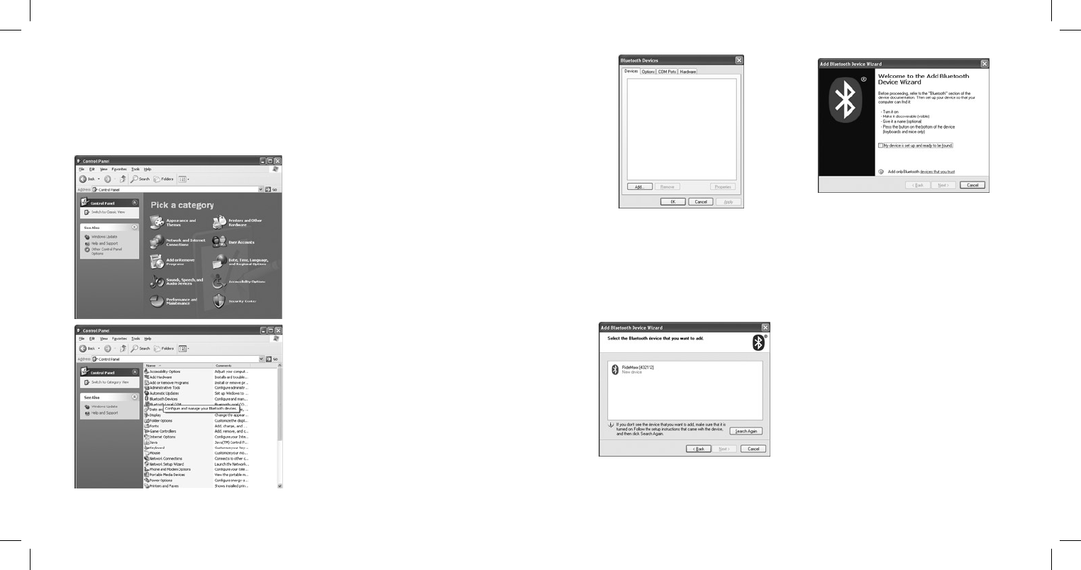
2. Navigate to your Control Panel. Find
it immediately under the Start Menu on the
right.
3. Switch to Classic View if you are in
Category View.
4. Locate the Bluetooth Devices icon
and double click.
5. In the Bluetooth Devices dialogue,
press the button Add to add your
RideMaxx device.
6. In the Add Bluetooth Device
Wizard check off the box My device is
set up and ready to be found and press
Next.
7. Once your RideMaxx device has been
found, select it and then press Next.
Using RideMaxx26
RideMaxx Quick Start Guide 27
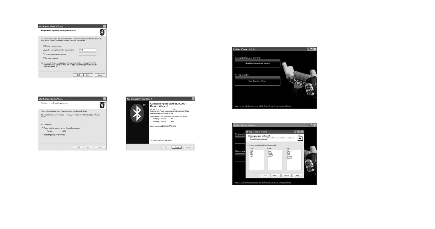
8. Select Use the passkey found in the
documentation.
10. From the included software cd, install the RideMaxx Wizard.
11. Press the RideMaxx Connection
Wizard button. Follow the on screen di-
rections and once asked for the RideMaxx
port, select the Outgoing COM Port you
wrote down previously.
12. Press the Map Selection button.
Follow the on screen directions to choose
the map for your bike.
13. Press the Send Map button to install
this file to RideMaxx.9. When the Wizard is finished installing the device, press Next. Write down the
Outgoing COM Port. Once the device is completed press Finish. Your device is now
ready to communicate with your computer.
Enter the passkey 0000 and press Next.

Using RideMaxx28
RideMaxx Quick Start Guide 29
Part 15.21
Changes or modifications not expressly
approved by the party responsible
for compliance could void the user’s
authority to operate the equipment.
NOTE: e manufacturer is not respon-
sible for any radio or TV interference
caused by unauthorized modifications to
this equipment. Such modifications could
void the user’s authority to operate the
equipment.
FCC Disclaimer
FuelMaxx FCC ID: WG2FM001
FuelMaxx IC: 7811A-FM001
RideTuner FCC ID: WG2RT001
RideTuner IC: 7811A-RT001
is device complies with part 15 of the
FCC Rules. Operation is subject to the
following two conditions: (1) is device
may not cause harmful interference, and
(2) this device must accept any interference
received, including interference that may
cause undesired operation.
QDID B010708
e included RideTuner Lithium Ion 3v
CR2 battery has a minimal usage time
and is not under warranty; due to the
constant communication between your
FuelMaxx module and RideTuner the
included battery’s charge may be depleted
quickly. Replacing your battery will extend
usage time. For example, a battery rated for
800mAh can last up to 90 days.
Replacement CR2 batteries are commonly
available at major retail stores from popular
brands such as Duracell, Energizer and
Panasonic; they are often referred to as
CR2 Photo or Camera batteries.
Capacity and length of usage may vary
from battery to battery. A battery’s mAh
rating is a general guide for which batteries
last longest.
RideTuner Battery
About your battery and replacing it
CR2 3v Litium Ion Battery
Duracell 925mAh
Kodak 850mAh
Energizer 800mAh
Panasonic 750mAh
Fuji—rechargeable 250mAh
Capacities may vary—use this chart
as a rough guide only.

Limited Warranty
How AMFD takes care of you
American Micro-Fuel Device Corp’s warranty obligations
are limited to the terms set forth below:
American Micro-Fuel Device Corp, (“AMFD”) warrants this
RideMaxx™ product (“product”) against defects in material
and workmanship for the period of one (1) year. The warranty
period begins on the date of original retail purchase.
This limited warranty is made only to the original end user
and purchaser (“you”) of the product and does not extend
to any subsequent purchasers or owners of the product. The
“original end user” is the first user to put the product into
service in any fashion. It is your responsibility to establish
the warranty period by verifying the original purchase date.
Accordingly, to avoid denial of coverage or dispute, you MUST
register your warranty either online at the AMFD website or
return the warranty/registration card to AMFD within thirty
(30) days after the date of purchase. This limited warranty
is void should you NOT register your warranty within thirty
(30) days of the date of purchase. If you discover a defect,
AMFD will, at its option, repair or replace this product
with a new or reconditioned product at no charge to you,
provided you return it during the warranty period, with
transportation charges prepaid, to AMFD. (You can obtain
additional information by contacting AMFD at the address
printed in this manual). Please attach your name, address,
telephone number, and a copy of the bill of sale as proof
of date of original retail purchase, as well as a detailed
description of the problem for which warranty service is
requested. Prior to returning the product, you must obtain
a Return Merchandise Number (RMA#) from AMFD. Contact
AMFD directly to obtain your RMA#. You are responsible
for packaging the product to be returned. If the repairs are
covered by this Limited Warranty and if the product was
properly shipped to AMFD, AMFD will pay the return shipping
charges. This limited warranty applies only to RideMaxx™
products manufactured by AMFD that can be identified by
the “RideMaxx™” trademark, trade name, or logo affixed
to them. This limited warranty does not cover: damage
resulting from the accidental, misuse, abuse, or neglect
and/or damage during any type of transportation resulting
from improper packaging; damage to any product which
has been altered in any fashion, including the alteration
or removal of any AMFD serial number; damage resulting
from causes other than product defects, including and not
by way of limitation, lack of technical skill, competence, or
experience of the user, and/or failure to use the product
in accordance with the instructions provided in the User’s
Manual; and service performed by an unauthorized person
or entity. Any implied warranties including fitness for
use and merchantability are limited in duration to the
period of the expressed limited warranty set forth above.
The remedies provided under this limited warranty are
exclusive and in lieu of all other remedies. AMFD hereby
expressly disclaims liability and shall not be responsible
in any way for incidental, consequential and contingent
damages of any kind or nature, including, without limitation:
damages to persons or property, whether a claim or such
damages is based upon warranty, contract, tort or otherwise;
damages due to or arising out of the loss of data; or lost
profits, inconvenience, loss of transportation or otherwise.
AMFD shall not be responsible for any damages caused by
the presence of error or omission in any of its manuals,
instructions or related materials.
Exit Notes30
Serial / Registration Number: