American Security spol s r o P-ADSC 58 kHz Deactivator User Manual
American Security spol. s r.o. 58 kHz Deactivator
User Manual
www.amersec.com
TECHNICAL USER MANUAL
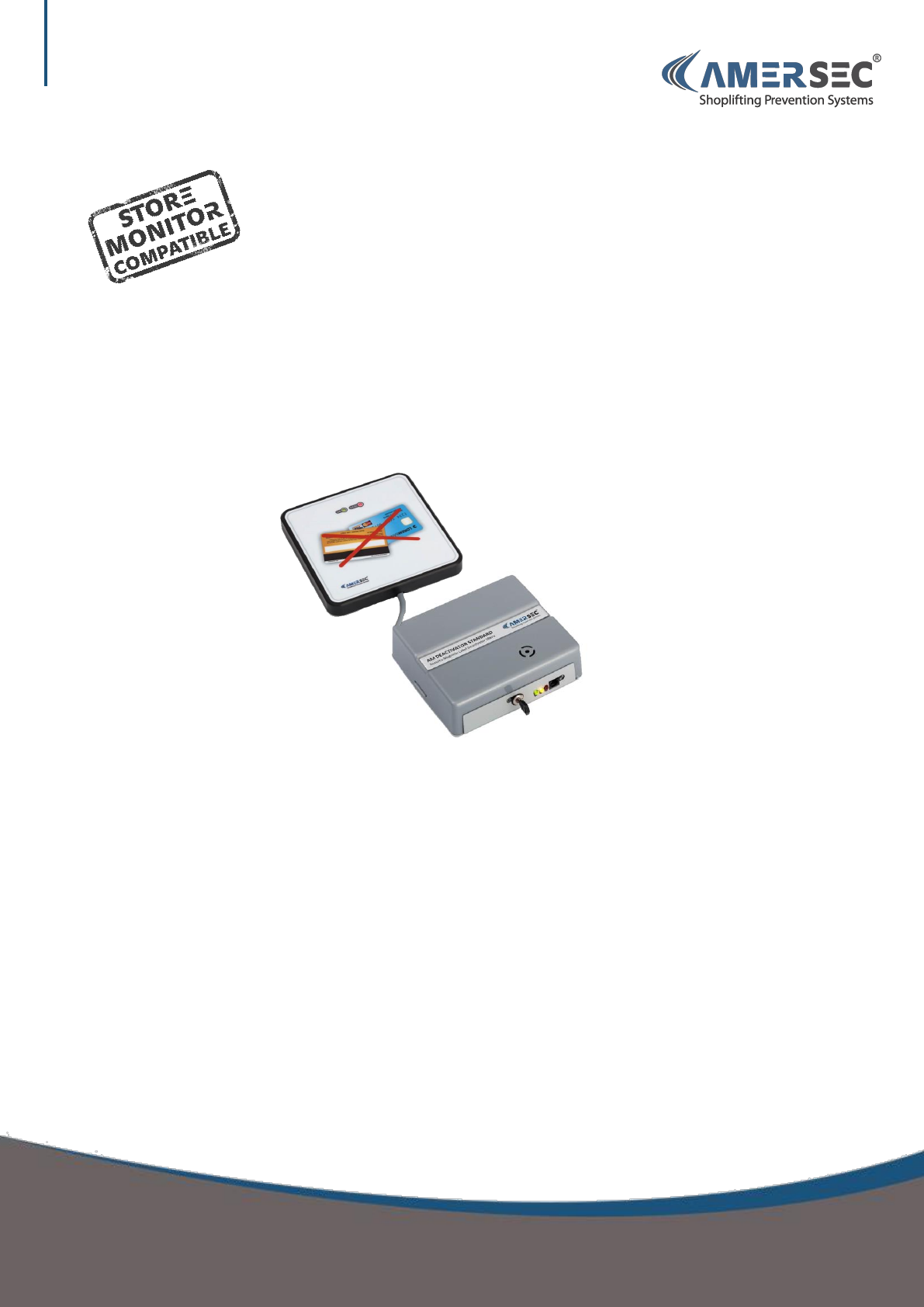
AM DEACTIVATOR
USER MANUAL – AM DEACTIVATOR
Confidential and proprietary information, for internal use only

USER MANUAL – AM DEACTIVATOR PAGE 2 of 9
This document was created to provide the intended recipient documentation for technician purposes only. Any other usage of this document is an illegal and unlawful act. This document is a confidential and proprietary document of American Security spol. s r.o. and consists of information that is protected by copyrights
or intellectual property protection of other subjects. All other information, which is not generally known, is intellectual property of American Security spol. s r.o. This document including any and all attachments hereto is intended solely to be used by individuals or entities to which it is addressed. If the reader of this
document is not the intended recipient, or an employee or agent responsible for delivering this document to its intended recipient, you are herewith notified that any dissemination, distribution, copying or retention of this document or the infor mation contained herein is strictly prohibited. If you have received this
document in error, please notify us at info@amersec.com immediately and permanently delete and/or destroy the original and any copy or printout thereof.
Contents
1.0 PRODUCT DESCRIPTION ............................................................................................................................................................ 3
1.1 Controller ................................................................................................................................................................................ 3
1.2 Pad ........................................................................................................................................................................................... 4
2.0 INSTALLATION GUIDE ................................................................................................................................................................ 4
2.1 Required Materials .................................................................................................................................................................. 4
2.2 Pre-Installation ........................................................................................................................................................................ 4
2.3 Connect Cables ........................................................................................................................................................................ 4
2.4 Test .......................................................................................................................................................................................... 5
2.5 Connect Controller to PC ......................................................................................................................................................... 5
2.6 Software – Main Settings ........................................................................................................................................................ 6
2.7 Software – Synchronization .................................................................................................................................................... 7
2.7 Software – Other Pages ........................................................................................................................................................... 8
3.0 TECHNICAL SPECIFICATIONS ...................................................................................................................................................... 9
4.0 DECLARATION ............................................................................................................................................................................ 9
USER MANUAL – AM DEACTIVATOR PAGE 3 of 9
This document was created to provide the intended recipient documentation for technician purposes only. Any other usage of this document is an illegal and unlawful act. This document is a confidential and proprietary document of American Security spol. s r.o. and consists of information that is protected by copyrights
or intellectual property protection of other subjects. All other information, which is not generally known, is intellectual property of American Security spol. s r.o. This document including any and all attachments hereto is intended solely to be used by individuals or entities to which it is addressed. If the reader of this
document is not the intended recipient, or an employee or agent responsible for delivering this document to its intended recipient, you are herewith notified that any dissemination, distribution, copying or retention of this document or the infor mation contained herein is strictly prohibited. If you have received this
document in error, please notify us at info@amersec.com immediately and permanently delete and/or destroy the original and any copy or printout thereof.
1.0 PRODUCT DESCRIPTION
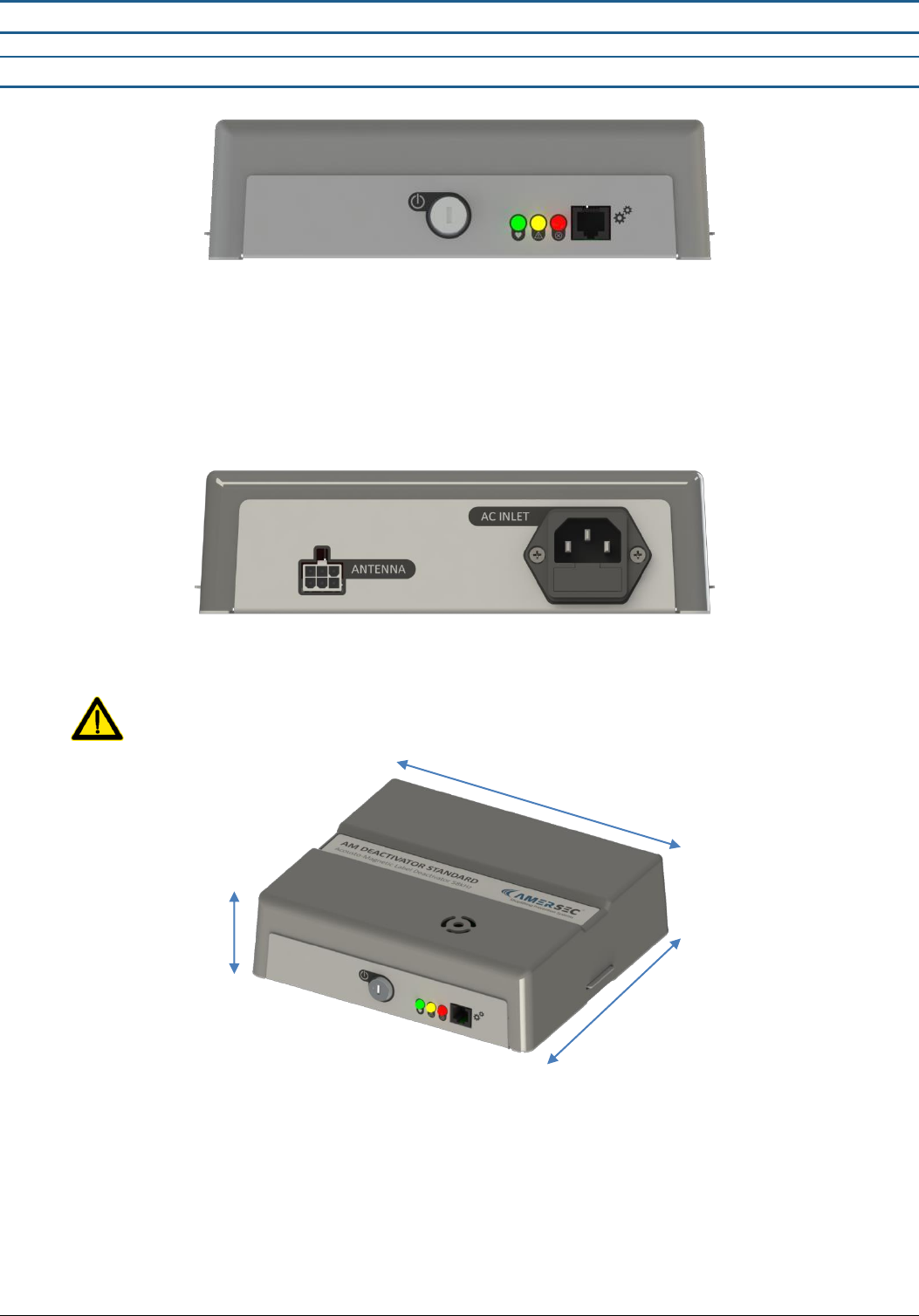
1.1 Controller
Power Switch: On/Off with Key – supplied with controller
LEDs
o Green (Status): Flashes slowly when switched on and operating normally. Flashes quickly when switched off
or during error
o Yellow (Warning): Indicates that the deactivator is switched off or a setting may be incorrect
o Red (Error): Indicates that an error has occurred
RJ11 Port: Connect your Hardware Key for setup or eComm Module for Remote Service
Antenna: Connector for deactivator pad
AC Inlet: Standard mains power cable for 110-240VAC, 50-60Hz
Deactivator is supplied for 220V. For 110V an extra step is required before powering on! See Section 2.3 for
details.
185 mm
170 mm
51 mm
USER MANUAL – AM DEACTIVATOR PAGE 4 of 9
This document was created to provide the intended recipient documentation for technician purposes only. Any other usage of this document is an illegal and unlawful act. This document is a confidential and proprietary document of American Security spol. s r.o. and consists of information that is protected by copyrights
or intellectual property protection of other subjects. All other information, which is not generally known, is intellectual property of American Security spol. s r.o. This document including any and all attachments hereto is intended solely to be used by individuals or entities to which it is addressed. If the reader of this
document is not the intended recipient, or an employee or agent responsible for delivering this document to its intended recipient, you are herewith notified that any dissemination, distribution, copying or retention of this document or the infor mation contained herein is strictly prohibited. If you have received this
document in error, please notify us at info@amersec.com immediately and permanently delete and/or destroy the original and any copy or printout thereof.
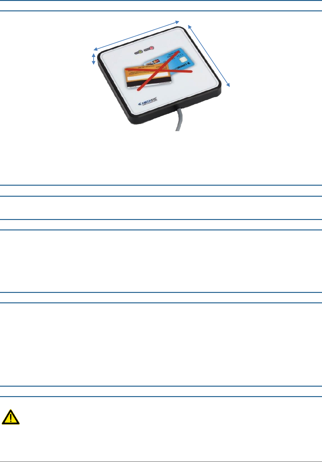
1.2 Pad
Green (ON) LED: Flashes slowly when deactivator is switched on and operating normally
Red (DEAC) LED: Indicates deactivation. LED is ON if the deactivator is switched off
2.0 INSTALLATION GUIDE
This section outlines the step-by-step processes for installing the AMERSEC® AM STANDARD DEACTIVATOR.
2.1 Required Materials
Deactivator Controller
1 Pad
mains power cable (supplied with controller)
USB Hardware Key with telephone cable
Laptop with Windows XP or later and Smart EAS Configurator installed
2.2 Pre-Installation
The following checklist should be completed prior to arriving on-site with the system.
□ Make sure you have installed the latest/correct Smart EAS Configurator Application and have a USB Hardware Key!
□ Is Remote Tuning required? An eComm Module with internet connection is required. IP settings should be
collected before installation. For these requirements please refer to the eComm User Manual.
eComms should be pre-configured before arriving on-site! See the eComm User Manual for details.
2.3 Connect Cables
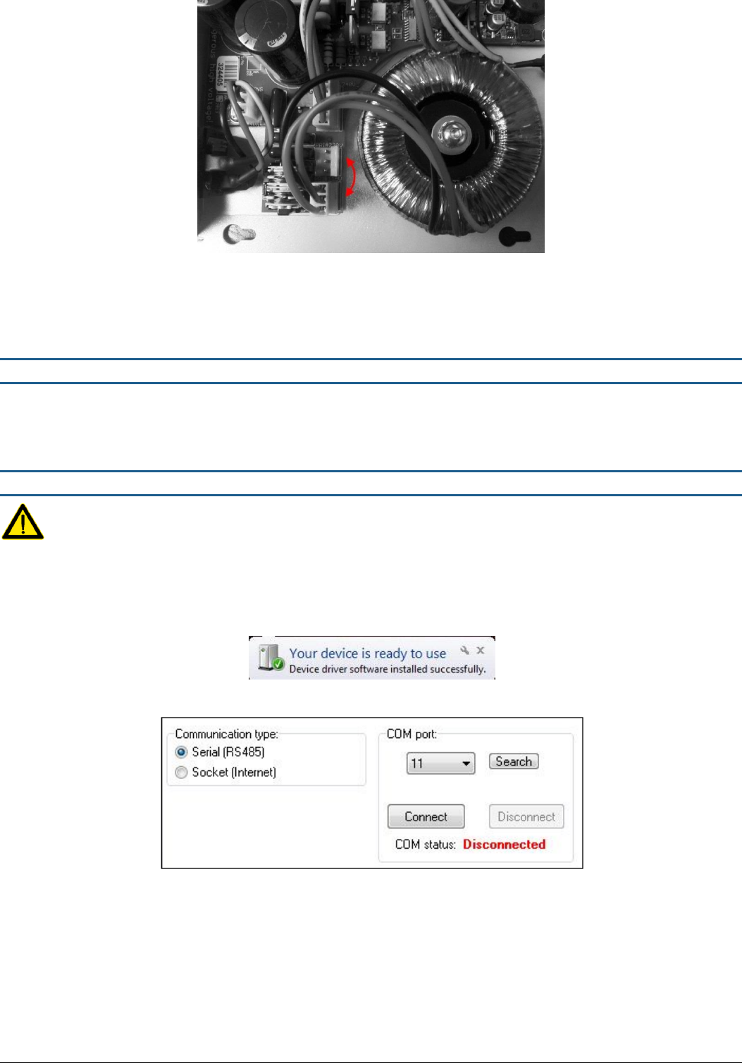
For 110V supply, open the controller and move the toroid transformer supply connector from the 230V pins to the
115V pins before powering on the deactivator!
160 mm
160 mm
cable = 150 cm
22 mm
USER MANUAL – AM DEACTIVATOR PAGE 5 of 9
This document was created to provide the intended recipient documentation for technician purposes only. Any other usage of this document is an illegal and unlawful act. This document is a confidential and proprietary document of American Security spol. s r.o. and consists of information that is protected by copyrights
or intellectual property protection of other subjects. All other information, which is not generally known, is intellectual property of American Security spol. s r.o. This document including any and all attachments hereto is intended solely to be used by individuals or entities to which it is addressed. If the reader of this
document is not the intended recipient, or an employee or agent responsible for delivering this document to its intended recipient, you are herewith notified that any dissemination, distribution, copying or retention of this document or the infor mation contained herein is strictly prohibited. If you have received this
document in error, please notify us at info@amersec.com immediately and permanently delete and/or destroy the original and any copy or printout thereof.
Connect the deactivator pad to the controller
Connect the mains power cable
Switch on with the provided key switch
2.4 Test
ALWAYS test the device for performance on-site before making holes in the cash desk. Every environment is different and the
original plan may need to be modified!
2.5 Connect Controller to PC
Requires Windows XP or later
Install software and then connect the USB Hardware Key to the PC and to the RJ11 port on the controller.
The Hardware Key is used as a USB converter, and for security. Only 1 key is needed for each technician, it is NOT left
at the installation with the system.
Open the Smart EAS Configurator AFTER the hardware driver is finished installing. Make sure the controller is powered
ON.
Select “Serial” communication.
The system will scan the COM ports on the computer. Select the correct COM port and press “Connect”. If multiple
COM ports show up in the list, you may need to try each one to find the correct port.
If you are unable to connect to the scanned COM port, you can manually find the correct COM port on your PC
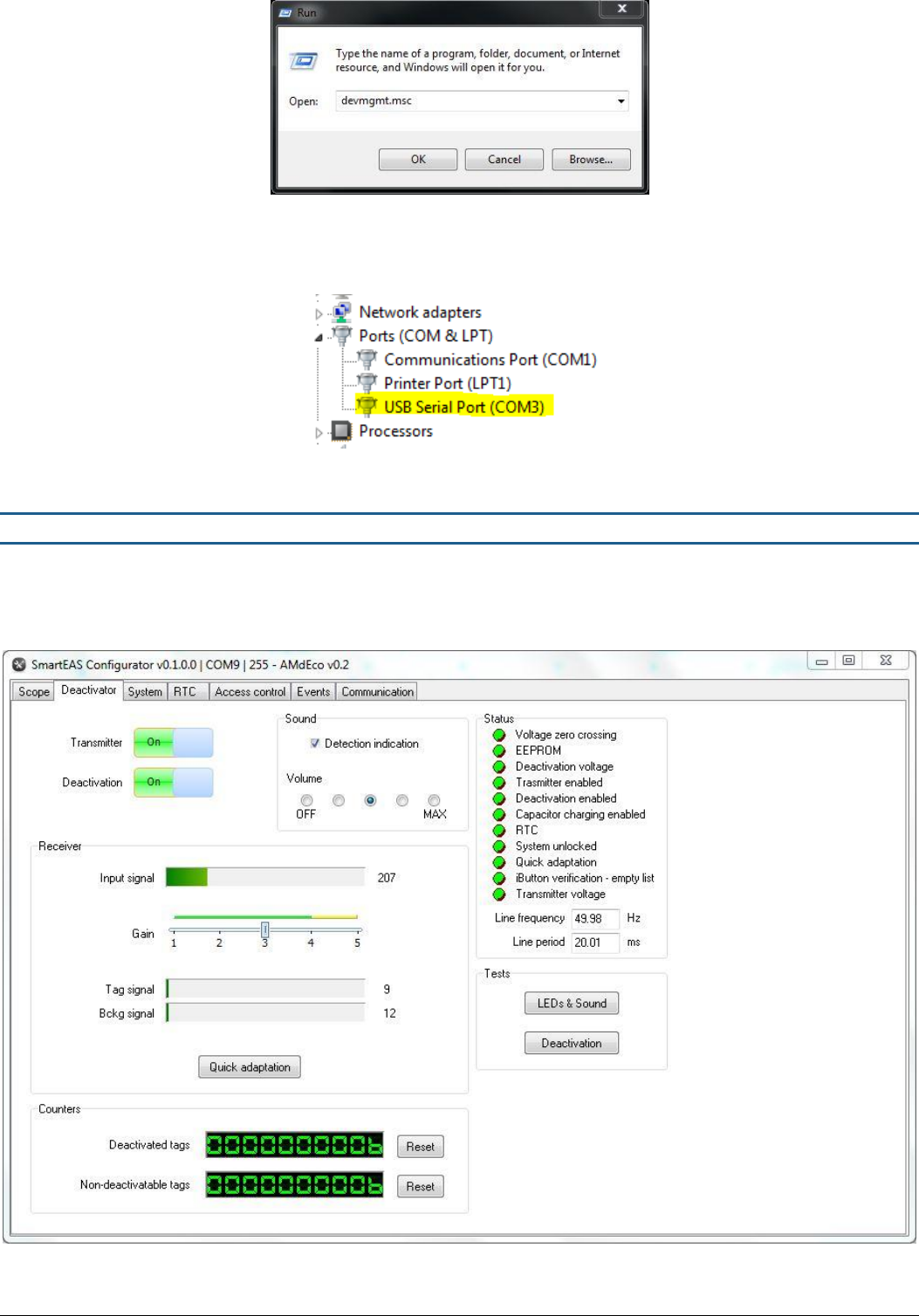
o Select Start -> Run -> devmgmt.msc -> OK
USER MANUAL – AM DEACTIVATOR PAGE 6 of 9
This document was created to provide the intended recipient documentation for technician purposes only. Any other usage of this document is an illegal and unlawful act. This document is a confidential and proprietary document of American Security spol. s r.o. and consists of information that is protected by copyrights
or intellectual property protection of other subjects. All other information, which is not generally known, is intellectual property of American Security spol. s r.o. This document including any and all attachments hereto is intended solely to be used by individuals or entities to which it is addressed. If the reader of this
document is not the intended recipient, or an employee or agent responsible for delivering this document to its intended recipient, you are herewith notified that any dissemination, distribution, copying or retention of this document or the infor mation contained herein is strictly prohibited. If you have received this
document in error, please notify us at info@amersec.com immediately and permanently delete and/or destroy the original and any copy or printout thereof.
Figure 1 - Open Device Manager
o When Device Manager is open, navigate to Ports (COM & LPT). The Hardware Key will be displayed as “USB
Serial Port (COMX). Select this port in the application and press “Connect”
2.6 Software – Main Settings
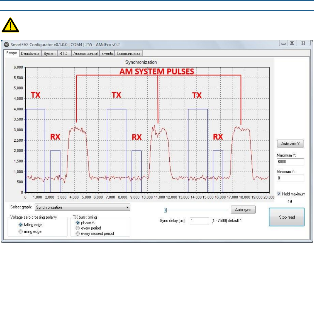
When you have successfully connected to the controller and have the pad connected, you can begin adjustment of the
deactivator. Settings are saved immediately to the controller after pressing the appropriate button (Set, Apply, Checkbox, etc.)
beside the setting. When entering a number value, press the “ENTER” key to confirm the setting and save it to the controller!
Figure 1 – Main Deactivator Page
USER MANUAL – AM DEACTIVATOR PAGE 7 of 9
This document was created to provide the intended recipient documentation for technician purposes only. Any other usage of this document is an illegal and unlawful act. This document is a confidential and proprietary document of American Security spol. s r.o. and consists of information that is protected by copyrights
or intellectual property protection of other subjects. All other information, which is not generally known, is intellectual property of American Security spol. s r.o. This document including any and all attachments hereto is intended solely to be used by individuals or entities to which it is addressed. If the reader of this
document is not the intended recipient, or an employee or agent responsible for delivering this document to its intended recipient, you are herewith notified that any dissemination, distribution, copying or retention of this document or the infor mation contained herein is strictly prohibited. If you have received this
document in error, please notify us at info@amersec.com immediately and permanently delete and/or destroy the original and any copy or printout thereof.
GAIN: The deactivator sensitivity is set by the GAIN slider. Set this value based on label deactivation height and
interference. Default value is 3
o For deactivators, the main cause of interference will be LCD screens at the cash desk. If you have interference
due to the screen, try orienting the screen or the pad in a different angle, or place the pad farther from the
screen.
SOUND: Adjust the volume of the sound for label detection or turn it off completely
TRANSMITTER ON/OFF: Turning off the transmitter will disable the device
DEACTIVATION ON/OFF: Turn off the deactivation function if you would like to just use the device as a tag/label
checker
COUNTERS: The deactivator will count deactivations and save to memory. If deactivation fails 3 times (this number can
be changed on the SYSTEM page – number of attempts to deactivate) in succession, it will be counted as a non-
deactivatable tag.
2.7 Software – Synchronization
It is recommended to first install the AM system, and then install the deactivators and synchronize to your AM
system. All AM systems and deactivators must be synchronized!
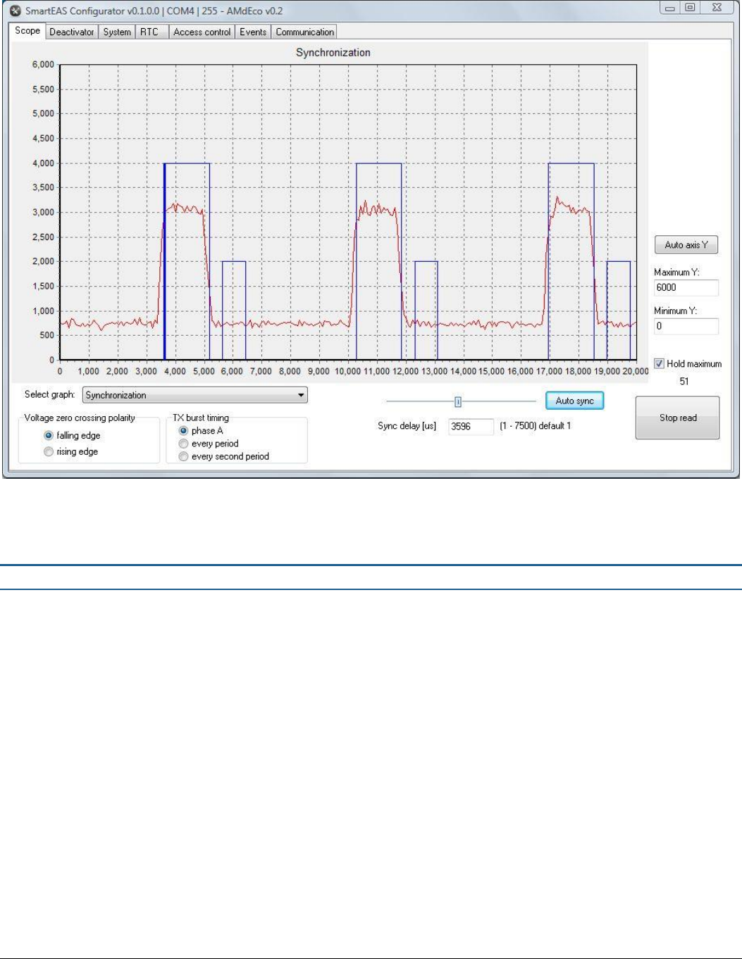
Figure 2 – Unsynchronized Deactivator
The figure above shows an un-synchronized deactivator. The red signal indicates all signals in the environment including any
other AM systems or deactivators. Select HOLD MAXIMUM and READ DATA to view these signals.
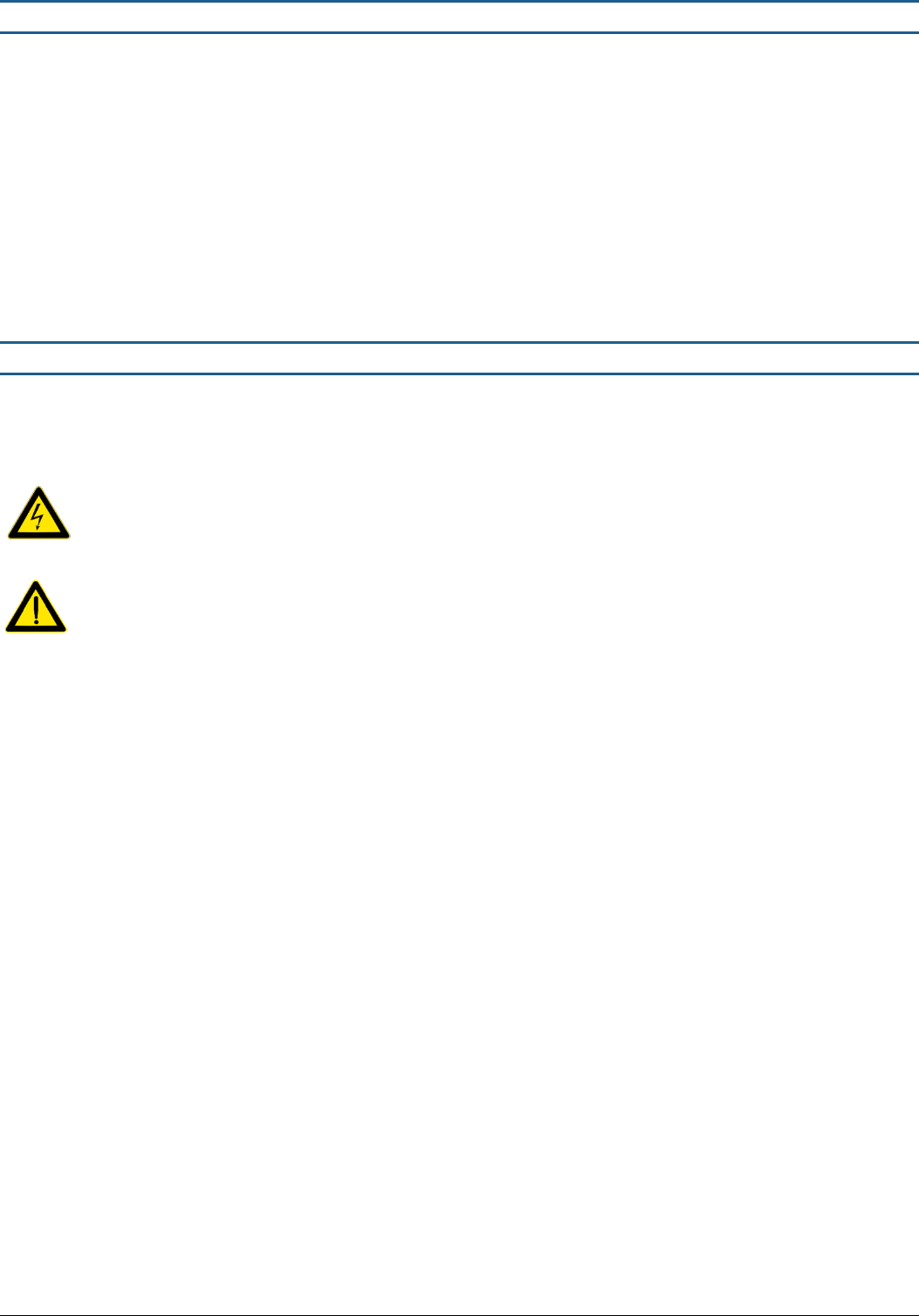
To synchronize, simply select AUTO SYNC, move the slider, or enter a value in SYNC DELAY to move your deactivator TX signal
(blue) on top of the red pulses. A synchronized deactivator is shown below.
USER MANUAL – AM DEACTIVATOR PAGE 8 of 9
This document was created to provide the intended recipient documentation for technician purposes only. Any other usage of this document is an illegal and unlawful act. This document is a confidential and proprietary document of American Security spol. s r.o. and consists of information that is protected by copyrights
or intellectual property protection of other subjects. All other information, which is not generally known, is intellectual property of American Security spol. s r.o. This document including any and all attachments hereto is intended solely to be used by individuals or entities to which it is addressed. If the reader of this
document is not the intended recipient, or an employee or agent responsible for delivering this document to its intended recipient, you are herewith notified that any dissemination, distribution, copying or retention of this document or the infor mation contained herein is strictly prohibited. If you have received this
document in error, please notify us at info@amersec.com immediately and permanently delete and/or destroy the original and any copy or printout thereof.
The deactivator pulses at a rate of 75Hz, as does the AM system. The graph displays 1 period of the mains frequency (20 msec)
so for this reason you will see 3 pulses.
VOLTAGE ZERO CROSSING allows you to switch polarity of detection of the mains frequency. This is like physically changing the
polarity of the power wires and shifts your signal by 10 msec, or 180 degrees.
Figure 3 – Synchronized Deactivator
2.7 Software – Other Pages
SYSTEM PAGE: Recommended to leave default settings
RTC PAGE: Synchronize internal clock to your PC if the deactivator will be connected to internet for remote service
ACCESS CONTROL: For future use
EVENTS: Allows the technician to view events that have occurred on the deactivator for troubleshooting purposes.
Events include On/Off status, deactivations, errors, etc.
COMMUNICATION: Change the bus address if the deactivator will be connected to internet for remote service
USER MANUAL – AM DEACTIVATOR PAGE 9 of 9
This document was created to provide the intended recipient documentation for technician purposes only. Any other usage of this document is an illegal and unlawful act. This document is a confidential and proprietary document of American Security spol. s r.o. and consists of information that is protected by copyrights
or intellectual property protection of other subjects. All other information, which is not generally known, is intellectual property of American Security spol. s r.o. This document including any and all attachments hereto is intended solely to be used by individuals or entities to which it is addressed. If the reader of this
document is not the intended recipient, or an employee or agent responsible for delivering this document to its intended recipient, you are herewith notified that any dissemination, distribution, copying or retention of this document or the infor mation contained herein is strictly prohibited. If you have received this
document in error, please notify us at info@amersec.com immediately and permanently delete and/or destroy the original and any copy or printout thereof.
3.0 TECHNICAL SPECIFICATIONS
Deactivation Height: up to 12 cm
Deactivation Speed: 2/sec
Pad-Controller Cable Length: 1.5 m
Power Input: 110-220VAC @ 50-60Hz
Power Consumption: 10W
Operating Frequency: 58kHz
Transmitted Pulse Width: 1600 µsec
Repetition Rate: 75Hz
Operating Temperature: 0-50°C
4.0 DECLARATION
Operate the device only as described in these operating instructions. Damage to hardware due to improper use will result in
loss of warranty.
WARNING! Do not open controller while connected to main power. RISK OF ELECTRIC SHOCK!
CAUTION! When connecting or disconnecting pad make sure deactivator is switched off.
This product conforms with the requirements of the following harmonized standards for electromagnetic compatibility:
- EN 55022: 2006 + A1: 2007;
- EN 61000-3-2: 2006 + A1: 2009+A2: 2009;
- EN 61000-3-3: 2008;
- ETSI EN 300 330-1 V1.7.1: 2010
- ETSI EN 300 330-2 V1.3.1: 2006;
- ETSI EN 301 489-1 V1.8.1: 2008;
- ETSI EN 301 489-3 V1.4.1: 2003.
This equipment has been tested and found to comply with the limits for a class A digital device, pursuant to part 15 of the FCC
Rules. These limits are designed to provide reasonable protection against harmful interference when the equipment is
operated in a commercial environment. This equipment generates, uses, and can radiate radio frequency energy and, if not
installed and used in accordance with the instruction's manual, may cause interference to radio communications. Operation of
this equipment in a residential area is likely to cause interference in which case the user will be required to correct the
interference at his own expense.
The user is cautioned that changes and modifications made to the equipment without approval of the manufacturer could void
the user's authority to operate this equipment.
Compliance is based on the use of shielded cables. Using cables other than shielded cables may result in interference.