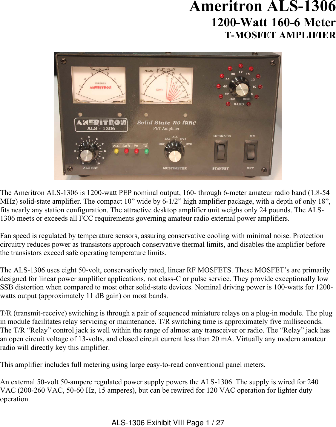
Ameritron 2WUALS1306 ALS1306 amateur radio linear amplifier User Manual Manual ALS1306

Ameritron ALS1306 amateur radio linear amplifier Manual ALS1306

Manual ALS1306

Ameritron ALS-13061200-Watt 160-6 Meter T-MOSFET AMPLIFIERThe Ameritron ALS-1306 is 1200-watt PEP nominal output, 160- through 6-meter amateur radio band (1.8-54 MHz) solid-state amplifier. The compact 10” wide by 6-1/2” high amplifier package, with a depth of only 18”, fits nearly any station configuration. The attractive desktop amplifier unit weighs only 24 pounds. The ALS-1306 meets or exceeds all FCC requirements governing amateur radio external power amplifiers. Fan speed is regulated by temperature sensors, assuring conservative cooling with minimal noise. Protection circuitry reduces power as transistors approach conservative thermal limits, and disables the amplifier before the transistors exceed safe operating temperature limits.The ALS-1306 uses eight 50-volt, conservatively rated, linear RF MOSFETS. These MOSFET’s are primarilydesigned for linear power amplifier applications, not class-C or pulse service. They provide exceptionally low SSB distortion when compared to most other solid-state devices. Nominal driving power is 100-watts for 1200-watts output (approximately 11 dB gain) on most bands. T/R (transmit-receive) switching is through a pair of sequenced miniature relays on a plug-in module. The plug in module facilitates relay servicing or maintenance. T/R switching time is approximately five milliseconds. The T/R “Relay” control jack is well within the range of almost any transceiver or radio. The “Relay” jack has an open circuit voltage of 13-volts, and closed circuit current less than 20 mA. Virtually any modern amateur radio will directly key this amplifier.This amplifier includes full metering using large easy-to-read conventional panel meters.An external 50-volt 50-ampere regulated power supply powers the ALS-1306. The supply is wired for 240 VAC (200-260 VAC, 50-60 Hz, 15 amperes), but can be rewired for 120 VAC operation for lighter duty operation. ALS-1306 Exihibit VIII Page 1 / 27
TABLE OF CONTENTSGENERAL OVERVIEW ........................................................................................................................1TABLE OF CONTENTS .......................................................................................................................2AMPLIFIER FEATURES ......................................................................................................................3INSTALLATION....................................................................................................................................4Airflow Clearances ............................................................................................................................4Accessory Equipment and Devices ...................................................................................................4Installation, Wiring, and Connections ................................................................................................4Station Ground ..................................................................................................................................5Grounding..........................................................................................................................................5Coaxial Line Isolators ........................................................................................................................6AMPLIFIER REAR PANEL ..................................................................................................................6POWER SUPPLY .................................................................................................................................7Power Line Requirements .................................................................................................................7Power Supply Features .....................................................................................................................8Power Supply Location......................................................................................................................8INTERCONNECTION WIRING.............................................................................................................9AMPLIFIER FRONT PANEL ..............................................................................................................10Meters (1 and 2) ..............................................................................................................................10INITIAL OPERATION .........................................................................................................................11OPERATION.......................................................................................................................................12MARS OR CAP OPERATION ............................................................................................................12ALS-1306 FUNCTIONAL OVERVIEW ...............................................................................................13General Operation...........................................................................................................................13Power Division.................................................................................................................................13PAM-606 (power amplifier modules) ...............................................................................................132KWF6 Lowpass Filter Assembly....................................................................................................14Control Functions and Protection Logic...........................................................................................14Band Decoding................................................................................................................................15Temperature....................................................................................................................................15Bias .................................................................................................................................................15Band................................................................................................................................................15Protection ........................................................................................................................................15Harmonics .......................................................................................................................................15SWR................................................................................................................................................16CIRCUIT BOARD DESCRIPTIONS ...................................................................................................162KWF6 ............................................................................................................................................16BS2 .................................................................................................................................................16CB2 .................................................................................................................................................16MB1.................................................................................................................................................16PAM-606 (power amplifier module) Boards.....................................................................................16PD8 .................................................................................................................................................16RJ45................................................................................................................................................17RLY .................................................................................................................................................17SWR................................................................................................................................................17SCHEMATICS AND INTERNAL WIRING ..........................................................................................18ALS-1306 Exihibit VIII Page 2 / 27
Amplifier FeaturesThis amplifier provides the following standard features:160- through 6-meter operation, full-power on six metersEight conservative linear-service rated, 50-volt MOSFET transistorsNew push-pull stripline PA layout with exceptional VHF performanceEnergy-efficient solid-state design greatly reduces heat, receive-mode power line draw <100-watts Exceptional harmonic suppressionOperational in a few seconds, no long filament warm-up timeClean layout with easy-to-service constructionQuiet variable-speed forced-air cooling systemPower module current and voltage meters with LED illuminationAccurate PEP Forward and PEP Reflected output power meteringPower module balance metering with PA unbalance protectionReflected power protectionThermal overload protectionBandswitch error protectionEasy to understand front panel LED indicators for rapid fault-error diagnosisStandard negative-going ALC output with front panel adjustmentALC metering and ALC LED indicatorFully-regulated external power supplyCompact size 17.5” deep x 7” high x 10.5” wideWeight amplifier section 24 poundsALS-1306 Exihibit VIII Page 3 / 27
InstallationPlease look your amplifier and power supply over carefully. Observe the air inlet and outlet ventilation holes. Facing the amplifier front panel, the cooling air inlets are on the top left and lower right side, including the right bottom. The warm air outlet is on the lower left side of the cabinet as viewed from the normal operating position (front view). While outlet air will not be particularly warm, it is never a good idea to have warm air blow into heat sensitive equipment, such as transceivers or other power amplifiers. Have the same consideration for your new amplifier and power supply. Be sure the air inlet temperature isn’t substantially above normal room temperature. Ideally the air inlet should be kept below 32° C or 90° F, although temperatures up to 41° Cor 106° F are permissible. If ambient temperatures exceed these limits it might become necessary to reduce duty cycle or power.Warning: Do not block cooling air inlets and outlets! Never expose the amplifier to water or mist.Airflow ClearancesThe amplifier must have a clear area to the bottom, both sides, and top for proper airflow, and to the rear for interconnection wiring. It is especially important to avoid obstructions that block the air inlet on the top left, as well as both lower sides. Two inches clearance is normally adequate for full ventilation. Keep any papers or loose objects that might impede airflow away from the air inlets and outlets.Locate the amplifier and power supply away from sensitive equipment such as microphones, audio processing equipment, or low level audio or radio frequency amplifiers. Generally, the best location for the power supply is below the operating desk and away from antenna feed lines. This will keep fan noise and any RF coupling to a minimum.The power supply has an air inlet at the rear, and air outlets on the top. The highly efficient power supply produces very little heat, but the inlet and outlet must remain open to normal room temperature air. Accessory Equipment and DevicesOne of the most common causes of amplifier failures or erratic fault protection alarms is installation of antenna switches, lightning protection devices, or baluns with lightning spark gaps in high SWR lines. If your antenna system has an SWR high enough to require an antenna tuner, do not use 50-ohm lightning protection devices after the tuner.Installation, Wiring, and ConnectionsThe power supply is factory wired for 200-260 Vac. It uses a standard NEMA-6-15P 15-ampere 240-volt plug. The round center pin is the safety ground. Do not remove the safety ground. CAUTION! Beforeconnecting  the  power  supply to  an  electrical  outlet,  always  be  sure  you have completed the following four steps:1. Insert the 15-ampere 250V fuses into the two black fuse caps. 2. Insert the fuse and cap assemblies into the power supply’s fuse holders. The fuses lock in place with a slight turn.3. Connect the power supply to the amplifier.4. Be sure the amplifier power switch is turned off.ALS-1306 Exihibit VIII Page 4 / 27
Caution! Fuses  have  both  voltage  and  current  ratings.  Use only  250V  rated  fuses  in  this device.  The  voltage  rating  generally  is  marked  on  fuses.  DO  NOT  use  automotive-type  low voltage  fuses  in  any  power  line  application.  For  240-volt  operation,  15-ampere  fast  blow fuses are required. Warning: Never  insert  the  power  supply  cord  into  the  outlet  until  you  have  completed  all installation  steps!  The  last  step,  after  verifying  all  connections,  is  connecting  the  power supply to the power mains. Position the amplifier at or near the desired location on your operating desk so you have access to the rear panel, and connect the rear panel cables. Do not connect the power mains at this time!Station GroundCommon rumor is that a station equipment ground reduces RFI (radio frequency interference) or improves signal levels. Generally, changes in RFI or signal quality with the addition or removal of a station groundindicate an antenna or feedline installation problem. Typical problems causing desktop RFI issues include the following:1. lack of suitable baluns2. improper feedline routing near antennas, or improperly designed antennas3. antennas too close to the operating position4. poor equipment cabinet design, such as non-bonded or grounded equipment covers or panels 5. poorly designed low-level audio line shield entrances, such as shields allowed to enter cabinets instead of grounding at the enclosure entrance6. improper antenna feedline building entrance, lacking a properly grounded entrance panel     Rather than patching a system problem at the desk, it is much better to correct defects at the problem source. GroundingThe amplifier and power supply cabinets ground through a safety ground pin on the power plug. This system depends on a properly wired power outlet.Lightning protection grounds do very little good at the operating desk. Lightning protection grounds belong at the antenna cable entrance to the building. Antenna feedline and control entrance grounds must electrically bond, with low impedance and resistance, to the powerline entrance ground.RF grounds and lightning grounds are most effective at the antenna and at the feedline entrance, rather than the operating desk.There are ground lugs on the rear of the amplifier and power supply. These ground lugs are provided for use with a station ground buss on the desk. A station ground buss helps ensure equipment cabinets on the desk are close to the same electrical potential. These ground lugs are NOT for direct, independent, connections to external ground rods or ground systems. The ground lugs are for connections to a desktop ground buss system. A proper desk ground buss is a short, wide, conductor that runs the width of the operating position. All equipment should bond to that buss, unless a manufacturer specifies otherwise.ALS-1306 Exihibit VIII Page 5 / 27
Coaxial Line IsolatorsThe goal of every operating position is to maintain all equipment cabinets and housings at the same RF potential. Isolators on or near the desk are contrary to this goal, and actually promote or encourage cabinet or chassis RF potential differences. Never install coaxial line isolators between desktop radio equipment.Proper line-isolator installation points are either just outside the operating room entrance and/or close to the problem’s actual source. If the desktop has defective cables or connectors, or poor equipment cabinet design, locate and correct the actual problem. If an RF problem appears at the operating position, correction, repair, or replacement of defective equipment is in order.Amplifier Rear PanelAmplifier Rear Figure 150VDC INPUT To prevent connecting the power plug wrong, the large black multi-pin connector is indexed by the offset in two round pins. One round index pin is closer to the outer connector edge. Mate the round pins and holes and seat the male plug fully onto the amplifier rear panel pins.ALC Optional connection. Connects to radio ALC input. Mandatory if using a radio over 100 watts.RELAY Connect to radio amplifier keying line. Radio must pull this line below 2 volts to transmit.GND Connect to station ground buss. This connection is for desktop safety.RF IN Connect through good 50-ohm coaxial cable of any reasonable length to radio’s antenna output connector. This can be a smaller cable, such as RG-58/U. Do not use or install an antenna tuner on this port.RF OUT To 50-ohm antenna, antenna tuner, power meter. This is the high power output. 50-ohm coaxial cable and system beyond must safely handle at least 1200-watts.ALS-1306 Exihibit VIII Page 6 / 27
1.) If you use a desktop grounding buss system, connect the station ground buss to the rear panel wing nuts. National safety codes require the station ground electrically bond to the power mains safety ground at the building entrance. Do not connect the amplifier to its own isolated ground rod or ground system.2.) Connect the power supply to the amplifier.3.) Connect the RELAY line to the transceiver’s amplifier relay, amp, or tx port. This port is defined in radio manuals in amplifier interfacing sections. This port must pull low for transmit, and be open circuit when receiving. Relay control voltage from the ALS-1306 is 12 volts positive with only 15 mA current. You should always check your transceiver’s manual, but almost any standard transceiver directly interfaces with this amplifier.4.) Connect the RF OUT (output) port to the appropriate point in your station. This is the high power RF output cable. This connection would go to your 1500-watt rated Power/SWR meter, antenna, or antenna matching device. Good quality Mini-8 or RG-8X cables are acceptable for anything but RTTY use, although larger RG-8 style cables are normally preferred. Your antenna matching system, or antenna tuner, must connect to this port.5.) Connect the IN connector to your transceiver. Do not install any active antenna matching devices on this port. In general the shortest and most direct cable connection is best, although high quality cables can be very long without adverse effect on performance. RG-58/U or Mini-8 (RG-8X) style cables are acceptable. You should never use a tuner of any type on the amplifier input, nor should you drive this amplifier with over 100 watts peak envelope power. Never use a non-amateur radio device with this amplifier.6.) The ALC line is optional. In general, the internal ALC in the transceiver is adequate for power control.With transceiver power>100W, ALC should be used. The ALC monitors the RF output power and reflected power supplied by the ALS-1306 to the load. 7.) Operate the bandswitch manually during initial testing. Do not connect band decoders, band data lines, or computer interfaces until initial tests are completed and the amplifier is functioning normally.Power SupplyThe external power supply for the ALS-1306 is a voltage-regulated current-limited switching supply. It contains 14-volt positive and negative supplies, as well as dual 50-volt 25-ampere continuous (30-ampere peak) fully current-limited supplies. Each PAM (power amplifier module) in the ALS-1306 operates from independent 50-volt modules, giving a total dc supply rating of 2500 watts average power and 3000 watts peak power to the power amplifier modules.Power supply to amplifier interconnections are through a heavy-duty cable using a large Cinch Jones connector. Power Line RequirementsThis amplifier ships wired for a nominal mains voltage of 230 Vac. Maximum average powerline current at full power output is 12 amperes at 240 volts. Two 250-volt 15-ampere fuses fuse the power line. The switching power supply automatically adapts to any mains voltage between 200 Vac and 260 Vac, and does not require adjustments or tap changes within that range.   ALS-1306 Exihibit VIII Page 7 / 27
Note:  120-volt  power  mains  operation  is  possible  with  a  reduction  in  CW  or  RTTY  power. Because average power is very low, SSB operation is unaffected by 120-volt operation. 120-V fuse size is 25-amperes maximum.Power Supply FeaturesEfficient operation from 200-260 volts ac (12 amperes typical at full output power) Low standby and receive power drain, typically less than 100-watts with ALS-1306 attached and operationalGenerator and inverter friendly with acceptable powerline frequency range 40 to 400 Hz Fully-regulated current-limited outputsStep-start to limit stress on power supply componentsExceptional filtering and RFI suppression eliminates receiver birdies common to most SMPSCompact light-weight design Power Supply LocationLocate the power supply in a convenient ventilated area near the amplifier location. Avoid placing the power supply next to sensitive equipment, such as audio processors, transceivers, or microphones. For safety, ground the wing nut stud on the supply rear to the station ground buss. The station ground buss should comply with National Electrical Codes. NEC and fire protection codes mandate direct bonding of station ground rods or systems to the power line entrance ground system. If station ground rods are not bonded to the utility entrance ground, likelihood of equipment or property damage and personal risk increases.ALS-1306 Exihibit VIII Page 8 / 27
Interconnection WiringInterconnections Figure 2ALS-1306 Exihibit VIII Page 9 / 27
Amplifier Front PanelAmplifier Front Figure 3 The front panel contains the following indicators and controls. To prevent damage, become familiar with the front panel before operating the amplifier.Meters (1 and 2)This amplifier has two dual-movement panel meters. The left-hand meter (fig.2 ref 1A and 1B) continuously reads power amplifier module currents up to 25-amperes. Keep current below 25-amperes when using CW. On SSB voice, displayed current will typically be less than 10-amperes. Currents reaching full or beyond full scale for short periods are generally not harmful. The power supply has over-current shutdown. The over-current protection resets by turning the amplifier OFF for several seconds, and then restarting the amplifier.The right-hand meter’s left scale-arc (fig.2 ref 2A) continuously indicates forward peak envelope power (PEP) directly in kilowatts. The scale is 100 watts, or 0.1 kW, per meter scale picket. PEP is the highest instantaneous average or effective heating power during one (or more) complete radio frequency cycle(s) at the modulation envelope crest. PEP has no fixed relationship to long-term average power in amplitude modulated or SSB transmissions. With constant amplitude carriers, like a steady CW carrier, PEP and average powers are equal.The right-hand meter’s rightmost scale-arc (fig.2 ref 2B) is used for PEP reflected power, ALC power setting (power scale times ~ten), and combiner imbalance (power scale direct) using the upper scale numbers and pickets. Notice power calibrations are not evenly spaced. Lower scale numbers and pickets, because they ALS-1306 Exihibit VIII Page 10 / 27
indicate voltage, are evenly spaced. The lower right scale (fig.2 ref 2B) is for power amplifier module voltagesHV1 and HV2 (0-70 volts).    Initial OperationFor your personal and equipment safety, double-check all wiring and connections (fig. 1) before turning power on. After you have verified amplifier connections, follow the procedures below. The following steps are necessary during initial checks:1. Place the MULTIMETER switch (fig.2 ref 5) in the HV2 position. Place the ALC SET control (fig.2 ref 4) full clockwise (10 on knob scale). The multimeter is the right-side scale on the rightmost panelmeter (fig.2 ref 5B).1. With the STANDBY/OPERATE switch (fig.2 ref 7) on STANDBY, turn the power switch (ref 8) ON. 2. There will be a slightly delayed “click” from the power supply. HV2 (fig.2, ref 2) should immediately rise to near full scale, and after a slight delay, you should hear another “click”. The meters and the appropriate BAND LED (fig.2, ref 3) should illuminate. 3. The multimeter’s HV2 scale (fig.2, ref 2B, bottom right scale) should read between 45 and 55 volts.4. Change the meter switch (fig.2 ref 6) to HV1. The voltage should be the same as in step 4.5. Rotate the BAND switch (fig.2 ref 3) through all positions. The appropriate BAND LED will illuminate, and you should hear band-filter relays switch between 160-80, 80-40, 40-30, 20-17, 15-12, and 10-6 selector position changes. 6. Set the BAND switch (fig.2 ref 3) to a band where a good 50-ohm high-power load is connected. 7. Change the meter switch (ref 6) to REF. In this position, the multimeter indicates reflected power.8. With no modulation in the FM, AM, RTTY, or CW mode, and the amplifier still on standby, adjust your exciter power to about ten watts. This is to have a steady unmodulated carrier. Verify you have very low power, ideally around 10-watts carrier (not critical), and the antenna system VSWR is low. You should see almost no meter deflection on the reflected power scale (fig.1 ref 2) with the MULTIMETERswitch in the REF position. If you see reflected power deflection, check your RF cables. Reminder: You cannot use a tuner in your radio, or between your radio and this amplifier, to match the antenna system. Antenna matching must be between the amplifier and the antenna, and the antenna tuner and anything installed beyond the amplifier must conservatively be able to handle over 1200-watts of carrier or peak envelope power.9. Place the amplifier in OPERATE position (fig.2 ref 8). Be sure the BAND on the amplifier matches the band selected on the transceiver. 10.  Place the transmitter or transceiver into transmit in a FM, AM, RTTY, or CW mode. The green TXLED (fig.2 ref 6) should light. The forward power (fig.2 ref 2A) should increase to over ten times the initial exciter power reading. Reflected power should remain very low, and PA current should increase slightly on both scales of the current meter (fig.2 ref 1A and 1B). No other LED’s should illuminate. ALS-1306 Exihibit VIII Page 11 / 27
11. Briefly increase exciter power until the amplifier reaches 1200-watts output, or increase exciter power to a maximum power of 100-watts without exceeding 1200-watts amplifier power.12. After you have verified all of this, the amplifier is ready to operate.With some drive power less than 100-watts PEP, this amplifier should show approximately 1200-watts of output power. This can vary slightly from band-to-band, and may slightly exceed 100-watts on some bands for some amplifiers. 100-watts is a nominal figure.OperationThis amplifier covers all Amateur Radio frequencies below 54 MHz, as restricted by FCC or your local governing authority. Once you have established proper connections, please set the amplifier (Fig. 2, ref 3) to one of the following bands:Band Frequency Range Notes160 1.8 - 2.1 MHz80 3.2 - 4.2 MHz40 6.0 - 7.5 MHz30 7.5 - 14.0 MHz USA 30-meter power limit currently 200-watts20 13.5 – 14.5 MHz17 14.5 – 19.0 MHz15 19.0 – 22.0 MHz12 22.0 – 25.0 MHz Amplifier automatically disables above 25 MHz10 28.0 – 30.0 MHz Amplifier automatically disables below 28 MHz6 50.0 – 54.0 MHzFrequency Limits Table 1Caution: This  amplifier  has  an  FCC  mandated  automatic  disconnect  and  other  features preventing  27-MHz  operation.  There  is  no  available  circuitry  or  control  provision  to circumvent this lockout. MARS or CAP OperationFor licensed amateur radio operators participating in Military Affiliate Radio Systems or CAP operation, this amplifier is suitable for use on all frequencies between 1.8 and 54 MHz with some precautions. The upper frequency limits are in bold type in the table above. Do not operate above the bold-type frequency limits in thetable above or PA (power amplifier) or filter damage may occur. Ameritron guarantees to exceed FCC part 97.307 harmonic suppression standards, as of January 2013, inside amateur bands listed in the table above. Ameritron does not guarantee harmonic suppression or operation outside amateur bands. Most commercial services prohibit use of non-commercial radio equipment. This amplifier is inoperable between 25 and 28 MHz. Modifications allowing operation in the 25-28 MHz range is not available, irrespective of licensing or end-use.ALS-1306 Exihibit VIII Page 12 / 27
ALS-1306 Functional OverviewThe ALS-1306 is an amateur radio multiband radio frequency linear power amplifier. This device requires certification. This device complies with technical standards of CFR Title 47 part 97.317(a) and (b) as of April 2013. General OperationThis linear amplifier covers the 160, 80, 40, 30, 20, 17, 15, 12, 10, and 6-meter amateur bands. Up to 100-watts exciter power is applied to relay RLY1 on circuit board RLY. With the main power OFF, the STANDBY/OPERATE switch on STANDBY, with a fault warning LED illuminated, or with the rear panel RELAY jack ungrounded, RLY1 bypasses through RLY2 directly to the antenna port.When power is ON, the STANDBY/OPERATE switch in the operate position, and the rear panel RELAY control line held low (below 1 volt), exciter power is routed through RLY1 to the PD8 power divider board. Power DivisionThe PD8 power divider board attenuates the exciter input signal, and divides exciter power equally, between two 600-watt power amplifier modules. It is 50-ohms on all three ports, with 8.2 dB nominal attenuation to each output port.The PD8 circuit board consists of a conventional magic-T power divider, components T2 and R7. This T divides drive power into two equal-power signals. Each signal path has a 5 dB attenuator consisting of high power resistors R1 through R6. The 5 dB attenuators on each output port terminate the T in 50-ohms and provide an additional 10 dB of input port isolation between the two PAM’s. With a 50-ohm source, in excess of 30 dB port-to-port isolation occurs between PAM inputs. A minimum of 16 dB isolation occurs regardless of input port termination. The attenuators also work in concert with the magic-T to provide a 50-ohm input termination for each PAM. The 50-ohm termination and input port isolation results in unconditionally stable PAM’s. PAM-606 (power amplifier modules)Power amplification comes from two 600-watt power amplifier modules. Each PA module (PAM-606) uses four MFR-150 field effect transistors. Each MRF-150 has 100 mA to 300 mA quiescent current. Transistor conduction angle is slightly over 180-degrees, providing linear class-AB operation. While the precise value of quiescent current has little effect on linearity, it is very important to adjust all eight FET’s to the same quiescent current. Target current is typically 150 mA in this design. Normal dc drain operating voltage is approximately 50-volts. Be aware bias control rotation is reversed in CB2 boards, as compared to the previous generation ALS-1300’s CB1. When servicing any solid state PA, always verify function of bias and set for minimum bias before applying drain voltage. Unlike standard Motorola based modules, the PAM-606 modules use two diametrically opposed push-pull pairsof 150-watt MOSFET’s. The 300-watt push-pull pairs drive balanced VHF striplines. The balanced striplines combine at a matching transformer. The linear RF power FET’s mount on a forced-air-cooled aluminum heatsink. Two dc fans cool each PAM-606 module. Two thermistors (PAM-606 R2) sense power amplifier transistor temperature. Transistor temperature thermistor R2 regulates bias voltage, reducing bias voltage as transistor temperature increases. This bias feedback system keeps transistor quiescent current stable independent of ALS-1306 Exihibit VIII Page 13 / 27
transistor junction temperatures. PAM-606 thermistors R2 also feed a comparator that removes drive when transistor temperatures approach unsafe levels. Bias voltages for the PAM-606 modules come from the CB-2 control board assembly. Each transistor has an individual bias adjustment, with minimum bias counter-clockwise from the top view. This is opposite the control function in older CB1 assemblies.A second set of thermistors (PAM-606 R1) monitor heatsink temperatures. Voltages from thermistors R1 regulate fan speed, increasing fan speed and airflow as the heat sink warms. The PAM-606 modules employ significant negative feedback to reduce gain, improve gain flatness, improve linearity, and ensure stability. The FET’s have direct resistive voltage feedback across each individual transistor from drain-to-gate, as well as push-pull transformer (T2) coupled feedback common to the push-pull circuit. Push-pull operation, negative feedback, and linear biasing of FET’s provide significant pre-filter harmonic suppression.The characteristics of linear high-voltage FET’s are very much like those of triode vacuum tubes. While this amplifier will run more than 1200-watts PEP output, linearity might suffer. Ameritron recommends running 1200-watts PEP or less for maximum linearity, although most amplifiers will remain clean above 1200-watts PEP. Following these instructions, this amplifier will have IM performance comparable to the best vacuum tube linear amplifiers.2KWF6 Lowpass Filter Assembly Each PAM-606 module connects directly to the 2KWF6 circuit board assembly through 50-ohm cables. Both PAM’s feed into a 50-ohm high power combiner. The combiner is integrated into the 2KWF6. This combiner isolates the two PAM-606 inputs while maintaining 50-ohm impedance. Two 25-watt 200-ohm power resistors, R7 and R8, dissipate power level or phase errors between the PAM inputs. Voltage step-down transformer T1 senses voltage across combiner dump resistors, R7 and R8. T1 is located on the 2KWF6 lowpass filter board.This voltage, representing PA combiner unbalance, appears on the front panel multimeter as a “PAB” (power amplifier balance) indication. PA unbalance reference voltage also feeds a comparator on the CB2 control board. This comparator disables the PA in the event the power amplifiers become significantly unbalanced, and illuminates the PA front panel light.The output of the high-power combiner enters the filter section through a directional coupler consisting of current transformer T2, capacitors C36-38, C40-42, and resistors R4, 5 and 6. This directional coupler detects power amplifier termination errors. These errors include filter band errors. A comparator on the CB2 control board monitors directional coupler termination errors. Any significant filter or antenna reflected power error disables the amplifier. Such errors normally come from selecting the wrong filter for the exciter’s operating band, or having a poor load SWR on the amplifier.The output of the filter board directional coupler routes through one of seven 5-pole lowpass filter groups. Relays, controlled by CB2 control board logic, select the appropriate lowpass filter components.Control Functions and Protection Logic  The CB2 control board contains all fan speed, biasing, transmit relay control, band relay control, band data processing, overload protection, and control logic lockouts. In the event of an operational fault, including out-of-band operation, the CB2 locks out the amplifier and illuminates the proper front panel warning light sequence. ALS-1306 Exihibit VIII Page 14 / 27
Band Decoding The CB2 board contains band-decoding systems. It also has a sensitive embedded frequency counter system. The frequency counter system in all ALS-1306 amplifiers, regardless of band selection mode, automatically disables operation between 25 and 28 MHz. This embedded logic function cannot be disabled or changed.TemperatureTemperature sensors on each PAM-606 (power amplifier module) monitor heat. Bias and fan speed track FET temperature. The ALS-1306 protection circuitry reduces power as transistors approach conservative thermal limits, and disables the amplifier before transistor exceed safe operating temperature limits.Bias The CB2 senses voltage from a thermistor-controlled voltage divider system. Bias is normally set for 150 mA at room temperature. As FET temperature increases, divider voltage decreases. This reduces bias voltage.Each PA module jack, J7A and J7B, has individual bias supply lines and temperature sensing circuitry. Bias is adjusted with eight potentiometers near the two PA module connectors.Bias voltage is sequenced with T/R RELAY switching. Bias is applied after the input relay closes, and is removed when the input relay reverts to receive mode.  BandBand data comes from external rear panel connectors, or an internal bandswitch board BS-2. External data is compatible with most modern amateur transceivers, such as Elecraft, ICOM, Ten-Tec, and Yaesu. Band data from the appropriate source is decoded. The proper band relays are selected using decoded band information.ProtectionThe CB2 contains protection logic for predetermined levels of antenna reflected power, filter reflected power, PA module balance, and PA transistor temperature. In the event of a safety fault, the transmit-receive relay is disengaged in a normal receive transfer and a proper warning indicator is given. The normal sequence is remove bias, remove exciter relay, remove antenna relay, and illuminate warning LED.Reset requires removal of the fault condition and placing the STANDBY-OPERATE switch in the STANDBY position. If faults are cleared, operation will resume upon placing the STANDBY-OPERATE switch in the OPERATE position.    HarmonicsThis amplifier greatly exceeds FCC harmonic requirements. HF harmonic suppression typically 10-15 times better than FCC mandated suppression levels. Harmonics are practically immeasurable on all television channels. There is no reason to use an external low-pass filter with this amplifier.Harmonic suppression comes from push-pull operation of linear devices, followed by high-quality 5-pole low-pass filters. Many amplifiers use inexpensive ceramic disc or mica capacitors. Lead inductance of mica or disc capacitors reduces high-order harmonic suppression. This amplifier uses quality multi-layer high voltage chip capacitors.ALS-1306 Exihibit VIII Page 15 / 27
SWRThe SWR board is a standard 50-ohm directional coupler. The SWR board samples output connector current and voltage, vector summing voltage and current samples to a dc output voltage. The resultant voltages represent forward and reflected power, or SWR mismatch, to an ideal 50-ohm resistive load.Circuit Board DescriptionsThere are eight basic circuit boards plus two power amplifier modules in the ALS-1306. The text below gives a brief description of each board’s function.2KWF6The 2KWF6 is a high-power low-pass filter. It is the very large topmost board with several large toroids and air wound inductors. This board contains filter SWR fault detection, power amplifier imbalance detection, and multiple high-power low-pass 5-pole filters. Additionally, the antenna relay board RLY attaches directly to the 2KWF6 board. BS2The BS2 is located behind the BAND switch. It provides all band selection functions, as well as band indicators.CB2The CB2 is located near the front of the amplifier just behind the meters. The CB2 control board provides mostcontrol functions. This includes bias, fan speed, overload and wrong-band protection, and transmit-receive relay sequencing. It is the hub for nearly all functions, including external interfaces, power metering and 12-volt busses.MB1 The MB1 is located behind the front panel below the meters. It contains peak-envelope-power detection circuits, multi-meter switching, fault indicators, and ALC circuitry. There are four power meter adjustments on this board; forward power, reflected power, forward peak hold time, and reflected peak hold time. Shunts on a header located on the board’s upper edge adjust panel meter brightness.PAM-606 (power amplifier module) BoardsPAM boards are located on top of the heatsinks under the filter board shield panel. The PAM boards, along with heatsinks, are integral units of the PAM’s. There are no user adjustments on these boards, and the FET’s and assemblies are gain matched at the factory. The PAM’s are accessed by lifting the filter board (and sheet metal it rests upon) and folding it over.PD8The PD8 is located on the right side of the amplifier just above the panel containing the cooling fans. It contains a power splitter and two 5 dB attenuator pads. The splitter and attenuator pads isolate the two power amplifiers from each other, and terminate the PA inputs in 50 ohms over a wide range of frequencies. This is necessary to stabilize the PAM’s. Do not modify, remove, or bypass the attenuators. ALS-1306 Exihibit VIII Page 16 / 27
RJ45The RJ45 board mounts on the rear panel. It contains two RJ-45 jacks and a serial interface jack for remote control interface.RLYThe RLY board contains two transmit and receive relays, one for RF output switching and the other for RF input switching. T/R relays activate with a low on terminals K (key) J1-3 and RJ1-7. The CB2 board contains the relay timing controls.SWRThe SWR board is on the rear panel in front of the RF output connector. It is a traditional 50-ohm directional coupler. The null adjustment is accessible through a rear panel hole.ALS-1306 Exihibit VIII Page 17 / 27
03/29/2013160 Meters80 Meters40 Meters20 Meters15 Meters10 Meters6 MetersGndGnd GndPA INT2C40150pFD21401C41220pFC42250V 12-90pFC3627pFC3727pFC3827pFC390.01uFT3C350.1uFRL1 RL2L116TL216TC21500C31500C11500 C41500RL3 RL4L311TL411TC6680 C7680C5680C8680RL5 RL6L512TL612TC10360C11360C9360 C12360RL7 RL8L78TL88TC14270C15270C13270C16270C20180C17180C19180C18180L106.5TL96.5T RL10RL9C24C21 C23C22L125.5L115.5 RLY12RLY11C28C25 C27C26H1RADIO AntRly BoardL14RLY14L13RLY13RL2RL1RL3RL4RL6RL5RL8RL7RL10RL9RL12RL11RL14RL13C340.1uFC330.1uFC320.1uFC310.1uFC300.1uFC290.1uFD8D7D6D5D4J1D3T15to1C430.001uFD11401Rly BoardJ2H2T4PA BPA AGnd GndR310kR5150R6150R21.5kR4150R11kR7R82KWF6 output filter Figure 4Schematics and Internal Wiring2KWF6 (lowpass output filter)ALS-1306 Exihibit VIII Page 18 / 27
5V+SCKSERRCKABCDC1 .1uFD3D4 D1142536475EI6A27A18GND 9A010011112213314GS15EO16VCCU174HC148D2J1LED11REMOTEJ21QB2QC3QD6QG7QH8GND 9Q'H11SCK12RCK14SER15QA16VCC4QE5QF13G10SCLRU274HC595LED910LED106LED812LED715LED617LED520LED430LED340LED280 LED1160RemoteN/C12639SW1 R1110kR1210kR1310kR1010kR910kR810kR710kR61kR11kR21k R31kR41k R51kBSW2 bandswitch figure 5BSW2ALS-1306 Exihibit VIII Page 19 / 27
CB2 control board Figure 6ACB2 ALS-1306 Exihibit VIII Page 20 / 27ALS-1306 Exihibit VIII Page 20 / 27
CB2 control board Figure 6BCB2ALS-1306 Exihibit VIII Page 21 / 27ALS-1306 Exihibit VIII Page 21 / 27
+-121110987654321+12-12V84ALC75632131256710981213 14SW 18V8V-12V+12V+12V8V-12V-+TCLASC114GLFFwdRefGndGndMULTI METERCURRENTMETER BRIGHTNESSREF CALREF SPEEDCALFWD SPEEDCTRL-+  J1 ControlPIN 1...GND    2...12 -    3...12 +    4...FWD PWR    5...RFLCTD PWR    6...TRANSMIT LED    7...COMBINER LED    8...SWR LED    9...ALC VOLTAGE OUT   10...COMBINER LVL J3 Current PIN 1...V2      2...V2      3...V1      4...V1J2 MultimeterPIN 1...GND      2...FWD      3...MM -      4...MM +      5...LMP      6...GNDJ4 Meter Brightness1,2 low2,3 highC14.1D3LED1D2LED2Q12N3904C15.1Q22N3904D1LED3D61N916D21N916C16.1D4LED4C12.1C7.1U2B LM358U1ALM324R3910k 10%+C42.2uF+C32.2U1CU2AU1DU1BR16 1m 40%R151m 40%C17.1C13.1RCV1V2RCAV1AV2C5.1J2J3J4R22.5k 40% C2.1D31N916C8.01D11N916J1C6.1C1.1R12.5k 40%D41N916D51N916C9.01C10.1D71N916C11.1D81N916D91N916R221kR401kR2347kR411kR2447kR2810kR1910R311mR34220KR291kR384.7KR321kR710R1168KR1068KR131k R141kR35.6kR61mR184.7kR204.7kR1210R21100R45.6kR81MR910kR174.7kR510kR33220kR26560R251kR271k R306.8kR35100kR371kR361kMB1 combiner board Figure 7PEAK METER / ALCMB1ALS-1306 Exihibit VIII Page 22 / 27
To FETTo HS1kVOY OmiteOY Omite1kV1kVOY Omite1kVOY OmiteYelOrgBrnRed00C180.33uFC170.33uFC14300pF C27120pFC47Not usedC39Not usedC38Not usedTL1 C31C34C32C29C30C3350ohmT31:9T3T1C36Not usedC35Not used PA Out  FB1V150VDCC21100uFC200.47uFC28120pFC38Not usedC190.33uFC37Not usedC46Not usedC250.001uFC120.33uFQ4Q3C90.33uFC240.001uF C45Not usedC230.001uFQ2C60.33uFC43Not usedC220.001uFQ1C30.33uFC44Not usedC39Not usedC40Not usedC40.1uFC41Not usedC42Not usedJ1Pin1C16120pFPA InTT2C10.1uFC20.1uFC50.1uFC70.1uFC80.1uFC110.1uFC100.1uFC15300pFT3R2NTCR1NTCR22470R1718R1810kR1410kR1318R21470R20470R918R1010kR19470R610kR518R161R28 22R26 22R24 22R27 22R25 22R23 22R41R318R81R718R121R1118R1518PAM-606 power amplifier module Figure 8PAM-606ALS-1306 Exihibit VIII Page 23 / 27
-8db splitterT1T2InOut      Out     R7100R527R4200R6200R3200R227R1200RJ45PD8 power divider Figure 9RJ45 interface Figure 10PD8ALS-1306 Exihibit VIII Page 24 / 27
HD2PA OUTANTENNAPA INRADIOHD1RL2RL1D11N34AD21N34A50VC5.01uF50VC6.01uF1kVC4150pF1kVC3150pF500VC73-12 pF Trim1kVC210pFL11000uHT1Pickup Toroid3kVC133pf2W moxR4681/4WR31.3k1/4WR21.3k1/4WR13.3kRLY antenna relay Figure 11SWR directional coupler Figure 12SWRRLYALS-1306 Exihibit VIII Page 25 / 27
PA-APA-BFilterRear PanelALC adj,metering,warning lightsControlbias, protectPowerconnectorCurrentMultiPower F/RVoltageALCCB2Load faultcombinerrelay x2PAM-606PAM-606RLY 2KWFPD8 SplitterSWR(2)(6)(8)I Sample (4)(16)(8)(8)(6)(6)50V50VJ4J1J2J3J7BJ7ARJ1Band J1J2J2J3J1RLY ALC Fwd Ref (8)IF1Mb1(2)FANSJ6(3)(8)(8)J5RJ45PowerStandbySw120V(2)Local bandselectBand LED’sBSW2J1J2SwFront Panel(10)(8)RF Amp.RF Amp.PA-A PA-BANTPA IN --->RadioPA-APA-BOUT OUTSignal PathIN IN(6)(10) J8J9J7RJ2ALS 1306Power and Control Wiring 13Control WiringPower and ALS-1306 Exihibit VIII Page 26 / 27
REFERENCE FIGURES AND DRAWINGSInterconnections Figure 1..................................................................................................................7Amplfier Rear Figure 2 ......................................................................................................................8Amplifier Front Figure 3...................................................................................................................102KWF6 output filter Figure 4............................................................................................................18BSW2 bandswitch figure 5 ..............................................................................................................19CB2 control board Figure 6A ...........................................................................................................20CB2 control board Figure 6B ...........................................................................................................21MB1 combiner board Figure 7 .........................................................................................................22PAM-606 power amplifier module Figure 8 .....................................................................................23PD8 power divider Figure 9 .............................................................................................................24RJ45 interface Figure 10 .................................................................................................................24RLY antenna relay Figure 11...........................................................................................................25SWR directional coupler Figure 12..................................................................................................25Power and Control Wiring 13...........................................................................................................26TABLESFrequency Limits Table 1 ................................................................................................................12ALS-1306 Exihibit VIII Page 27 / 27

Navigation menu