Amimon AMN35254 HD-SDI wireless transmitter module User Manual
Amimon Ltd. HD-SDI wireless transmitter module
UserManual.wiki
>
Amimon
>
AMN35254 User Manual
User Manual
Navigation menu
Upload a User Manual
Namespaces
Wiki Guide
HTML
PDF
Info
Views
User Manual
Discussion / Help
Navigation
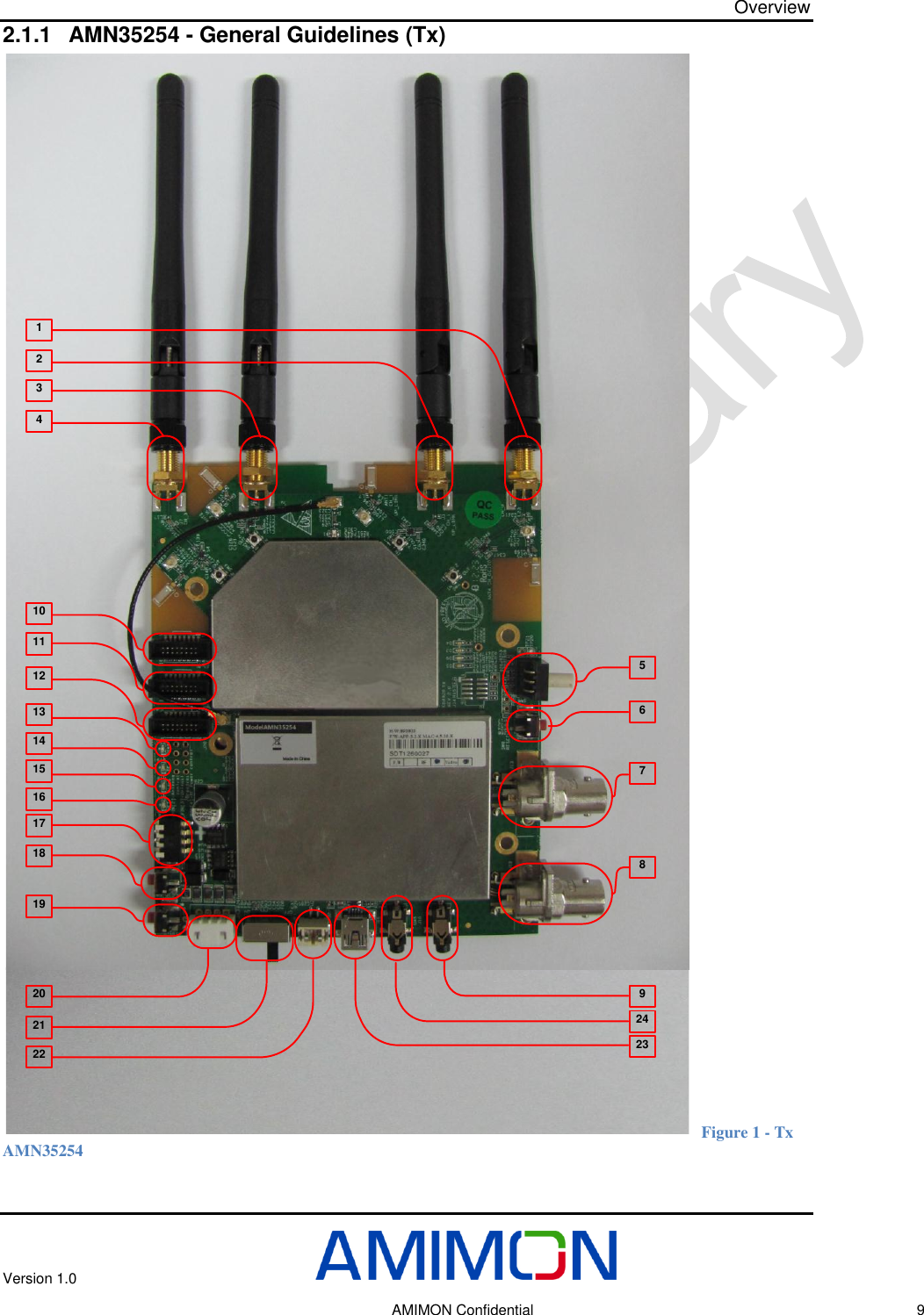
![Overview Version 1.0 AMIMON Confidential 12 2.1.8 Knob - Frequency selection commands The user will be able to select between fixed, non-DFS, frequencies, and automatic mode that will include all frequencies as specified in the table below. Using knob the user will determine on which fixed frequency system will work 1-4, or alternatively system in automatic mode – 5-9, system will hop between different available frequencies. (DFS channels cannot be used as fixed frequencies since system must hop automatically if radar is detected). Table 3 - Frequency selection commands 40MHz Bandwidth Frequency [MHz] US Europe SW Command SW Command 5190 1 1 5230 2 2 5270 Only in Auto mode Only in Auto mode 5310 Only in Auto mode Only in Auto mode 5510 Only in Auto mode Only in Auto mode 5550 Only in Auto mode Only in Auto mode 5590 X Only in Auto mode 5630 X Only in Auto mode 5670 Only in Auto mode Only in Auto mode 5755 3 X 5795 4 X Automatic 5-9 5-9](https://usermanual.wiki/Amimon/AMN35254/User-Guide-1916239-Page-12.png)
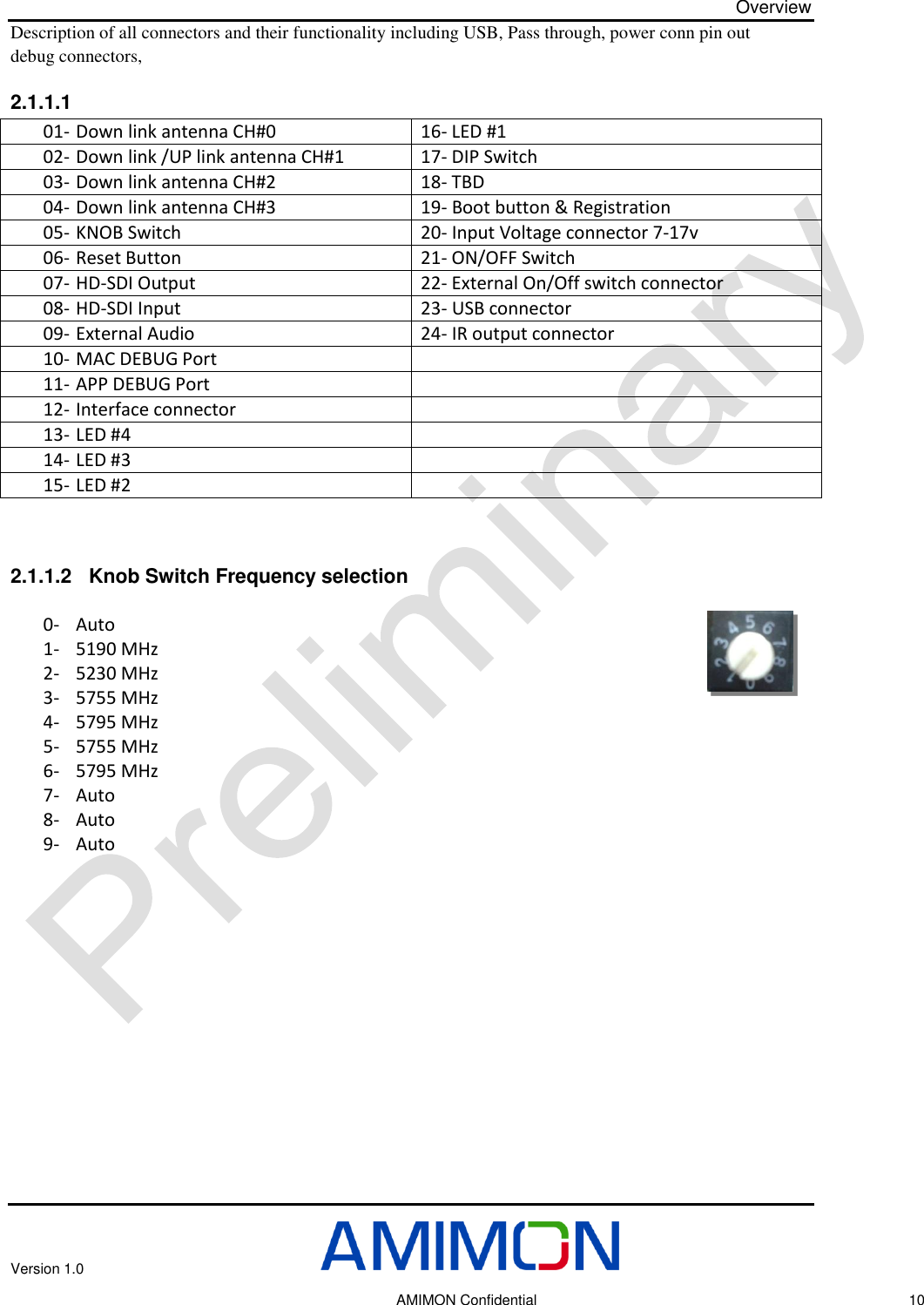
![Overview Version 1.0 AMIMON Confidential 15 SDI RX100 pin BGA, 1 mm pitchD[19:0]DE,HS,VS,CLKI2Sx4STM32103 64 LQFPSPISPI2RSTLOCKCFG[11:0] SPISPI1See default values in the spec27 MHz10 pin connector16 MHzAMN 2120 (BB Tx)FlashSPIMaxim 2850(RFIC Tx)DLI/QULI/Q PAUSBPower7-17VUARTAPP UARTMAC UARTUSBUART40 MHzPASWSPICLKPAPA pass-through outputINPUTLED’s ButtonsLED’sButtonsAudio ADCAudio MuxI2SFrequency Knob Figure 2: TX - AMN35254 BLOCK DIAGRAM](https://usermanual.wiki/Amimon/AMN35254/User-Guide-1916239-Page-15.png)