Amimon AMN35254 HD-SDI wireless transmitter module User Manual
Amimon Ltd. HD-SDI wireless transmitter module
Amimon >
User Manual

Version 1.0
AMIMON Confidential 1
HD-SDI TX
WIRELESS MODULE –
FALCON TX
AMN35254
USER GUIDE 1.0
Version 0.1

Important Notice
Version 1.0
AMIMON Confidential 2
Important Notice
AMIMON Ltd. reserves the right to make corrections, modifications, enhancements, improvements, and other changes to its products and
services at any time and to discontinue any product or service without notice. Customers should obtain the latest relevant information before
placing orders and should verify that such information is current and complete. All products are sold subject to AMIMON's terms and conditions
of sale supplied at the time of order acknowledgment.
AMIMON warrants performance of its hardware products to the specifications applicable at the time of sale in accordance with AMIMON's
standard warranty. Testing and other quality control techniques are used to the extent AMIMON deems necessary to support this warranty.
Except where mandated by government requirements, testing of all parameters of each product is not necessarily performed.
AMIMON assumes no liability for applications assistance or customer product design. Customers are responsible for their products and
applications using AMIMON components. To minimize the risks associated with customer products and applications, customers should provide
adequate design and operating safeguards.
AMIMON does not warrant or represent that any license, either express or implied, is granted under any AMIMON patent right, copyright, mask
work right, or other AMIMON intellectual property right relating to any combination, machine, or process in which AMIMON products or services
are used. Information published by AMIMON regarding third-party products or services does not constitute a license from AMIMON to use such
products or services or a warranty or endorsement thereof. Use of such information may require a license from a third party under the patents
or other intellectual property of the third party, or a license from AMIMON under the patents or other intellectual property of AMIMON.
Reproduction of information in AMIMON data books or data sheets is permissible only if reproduction is without alteration and is accompanied
by all associated warranties, conditions, limitations, and notices. Reproduction of this information with alteration is an unfair and deceptive
business practice. AMIMON is not responsible or liable for such altered documentation.
Resale of AMIMON products or services with statements different from or beyond the parameters stated by AMIMON for that product or service
voids all express and any implied warranties for the associated AMIMON product or service and is an unfair and deceptive business practice.
AMIMON is not responsible or liable for any such statements.
All company and brand products and service names are trademarks or registered trademarks of their respective holders.
Contact Us
US Office
2350 Mission College Blvd.
Suite 500
Santa Clara, CA 95054
Tel: +1 650 641 7178
Israeli Headquarters
2 Maskit St.
Building D, 2nd Floor
P.O.Box 12618
Herzlia 46733, Israel
Tel: +972-9-962-9222
Fax: +972-9-956-5467
contact@amimon.com
Japan Office
FS Building 9F.
1-14-9 Higashi-Gotanda Shinagawa-ku
Tokyo 141-0022,
Japan
TEL +81-3-3444-4305
contact.japan@amimon.com
Revision History
Version 1.0
AMIMON Confidential 3
Revision History
Version
Date
Description
1.0
17 Feb 2013
Initial Release

Table of Contents
Version 1.0
AMIMON Confidential 4
Table of Contents
Important Notice ............................................................................................... 2
Revision History ................................................................................................ 3
Table of Contents .............................................................................................. 4
List of Figures .................................................................................................... 6
List of Tables ..................................................................................................... 6
Chapter 1 7
Introduction ....................................................................................................... 7
Chapter 2 8
Overview 8
2.1 AMN35254 WHDI Source (TX): .................................................................................................................... 8
2.1.1 AMN35254 - General Guidelines (Tx)................................................................................................ 9
2.1.2 LEDs ................................................................................................................................................ 11
2.1.3 On/Off switch .................................................................................................................................... 11
2.1.4 External On/Off switch connector .................................................................................................... 11
2.1.5 Boot button ....................................................................................................................................... 11
2.1.6 Reset button ..................................................................................................................................... 11
2.1.7 Input Voltage connector ................................................................................................................... 11
2.1.8 Knob - Frequency selection commands .......................................................................................... 12
2.1.9 IR blaster .......................................................................................................................................... 13
2.1.10 Audio AUX ........................................................................................................................................ 13
2.1.11 USB .................................................................................................................................................. 13
2.1.12 External On/Off switch connector .................................................................................................... 14
2.1.13 I2C connector ................................................................................................................................... 14
2.2 Antennas ...................................................................................................................................................... 14
2.3 Block diagram of the TX AMN35254 ......................................................................................................... 14


List of Figures
Version 1.0
AMIMON Confidential 6
List of Figures
Figure 1 - Tx AMN35254 ........................................................................................................................................... 9
Figure 2: TX - AMN35254 BLOCK DIAGRAM ............................................................................................................ 15
List of Tables
Table 1: Technical Specifications ............................................................................................................................... 7
Table 2: Transmitter Specifications ........................................................................................................................... 7
Table 3 - Frequency selection commands ............................................................................................................... 12
Version 1.0
AMIMON Confidential 7
Chapter 1
Introduction
The AMN35254 / AMN36254 are respectively wireless A/V transmitter /receiver boards, which works at the
5GHz unlicensed band.
They are based on AMIMON's WHDI Professional chipset that consist of the AMN2220_A4W / AMN2120_A4W
baseband receiver/transmitter and the MAXIM 2851/2850 ICs, presents the ultimate solution for HD-SDI system
into a wireless one. The perfect HD/SD video, audio quality, the high robustness and the invisible latency of the
wireless system are unmatched by any other wireless technology and presents a true alternative to cable. The
WHDI system transmits uncompressed video and audio streams wirelessly and thus simplifies and eliminates
system issues, such as: lip-sync, large buffers and other burdens like retransmissions or error propagation.
System Technical Specifications:
Video Resolution:
1080p/50, 1080p/60, 1080/59.94i, 1080/50i, 1080/29.97p, 1080/23.98p, , 720/59.94p, 720/50p, 525i/59.94, 625i/50, 1080/24p,
1080/24PsF, 1080/23.98PsF,1080/25PsF
Frequencies:
Non-DFS Frequencies:
5.15 ~ 5.25 GHz
5.725~5.825 GHz
DFS Frequencies:
5.25 ~ 5.35 GHz
5.47 ~ 5.725 GHz
Video Interface:
SDI with automatic detection (SD,HD and 3G) over 75 Ohm BNC.
Environment:
Operational - 0:40° C, 10%~90% humidity
Storage - 0:55° C, 10%~90% humidity
Range:
Up to 50m line of sight.
Audio:
Over SDI
Table 1: Technical Specifications
Transmitter Specifications:
Transmitter AMN35254
Video Interface:
SDI pass through
(Option to connect external connector board)
Frequency Control:
Analog knob with 4 manual fix (non DFS) frequencies and one for
automatic frequency selection mode (included DFS).
Antenna:
3 transmitting+ 1 transmitting /Receiving
Voltage:
7-17 V
Size:
(L)130mm x (W)106mm x (H) 16mm
User Control:
3 LEDs indicating Power, Video lock and Network lock
USB connector for software update
Hidden button for registration
Reset button
Table 2: Transmitter Specifications

Overview
Version 1.0
AMIMON Confidential 8
Chapter 2
Overview
2.1 AMN35254 WHDI Source (TX):
The AMN35254 WHDI Source is designed to modulate and transmit downstream video and audio
content over the wireless medium and receive a control channel over the wireless upstream. The
modulation uses a 40 MHz bandwidth and is carried over the 5GHz unlicensed band. Fig 2 shows a
block diagram of the AMN35254. The HD-SDI input is connected to the Gennum SDI 2971A which
converts the SDI signal to A/V digital bus that is connected to the AMN2120 baseband transmitter.
It has a MIMO design of four wireless output channels and one input channel. The internal
microcontroller (STM32103) is responsible for control and management.
The ST STM32F103 application microcontroller controls the SDI chip and the baseband AMN2120
chip using SPI standard bus. The application microcontroller provides USB device interface through
a mini USB connector.
Overview
Version 1.0
AMIMON Confidential 9
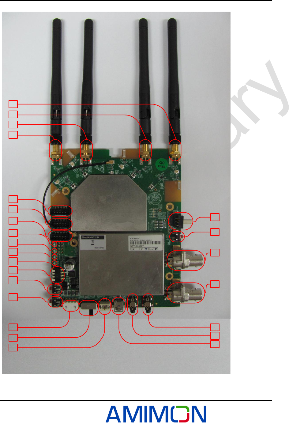
2.1.1 AMN35254 - General Guidelines (Tx)
1
4
3
2
10
11
12
13
14
15
16
17
18
19
20
21
22
5
6
7
8
9
24
23
Figure 1 - Tx
AMN35254
Overview
Version 1.0
AMIMON Confidential 10
Description of all connectors and their functionality including USB, Pass through, power conn pin out
debug connectors,
2.1.1.1
01- Down link antenna CH#0
16- LED #1
02- Down link /UP link antenna CH#1
17- DIP Switch
03- Down link antenna CH#2
18- TBD
04- Down link antenna CH#3
19- Boot button & Registration
05- KNOB Switch
20- Input Voltage connector 7-17v
06- Reset Button
21- ON/OFF Switch
07- HD-SDI Output
22- External On/Off switch connector
08- HD-SDI Input
23- USB connector
09- External Audio
24- IR output connector
10- MAC DEBUG Port
11- APP DEBUG Port
12- Interface connector
13- LED #4
14- LED #3
15- LED #2
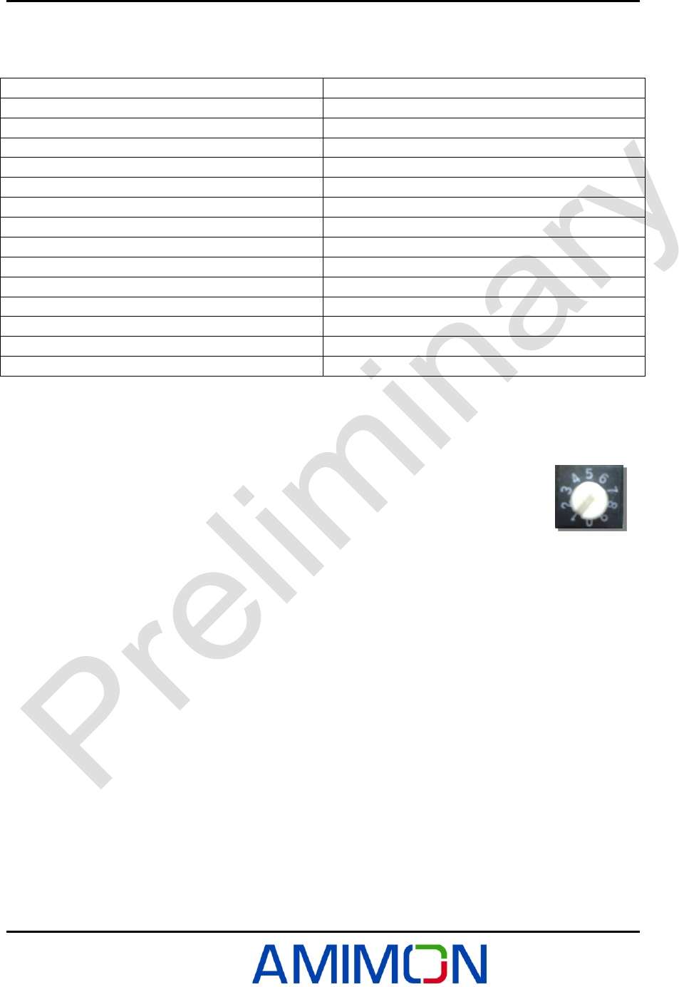
2.1.1.2 Knob Switch Frequency selection
0- Auto
1- 5190 MHz
2- 5230 MHz
3- 5755 MHz
4- 5795 MHz
5- 5755 MHz
6- 5795 MHz
7- Auto
8- Auto
9- Auto
Overview
Version 1.0
AMIMON Confidential 11
2.1.2 LEDs
1- D20 - Power - on/off
2- D19 - Video Lock (SDI locked) - on/off
3- D18 - Network (link to Rx) - on/off
4- D17 - (TBD)
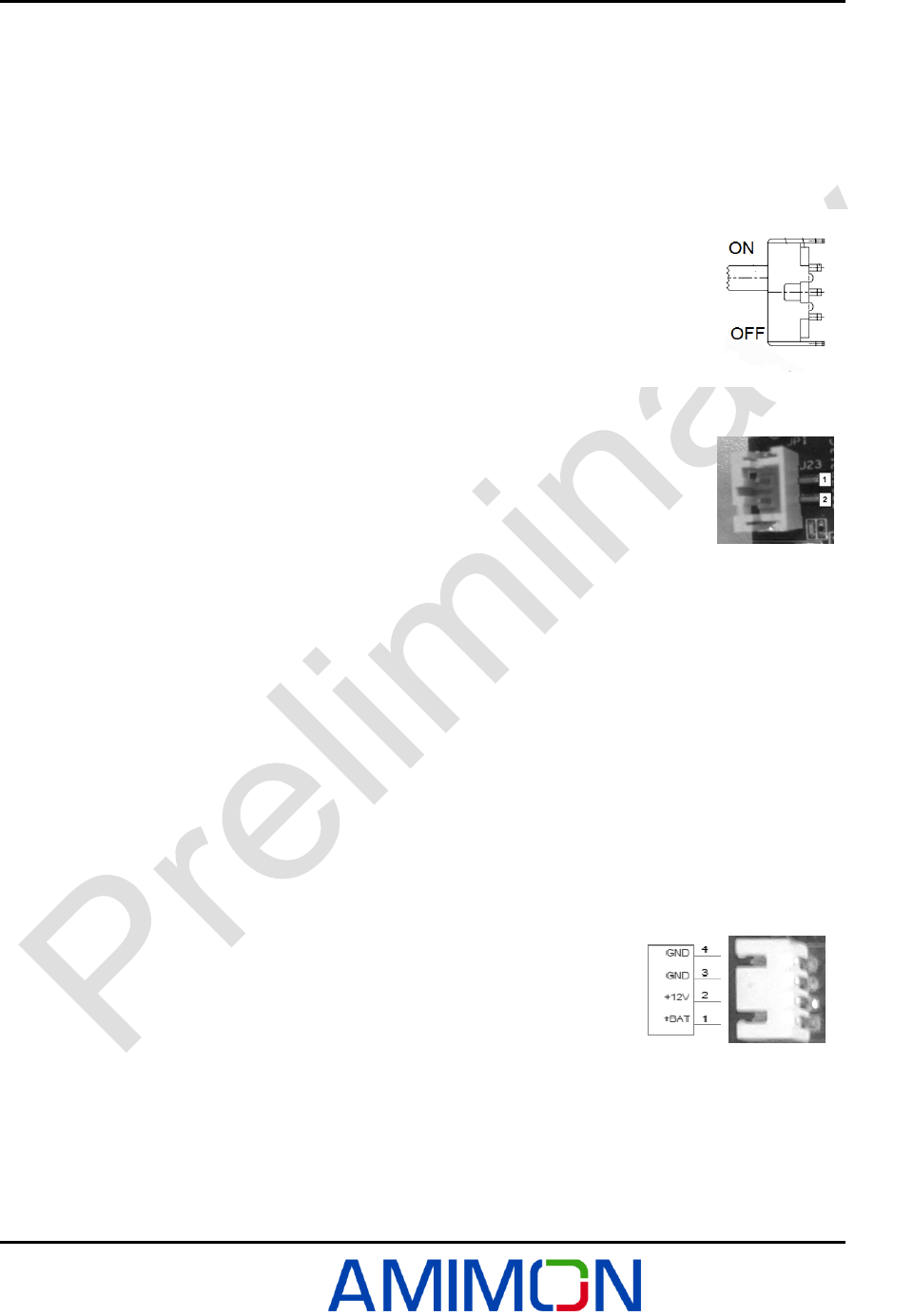
2.1.3 On/Off switch
System has a main switch that turns on and off.
The system is active when the switch is near J1(voltage input connector)
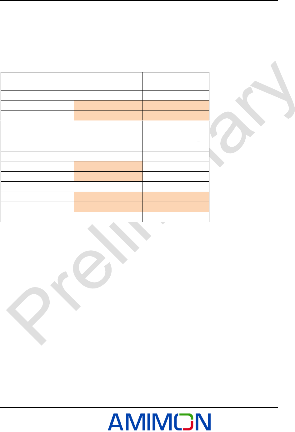
2.1.4 External On/Off switch connector
This connector is used for external On/Off switch. Pin 1 is VDD, Pin 2 is
Power Enable.
2.1.5 Boot button
Boot mode is a technical mode. In order to operate this mode you should hold "Boot
button" for 5 seconds, when the system wakes up (press on the "Boot button" and
then press on the "Reset button").
2.1.6 Reset button
The "Reset button" clears the dynamic memory and reboots the system.
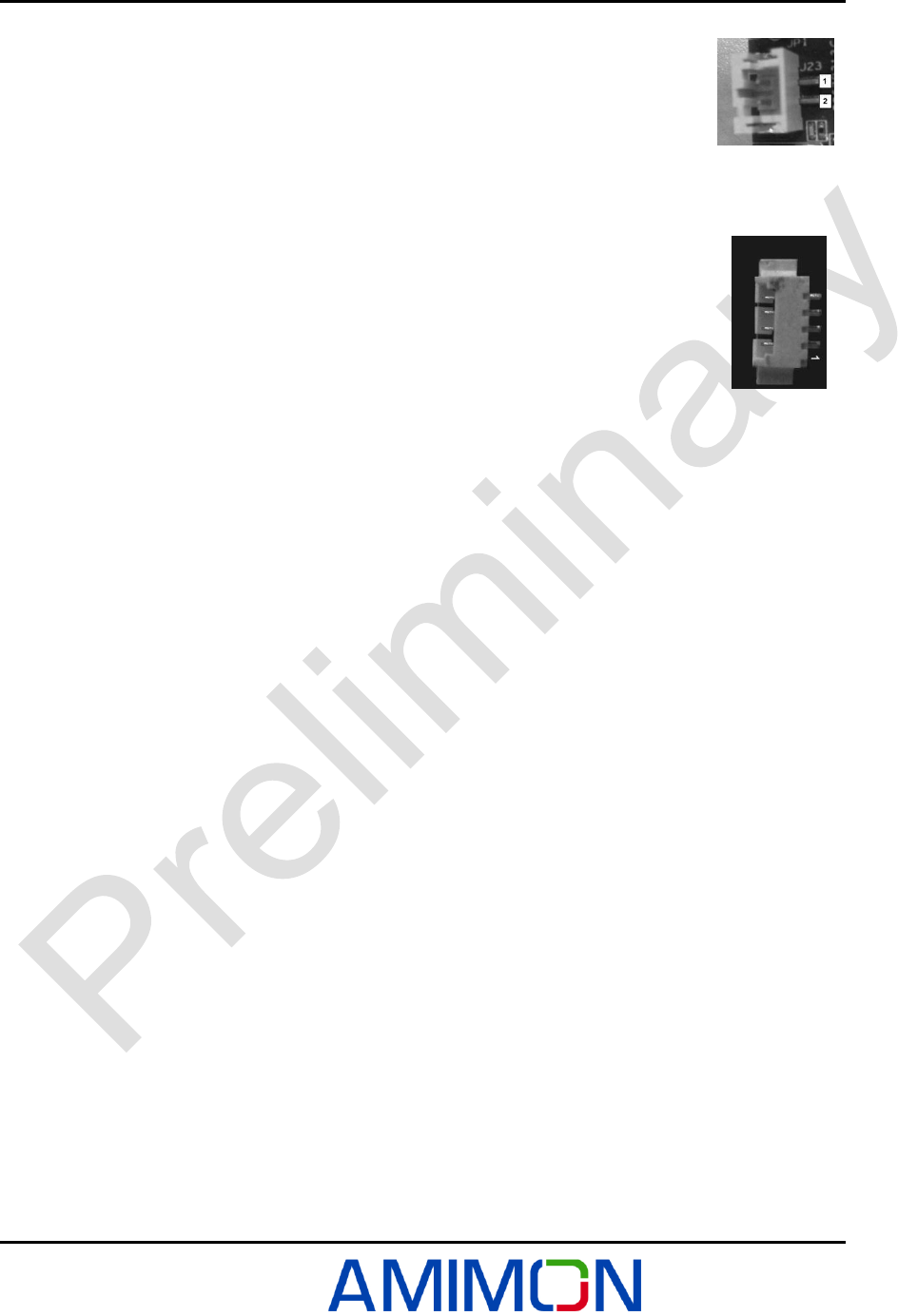
2.1.7 Input Voltage connector
Input voltage connector contains 4 pins,
1- +BAT.
2- Power supply.
3- GND.
4- GND.
Overview
Version 1.0
AMIMON Confidential 12
2.1.8 Knob - Frequency selection commands
The user will be able to select between fixed, non-DFS, frequencies, and automatic mode that will
include all frequencies as specified in the table below. Using knob the user will determine on which
fixed frequency system will work 1-4, or alternatively system in automatic mode – 5-9, system will
hop between different available frequencies. (DFS channels cannot be used as fixed frequencies
since system must hop automatically if radar is detected).
Table 3 - Frequency selection commands
40MHz Bandwidth
Frequency [MHz]
US
Europe
SW Command
SW Command
5190
1
1
5230
2
2
5270
Only in Auto mode
Only in Auto mode
5310
Only in Auto mode
Only in Auto mode
5510
Only in Auto mode
Only in Auto mode
5550
Only in Auto mode
Only in Auto mode
5590
X
Only in Auto mode
5630
X
Only in Auto mode
5670
Only in Auto mode
Only in Auto mode
5755
3
X
5795
4
X
Automatic
5-9
5-9
Overview
Version 1.0
AMIMON Confidential 13
2.1.9 IR blaster
AMN35254 support PWM interface to IR blaster via audio 2.5mm jack, for
mechanical dimensions of the audio jack follow the datasheet
http://www.cui.com/pdffiles/SJ-2523-SMT.pdf , Silk number: J15.
2.1.10 Audio AUX
The External audio connected via 2.5mm jack, for mechanical dimensions of the
audio jack follow the datasheet http://www.cui.com/pdffiles/SJ-2523-SMT.pdf ,
Silk number: J16.
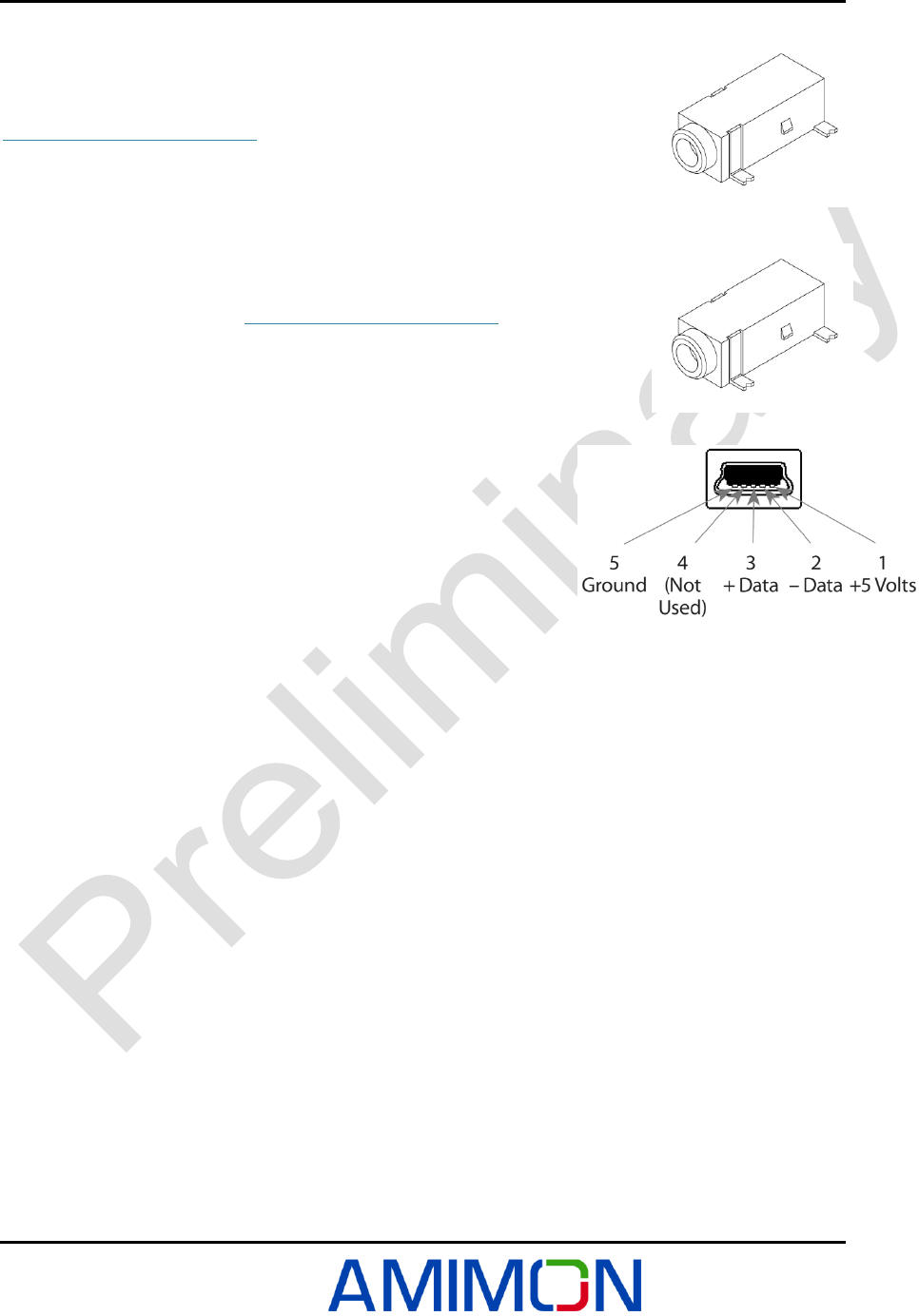
2.1.11 USB
There is a USB connector on board that is connected to the application
uC.
This will be used for software upgrade through WHDI monitor.
USB type: USB mini-B connector, Silk number J18.
Overview
Version 1.0
AMIMON Confidential 14
2.1.12 External On/Off switch connector
This connector is used for external On/Off switch, Pin 1 is VDD, Pin 2 is
Power Enable.
2.1.13 I2C connector
I2C Host interface connector is used for transferring I2C protocol message between
the host chip (Micro Controller STM32F103) and the slave component.
Pin-1: 3.3v, Pin–2: SCL Pin–3: SDA Pin-4: GND
2.2 Antennas
This module is authorized to use only with the RP-SMA external antennas with 5dBi gain or less.
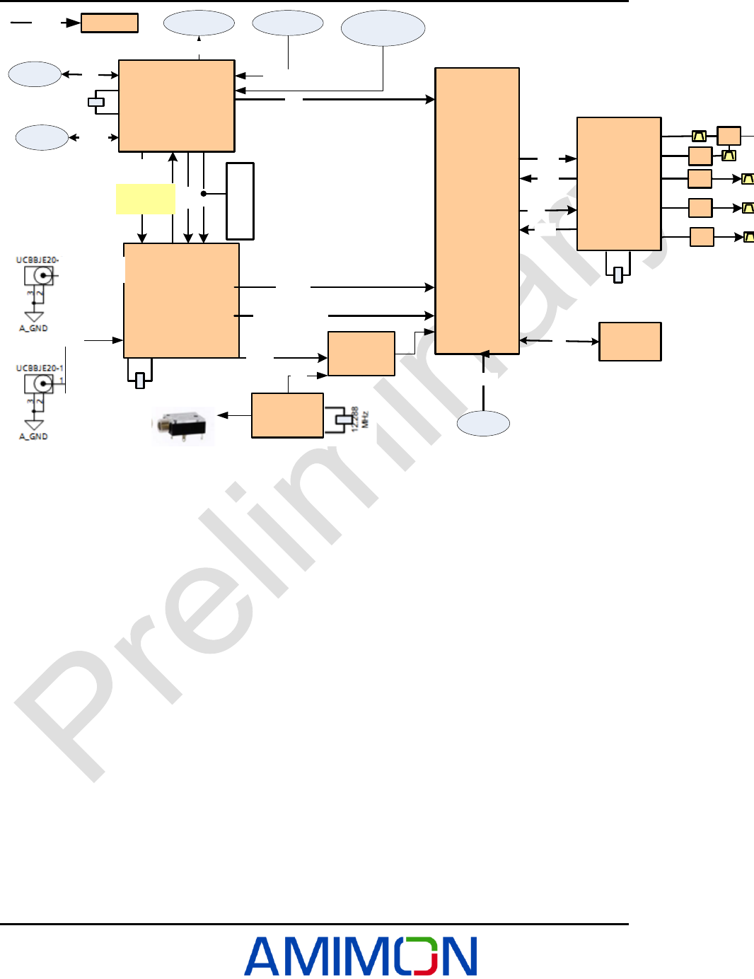
2.3 Block diagram of the TX AMN35254
Overview
Version 1.0
AMIMON Confidential 15
SDI RX
100 pin BGA, 1 mm
pitch
D[19:0]
DE,HS,VS,CLK
I2Sx4
STM32103
64 LQFP
SPI
SPI2
RST
LOCK
CFG[11:0]
SPI
SPI1
See default
values
in the spec
27 MHz
10 pin
connector
16 MHz
AMN 2120
(BB Tx)
Flash
SPI
Maxim 2850
(RFIC Tx)
DLI/Q
ULI/Q PA
USB
Power
7-17V
UART
APP
UART
MAC
UART
USB
UART
40 MHz
PA
S
W
SPI
CLK
PA
PA
pass-through
output
INPUT
LED’s Buttons
LED’s
Buttons
Audio ADC
Audio Mux
I2S
Frequency
Knob
Figure 2: TX - AMN35254 BLOCK DIAGRAM

FCC Caution
Version 1.0
AMIMON Confidential 16
Chapter 3
FCC Caution
Any changes or modifications not expressly approved by the responsible party could void the user's authority to operate
this equipment.
Notice:
This module in its final integration requires the end-product to continue to comply with DFS requirements.
A class II permissive change may be required for operation not already described in the FCC Grant filing.
OEM Labeling Requirements
Notice: The OEM of final integrator must ensure that FCC labeling requirements are met.
For a host using this module, if (1) the module’s FCC ID is not visible when installed in the host, or (2) if the host is
marketed so that end users do not have straightforward commonly used methods for access to remove the module so that
the FCC ID of the module is visible; then an additional permanent label referring to the enclosed module should be used,
with the following contents:
The host OEM user manual must also contain clear instructions on how end users can find and/or access the module and
the FCC ID.
The applicable usage is to be used as a wireless device, connected to the back of a professional camera and transmitting live
video, coming from BNC connectors
NOTE:
This equipment has been tested and found to comply with the limits for a Class B digital device, pursuant to part 15 of the
FCC Rules. These limits are designed to provide reasonable protection against harmful interference in a residential
installation. This equipment generates, uses and can radi-ate radio frequency energy and, if not in-stalled and used in
accordance with the instructions, may cause harmful interference to radio communications. However, there is no
guarantee that interference will not occur in a particular installation.
FCC Radiation Exposure Statement
This equipment complies with FCC RF radiation exposure limits set forth for an uncontrolled environment.
This transmitter must not be co-located or operating in conjunction with any other antenna or transmitter.
This equipment complies with Part 15 of the FCC Rules. Operation is subject to the following two conditions:
(1) This device may not cause harmful interference, and
(2) This device must accept any interference received, including interference that may cause undesired operation.
The antenna used for transmission must be installed to provide a separation distance of at least 20cm from all persons
and must not be co-located or operating in conjunction with any other antenna or transmitter
.
Company Name
MODEL:
Contains Model: AMN35254, FCC ID:VQSAMN35254
This device complies with Part 15 of the FCC Rules. Operation is subject to the following two conditions:
(1) This device may not cause harmful interferences, and
(2) This device must accept any interference received, including interference that may cause undesired operation.

FCC Caution
Version 1.0
AMIMON Confidential 17