Amimon AMN36254 HD-SDI wireless receiver module User Manual
Amimon Ltd. HD-SDI wireless receiver module
UserManual.wiki
>
Amimon
>
AMN36254 User Manual
User Manual
Navigation menu
Upload a User Manual
Namespaces
Wiki Guide
HTML
PDF
Info
Views
User Manual
Discussion / Help
Navigation
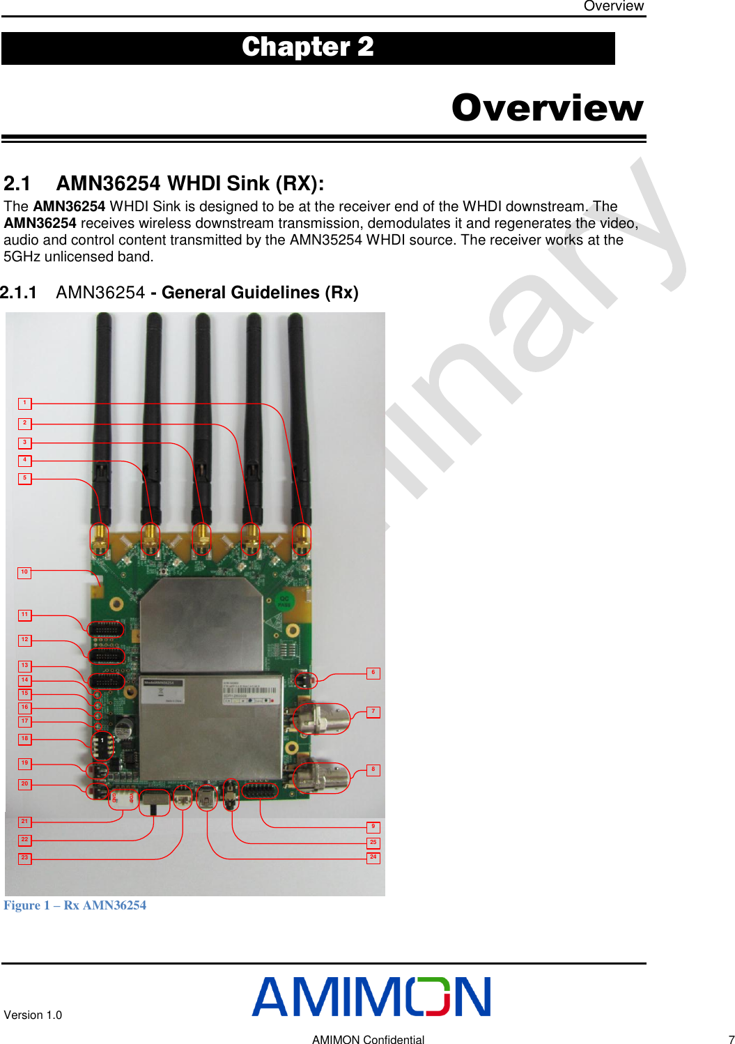
![Overview Version 1.0 AMIMON Confidential 11 2.1.10 External On/Off switch connector This connector is used for external On/Off switch, Pin 1 is VDD, Pin 2 is Power Enable. 2.1.11 I2C connector I2C Host interface connector is used for transferring I2C protocol message between the host chip (Micro Controller STM32F103) and the slave component. Pin-1: 3.3v, Pin–2: SCL Pin–3: SDA Pin-4: GND 2.2 Antennas This module is authorized to be used only with the RP-SMA external antennas with 5dBi gain or less. The module also use 2dBi chip antenna for reception only. 2.3 Block Diagram Figure 2 – Block Diagram AMN 2220 (BB Rx)FlashSPIMaxim 2851(RFIC Rx)DLI/QULI/QPADDRAiroha 7230USBPower7-17VYCbCr[29:0]HS,VS,DE,DCLKUARTAPP UARTI2SMAC UARTUSBSTM32F103 UARTSPIRST RSTINTMaster SlaveFPGA2972YCbCr[19:0]SDISPI, CFGJTAGSDIButtonsLEDs](https://usermanual.wiki/Amimon/AMN36254/User-Guide-1916790-Page-11.png)