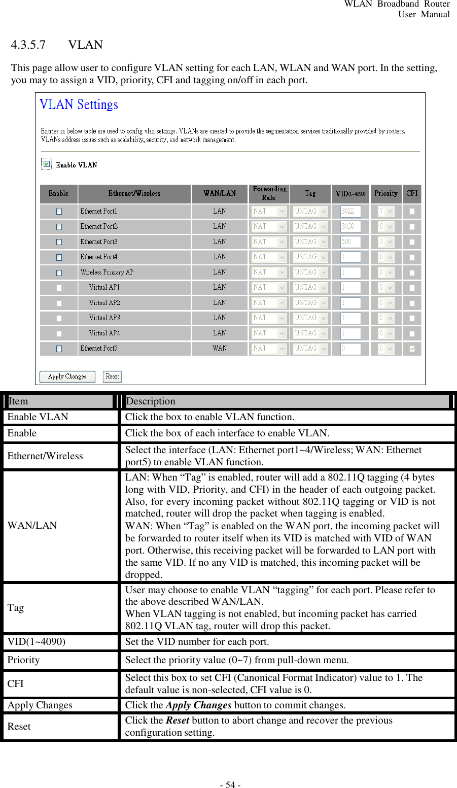
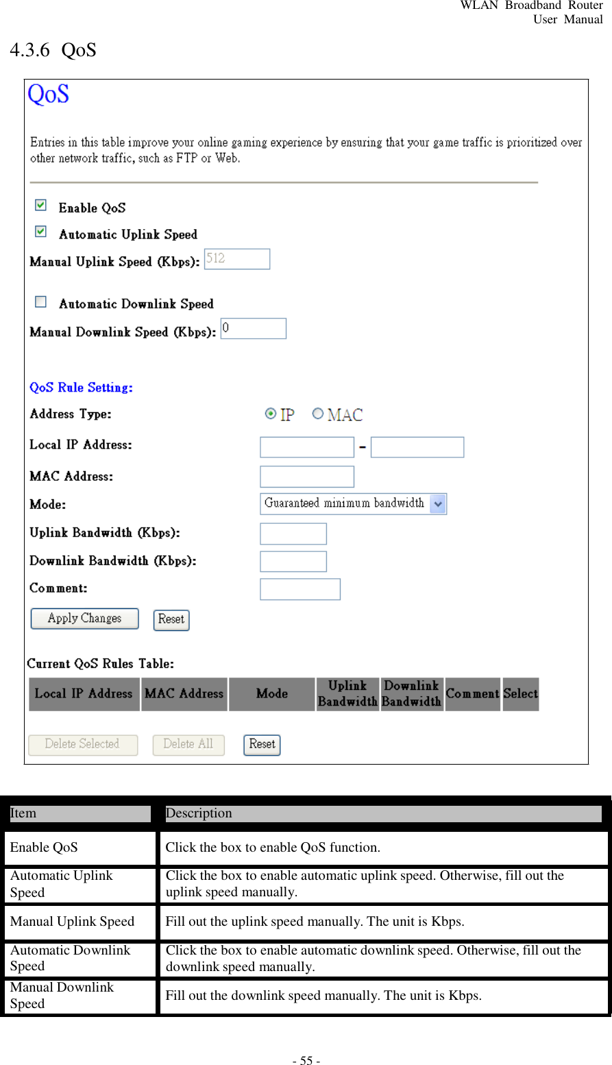
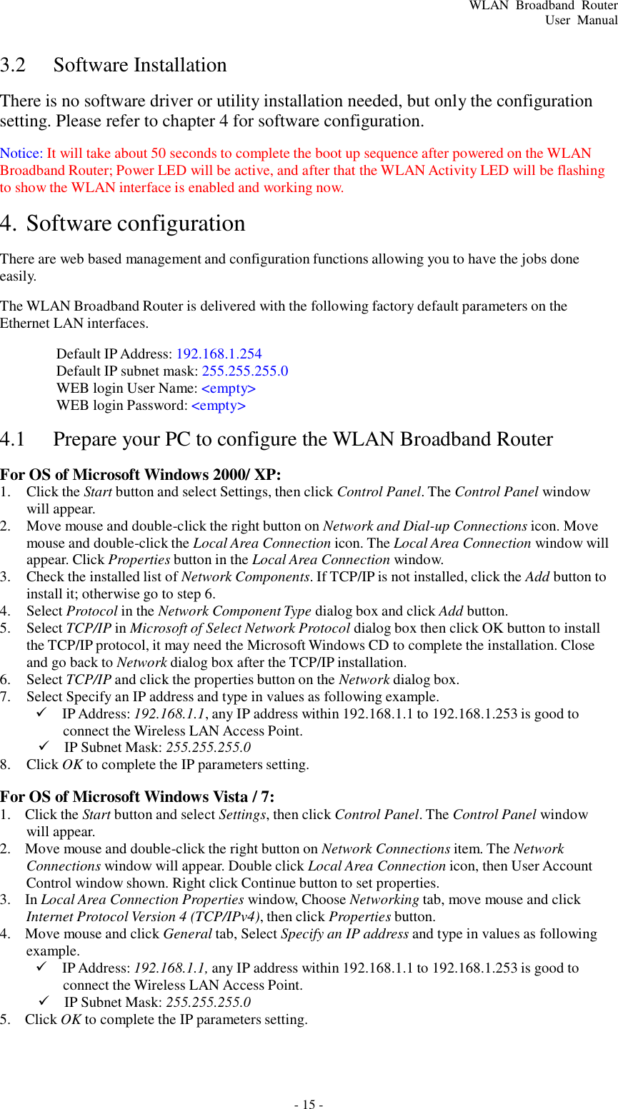
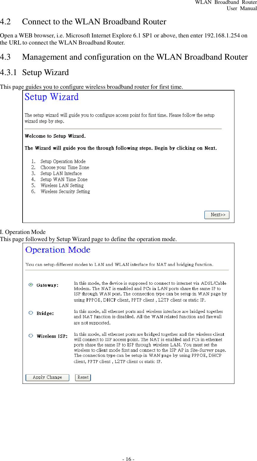
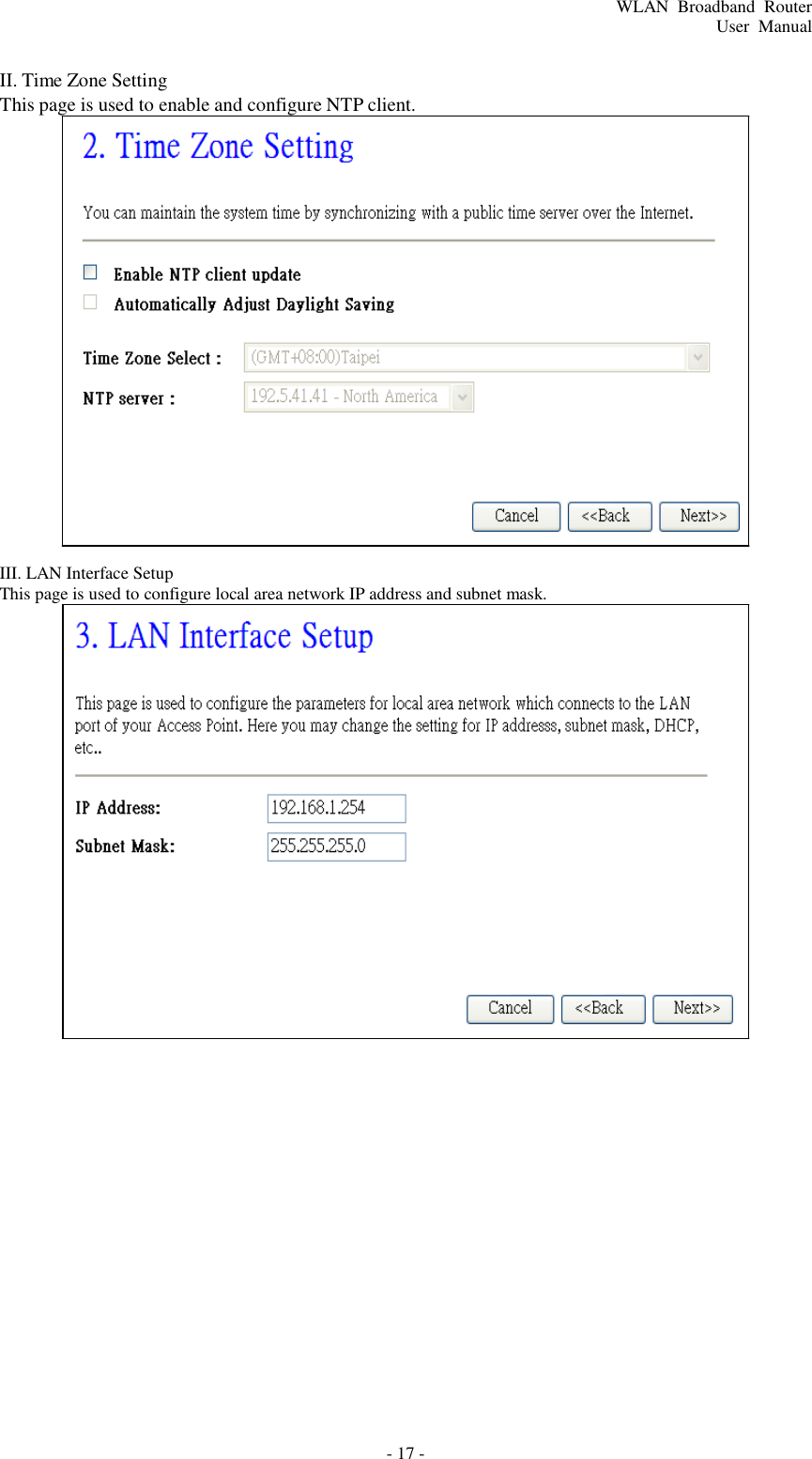
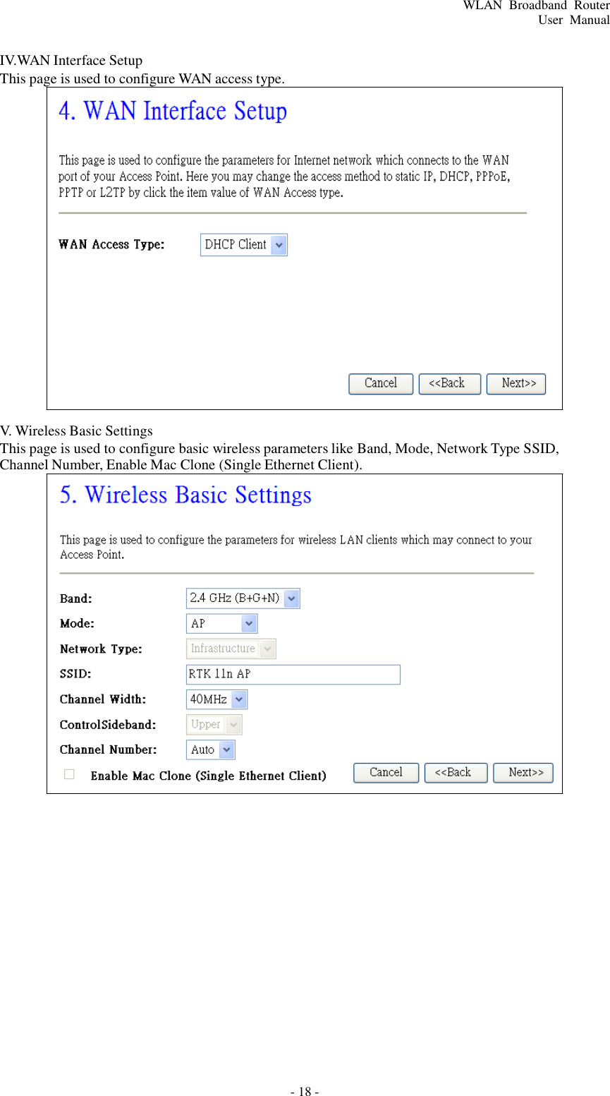
Amped Wireless SR600EX High Power Wireless-N 600mW Pro Smart Repeater User Manual 1
Amped Wireless High Power Wireless-N 600mW Pro Smart Repeater 1
UserManual.wiki
>
Amped Wireless
>
SR600EX User Manual
user manual
Navigation menu
Upload a User Manual
Namespaces
Wiki Guide
HTML
PDF
Info
Views
User Manual
Discussion / Help
Navigation
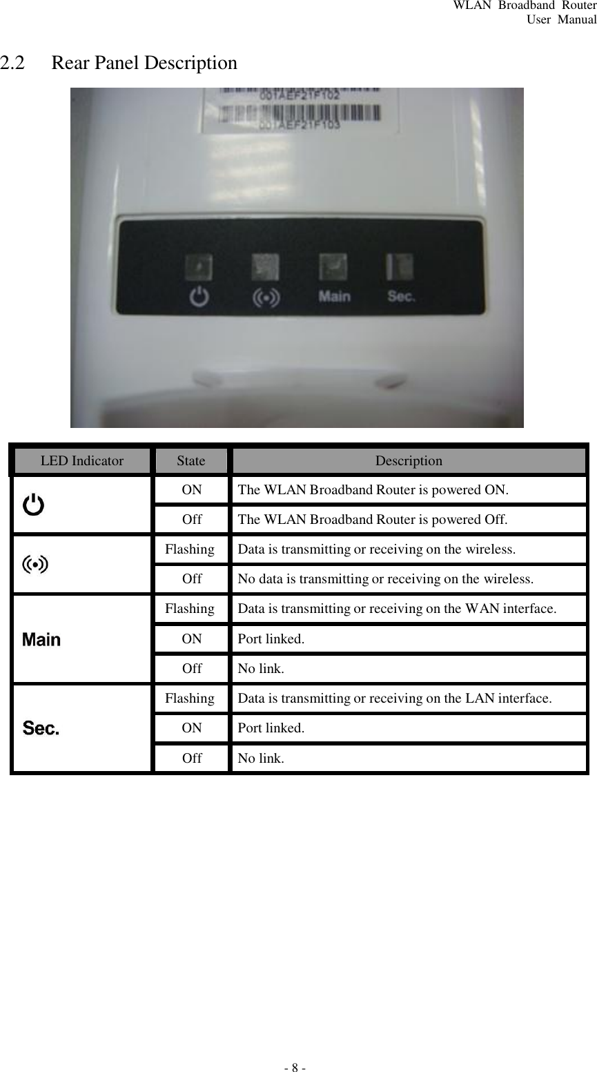
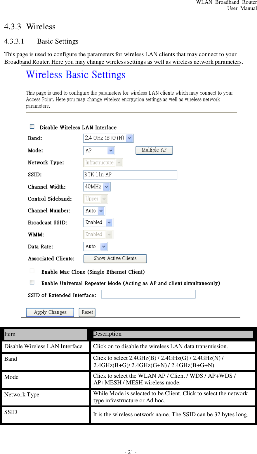
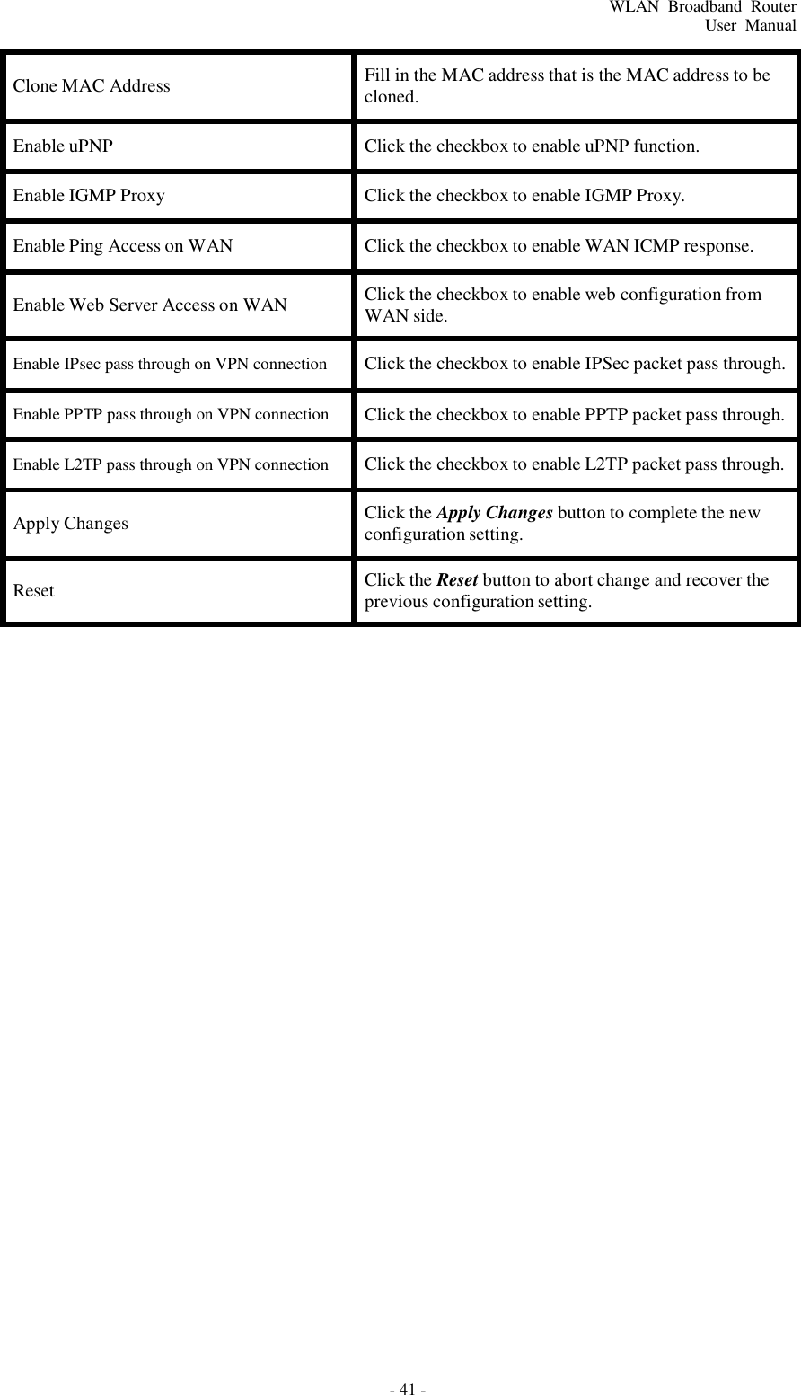
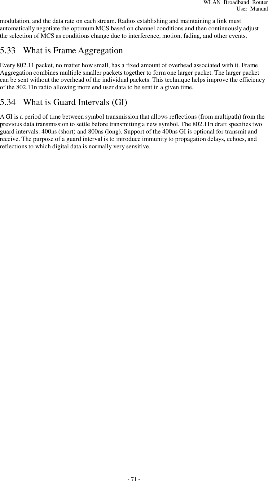
![- 22 - WLAN Broadband Router User Manual Channel Width Select the operating channel width 20 MHz or 40 MHz. [N band only] Control Sideband Select the Sideband with Upper or Lower for channel width 40MHz. [N band only] Channel Number Select the wireless communication channel from pull-down menu. Broadcast SSID Click to enable or disable the SSID broadcast function. WMM Click Enabled/Disabled to init WMM feature. Data Rate Select the transmission data rate from pull-down menu. Data rate can be auto-select, 1M to 54Mbps or MCS. Associated Clients Click the Show Active Clients button to open Active Wireless Client Table that shows the MAC address, transmit-packet, receive-packet and transmission-rate for each associated wireless client. Enable Mac Clone (Single Ethernet Client) Take Laptop NIC MAC address as wireless client MAC address. [Client Mode only] Enable Universal Repeater Mode Click to enable Universal Repeater Mode SSID of Extended Interface Assign SSID when enables Universal Repeater Mode. Apply Changes Click the Apply Changes button to complete the new configuration setting. Reset Click the Reset button to abort change and recover the previous configuration setting.](https://usermanual.wiki/Amped-Wireless/SR600EX/User-Guide-1614037-Page-22.png)
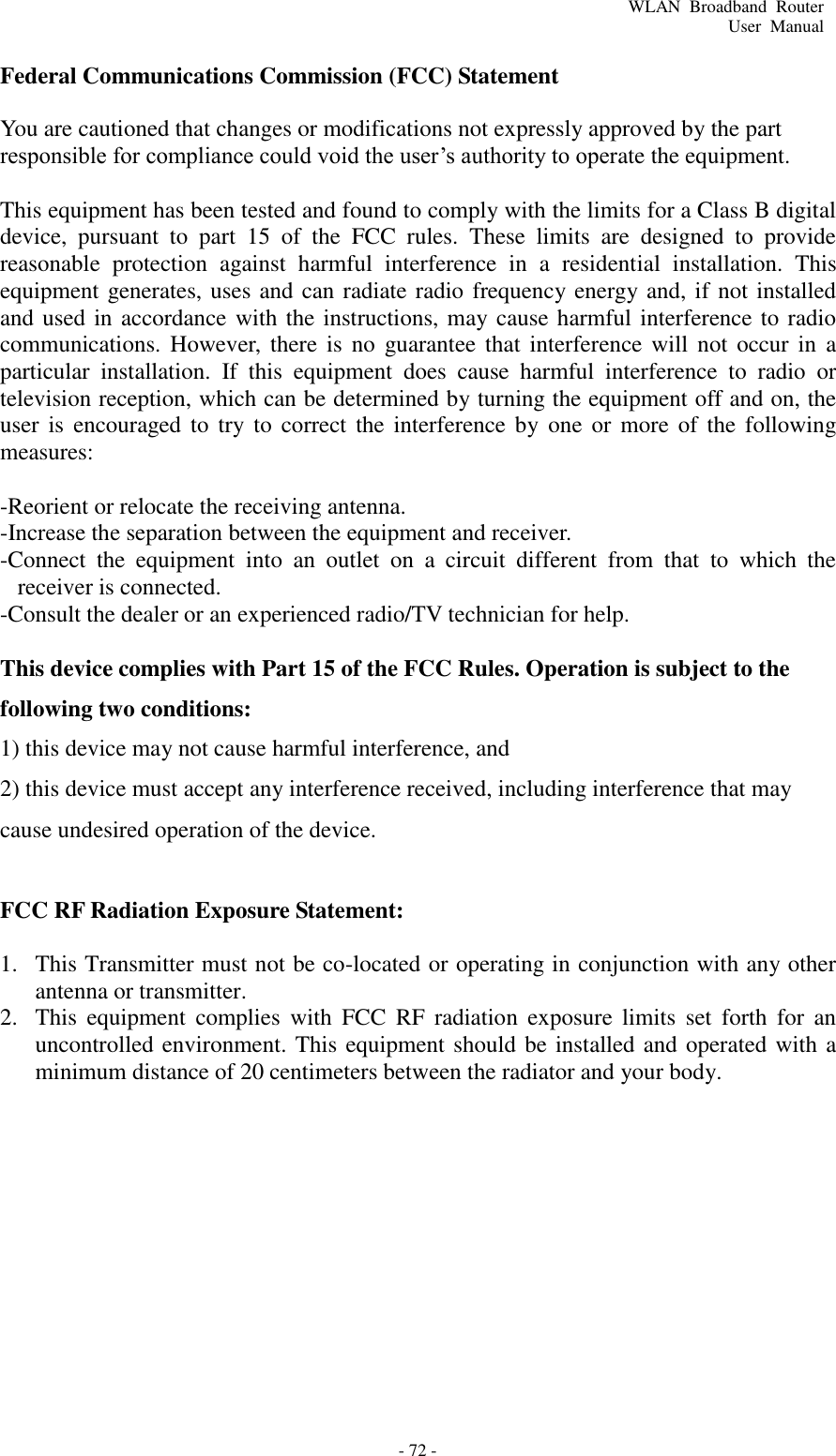
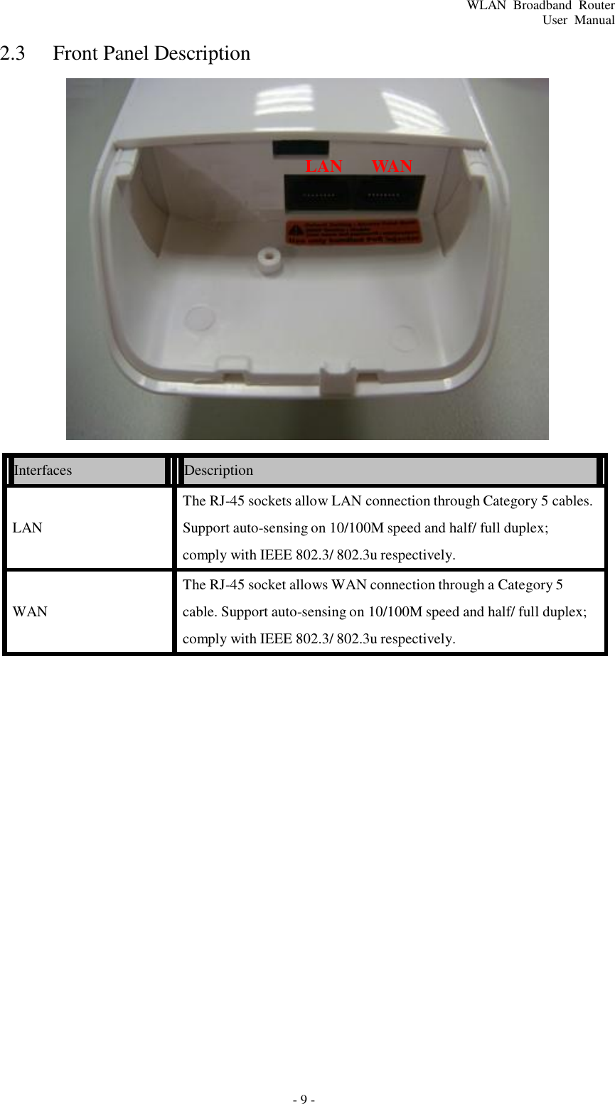
![- 26 - WLAN Broadband Router User Manual 4.3.3.3.3 WPA Item Description Select SSID Select the SSID from multiple APs. WPA Select the “WPA” to enable WPA encryption for wireless security. Authentication Mode While Encryption is selected to be WPA. Click to select the WPA Authentication Mode with Enterprise (RADIUS) or Personal (Pre-Shared Key). WPA Cipher Suite Select the Cipher Suite for WPA encryption. While Encryption is selected to be WPA. Select the Pre-shared key Pre-Shared Key Format format from the pull-down menu. The format can be Passphrase or Hex (64 characters). [WPA, Personal(Pre-Shared Key) only] Pre-Shared Key Fill in the key value. [WPA, Personal(Pre-Shared Key) only] RADIUS Server IP Address Fill in the IP address of RADIUS Server. [WPA, Enterprise(RADIUS) only] RADIUS Server Port Fill in the port number for authentication with RADIUS Server. [WPA, Enterprise(RADIUS) only] RADIUS Server Password Fill in the password for authentication with RADIUS Server. [WPA, Enterprise(RADIUS) only] Apply Changes Click the Apply Changes button to complete the new configuration setting. Reset Click the Reset button to abort change and recover the previous configuration setting.](https://usermanual.wiki/Amped-Wireless/SR600EX/User-Guide-1614037-Page-26.png)
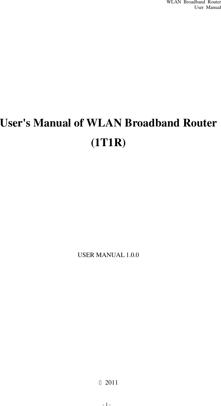
![- 27 - WLAN Broadband Router User Manual 4.3.3.3.4 WPA2 Item Description Select SSID Select the SSID from multiple APs. WPA2 Select the “WPA2” to enable WPA2 encryption for wireless security. Authentication Mode While Encryption is selected to be WPA. Click to select the WPA Authentication Mode with Enterprise (RADIUS) or Personal (Pre-Shared Key). WPA2 Cipher Suite Select the Cipher Suite for WPA2 encryption. While Encryption is selected to be WPA. Select the Pre-shared key Pre-Shared Key Format format from the pull-down menu. The format can be Passphrase or Hex (64 characters). [WPA, Personal(Pre-Shared Key) only] Pre-Shared Key Fill in the key value. [WPA, Personal(Pre-Shared Key) only] RADIUS Server IP Address Fill in the IP address of RADIUS Server. [WPA, Enterprise(RADIUS) only] RADIUS Server Port Fill in the port number for authentication with RADIUS Server. [WPA, Enterprise(RADIUS) only] RADIUS Server Password Fill in the password for authentication with RADIUS Server. [WPA, Enterprise(RADIUS) only] Apply Changes Click the Apply Changes button to complete the new configuration setting. Reset Click the Reset button to abort change and recover the previous configuration setting.](https://usermanual.wiki/Amped-Wireless/SR600EX/User-Guide-1614037-Page-27.png)
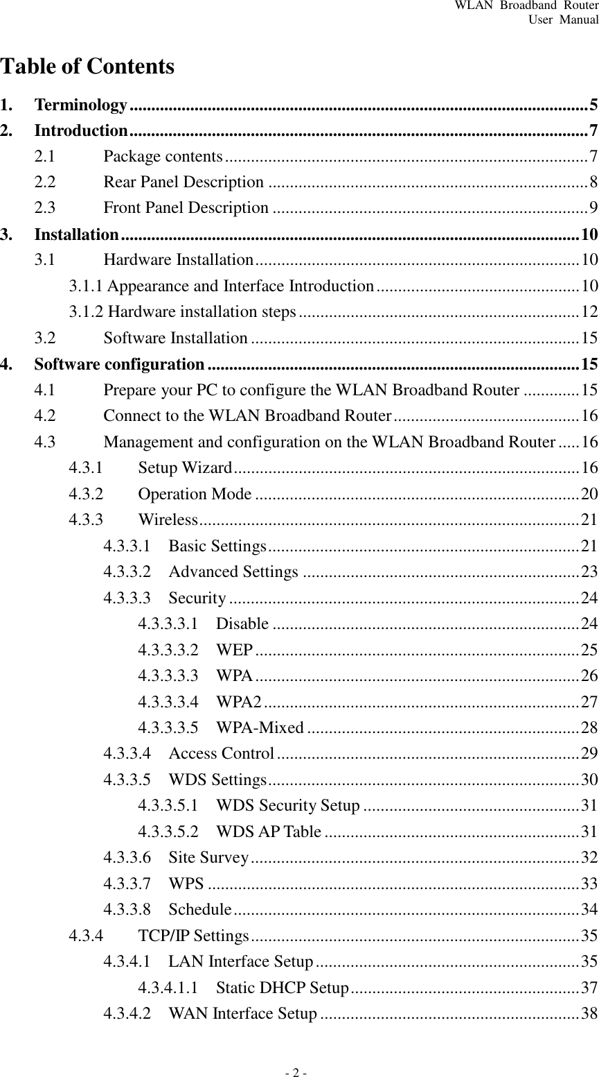
![- 28 - WLAN Broadband Router User Manual 4.3.3.3.5 WPA-Mixed Item Description Select SSID Select the SSID from multiple APs. WPA-Mixed Select the “WPA-Mixed” to enable WPA-Mixed encryption for wireless security. While Encryption is selected to be WPA. Click to select the WPA Authentication Mode Authentication Mode with Enterprise (RADIUS) or Personal (Pre-Shared Key). WPA Cipher Suite Select the Cipher Suite for WPA encryption. WPA2 Cipher Suite Select the Cipher Suite for WPA2 encryption. While Encryption is selected to be WPA. Select the Pre-shared key Pre-Shared Key Format format from the pull-down menu. The format can be Passphrase or Hex (64 characters). [WPA, Personal(Pre-Shared Key) only] Pre-Shared Key Fill in the key value. [WPA, Personal(Pre-Shared Key) only] RADIUS Server IP Address Fill in the IP address of RADIUS Server. [WPA, Enterprise(RADIUS) only] RADIUS Server Port Fill in the port number for authentication with RADIUS Server. [WPA, Enterprise(RADIUS) only] RADIUS Server Password Fill in the password for authentication with RADIUS Server. [WPA, Enterprise(RADIUS) only] Apply Changes Click the Apply Changes button to complete the new configuration setting. Reset Click the Reset button to abort change and recover the previous configuration setting.](https://usermanual.wiki/Amped-Wireless/SR600EX/User-Guide-1614037-Page-28.png)
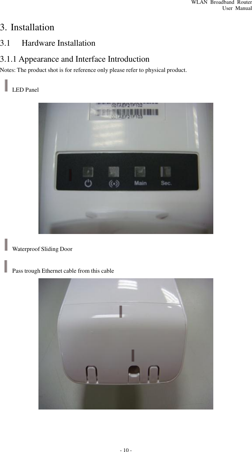
![- 31 - WLAN Broadband Router User Manual 4.3.3.5.1 WDS Security Setup Requirement: Set [Wireless]->[Basic Settings]->[Mode]->AP+WDS This page is used to configure the wireless security between APs. 4.3.3.5.2 WDS AP Table This page is used to show WDS statistics. Item Description MAC Address It shows the MAC Address within WDS. Tx Packets It shows the statistic count of sent packets on the wireless LAN interface. Tx Errors It shows the statistic count of error sent packets on the Wireless LAN interface. Rx Packets It shows the statistic count of received packets on the wireless LAN interface. Tx Rare (Mbps) It shows the wireless link rate within WDS. Refresh Click to refresh the statistic counters on the screen. Close Click to close the current window.](https://usermanual.wiki/Amped-Wireless/SR600EX/User-Guide-1614037-Page-31.png)
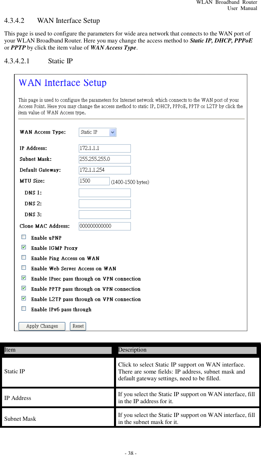
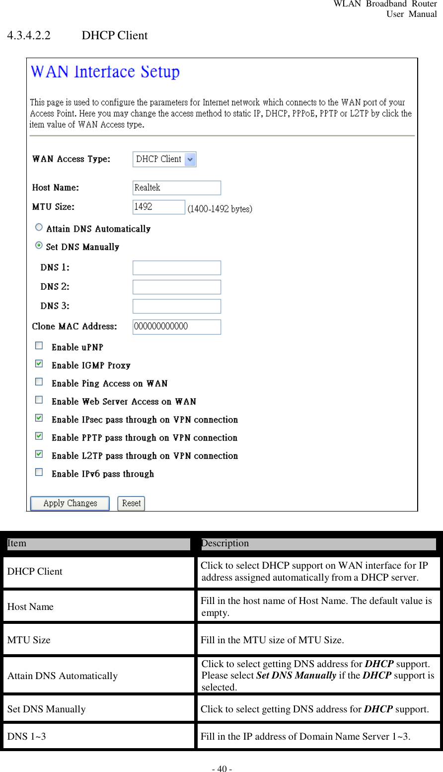
![- 35 - WLAN Broadband Router User Manual 4.3.4 TCP/IP Settings 4.3.4.1 LAN Interface Setup This page is used to configure the parameters for local area network that connects to the LAN ports of your WLAN Broadband Router. Here you may change the setting for IP address, subnet mask, DHCP, etc. Item Description IP Address Fill in the IP address of LAN interfaces of this WLAN Access Point. Subnet Mask Fill in the subnet mask of LAN interfaces of this WLAN Access Point. Default Gateway Fill in the default gateway for LAN interfaces out going data packets. DHCP Click to select Disabled, Client or Server in different operation mode of wireless Access Point. DHCP Client Range Fill in the start IP address and end IP address to allocate a range of IP addresses; client with DHCP function set will be assigned an IP address from the range. Show Client Click to open the Active DHCP Client Table window that shows the active clients with their assigned IP address, MAC address and time expired information. [Server mode only]](https://usermanual.wiki/Amped-Wireless/SR600EX/User-Guide-1614037-Page-35.png)
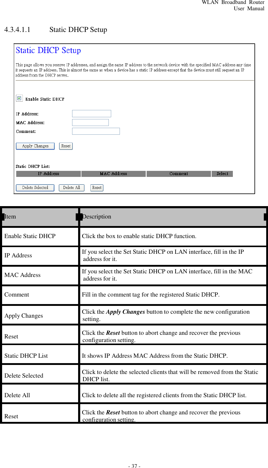
![- 36 - WLAN Broadband Router User Manual Set Static DHCP Manual setup Static DHCP IP address for specific MAC address. [Server mode only] Domain Name Assign Domain Name and dispatch to DHCP clients. It is optional field. 802.1d Spanning Tree Select enable or disable the IEEE 802.1d Spanning Tree function from pull-down menu. Clone MAC Address Fill in the MAC address that is the MAC address to be cloned Apply Changes Click the Apply Changes button to complete the new configuration setting. Reset Click the Reset button to abort change and recover the previous configuration setting.](https://usermanual.wiki/Amped-Wireless/SR600EX/User-Guide-1614037-Page-36.png)