Amtelco 258A006 H.110 MC3 Interconnect & Conference Board User Manual
Amtelco (American Tel-A-Systems, Inc. H.110 MC3 Interconnect & Conference Board Users Manual
UserManual.wiki
>
Amtelco
>
258A006 User Manual
>
Users Manual
Contents
1.
Users Manual
2.
users manual
Users Manual
Navigation menu
Upload a User Manual
Namespaces
Wiki Guide
HTML
PDF
Info
Views
User Manual
Discussion / Help
Navigation

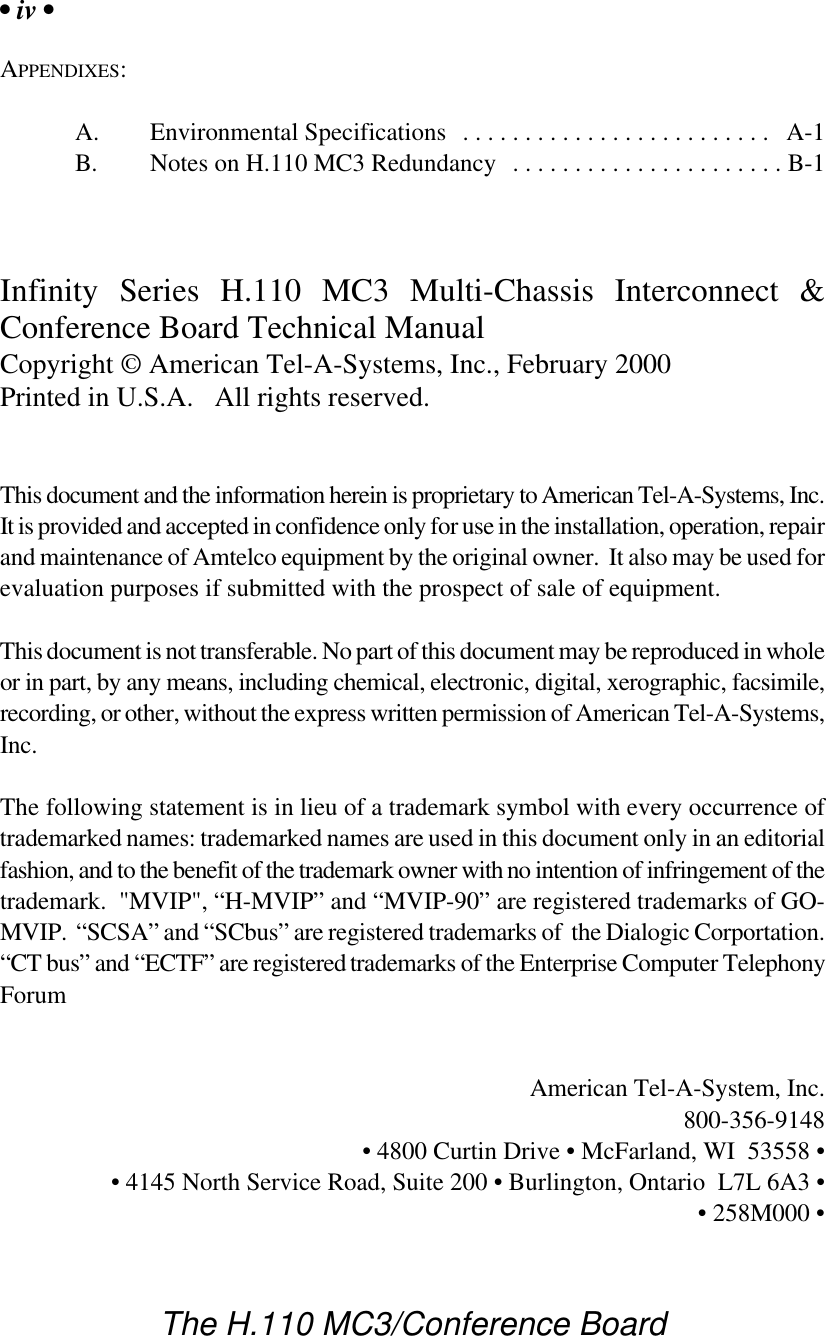
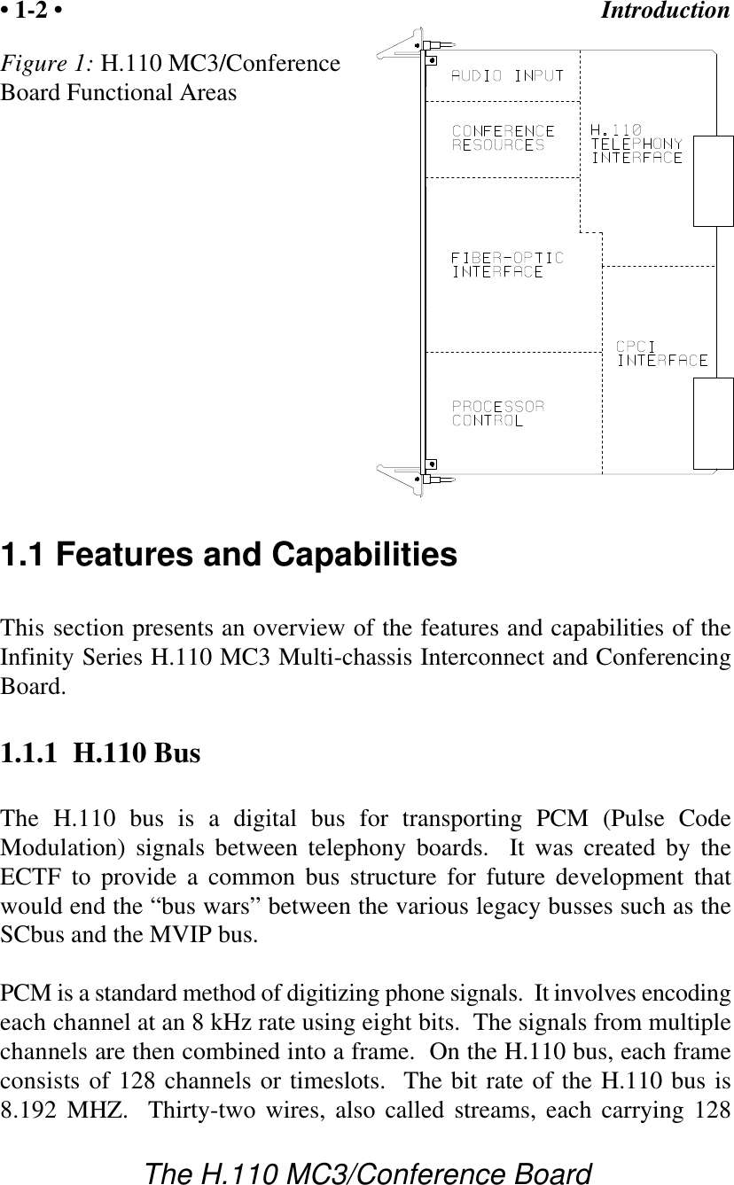
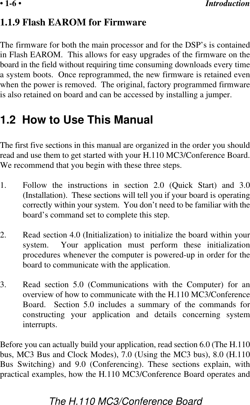
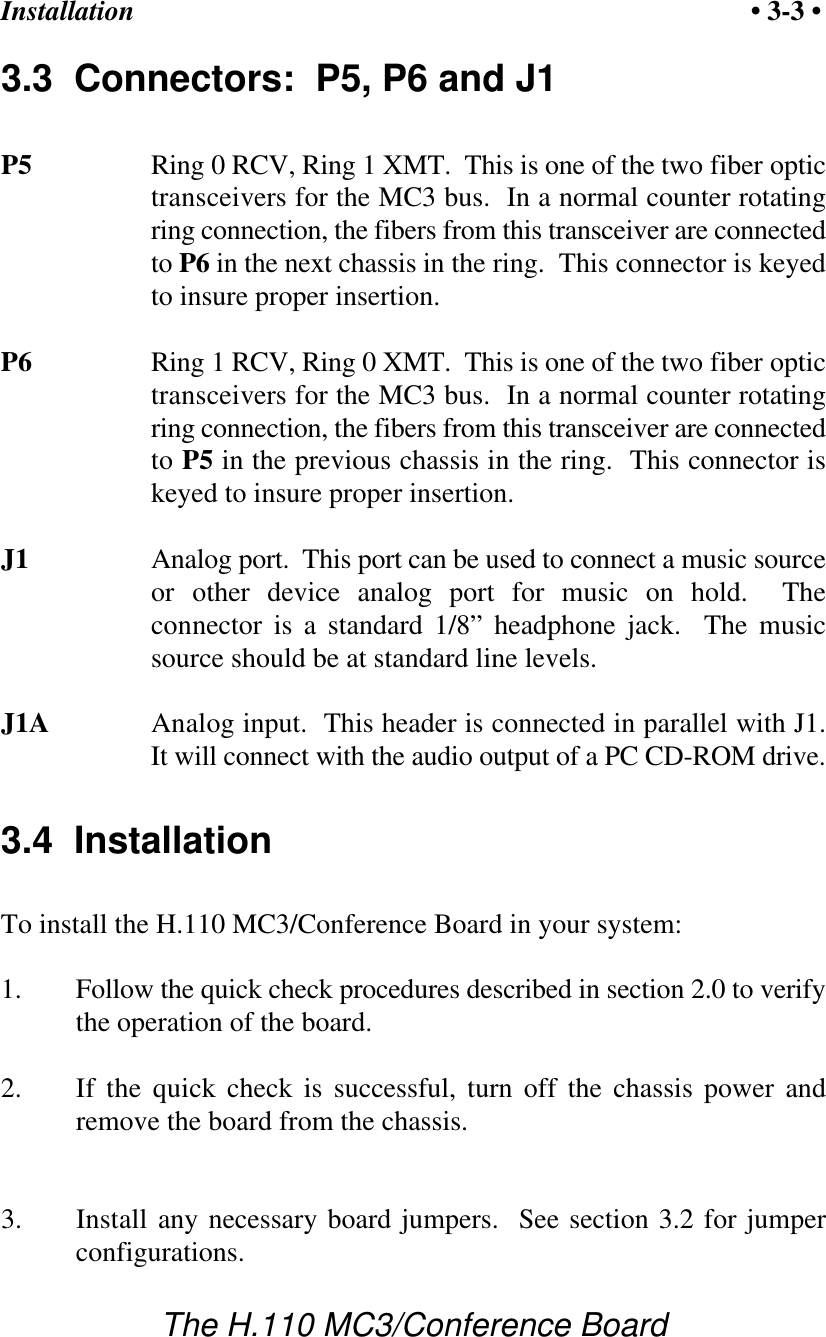
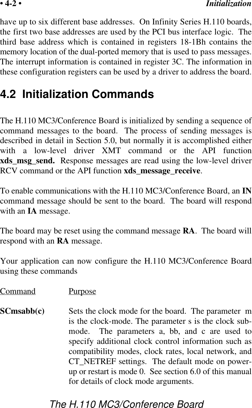
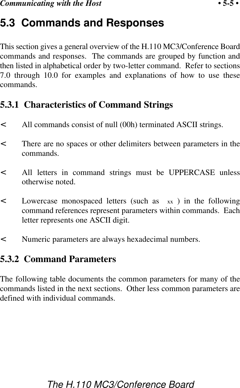
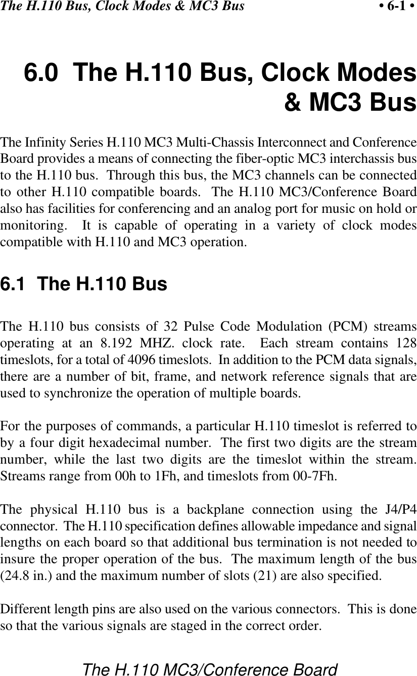
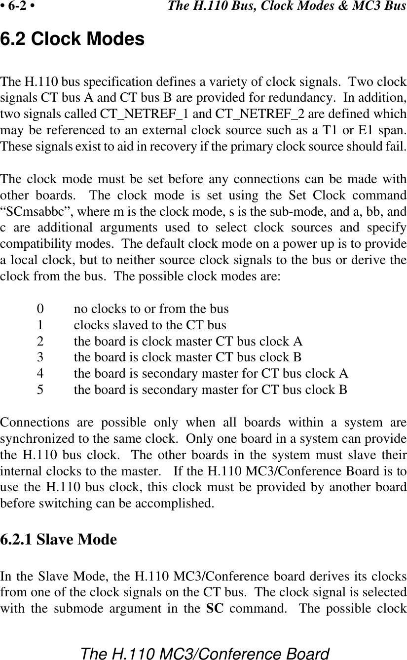
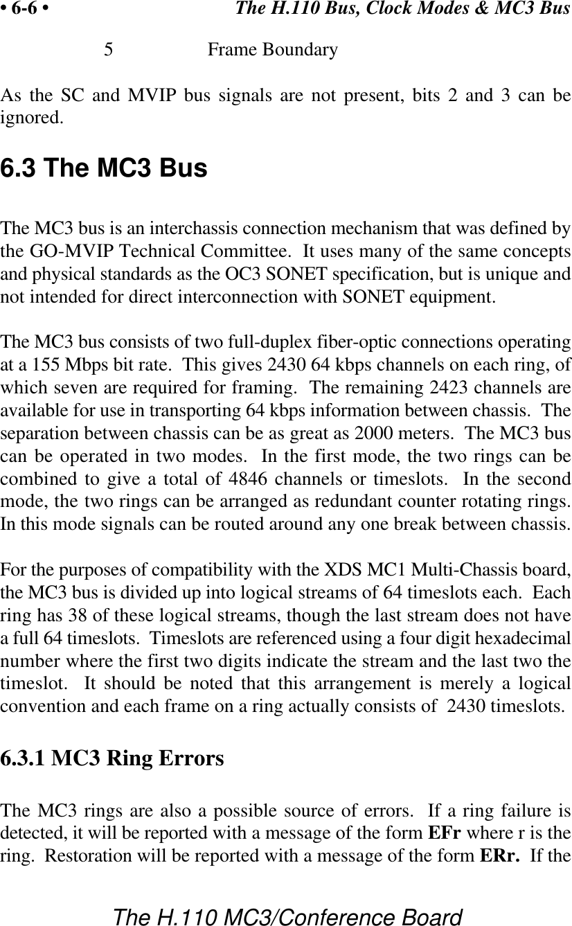
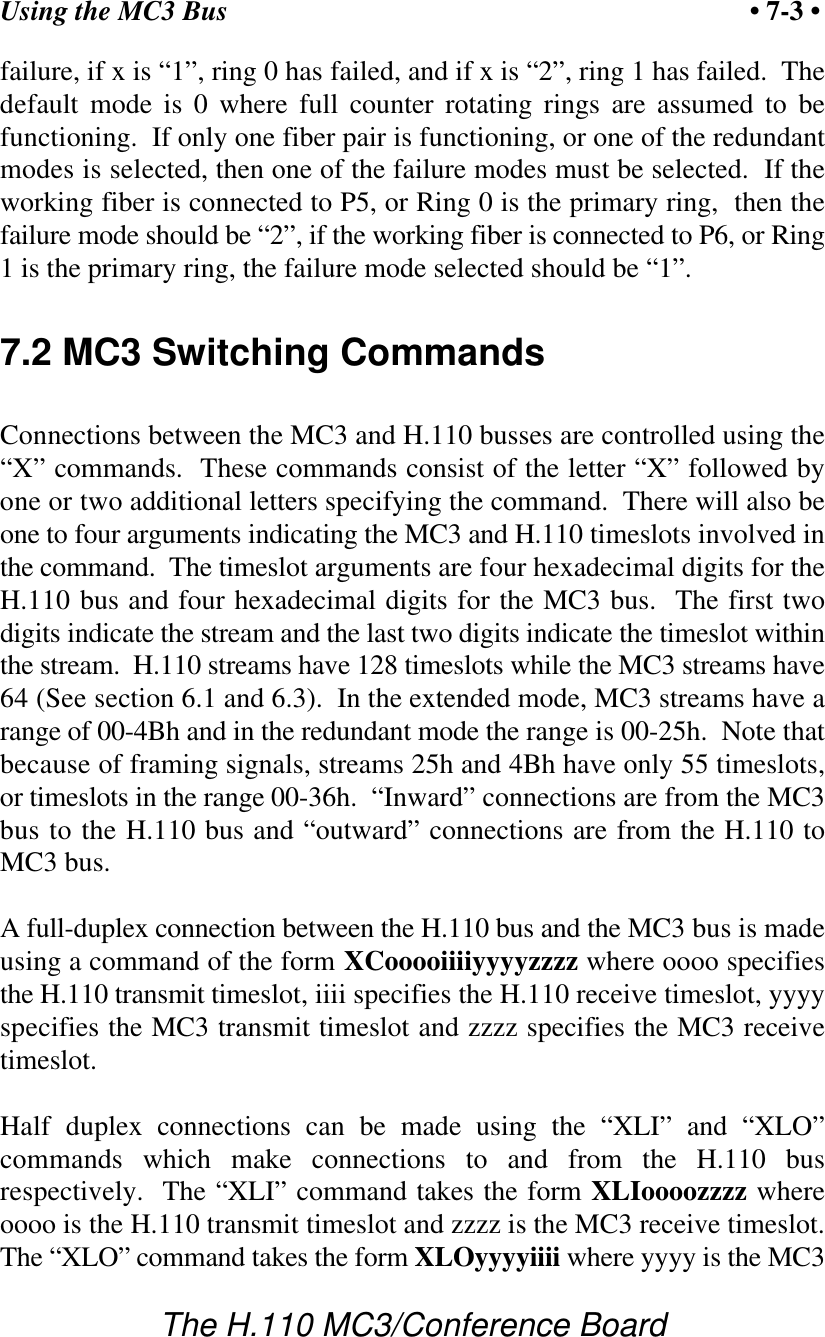
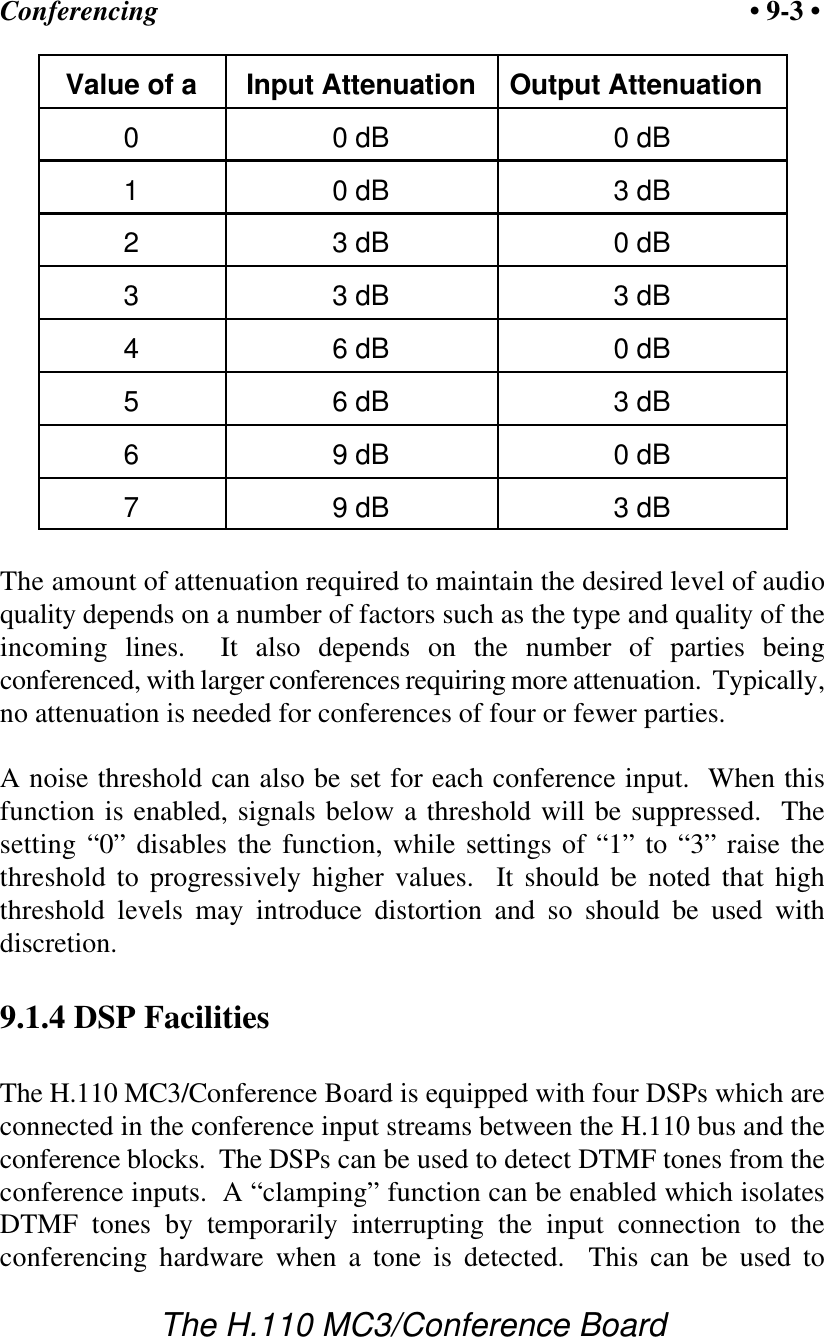
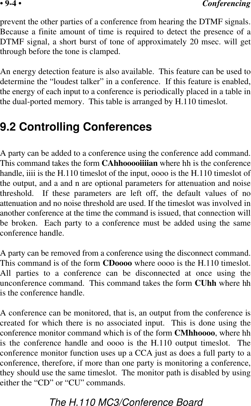
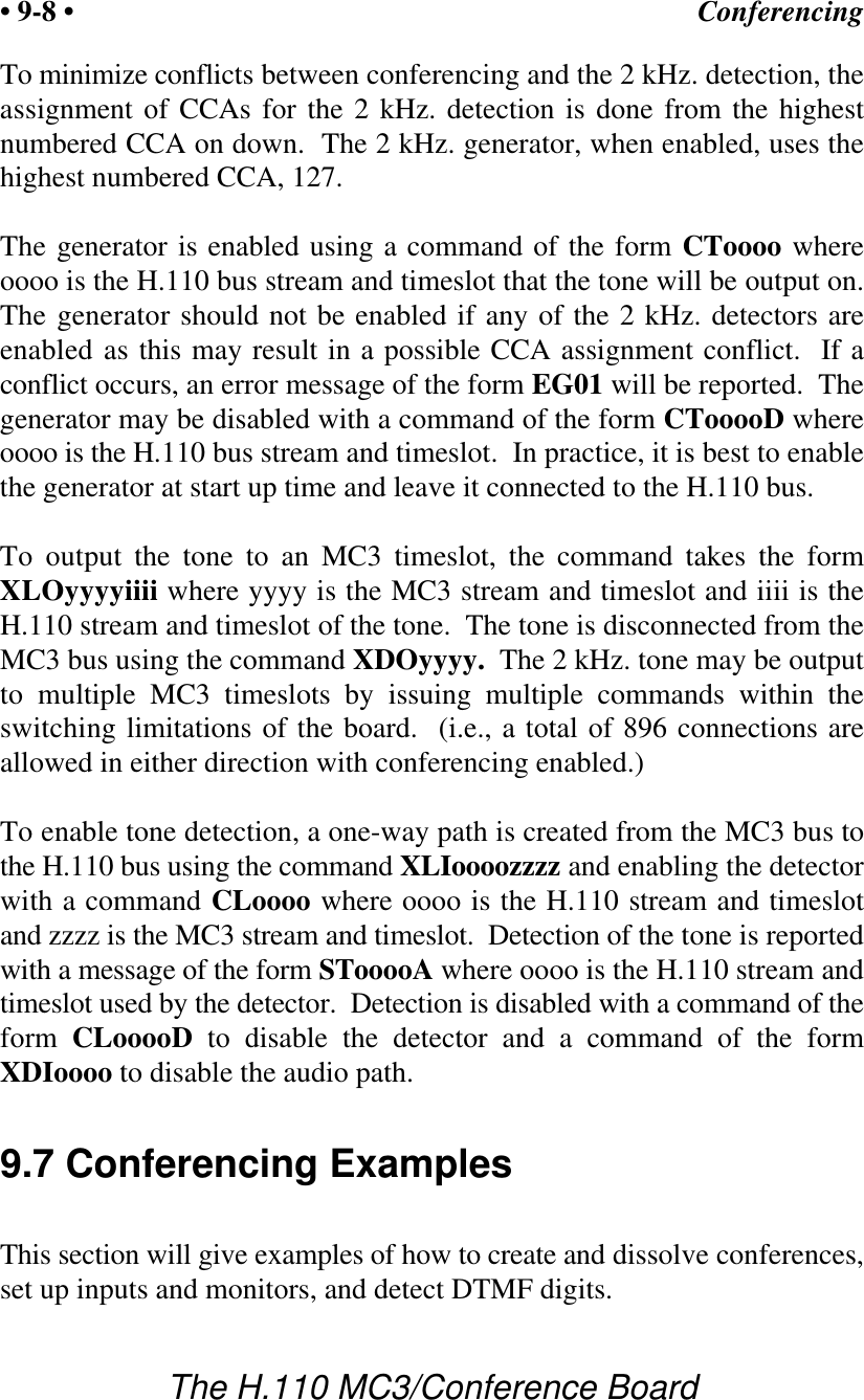
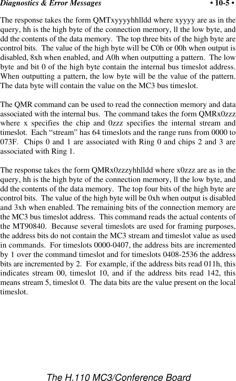
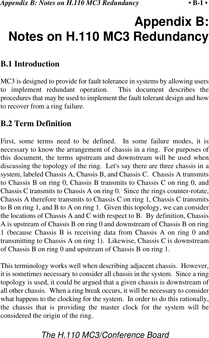
![Diagnostics & Error Messages• 10-4 •The H.110 MC3/Conference BoardESrxx A change in the ring status error bits has been detected forring r. The status bits are reported in xx. The bit values arebit description 0 LOS - loss of signal 1 LOF - loss of frame 2 OOF - out of frame 3 RFE - receive frame error 4 B1ERR - bit error 6 FSA - frame slip alarm 7 TXPPA - transmit phase alignment alarmU[cmnd] If the board does not recognize a command message, or if itdoes not have the appropriate number of arguments, the samemessage will be returned by the board preceded by a U toindicate an undefined message.10.3 QM QueriesThe QMT and QMR commands can be used to query the contents of theconnection and data memories of the chips used to interface to the MC3rings. Four MT90840 chips control the switching between the MC3 ringsand an internal bus, with two chips used for each ring. This internal bushas 1024 timeslots and is used to connect the MT90840 chips with theCT812 chips used to interface to the H.110 bus. These internal timeslotsare assigned dynamically with the first connection established using the firsttimeslot, the second connection the next timeslot and so on. When aconnection is disabled, the internal timeslot is released for use.The QMT command can be used to read the connection memory and dataassociated with the MC3 bus. The command takes the form QMTxyyyywhere x specifies the chip and yyyy specify the MC3 stream and timeslot.Each “stream” has 64 timeslots and the range runs from 0000 to 2536.The chips 0 and 1 are associated with Ring 0 and chips 2 and 3 areassociated with Ring 1.](https://usermanual.wiki/Amtelco/258A006.Users-Manual/User-Guide-121354-Page-76.png)