Amtelco 258A008 H.110 Basic Rate Interface ISDN User Manual
Amtelco (American Tel-A-Systems, Inc. H.110 Basic Rate Interface ISDN Users Manual
UserManual.wiki
>
Amtelco
>
258A008 User Manual
>
Users Manual
Contents
1.
Users Manual
2.
users manual
Users Manual
Navigation menu
Upload a User Manual
Namespaces
Wiki Guide
HTML
PDF
Info
Views
User Manual
Discussion / Help
Navigation

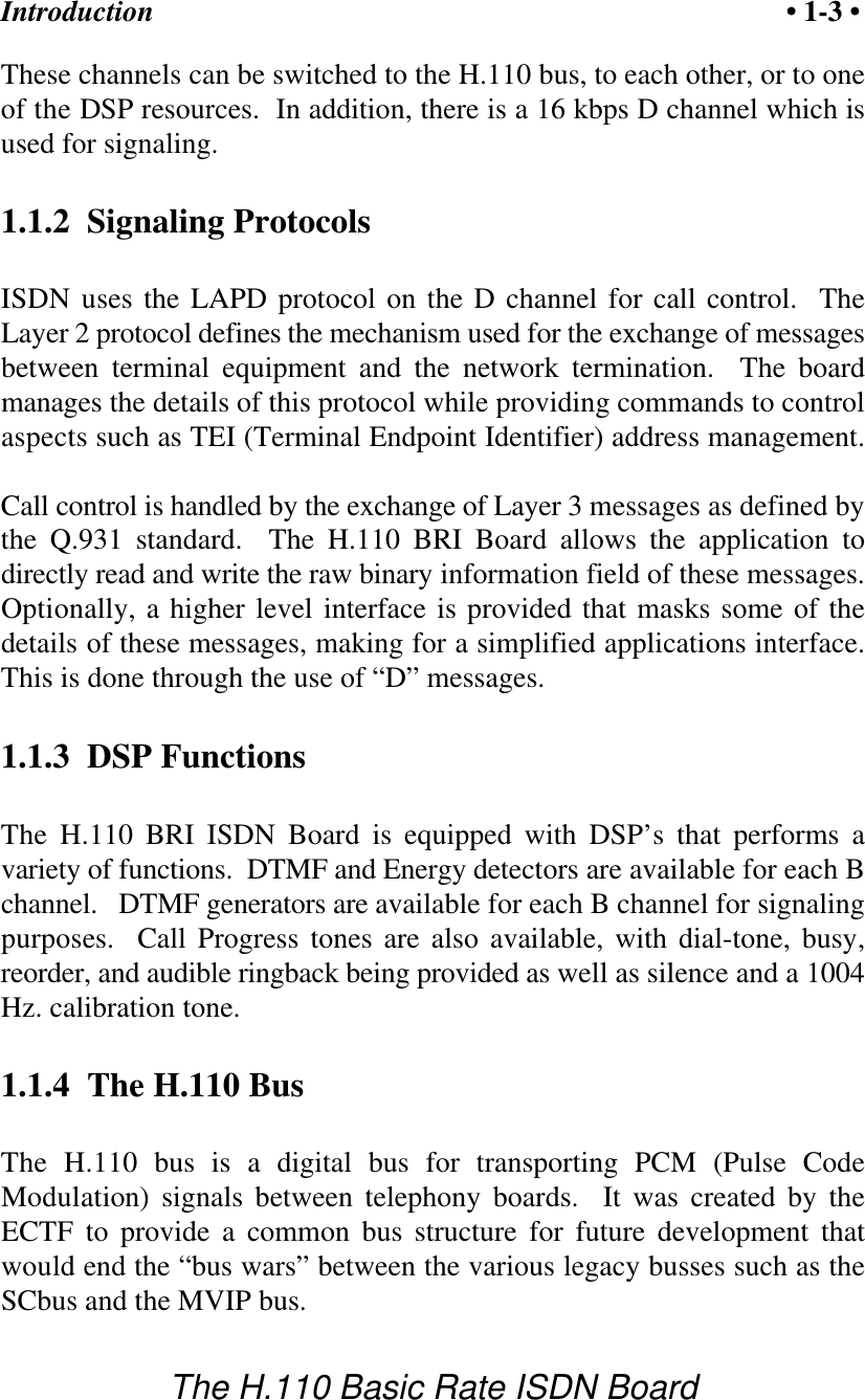
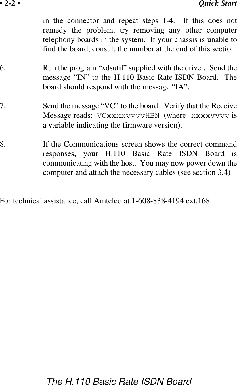
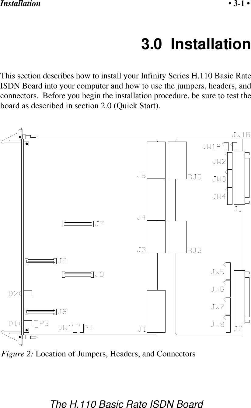

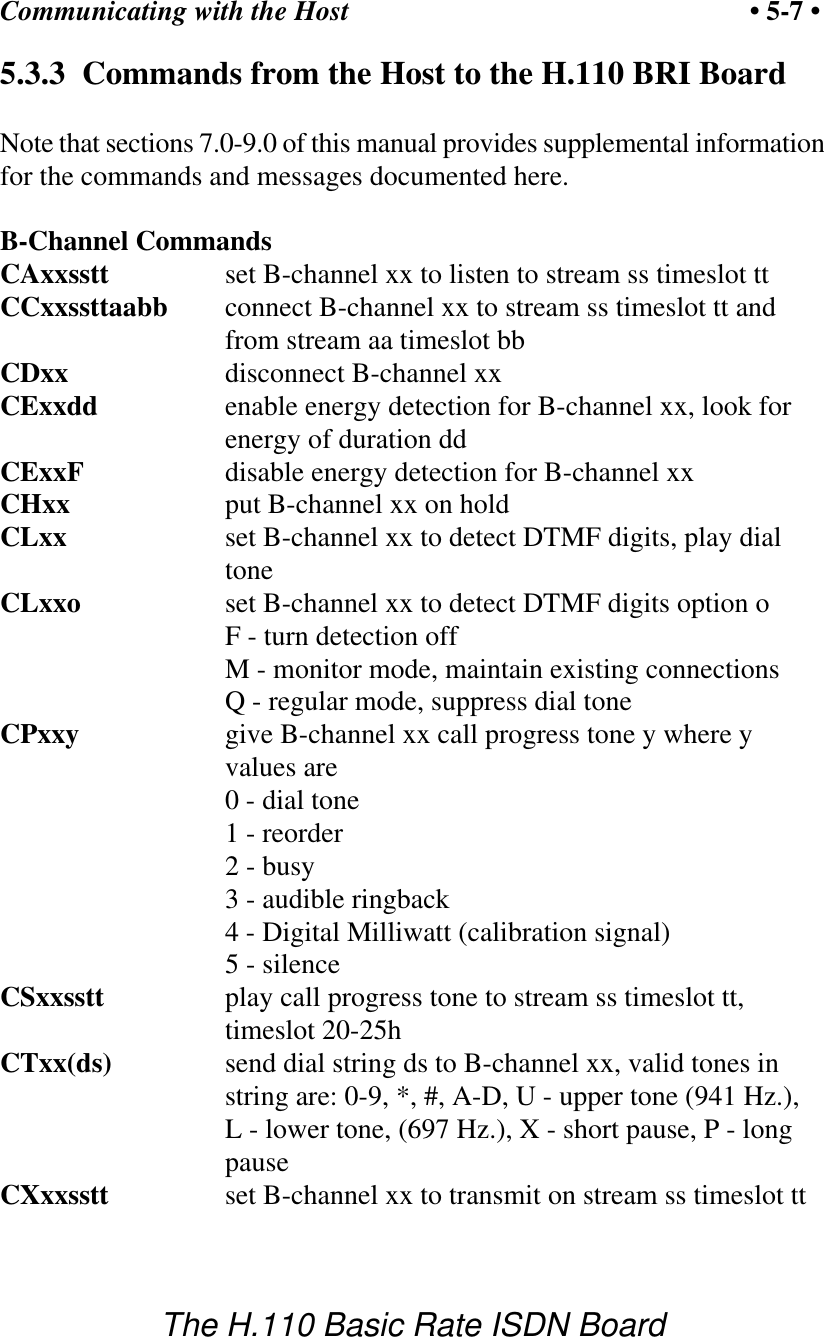

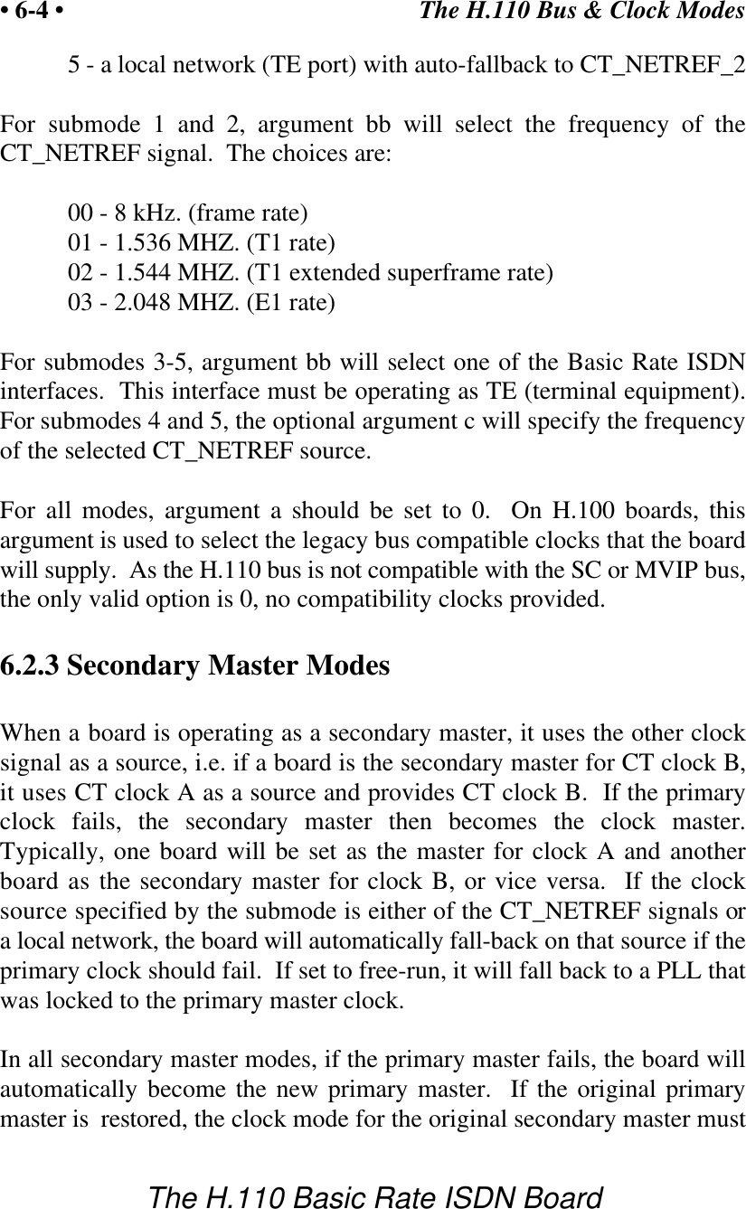

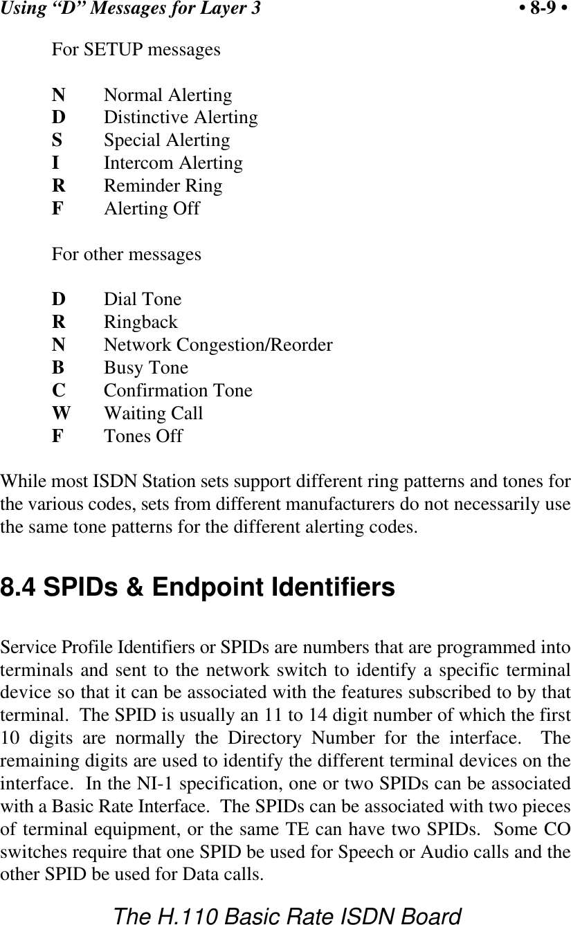
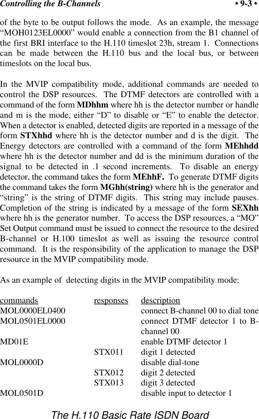
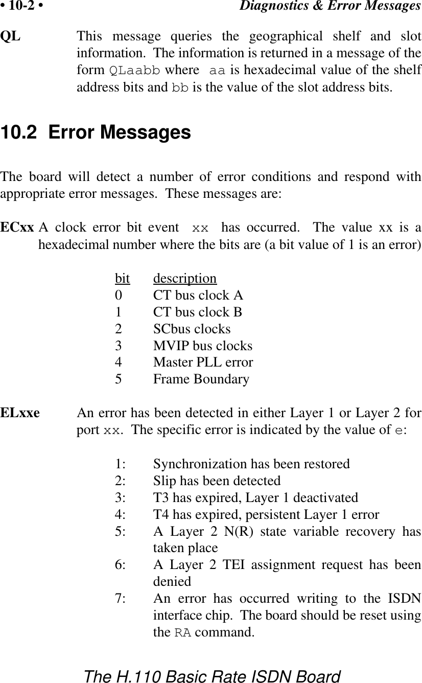
![Diagnostics & Error Messages • 10-3 •The H.110 Basic Rate ISDN Board8: Layer 1 anomaly has occurred, no actionneededEMxxe A Layer 2 protocol error has occurred on port xx. The erroris indicated by the value of e. This corresponds to theManagement Data Layer Indication in parentheses as definedby Q.921:1: MDL error (A) unsolicited supervisory response(F=1)2: MDL error (B) or (E) unsolicited DM response3: MDL error (C) or (D) unsolicited UA response4: MDL error (F) peer initiated reestablishment(SABME)5: MDL error (G) or (H) unsuccessfulretransmission of SABME or DISC6: MDL error (I) unsuccessful retransmission of astatus enquiry7: MDL error (J) N(R) state variable error8: MDL error (K) receipt of FRMR responseSM0 An EEPROM operation has failed. This indicates that eithera read or write to the EEPROM was unsuccessful.SM1 An EEPROM operation successfully completed.U[cmnd] If the board does not recognize a command message, or if itdoes not have the appropriate number of arguments, the samemessage will be returned by the board preceded by a U toindicate an undefined message.](https://usermanual.wiki/Amtelco/258A008.Users-Manual/User-Guide-121319-Page-107.png)