Amtelco 258A008 H.110 Basic Rate Interface ISDN User Manual
Amtelco (American Tel-A-Systems, Inc. H.110 Basic Rate Interface ISDN Users Manual
Amtelco >
Contents
- 1. Users Manual
- 2. users manual
Users Manual

Infinity Series H.110
Basic Rate ISDN Board
TECHNICAL MANUAL
Documentation Revision 0.3: June 7, 2000
Copyright © 2000
by American Tel-A-Systems, Inc.
All rights reserved.
258M001
This page left intentionally blank
• i •
The H.110 Basic Rate ISDN Board
Contents
1.0 INTRODUCTION ............................................. 1-1
1.1 Features and Capacities ............................... 1-1
1.1.1 The Physical Interface .......................... 1-2
1.1.2 Signaling Protocols ............................ 1-3
1.1.3 DSP Functions ................................ 1-3
1.1.4 The H.110 bus ................................ 1-3
1.1.5 Clock Modes ................................. 1-4
1.1.6 Hot Swap Capability ........................... 1-5
1.1.7 Message Passing .............................. 1-5
1.1.8 Flash EAROM for Firmware ..................... 1-5
1.1.9 EEPROM for Configuration Information ........... 1-5
1.1.10 Mezzanine Boards ............................. 1-6
1.2 How to Use This Manual .............................. 1-6
2.0 QUICK START .............................................. 2-1
3.0 INSTALLATION ............................................. 3-1
3.1 PCI Configuration ................................... 3-2
3.2 Jumpers & Headers for the Front Board .................. 3-2
3.3 Connectors: J7, J8, & J9 .............................. 3-2
3.4 Jumpers & Connectors for the Rear Board ................ 3-3
3.5 Installation ......................................... 3-4
3.6 Hot Swapping a Board ................................ 3-6
4.0 INITIALIZATION ............................................ 4-1
4.1 PCI Initialization .................................... 4-1
4.2 Initialization Commands .............................. 4-2
4.3 Configuration Memory ............................... 4-5
• ii •
The H.110 Basic Rate ISDN Board
5.0 COMMUNICATING WITH THE HOST .............................. 5-1
5.1 Commands and Responses Protocol ..................... 5-2
5.1.1 Sending Commands to the Board ................. 5-2
5.1.2 Reading Messages from the Board ................ 5-3
5.1.3 Reading Board Information ...................... 5-3
5.2 Interrupts .......................................... 5-4
5.2.1 Interrupt Initialization .......................... 5-4
5.2.2 Step-by-Step Summary ......................... 5-5
5.3 Commands and Responses ............................. 5-5
5.3.1 Characteristics of Command Strings ............... 5-5
5.3.2 Command Parameters .......................... 5-6
5.3.3 Commands from the Host to the H.110 BRI Board .... 5-7
< B-Channel Commands ........................ 5-7
< Layer 3 “D” Commands for NT Ports ............. 5-8
< Layer 3 “D” Commands for TE Ports ............ 5-10
< Interrupt Control Commands .................. 5-11
< Layer 3 Message Commands .................. 5-11
< MVIP Compatibility Commands ............... 5-11
< Query Commands ........................... 5-11
< Reset Commands ........................... 5-11
< Setup Commands ........................... 5-12
< TEI Management Commands .................. 5-12
< Version Requests ........................... 5-13
< Download Commands ........................ 5-13
< Diagnostics ................................ 5-13
5.3.4 Responses from the H.110 BRI ISDN Board ........ 5-14
< Acknowledgments ........................... 5-14
< Layer 3 “D” Responses for NT Ports ............ 5-14
< Layer 3 “D” Responses for TE Ports ............ 5-15
< Error Messages ............................. 5-17
< Layer 3 Messages Received Response ........... 5-18
< Query Responses ............................ 5-18
< B-Channel State Change Messages .............. 5-18
< TEI Management Responses ................... 5-18
< Diagnostic Responses ........................ 5-19
• iii •
The H.110 Basic Rate ISDN Board
6.0 THE H.110 BUS & CLOCK MODES .............................. 6-1
6.1 The H.110 Bus ...................................... 6-1
6.2 Clock Modes ....................................... 6-2
6.2.1 Slave Mode .................................. 6-3
6.2.2 Primary Master Mode .......................... 6-3
6.2.3 Secondary Master Mode ........................ 6-4
6.2.4 Clock Fallback ................................ 6-5
6.2.5 Clock Errors .................................. 6-5
6.3 Configuration Information ............................. 6-6
6.4 Hot Swap .......................................... 6-6
7.0 LAYER 1 & LAYER 2 PROTOCOLS ............................... 7-1
7.1 Layer 1 ............................................ 7-1
7.2 Layer 2 ............................................ 7-3
7.3 Layer 1 & Layer 2 States .............................. 7-5
7.4 TEI Management .................................... 7-6
7.5 The Packet Data Link ................................. 7-9
7.6 Sending and Receiving Layer 3 Messages ................ 7-10
8.0 USING “D” MESSAGES FOR LAYER 3............................. 8-1
8.1 Q.931 Messages ..................................... 8-1
8.2 “D” Command & Response Messages .................... 8-2
8.3 Information Elements ................................. 8-5
8.3.1 Bearer Capability .............................. 8-5
8.3.2 Cause ....................................... 8-5
8.3.3 Directory Numbers ............................. 8-7
8.3.4 Feature Keys & Indicator Status .................. 8-7
8.3.5 Progress Indicator ............................. 8-8
8.3.6 Signal ....................................... 8-8
8.4 SPIDs & Endpoint Identifiers .......................... 8-9
8.5 Directory Numbers .................................. 8-11
8.6 Display Text ....................................... 8-11
8.7 NT Call Handling Examples .......................... 8-12
8.7.1 A Call Terminating at a Terminal ................ 8-12
8.7.2 A Terminal Originating a Call ................... 8-13
• iv •
The H.110 Basic Rate ISDN Board
8.0 USING “D” MESSAGES FOR LAYER 3(CONTINUED):
8.8 TE Call Handling Examples .......................... 8-14
8.8.1 Originating a Call ............................ 8-14
8.8.2 A Terminating Call ........................... 8-15
8.9 HOLD & RETrieve ................................. 8-16
8.10 EKTS, CACH EKTS, and AT&T Custom ............... 8-17
8.11 Call Processing Errors ............................... 8-18
9.0 CONTROLLING THE B-CHANNELS ............................... 9-1
9.1 Overview of the Command Structure .................... 9-1
9.2 MVIP-95 Compatibility ............................... 9-2
9.3 Configuring the Board ................................ 9-4
9.4 Using the “C” Commands ............................. 9-5
9.4.1 Making a Connection ........................... 9-5
9.4.2 Call Progress Tones ............................ 9-6
9.4.3 Sending DTMF Tones .......................... 9-7
9.4.4 Detecting DTMF Tones ......................... 9-7
9.4.5 Detecting Energy .............................. 9-8
9.4.6 An Example of Originating a Call ................ 9-8
9.4.7 An Example of Receiving a Call .................. 9-9
9.4.8 An Example of Detecting DTMF ................. 9-10
10.0 DIAGNOSTICS & ERROR MESSAGES ............................ 10-1
10.1 Diagnostic Commands ............................... 10-1
10.2 Error Messages ..................................... 10-2
10.3 Diagnostic Tests .................................... 10-4
APPENDIXES:
A. Environmental Specifications ......................... A-1
• v •
The H.110 Basic Rate ISDN Board
Infinity Series H.110 Basic Rate ISDN Board Technical Manual
Copyright © American Tel-A-Systems, Inc., February 2000
Printed in U.S.A. All rights reserved.
This document and the information herein is proprietary to American Tel-A-Systems, Inc.
It is provided and accepted in confidence only for use in the installation, operation, repair
and maintenance of Amtelco equipment by the original owner. It also may be used for
evaluation purposes if submitted with the prospect of sale of equipment.
This document is not transferable. No part of this document may be reproduced in whole
or in part, by any means, including chemical, electronic, digital, xerographic, facsimile,
recording, or other, without the express written permission of American Tel-A-Systems,
Inc.
The following statement is in lieu of a trademark symbol with every occurrence of
trademarked names: trademarked names are used in this document only in an editorial
fashion, and to the benefit of the trademark owner with no intention of infringement of the
trademark. “MVIP”, “H-MVIP”, “MVIP-90”, and “MVIP-95” are registered trademarks
of GO-MVIP. "SCSA" and “SCbus” are registered trademarks of the Dialogic
Corporation. “CT bus” and “ECTF” are registered trademarks of the Enterprise
Computer Telephony Forum
American Tel-A-System, Inc.
800-356-9148
• 4800 Curtin Drive • McFarland, WI 53558 •
• 4145 North Service Road, Suite 200 • Burlington, Ontario L7L 6A3 •
• 258M001 •
• vi •
The H.110 Basic Rate ISDN Board
FCC Part 15 Requirements
WARNING: This equipment generates, uses, and can radiate radio frequency energy and
if not installed and used in accordance with the instruction manual, may cause interference
to radio communications. Operation of this equipment in a residential area is likely to cause
interference in which case the user at his own expense will be required to take whatever
measures may be required to correct the interference.
FCC Part 68 Registration
This equipment is registered with the FCC under Part 68 as a component device for use
with any generic PC Type computer or compatible. In order for FCC registration of this
product to be retained, all other products used in conjunction with this product to provide
your telephony function must also be FCC Part 68 registered for use with these hosts. If
any of these components are not registered, then you are required to seek FCC Part 68
registration of the assembled equipment prior to connection to the telephone network. Part
68 registration specifies that you are required to maintain the approval and as such become
responsible for the following:
-any component device added to your equipment, whether it bears component
registration or not, will require that a Part 68 compliance evaluation is done and
possibly that you have testing performed and make a modification filing to the FCC
before that new component can be used;
-any modification/update made by a manufacturer to any component device within
your equipment, will require that a Part 68 compliance evaluation is done and
possibly that you have testing performed and make a modification filing to the FCC
before the new component can be used;
-if you continue to assemble additional quantities of this compound equipment, you
are required to comply with the FCC’s Continuing Compliance requirements.
The telephone company has the right to request the registration information.
The Digital I/F FIC code for this equipment is 02IS5.
The Service Order code for this equipment is 6.oP.
The network Interface Jack for this equipment is an RJ49C.
The telephone company has the right to temporarily discontinue service. They are required
to provide notification and advise of the right to file a complaint.
• vii •
The H.110 Basic Rate ISDN Board
Changes to the BRI protocols offered by the telephone company may require changes to
the setup parameters of the board. The board may cease functioning until such changes
are made.
In case of trouble, you may be required to disconnect the board from the telephone lines
until the problem is resolved.
Connection to telephone company coin service is prohibited.
Connection to party lines is subject to state tariffs.
The authorized repair center is:
American Tel-A-System, Inc.
800-356-9148
4800 Curtin Drive
McFarland, WI 53558
There are no user serviceable components on the board. All repairs should be
accomplished by returning the board to Amtelco with a description of the problem.
• viii •
The H.110 Basic Rate ISDN Board
Canadian Customers
CP-01, Issue 8, Part 1
Section 14.1
Notice: “The industry Canada label identifies certified equipment. This
certification means that the equipment meets certain telecommunications network
protective, operational and safety requirements as prescribed in the appropriate
Terminal Equipment Technical Requirements document(s). The Department does
not guarantee the equipment will operate to the user’s satisfaction.
Before installing this equipment, users should ensure that it is permissible to be
connected to the facilities of the local telecommunications company. The
equipment must also be installed using an acceptable method of connection. The
customer should be aware that compliance with the above conditions may not
prevent degradation of service in some situations.
Repairs of certified equipment should be coordinated by a representative
designated by the supplier. Any repairs or alterations made by the user to this
equipment, or equipment malfunctions, may give the telecommunications company
cause to request the user to disconnect the equipment.
Users should ensure for their own protection that the electrical ground connections
of the power utility, telephone lines and internal metallic water pipe system, ir
present, are connected together. This precaution may be particularly important in
rural areas.
CAUTION: Users should not attempt to make such connections themselves, but
should contact the appropriate electric inspection authority, or electrician, as
appropriate.
• ix •
The H.110 Basic Rate ISDN Board
European Approvals
to be added after certification
• x •
The H.110 Basic Rate ISDN Board
Product Safety
The ISDN cord(s) must remain disconnected from the telecommunications
system until the card has been installed within a host which provides the
necessary protection of the operator.
If it is subsequently desired to open the host equipment for any reason, the
ISDN cord(s) must be disconnected prior to effecting access to any internal
parts which may carry telecommunications network voltages.
This board is not intended to be connected directly to the PSTN network.
Connection must be made by way of an approved NT-1 interface device.
It is the responsibility of the NT-1 to provide primary high voltage
protection.
Introduction • 1-1 •
The H.110 Basic Rate ISDN Board
1.0 Introduction
The Infinity Series H.110 Basic Rate Interface ISDN Board is designed to
provide thirty-two Basic Rate ISDN (Integrated Services Digital Network)
interfaces connected to the H.110 bus on a board with the CompactPCI
bus form factor. Each interface or port provides a D channel for call
control signaling and two 64 kbps. B channels for either speech or circuit
switched data. Each port can be independently configured as either a TE
(Terminal Equipment) or NT (Network Termination) interface. The board
provides complete support for the ISDN Layer 1 and Layer 2 protocols, as
well as optional support for the Layer 3 protocols as defined in Q.931. In
addition, the board is equipped with several DSP’s to provide tone
generation and detection.
The H.110 bus was devised by the Enterprise Computer Telephony Forum
(ECTF) to provide a single telecom bus for the entire industry. It is
intended for add-in boards using the CompactPCI form factor. A variety
of boards are available from a number of different vendors. The H.110
specifications also provides for hot swap capabilities for use in high
availability applications.
The board is equipped with a processor that can be used to control the
lower level functions of the board. The host PC controls the board using
messages passed through dual-ported RAM. The board shares a common
message passing and control scheme with other Infinity Series H.110
boards.
1.1 Features and Capabilities
This section presents an overview of the features and capabilities of the
Infinity Series H.110 Basic Rate Interface ISDN Board.
Introduction• 1-2 •
The H.110 Basic Rate ISDN Board
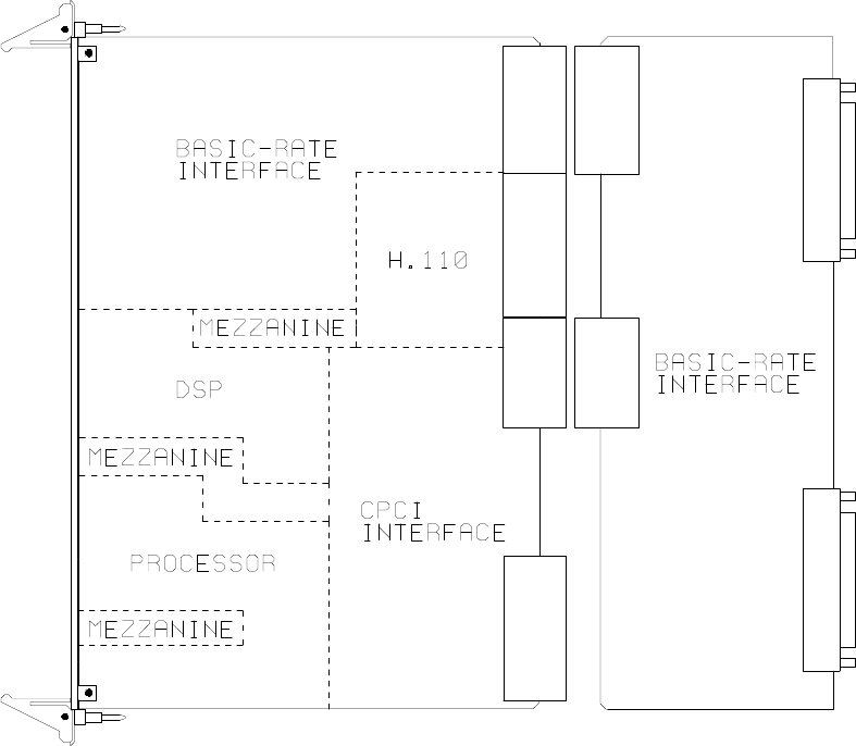
Figure 1: The H.110 Basic Rate ISDN Board Functional Areas
1.1.1 The Physical Interface
Thirty-two independent ports are provided on the board. Each port on the
board provides a complete S/T Basic Rate ISDN interface. This interface
can be configured under software control as either a piece of terminal
equipment to interface to a central office or PBX, or as a network
termination to interface to terminal equipment such as ISDN phone sets or
ISDN modems. Layer 1 support is provided by the board to handle all the
details of framing and clocking.
Each port provides two independent B1 channels which operate at 64 kbps.
Introduction • 1-3 •
The H.110 Basic Rate ISDN Board
These channels can be switched to the H.110 bus, to each other, or to one
of the DSP resources. In addition, there is a 16 kbps D channel which is
used for signaling.
1.1.2 Signaling Protocols
ISDN uses the LAPD protocol on the D channel for call control. The
Layer 2 protocol defines the mechanism used for the exchange of messages
between terminal equipment and the network termination. The board
manages the details of this protocol while providing commands to control
aspects such as TEI (Terminal Endpoint Identifier) address management.
Call control is handled by the exchange of Layer 3 messages as defined by
the Q.931 standard. The H.110 BRI Board allows the application to
directly read and write the raw binary information field of these messages.
Optionally, a higher level interface is provided that masks some of the
details of these messages, making for a simplified applications interface.
This is done through the use of “D” messages.
1.1.3 DSP Functions
The H.110 BRI ISDN Board is equipped with DSP’s that performs a
variety of functions. DTMF and Energy detectors are available for each B
channel. DTMF generators are available for each B channel for signaling
purposes. Call Progress tones are also available, with dial-tone, busy,
reorder, and audible ringback being provided as well as silence and a 1004
Hz. calibration tone.
1.1.4 The H.110 Bus
The H.110 bus is a digital bus for transporting PCM (Pulse Code
Modulation) signals between telephony boards. It was created by the
ECTF to provide a common bus structure for future development that
would end the “bus wars” between the various legacy busses such as the
SCbus and the MVIP bus.
Introduction• 1-4 •
The H.110 Basic Rate ISDN Board
PCM is a standard method of digitizing phone signals. It involves encoding
each channel at an 8 kHz rate using eight bits. The signals from multiple
channels are then combined into a frame. On the H.110 bus, each frame
consists of 128 channels or timeslots. The bit rate of the H.110 bus is
8.192 MHZ. Thirty-two wires, also called streams, each carrying 128
timeslots, are combined to form the bus, and provide a total of 4096
timeslots. Two timeslots are required for a full conversation, one for each
talker.
In addition to the streams, a number of other signals necessary to maintain
synchronization between all the boards in the system are carried on the bus.
These signals provide the clocking and framing information. Redundant
clocks are provided to aid in recovery if the primary clock should fail.
The H.110 bus consists of backplane connections on a 6U CompactPCI
backplane that is used to interconnect the boards in the system. The CT
Bus connections are made through the J4/P4 connector. The electrical and
mechanical requirements of H.110 boards are tightly specified to insure the
reliability and consistent performance of the CT Bus in any valid
configuration of conforming boards.
1.1.5 Clock Modes
The H.110 BRI Board can operate in a variety of clock modes. Modes are
available so that the master clock can either be derived from the H.110 bus,
one of the Basic Rate Interfaces, or be provided by the H.110 BRI Board.
The clock redundancy and clock fallback functions of the H.110 bus are
also supported so that the H.110 BRI Board can be set to provide a clock
to the H.110 bus if the master clock on that bus should fail.
1.1.6 Hot Swap Capability
The H.110 Specification includes “hot swap” capability. This capability
allows for the insertion and removal of boards from a live system. Not
only are there provisions for controlling the electrical signals to prevent
disruption when inserting and removing boards, but also for informing
Introduction • 1-5 •
The H.110 Basic Rate ISDN Board
drivers and applications so that the board resources can be managed as they
are added or deleted. Each H.110 board is provided with a blue LED that
is used to inform an operator when it is safe to insert or remove a board.
1.1.7 Message Passing
The board occupies 8K of memory space on the host PC. This 8K may
reside anywhere within the PC’s address space. As a CompactPCI board,
the address and interrupt of the board is assigned at boot time. The
message passing scheme used by the Infinity Series H.110 BRI Board is
identical to that of the other Infinity Series H.110 boards, allowing for the
easy combination of a variety of Infinity Series H.110 boards in a single
system.
The message passing scheme and message syntax of Infinity Series H.110
boards is similar to that of the older Infinity Series H.100 boards and XDS
series of MVIP and SCbus boards. This facilitates the easy migration from
ISA and PCI systems to designs using CompactPCI boards
1.1.8 Flash EAROM for Firmware
The firmware for both the main processors and for the DSP’s is contained
in Flash EAROM. This allows for easy upgrades of the firmware on the
board in the field without requiring time consuming downloads every time
a system boots. Once reprogrammed, the new firmware is retained even
when the power is removed. The original, factory programmed firmware
is also retained on board and can be accessed by installing a jumper.
1.1.9 EEPROM for Configuration Information
ISDN interfaces can require a substantial amount of information to be
programmed into the system. These includes items such as the SPIDs
(Service Profile Identifiers) and DNs (Directory Numbers) associated with
each interface as well as board configuration information such as the type
of port (NT or TE) and the protocol level supported. To reduce the burden
Introduction• 1-6 •
The H.110 Basic Rate ISDN Board
on the application, the board has an EEPROM capable of providing non-
volatile storage for this information. This allows the board to automatically
configure itself upon a restart.
1.1.10 Mezzanine Boards
The H.100 BRI Board provides connectors for attaching two mezzanine
boards. These mezzanine boards can be used for additional processing of
signals on the B-channels. The connectors are compatible with the Bicom
Flex Port DSP Card which can be used for speech processing or providing
fax services. Future mezzanine boards may be provided to allow for digital
data services using the B-channels.
1.2 How to Use This Manual
The first five sections in this manual are organized in the order you should
read and use them to get started with your H.110 BRI ISDN Board. We
recommend that you begin with these three steps.
1. Follow the instructions in section 2.0 (Quick Start) and 3.0
(Installation). These sections will tell you if your board is operating
correctly within your system. You don’t need to be familiar with the
board’s command set to complete this step.
2. Read section 4.0 (Initialization) to initialize the board within your
system. Your application must perform these initialization
procedures whenever the computer is powered up in order for the
board to communicate with application.
3. Read section 5.0 (Communications with the Computer) for an
overview of how to communicate with the H.110 BRI ISDN Board.
Section 5.0 includes a summary of the commands for constructing
your application and details concerning system interrupts.
Introduction • 1-7 •
The H.110 Basic Rate ISDN Board
Before you can actually build your application, read section 6.0 (The H.110
Bus and Clock Modes), 7.0 (Layer 1 and Layer 2 Protocols), 8.0 (Using
“D” Messages for Layer 3) and 9.0 (Controlling the B-Channels). These
sections explain, with practical examples, how the H.110 BRI ISDN Board
operates and how to use the command set to achieve the desired results.
Section 10.0 explains diagnostic and error messages that may occur.
The Appendix contains information on power requirements and interfacing
that will be helpful installing your H.110 BRI ISDN Board.
Introduction• 1-8 •
The H.110 Basic Rate ISDN Board
this page intentionally left blank
Quick Start • 2-1 •
The H.110 Basic Rate ISDN Board
2.0 Quick Start
This section describes the first steps you should perform to determine if
your Infinity Series H.110 Basic Rate ISDN Board is communicating
correctly with your CompactPCI system. You can perform this quick check
without connecting any cables.
The exact procedure will vary depending on which operating system you
are running. For each operating systems, drivers are required to interface
to the boards. The drivers supplied by Amtelco have tests built into them
to verify communications with the boards. These drivers also come
supplied with utility programs that allow the developer to test
communications with the board. Please consult the appropriate
documentation for the driver and operating system you are using.
Quick Start Procedure
1. With the chassis power off, insert the board into a slot.
2. Turn on the computer.
3. If the Amtelco driver is not already installed, install it now,
following the instructions supplied with the driver.
4. Most Amtelco drivers will display a list of boards that are
installed (see the documentation for the particular driver that
you are using). If the H.110 Basic Rate ISDN Board is listed,
skip to step 6.
5. If the board is not listed, there may be a problem with the
board not being seated correctly in the backplane. There may
also be a problem with a memory or interrupt conflict. Power
down the chassis and check that the board is properly seated
Quick Start• 2-2 •
The H.110 Basic Rate ISDN Board
in the connector and repeat steps 1-4. If this does not
remedy the problem, try removing any other computer
telephony boards in the system. If your chassis is unable to
find the board, consult the number at the end of this section.
6. Run the program “xdsutil” supplied with the driver. Send the
message “IN” to the H.110 Basic Rate ISDN Board. The
board should respond with the message “IA”.
7. Send the message “VC” to the board. Verify that the Receive
Message reads: VCxxxxvvvvHBN (where xxxxvvvv is
a variable indicating the firmware version).
8. If the Communications screen shows the correct command
responses, your H.110 Basic Rate ISDN Board is
communicating with the host. You may now power down the
computer and attach the necessary cables (see section 3.4)
For technical assistance, call Amtelco at 1-608-838-4194 ext.168.
Installation • 3-1 •
The H.110 Basic Rate ISDN Board
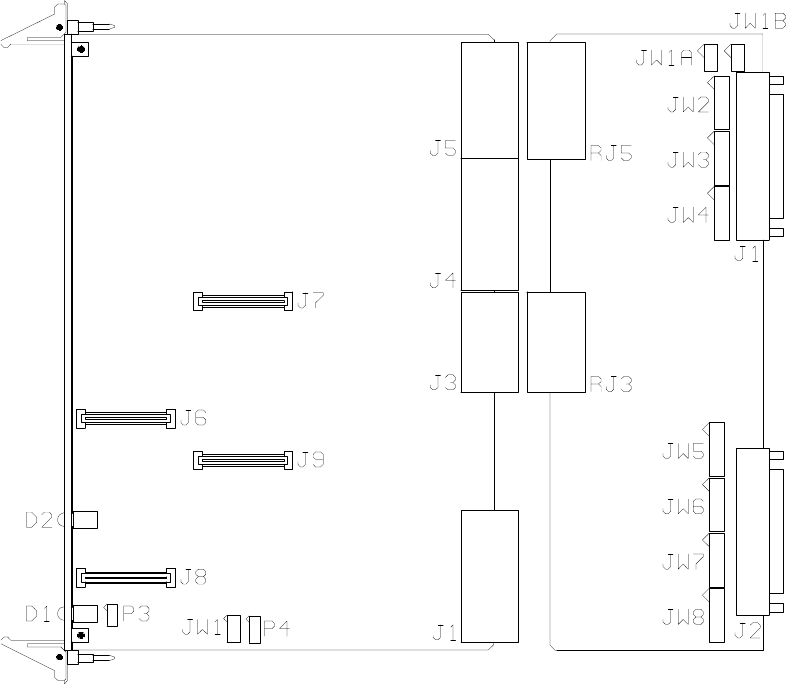
Figure 2: Location of Jumpers, Headers, and Connectors
3.0 Installation
This section describes how to install your Infinity Series H.110 Basic Rate
ISDN Board into your computer and how to use the jumpers, headers, and
connectors. Before you begin the installation procedure, be sure to test the
board as described in section 2.0 (Quick Start).
Installation• 3-2 •
The H.110 Basic Rate ISDN Board
The Infinity Series H.110 Basic Rate ISDN Board actually consists of two
boards. The front board which contains the processor, DSP’s, switching,
HDLC controllers, and logic. The rear board contains the interface and
connectors to the Basic Rate Interface ports.
3.1 PCI Configuration
As Infinity Series boards conform to the PCI standards, there are no
switches to set to configure the H.110 BRI Board's memory address, I/O
addresses, or interrupt. The host processor’s bios will automatically
configure the board at boot time to avoid conflicts with other boards in the
system.
3.2 Jumpers & Headers for the Front Board
The following is a complete list of all jumpers for the H.110 BRI ISDN
Board:
JW1-1 Firmware Select. If firmware has been downloaded to the
board, this jumper selects whether the downloaded firmware
or the factory default firmware is used. When this jumper is
installed, the factory default firmware is executed whenever
the board is reset. When the jumper is not installed, the
downloaded firmware will be executed after a reset if it is
present. If no downloaded firmware is present, the factory
default firmware is executed after reset.
JW1-2 DSP Firmware Select. Two separate firmware programs are
included in the EAROM, one for the board processor and
one for the DSP. If JW1-2 is installed and downloaded DSP
firmware is present, the factory DSP firmware is executed
after reset. Otherwise, the downloaded firmware is executed
if present. See JW1-1.
Installation • 3-3 •
The H.110 Basic Rate ISDN Board
JW1-3 Undefined, reserved for future use.
JW1-4 Undefined, reserved for future use.
P3 Diagnostic port. Never install jumpers here.
P4 This header is used for programming internal logic and should
never be jumpered.
3.3 Connectors: J7, J8, & J9
J7 This connector is used for the installation of a mezzanine
board.
J8 This connector is used for the installation of a mezzanine
board.
J9 This connector is used for the installation of a mezzanine
board.
3.4 Jumpers & Connectors for the Rear Board
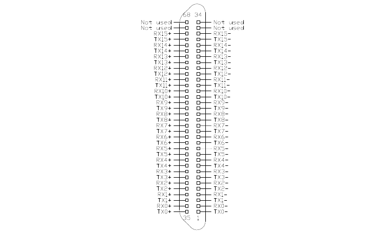
J1 Basic Rate ISDN Connections for port 0-15. This connector
is a 68 pin SCSI-3 type connector. It contains two pairs for
each Basic Rate ISDN port or interface on the board. See
Figure 3.
J2 Basic Rate ISDN Connections for ports 16-31. This
connector is a 68 pin SCSI-3 type connector. It contains two
pairs for each Basic Rate ISDN port or interface on the
board. See Figure 3.
JW1-8 These jumpers terminate the individual BRI ports.
Termination is required if the port is to be used as an NT
(network termination) or if it the last or only TE (terminal
Installation• 3-4 •
The H.110 Basic Rate ISDN Board
Figure 3: J1 & J2 Pin Assignments
equipment) on the interface. The jumpers should be installed
when termination is required. Each port requires two jumpers
with port 0 using the first pair of jumpers on JW1, and port
31 using the last pair of jumpers on JW8.
3.4 Installation
To install the H.110 BRI ISDN Board in your system:
1. Do not connect the board to the PSTN. Follow the quick check
procedures described in section 2.0.
2. If the quick check is successful, turn off the chassis power and
remove the board from the chassis.
3. Install any necessary board jumpers. See section 3.2 for jumper
configurations.
Installation • 3-5 •
The H.110 Basic Rate ISDN Board
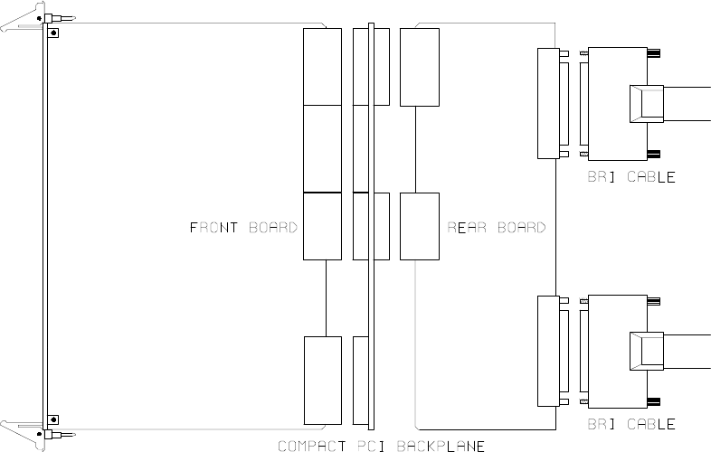
Figure 4: Installing Cables on J1 and J2
4. Reinsert the front board into the chassis. Seat it properly in a slot in
the chassis and secure it with the front panel handles. Do not
connect the board to the PSTN.
5. Insert the rear board into the corresponding slot on the rear panel.
6. Connect the host chassis to the mains supply using a socket-outlet
with protective earthing connection and connect any additional
protective earthing used.
7. Connect the telephone cables to J1 & J2. The telephone cable
terminates in a 68 pin SCSI-3 male connector. Secure with
mounting screws.
If it is subsequently desired to open the host equipment chassis for any
reason, the PSTN cable must be detached prior to effecting access to any
internal parts which may carry telecommunications network voltages.
Installation• 3-6 •
The H.110 Basic Rate ISDN Board
3.5 Hot Swapping a Board
The Infinity Series H.110 Basic Rate ISDN Board can be “hot swapped,”
that is it can be removed from a functioning system without turning the
power off or interrupting applications. However, to be able to do this, the
host processor must be equipped with suitable hot swap drivers as well as
a hot swap manager which will alert applications when a board has been
inserted or removed from the system so that resources can be properly
managed. It is beyond the scope of this manual to describe the operation
of either the hot swap driver or hot swap manager.
Each H.110 board is equipped with a switch linked to the lower ejector tab
and a blue LED. This combination is used to coordinate the actions of an
operator with the system software. When inserting a board, the board is
pushed in part of the way until the blue LED is illuminated. The insertion
may then be completed. When the connection process is complete, the
LED will go out. To remove a board, the lower ejector handle is depressed
until it is in the unlatched position. When the blue LED comes on, the
board may be removed from the system.
The rear board MUST ALWAYS be inserted BEFORE the front board,
and removed AFTER the front board.
To install the front board in a system under power:
1. Insert the board with the ejector tabs spread apart until partially
engaged.
2. Wait until the blue LED is illuminated.
3. Finish inserting the board by pushing the ejector tabs towards each
other. The LED should then go out.
Installation • 3-7 •
The H.110 Basic Rate ISDN Board
To remove the front board from a system under power:
1. Depress the lower ejector tab until it is in the unlatched position.
2. Wait until the blue LED is illuminated.
3. Finish removing the board by spreading the ejector tabs apart until
the board is ejected.
To insert the rear panel board into a system under power:
1. The rear board should be disconnected from the PSTN. Make sure
there is no board in the corresponding front panel slot.
2. Insert the rear board.
3. Connect the telephone cables to J1 & J2. The telephone cable
terminates in a 68 pin SCSI-3 male connector. Secure with
mounting screws.
4. Insert the front board as described above.
To remove a rear panel board from a system under power:
1. Remove the front board as described above.
2. Disconnect the PSTN cables from J1 and J2.
3. Remove the rear board from the system.

Installation• 3-8 •
The H.110 Basic Rate ISDN Board
Figure 6: Front Panel with Aux
and Hot Swap LED and top and
bottom ejector handles
Initialization • 4-1 •
The H.110 Basic Rate ISDN Board
4.0 Initialization
This section describes the procedures necessary to initialize the system and
enable the host computer to communicate with the Infinity Series H.110
Basic Rate ISDN Board. XDS drivers will implement some of these
procedures.
4.1 PCI Initialization
The system BIOS is responsible for recognizing CompactPCI boards and
mapping them into the I/O and memory spaces as required. It is also
responsible for assigning interrupts to the board. This is done through a set
of on board registers which contain information specifying the memory,
I/O, and interrupt needs of the board. A set of BIOS functions exist for
accessing this information. A detailed description of these functions can be
found in the PCI BIOS Specification published by the PCI SIG, the PCI
Special Interest Group.
Normally, the drivers supplied by Amtelco will take care of the process of
finding Infinity Series boards and establishing communications. The
information in the rest of this subsection is for background only.
The configuration registers of every CompactPCI board contain a vendor
ID and device ID code. These codes are unique to each board vendor. All
Infinity Series H.110 boards have the same vendor and device IDs. The
vendor ID is 14E3h and the device ID is 0101h. A BIOS function exists
that will find each instance of a particular vendor and device ID, and which
returns with a bus and device number. The bus and device number is then
used in functions to read the configuration registers.
The configuration registers contain information on the base address of the
memory and I/O assigned to the board by the BIOS. A PCI board may

Initialization• 4-2 •
The H.110 Basic Rate ISDN Board
have up to six different base addresses. On Infinity Series H.110 boards,
the first two base addresses are used by the PCI bus interface logic. The
third base address which is contained in registers 18-1Bh contains the
memory location of the dual-ported memory that is used to pass messages.
The interrupt information is contained in register 3Ch. The information in
these configuration registers can be used by a driver to address the board.
4.2 Initialization Commands
The H.110 BRI ISDN Board is initialized by sending a sequence of
command messages to the board. The process of sending messages is
described in detail in Section 5.0, but normally it is accomplished either
with a low-level driver XMT command or the API function
xds_msg_send. Response messages are read using the low-level driver
RCV command or the API function xds_message_receive.
To enable communications with the H.110 BRI ISDN Board, an IN
command message should be sent to the board. The board will respond
with an IA message.
The board may be reset using the command message RA. The board will
respond with an RA message.
Your application can now configure the H.110 BRI Board using these
commands
Command Purpose
SCmsabb(c) Sets the clock mode for the board. The parameter m
is the clock-mode. The parameter s is the clock sub-
mode. The parameters a, bb, and c are used to
specify additional clock control information such as
clock rates, local network, and CT_NETREF settings.
The default mode on power-up or restart is mode 0.
See section 6.0 of this manual for details of clock
mode arguments.
Initialization • 4-3 •
The H.110 Basic Rate ISDN Board
SEx Sets the encoding mode for the board. The parameter
x can be either M for Mu-Law as used in North
America and Japan, or A for A-Law as used in Europe
and Asia. The default value is for Mu-Law.
SFb(xx...xx) Sets the power feed enable for each port in a bank of
sixteen on the board. The H.110 BRI ISDN Board
can supply PS1 power for terminal devices connected
to ports configured as an NT. The bank b can be
either “L” for the ports 0-15 or “H” for ports 16-31.
The parameter can be “F” to turn the power feed off,
“N” to turn it on, or “*” for no change. The port type
parameter must be included of each of the 16 ports in
the bank.
SSxy Set Layer 2 system options. x and y can take values
of 0 or 1. If x is a 1, timer TWAIT is disabled, and a
TE port will not automatically request a TEI
assignment. Option y controls the form of the TEI
Check Response message. If this option is a 0, all
TEI’s are reported in a single message, if a 1, each
TEI is reported in a separate message. The defaults
are 0 for both options.
STb(xx...xx) Set the port type for each port in a bank of sixteen on
the board. The bank b can be either “L” for the ports
0-15 or “H” for ports 16-31. Port types can be “N”
for NT or network termination, “T” for TE or terminal
equipment, or “U” for undefined for unused ports. An
“*” may be used to indicate no change. The N type is
used when interfacing to terminal equipment such as
ISDN station sets or ISDN modems. The T type is
used when interfacing to the central office equipment
or when the board is acting as a terminal device. The
port type parameter must be included of each of the 16
ports in the bank.
Initialization• 4-4 •
The H.110 Basic Rate ISDN Board
If the optional Layer 3 support is to be used, it will be necessary to set
several additional parameters for each port or B channel. The following
commands are used for that purpose:
SLb(ll...ll) This command is used to set the protocol level
supported by the board for each port in a bank of
sixteen. The bank b can be either “L” for ports 0-15
or “H” for ports 16-31. The choices are:
2 - Layer 2 support only
3 - Layer 3 support
A - AT&T Custom protocol support
D - NI-1 support (DMS-100 & 5ESS switches)
E - CACH EKTS support
N - NI-1 support (Siemens EWSD switch)
If Layer 2 support is selected, it is the responsibility of
the application to compose and interpret the Q.931
messages using the auxiliary mailboxes. Layer 3
support is provided through the “D” messages. (See
section 8.0). The D protocol level option should be
selected for Layer 3 support when operating as a TE
connected to a Nortel DMS-100 or Lucent 5ESS
switch. This option controls some aspects of TEI and
directory number usage as implemented by these
switches. The Siemens EWSD switch will operate
with either the 3 or N setting which are equivalent.
The default is Layer 2 support. The protocol level
parameter must be included for each of the 16 ports
within the bank.
SDxx(dn)/(spid) This command sets the default directory number and
SPID for each B channel xx. For a port defined as an
NT, only the directory number is specified. This is the
number that will be used as the default called directory
number for calls originating on the port. For ports
defined as a TE, it will be necessary to define both a
Initialization • 4-5 •
The H.110 Basic Rate ISDN Board
SPID and a directory number. The directory number
will be the calling number used for calls originating
from the port. If only a single SPID is required for the
interface, this should be defined for the B1 channel.
If two SPID’s are required, the voice SPID should be
defined for the B1 channel and the data SPID for the
B2 channel. Directory numbers are seven digits in
length and SPIDs are 10-14 digits.
4.3 Configuration Memory
Much of the configuration information used to initialize the board is fixed
in nature, such as the port types, SPID’s and Directory Numbers. To
simplify initialization of the board, the configuration can be stored in an
onboard EEPROM. This information can be recalled upon a restart of the
board eliminating the need to send this information to the board each time
an application runs. To control the EEPROM, three commands are
provided. These are:
SMS This command saves the current configuration including port
types, the protocol level, SPID’s and Directory Numbers.
SML This command will cause the configuration saved in the
EEPROM to be loaded into the processor memory. It is not
necessary to use this command on a restart as the information
saved in the EEPROM will automatically be loaded into the
processor memory.
SMC This command will clear the EEPROM. If this command is
used, the board will not read the EEPROM on a power up or
restart and all required configuration information will have to
be sent from the application.
If the board configuration is saved in the EEPROM, it will still be necessary
to send the IN and SC messages to enable messages and set the clock
mode.
Initialization• 4-6 •
The H.110 Basic Rate ISDN Board
this page intentionally left blank
Communicating with the Host • 5-1 •
The H.110 Basic Rate ISDN Board
5.0 Communicating with the Host
This section describes how the host computer communicates with the
Infinity Series H.110 Basic Rate ISDN Board. It includes the definitions
for the H.110 BRI Board commands and responses along with a description
of the mailboxes used for messaging.
The board is controlled by the host computer through a system of four
mailboxes. The messages consist of short NUL-terminated ASCII strings,
which are easy for the host software to compose and parse. The board is
capable of buffering up to eight messages in either direction and can drive
an interrupt line when it has a message for the host. Messages may not
exceed 32 characters.
There are two main mailboxes, one for messages to the board and one for
messages from the board, and two flags associated with them. A 00h in a
flag byte indicates the mailbox is free, a non-zero value indicates that the
mailbox is occupied. The mailboxes and their flags are contained in an 8K
block of dual-ported memory at the following offsets:
receive mailbox 1F80h
transmit mailbox 1FC0h
transmit flag 1FFCh
receive flag 1FFEh
The board's base address is determined by reading PCI Configuration
Space offset 18h. The 32-bit value at this location is the base address for
the dual-ported memory on the board.
To send a message, the message is placed in the mailbox and the flag is set
to 01h. To read a message, the message is removed from the mailbox and
the flag is cleared to 00h. This will clear the interrupt hardware.
Communicating with the Host• 5-2 •
The H.110 Basic Rate ISDN Board
In addition to the two main mailboxes, there are two auxiliary mailboxes
that are used for passing Layer 3 messages to and from the board. These
mailboxes are only used in conjunction with the “LC” and “LR” command
and response messages in the main mailboxes. Each of these auxiliary
mailboxes begins with two bytes indicating the length of the Layer 3
message (low order byte first) and 260 bytes for the body of the message
(the maximum size of a information field for Q.931 messages). The
mailbox for messages to the board has an offset of 1400h and the mailbox
for messages from the board is at an offset of 1600h.
To send a Layer 3 message, the transmit flag for the main mailbox must be
clear. The message and its length is first placed in the auxiliary mailbox.
An “LC” or “LR” command is then placed in the main mailbox, and finally,
the transmit flag is set to 01h. It is important that both the Layer 3 message
and the command be placed in the appropriate mailboxes before the
transmit flag is set.
The presence of a Layer 3 message from the board is indicated by either
an “LC” or “LR” message in the main mailbox. The Layer 3 message must
be read before the receive flag is cleared. Failure to do so may result in the
message being overwritten.
5.1 Commands and Responses Protocol
This section describes the necessary step-by-step procedures for the host
to send a command to the board and to remove a response from the board.
5.1.1 Sending Commands to the Board
The basic steps to sending a command to the H.110 BRI ISDN Board are:
1. Build a command. Broadly speaking, a command is a string of
ASCII characters with a NUL (00h) termination character.

Communicating with the Host • 5-3 •
The H.110 Basic Rate ISDN Board
2. Check the transmit flag. If the flag is 0, continue with the next step
to put the command in memory. If the flag is not 0, wait until the
flag is 0.
3. Insert the command in transmit mailbox memory beginning at the
address of the transmit mailbox.
4. Write 01h to the transmit flag. This notifies the board that a
message is waiting.
5.1.2 Reading Messages From the Board
1. Check the receive flag. If the flag is 0, there is no message. If it is
non-zero, a message is waiting. Continue with the next step to read
the message.
2. Remove the message from memory, starting at the address of the
receive mailbox. Messages are NUL terminated ASCII strings.
3. Write 0h to the receive flag.
5.1.3 Reading Board Information
A range of board information is included in memory so that it can be
checked without sending a message:
Type of Information Offset Address
Board ID 1F00-1F03
Firmware Version 1F04-1F07
Shelf and Slot ID 1F08-1F09
Number of B-channels 1F10-1F11
Clock mode settings 1F18-1F1B
Board configuration 1F1C-1F1E
Clock status bits 1F1F
The board stores its identity upon power up or a hardware restart. The
Communicating with the Host• 5-4 •
The H.110 Basic Rate ISDN Board
phrase Restart HB 00 (c) Amtelco 1999 appears in the receive mailbox. The
receive flag is not set and no interrupt is generated.
5.2 Interrupts
The H.110 Basic Rate ISDN Board can generate an interrupt to the PC
indicating that a message is available. The interrupt for PCI boards is
assigned by the BIOS or Operating System at boot time. The assignment
is dependent on which PCI slot the board is in. The interrupt line is usually
shared by more than one device. If multiple Infinity Series boards are
installed they may or may not all share the same interrupt line.
In order for an Infinity Series board to send interrupts to the PC, the PCI
Interface circuit on the board must be programmed to enable interrupts.
This is accomplished by setting bits 0 and 3 in the board's Interrupt
Control/Status Register. This is a byte-wide register located at an offset of
69h from PCI Base Address 0. PCI Base Address 0 is contained in PCI
Configuration Space register 10h. The Base address is a 32-bit value and
is mapped into memory.
When an Infinity Series board sends a message, it generates a local
interrupt to the PCI Interface circuit on the board. If the PCI Interface
circuit has been programmed to generate interrupts to the PC, the local
interrupt is passed through to the PC. When the PC receives an interrupt,
its Interrupt Service Routine (ISR) should check the Infinity board's receive
flag to see if a message is pending (i.e. the receive flag is non-zero). It
should then process the message for the board and write a 0 to the board's
receive flag.
5.2.1 Interrupt Initialization
1. Clear the board's receive flag.
2. Read the PCI Base Address 0 from PCI Configuration Space offset
10h (this must be a 32-bit access).
Communicating with the Host • 5-5 •
The H.110 Basic Rate ISDN Board
3. Set bits 0 and 3 of PCI Base Address 0 + 69h. Do not modify any
other bits in this register. This register is a byte-wide memory
mapped register.
5.2.2 Step-by-Step Interrupt Processing Summary
1. Check to see if the receive flag is non-zero.
2. Remove the message from the receive mailbox.
3. Write 0h to the receive flag.
4. Re-enable the interrupt controller on the PC.
5.3 Commands and Responses
This section gives a general overview of the H.110 BRI ISDN Board
commands and responses. The commands are grouped by function and
then listed in alphabetical order by two-letter command. Refer to sections
7.0 through 10.0 for examples and explanations of how to use these
commands.
5.3.1 Characteristics of Command Strings
<All commands consist of null (00h) terminated ASCII strings.
<There are no spaces or other delimiters between parameters in the
commands.
<All letters in command strings must be UPPERCASE unless
otherwise noted.
<Lowercase monospaced letters (such as xx ) in the following
command references represent parameters within commands. Each
letter represents one ASCII digit.

Communicating with the Host• 5-6 •
The H.110 Basic Rate ISDN Board
<Numeric parameters are always hexadecimal numbers.
5.3.2 Command Parameters
The table below documents the common parameters for many of the
commands listed in the next sections. Other less common parameters are
defined with individual commands.
Common Command Parameters
Parameter Definition Values
xx B-Channel number 00-3Fh
dd D-Channel number, port 00-1Fh
bBank of 16 ports L = (00-0F)
Low - (0-15), High (16-31) H = (20-2F)
sstt H.110 bus stream & timeslot number, ss = 00-1Fh
ss = stream and tt = timeslot on stream t t = 00-7Fh
aabb H.110 bus stream & timeslot number, aa = 00-1Fh
aa = stream and bb = timeslot on stream bb = 00-7Fh
bsstt MVIP-95 terminus, b = bus b = H, L
ss = stream, tt = timeslot ss = 00-1F
tt = 00-7F
Communicating with the Host • 5-7 •
The H.110 Basic Rate ISDN Board
5.3.3 Commands from the Host to the H.110 BRI Board
Note that sections 7.0-9.0 of this manual provides supplemental information
for the commands and messages documented here.
B-Channel Commands
CAxxsstt set B-channel xx to listen to stream ss timeslot tt
CCxxssttaabb connect B-channel xx to stream ss timeslot tt and
from stream aa timeslot bb
CDxx disconnect B-channel xx
CExxdd enable energy detection for B-channel xx, look for
energy of duration dd
CExxF disable energy detection for B-channel xx
CHxx put B-channel xx on hold
CLxx set B-channel xx to detect DTMF digits, play dial
tone
CLxxo set B-channel xx to detect DTMF digits option o
F - turn detection off
M - monitor mode, maintain existing connections
Q - regular mode, suppress dial tone
CPxxy give B-channel xx call progress tone y where y
values are
0 - dial tone
1 - reorder
2 - busy
3 - audible ringback
4 - Digital Milliwatt (calibration signal)
5 - silence
CSxxsstt play call progress tone to stream ss timeslot tt,
timeslot 20-25h
CTxx(ds) send dial string ds to B-channel xx, valid tones in
string are: 0-9, *, #, A-D, U - upper tone (941 Hz.),
L - lower tone, (697 Hz.), X - short pause, P - long
pause
CXxxsstt set B-channel xx to transmit on stream ss timeslot tt
Communicating with the Host• 5-8 •
The H.110 Basic Rate ISDN Board
Layer 3 “D” Commands for NT Ports
DAxxps ALERTing message on B channel xx, progress p,
signal s
DBxxA=ca(a) AT&T call appearance select, call appearance ca
optional adjunct control (a)
DBxxCA AT&T Conference Acknowledge on B channel xx
DBxxCRcc AT&T Conference Reject, cause cc
DBxxDA AT&T Drop Acknowledge on B channel xx
DBxxDR AT&T Drop Reject on B channel xx
DBxxFbmsff(i) AT&T Feature Indication, button type b, module m,
status type s, feature number ff, opt. ind. status i
DBxxGrrt(A=ca) AT&T Associated, call ref. rr, associated type t,
optional call appearance ca (type = setup)
DBxxHA AT&T Hold Acknowledge on B channel xx
DBxxHRcc AT&T Hold Reject on B channel xx, cause cc
DBxxK AT&T Redirect on B channel xx
DBxxRA AT&T Reconnect Acknowledge on B channel xx
DBxxRRcc AT&T Reconnect Reject, cause cc
DBxxTA AT&T Transfer Acknowledge on B channel xx
DBxxTRcc AT&T Transfer Reject, cause cc
DBxxX(a)(b)(c) AT&T INFO display fields a, b, and c
DCxx CONNect message on B channel xx
DDxx DISConnect message on B channel xx, normal
clearing, tones off
DDxxcc(s)(rr) DISConnect message on B channel xx, cause cc,
optional signal s, optional call reference rr
DExxHrr KEY HOLD on B channel xx, call reference rr
DExxNnrr EKTS NOTIFY on B channel xx, notification n, call
reference rr
DExxSb/# KEY SETUP, bearer capability b, called #
DExxSb(/#)A=ca KEY SETUP on B channel xx, bearer capability b,
optional called #, call appearance ca
DFxxffa Feature Indication activation a for feature indicator ff
on B channel xx
DGxxArr RETrieve ACKnowledge on xx, call ref. rr
DGxxRccrr RETrieve REJect call reference rr on B channel xx,
cause cc
Communicating with the Host • 5-9 •
The H.110 Basic Rate ISDN Board
DHxx HOLD message on B channel xx
DHxxA HOLD ACKnowledge message on B channel xx
DHxxRcc HOLD REJect message on B channel xx, cause ss
DIxxBcrr INFOrmation message, channel id c, call ref. rr
DIxxD INFOrmation message, send display text in buffer
DIxxPps INFOrmation message, progress p, signal s
DIxxQq(C) INFOrmation message on B channel xx, information
request q, opt. C if request complete
DIxxS(spid) INFOrmation message, send SPID
DIxxT(text) INFOrmation message, send display text
DNxxn NOTIFY, notification indicator n
DNxxTrr# NOTIFY, call ref. rr, transfered call number #
(DMS-100)
DPxxp(s) CALL PROCeeding message on B channel xx,
progress p, signal s opt.
DPxxPccp(s) PROGress message on B channel xx, cause cc,
progress p, signal s opt.
DPxxPccps(Ttext) PROGress message with optional text
DQxx SPID/DN query
DRxxcc(rr) RELease COMplete message on B channel xx, cause
cc, opt. call reference rr
DSxxbps(#)(/#) SETUP message, bearer capability b, progress
indicator p, signal s, opt. calling #, opt. called /#
DSxxbps(#)A=ca SETUP message, bearer capability b, progress p,
signal s, opt. calling #, call appearance ca
DSxxbps#Rr# SETUP message, bearer capability b, progress
indicator p, signal s, calling #, redirect reason r,
redirect number # (DMS-100)
DTxxCl Clear Display text for line l (1 or 2, 0 clears all text)
on B channel xx
DTxxLl(text) Set Display Text for line l (1 or 2) to text on B
channel xx
DXxx Status Query for channel xx
Communicating with the Host• 5-10 •
The H.110 Basic Rate ISDN Board
Layer 3 “D” Commands for TE Ports
DAxx(rr) ALERTing message B channel xx, opt. call ref. rr
DBxxC AT&T Conference on B channel xx
DBxxD AT&T Drop on B channel xx
DBxxFff AT&T Feature Activation, feature ff
DBxxGrrA AT&T Associated Acknowledge, call reference rr
DBxxH AT&T Hold on B channel xx
DBxxMS(spid) AT&T Management Info on B channel xx, SPID
DBxxRrr AT&T Reconnect, call reference rr
DBxxSs AT&T switchhook, switch hook status s
DBxxT AT&T Transfer on B channel xx
DCxx(rr) CONNect message B channel xx, opt. call ref. rr
DDxx DISConnect message B channel xx, normal clearing
DDxxcc DISConnect message on B channel xx, cause cc
DFxxff Feature activation for feature key ff, B channel xx
DGxxrr RETrieve on B channel xx, call reference rr
DHxx HOLD message on B channel xx
DHxxA HOLD ACKnowledge message on B channel xx
DHxxRcc HOLD REJect message on B channel xx, cause ss
DIxxS INFOrmation message, send default SPID
DIxxS(spid) INFOrmation message, send SPID
DKxxk(k) INFOrmation message, keypad digit(s) k
DPxx CALL PROCeeding message on B channel xx
DQxx SPID query
DRxxcc(rr) RELease COMplete message on B channel xx, cause
cc, call reference rr opt.
DSxxb(D#) SETUP message, bearer capability b, overlap
sending, opt. calling party #
DSxxb(D#/)# SETUP message, bearer capability b, opt. calling
party number D#/, called party number
DSxxbA=ca SETUP message, bearer capability b, call
appearance ca, Overlap sending (AT&T Custom)
DSxxb(#)A=ca SETUP message, bearer capability b, opt. called
party number #, call appearance ca (CACH EKTS)
DYxx(spid) REGISTER message on B channel xx, opt. SPID
Communicating with the Host • 5-11 •
The H.110 Basic Rate ISDN Board
Interrupt Control Commands
IN enable transmit interrupts and messages
IF disable transmit interrupts and messages
Layer 3 Message Commands
LCddsstt Layer 3 command for D channel dd, ss = SAPI, tt =
TEI
LRddsstt Layer 3 response for D channel dd, ss = SAPI, tt =
TEI
MVIP Compatibility Commands
MDhhD Disable DTMF detector hh (MVIP) (00-3F)
MDhhE Enable DTMF detector hh (MVIP) (00-3F)
MEhhdd Enable Energy detector hh (MVIP) (00-3F) duration
dd
MEhhF Disable Energy detector hh (MVIP) (00-3F)
MGhh(ds) Generate the dial string (ds) with generator hh
(MVIP) (00-3F)
MObssttD Set_output disable mode, bsstt - output terminus
MObssttEbsstt Set_output enable mode, bsstt - output terminus,
bsstt - input terminus
MObssttPpp Set_output pattern mode, bsstt - output terminus,
pp - pattern value
MTD Disable output to the CT Bus (tristate)
MTE Enable output to the CT bus (tristate)
Query Commands
QH0rrrr Query CT812 chip 0, rrrr = register address
QL Query geographical information (shelf & slot)
QObsstt Query Output for terminus bsstt
QPdx(msg) Send message to DSP d, send only bits 0-3 of x
Reset Commands
RA reset all (resets ports, DSP functions, H.110 bus)
RBxx reset B-channel xx (Layer 3)
RD reset DSP (resets DSP chip only)
RIdd deactivate port dd Layer 1 (NT ports only)
Communicating with the Host• 5-12 •
The H.110 Basic Rate ISDN Board
RLdd reactivate port dd Layer 1 (NT ports only)
RPdd reset port dd
Setup Commands
SCmsabb(c) Set clock mode m, submode s, arguments a, bb & c
SDxx(#)/(SPID) Set the default directory number and SPID for B
channel xx
SEa Set Encoding mode a, M = Mu-Law, A= A-Law
SFb(xx..xx) Set battery feed enable for each port of bank b
where x values are: F - off, N - on, * - don’t care
SLb(ll...ll) Set protocol layer for each port of bank b (L or H)
where l values are:
2 - Layer 2 support
3 - Layer 3 support
A - AT&T Custom support
D - DMS-100 Switch support
E - CACH EKTS support
N - National ISDN-1 support
SMC Clear the EEPROM configuration contents
SML Load the EEPROM contents onto the board
SMS Save the configuration in EEPROM
SSxy Set Layer 2 system options x & y
STb(xx...xx) Set port types for each port of bank b (L or H)
where x values are:
N - Network Termination
T - Terminal Equipment
U - Undefined/unused
* - No change to port type
TEI Management Commands
TAdd Request TEI assignment for port dd (TE only)
TCdd Request a TEI check for port dd (NT only)
TDddtt Disconnect Link for TEI tt on port dd
TDddP Disconnect Packet Data Link on port dd
TEddtt Establish Link for TEI tt on port dd
TEddP Establish Packet Data Link on port dd
TFddtt Set Fixed TEI tt for port dd, tt = 0-3F
Communicating with the Host • 5-13 •
The H.110 Basic Rate ISDN Board
TPddtt Set Packet TEI tt for port dd, tt = 0-7E
TQdd Request TEI assignments on port dd
TRddtt Remove TEI tt on port dd, tt = 7F remove all (NT
only)
TVddtt Verify TEI tt on port dd (TE only)
Version Requests
VA Checksum of alternate segment request
VC Version request
VD DSP version request
Download Commands
@xxxx Download 1K block to address xxxx
@Es Erase segment s
GA Jump to Alternate Program
GM Jump to Main Program
@Ws Write from RAM to segment s
Diagnostics
XLddm Loopback test on port dd, mode m, where m =
0 - no loopback
1 - B1 channel
2 - B2 channel
3 - both channels
XPxxssttpp Output pattern pp to H.110 bus using timeslot xx
XTddm Test mode m on port dd, where m =
0 - normal, no test
1 - 2 kHz. output
2 - 96 kHz output
Communicating with the Host• 5-14 •
The H.110 Basic Rate ISDN Board
5.4.4 Responses from the H.110 BRI ISDN Board
Acknowledgments
IA acknowledge interrupts enabled
RA reset all acknowledged
RPdd reset port dd acknowledged
SMx EEPROM operation x = 0 - failure, 1 success
Layer 3 “D” Responses for NT Ports
DAxxrr ALERTing on B channel xx, call reference rr
DBxxCrr AT&T Conference on B channel xx, call ref. rr
DBxxDrr AT&T Drop on B channel xx, call ref. rr
DBxxFff AT&T Feature Activation, feature ff
DBxxGrrA AT&T Associated Acknowledge, call ref. rr
DBxxHrr AT&T Hold on B channel xx, call ref. rr
DBxxMEuutt AT&T Management Info, endpoint identifier USID
uu, TID tt
DBxxMS(spid) AT&T Management INFO, SPID
DBxxMO AT&T Management INFO, other messages
DBxxRrr AT&T Reconnect on B channel xx, call ref. rr
DBxxSs AT&T Switchhook on B channel xx, switchhook s
DBxxTrr AT&T Transfer, call reference rr
DCxxrr CONNect on B channel xx, call reference rr
DCxxArr CONNect ACKnowledge on B channel xx, call ref. rr
DDxxcc(rr) DISConnect B channel xx, cause cc, opt. call ref. rr
DExxArr KEY SETUP ACKnowledge , call reference rr
DFxxff Feature activation for feature key ff on B channel xx
DGxxrr RETrieve on B channel xx, call reference rr
DHxxrr HOLD message on B channel xx, call reference rr
DHxxArr HOLD ACKnowledge message on B channel xx, call
reference rr
DHxxRccrr HOLD REJect message on B channel xx, cause cc, call
reference rr
DIxxFee INFOrmation message, undocumented, value ee
DIxxS(#) INFOrmation message, SPID
DKxxk INFOrmation message, keypad element k
Communicating with the Host • 5-15 •
The H.110 Basic Rate ISDN Board
DPxxrr CALL PROCeeding message on B channel xx, call
reference rr
DQxx(spid/DN) SPID & DN recieved for B channel xx, response to
DQ query (DN is default called #)
DRxxR(rr) RELease message, optional call reference rr if call not
assigned to a B-channel
DRxxcc(rr) RELease COMplete message B channel xx, cause cc,
opt. call ref. rr if call not assigned to a B-channel
DSxxb SETUP message, bearer capability b
DSxxb(D#) SETUP message, bearer capability b, assigned B
channel xx, optional calling party #
DSxxb(D#)C(#) SETUP message, bearer capability b, optional calling
party #, called # (Enbloc sending)
DSxxbK(#)(D#) SETUP message, bearer capability b, keypad #’s,
optional calling party number
DSxxbA=ca SETUP message on B channel xx, bearer capability b,
call appearance ca (AT&T Custom)
DSxxb(C#)A=ca SETUP message on B channel xx, bearer capability b,
opt. called #, call appearance ca (CACH EKTS)
DSxxbD#(C#)A=ca SETUP message on B channel xx, bearer capability
b, calling #, opt. called #, call appearance ca
DSxxbKk(D#)A=ca SETUP message on B channel xx, bearer capability
b, keypad digits k, opt. calling #, call appearance ca
DXxxccssrr STATUS message on B channel xx, cause cc, call state
ss, call reference rr
DYxxrr(spid) REGister message on xx, call reference rr, SPID
Layer 3 “D” Responses for TE Ports
DAxxpsrr ALERTing on B channel xx, progress indicator p,
signal s, call reference rr
DBxxA=ca(a) AT&T Call appearance, call appearance ca, optional
adjunct control (a)
DBxxCArr AT&T Conference Acknowledge, call ref. rr
DBxxCRccrr AT&T Conference Reject, cause rr, call ref. rr
DBxxDArr AT&T Drop Acknowledge, call ref. rr
DBxxDRrr AT&T Drop Reject, call ref. rr
Communicating with the Host• 5-16 •
The H.110 Basic Rate ISDN Board
DBxxFbmsff(i) AT&T Feature Indication, button type b, module m,
status type s, feature number ff, opt. ind. status i
DBxxGrrt(A=ca) AT&T Associated, call ref. rr, associated type t,
optional call appearance ca
DBxxHArr AT&T Hold Acknowledge, call ref. rr
DBxxHRccrr AT&T Hold Reject, cause cc, call ref. rr
DBxxKrr AT&T Redirect, call reference rr
DBxxMC AT&T Management Info, call status information
DBxxMEuutt AT&T Management Info, endpoint identifier, USID
uu, TID tt
DBxxMS AT&T Management INFO, SPID request
DBxxRA AT&T Reconnect Acknowledge
DBxxRRccrr AT&T Reconnect Reject, cause cc, call ref. rr
DBxxTArr AT&T Transfer Acknowledge, call ref. rr
DBxxTRccrr AT&T Transfer REject, cause cc, call ref. rr
DCxxpsrr CONNect on B channel xx, progress p, signal s, call
reference rr
DCxxArr(n) CONNect ACKnowledge on B channel xx, call ref. rr,
optional notification indicator
DDxxccs(rr) DISConnect on B channel xx, cause cc, signal s, opt.
call ref. rr
DExxHrr KEY HOLD on B channel xx, call reference rr
DExxSrrb/# KEY SETUP on B channel xx, call reference rr, bearer
capability b, called #
DExxSrrb(/#)A=ca KEY SETUP on B channel xx, call reference rr
bearer capability b, opt. called #, call appearance ca
DFxxffa Feature Indication activation for feature indication ff
on B channel xx
DGxxArr(n) RETrieve ACKnowledge on B channel xx, call
reference rr, optional notification indicator n
DGxxRccrr RETrieve REJect on B channel xx, cause cc, call
reference rr
DHxxrr HOLD message on B channel xx, call reference rr
DHxxArr HOLD ACKnowledge message, call reference rr
DHxxRccrr HOLD REJect message on B channel xx, cause cc, call
reference rr
DIxxCccdd INFOrmation message, Cause cc, diagnostic dd
Communicating with the Host • 5-17 •
The H.110 Basic Rate ISDN Board
DIxxEuutt INFOrmation message, Endpoint Identifier, User
Service ID uu, Terminal ID tt
DIxxPps INFOrmation message, progress p, signal s
DIxxQqq(Euutt) INFOrmation request, query item qq, opt. Endpoint
Identifier, USID uu, TID tt
DIxxRr# INFOrmation, redirect reason r, redirect number #
DIxxS(#) INFOrmation message, SPID
DNxxn(#)(/#) NOTIFY message on B channel xx, notification
indicator n, opt. calling #, opt. called #
DNxxT(#) NOTIFY, transfer, transfer # (DMS-100)
DPxxps CALL PROCeeding message on B channel xx,
progress indicator p, signal s
DPxxPccps PROGress message on B channel xx, cause cc,
progress indicator p, signal s
DQxx(spid/DN) SPID & DN assigned to B channel xx, response to DQ
query
DRxxR(rr) RELease message, optional call reference rr if call not
assigned to a B-channel
DRxxcc(rr) RELease COMplete message B channel xx, cause cc,
opt. call ref. if call not assigned to a B-channel
DSxxbps#(/#) SETUP message, bearer capability b, assigned B
channel xx, progress indicator p, signal s, calling #,
called number
DSxxbps(#)A=ca SETUP message, bearer capability b, progress p,
signal s, opt. calling #, call appearance ca (CACH
EKTS & AT&T Custom)
DSxxrrbps#(/#) SETUP message, no B-channel, call ref. rr
DSxxApsrr SETUP Acknowledge, progress p, signal s
DTxxLl(text) Display text line l (1 or 2) on B channel xx
DXxxccssrr STATUS message on B channel xx, cause cc, call state
ss, call reference rr
Error Messages
ECxx Clock error bit xx
EDddy Diagnostic error y on port dd
ELddy Layer 1 or 2 error y on port dd
EMddy MDL error y on port dd (Layer 2 protocol errors)
Communicating with the Host• 5-18 •
The H.110 Basic Rate ISDN Board
Layer 3 Message Received Response
LCddsstt Layer 3 command on D channel dd, ss = SAPI, tt =
TEI
LRddsstt Layer 3 response on D channel dd, ss = SAPI, tt =
TEI
Query Responses
QH0rrrrdddddd Reply to CT812 query, dddddd is register data
QLaabb Reply to location query, shelf aa, slot bb
QObssttm(bsstt) Query_output reply, bsstt - output terminus, m - mode
(bsstt) input terminus
QPd(text) DSP diagnostic responses from DSP d
B-Channel State Change Messages
SCxx connect on B-channel xx acknowledged
SExx tone string on B-channel xx completed
SEXhh tone string from generator hh ended
SHxx hold on B-channel xx acknowledged
SIxx disconnect on B-channel xx acknowledged
SLxx listen on B-channel xx acknowledged
SPxxr energy detection on port xx, r = 1 energy detected, r =
0 energy ended
SPXhhr energy detector hh results r
STxxd DTMF digit d detected on B-channel xx
STXhhd DTMF digit d detected by detector hh (MVIP)
SXxx transmit on B-channel xx acknowledged
TEI Management Response Messages
TAddtt TEI tt assigned to port dd
TQdd(8tt’s) TEI’s assigned on port dd, tt = FF not assigned
TRddtt TEI tt removed from port dd, if tt = 7F, all TEI’s
removed
Communicating with the Host • 5-19 •
The H.110 Basic Rate ISDN Board
Diagnostic Responses
VAxxxx Checksum of the alternate segment
VCxxxxyyyyHBN Version response
xxxx = checksum of main segment, yyyy = version
number, HB = board type, N = national standard
VDxxxx DSP version xxxx
U(msg) An undefined or unparseable message response
Communicating with the Host• 5-20 •
The H.110 Basic Rate ISDN Board
this page intentionally left blank
The H.110 Bus & Clock Modes • 6-1 •
The H.110 Basic Rate ISDN Board
6.0 The H.110 Bus & Clock Modes
The Infinity Series H.110 Basic Rate ISDN Board provides a means of
connecting BRI B-channels to the digital H.110 computer telephony bus.
Through this bus, the B-channels can be connected to other H.110
compatible boards. To accomplish this, the board has complete access to
all streams and timeslots on the bus. It is capable of operating in a variety
of clock modes compatible with H.110 operation.
6.1 The H.110 Bus
The H.110 bus consists of 32 Pulse Code Modulation (PCM) streams
operating at an 8.192 MHZ. clock rate. Each stream contains 128
timeslots, for a total of 4096 timeslots. In addition to the PCM data signals,
there are a number of bit, frame, and network reference signals that are
used to synchronize the operation of multiple boards.
For the purposes of commands, a particular H.110 timeslot is referred to
by a four digit hexadecimal number. The first two digits are the stream
number, while the last two digits are the timeslot within the stream.
Streams range from 00h to 1Fh, and timeslots from 00-7Fh.
The physical H.110 bus is a backplane connection using the J4/P4
connector. The H.110 specification defines allowable impedance and signal
lengths on each board so that additional bus termination is not needed to
insure the proper operation of the bus. The maximum length of the bus
(24.8 in.) and the maximum number of slots (21) are also specified.
Different length pins are also used on the various connectors. This is done
so that the various signals are staged in the correct order.
The H.110 Bus & Clock Modes• 6-2 •
The H.110 Basic Rate ISDN Board
6.2 Clock Modes
The H.110 bus specification defines a variety of clock signals. Two clock
signals CT bus A and CT bus B are provided for redundancy. In addition,
two signals called CT_NETREF_1 and CT_NETREF_2 are defined which
may be referenced to an external clock source such as a T1 or E1 span.
These signals exists to aid in recovery if the primary clock source should
fail.
The clock mode must be set before any connections can be made with
other boards. The clock mode is set using the Set Clock command
“SCmsabbc”, where m is the clock mode, s is the sub-mode, and a, bb, and
c are additional arguments used to select clock sources and specify
compatibility modes. This command takes the same form on all Infinity
Series H.100 boards. Because of this, some of the possible options are not
relevant to the H.110 boards, but the format is retained to make it easier to
create applications that are portable between the two bus structures.
The default clock mode on a power up is to provide a local clock, but to
neither source clock signals to the bus or derive the clock from the bus.
The possible clock modes are:
0no clocks to or from the bus
1clocks slaved to the CT bus
2the board is clock master CT bus clock A
3the board is clock master CT bus clock B
4the board is secondary master for CT bus clock A
5the board is secondary master for CT bus clock B
Connections are possible only when all boards within a system are
synchronized to the same clock. Only one board in a system can provide
the H.110 bus clock. The other boards in the system must slave their
internal clocks to the master. If the H.110 Basic Rate ISDN Board is to
use the H.110 bus clock, this clock must be provided by another board
before switching can be accomplished.
The H.110 Bus & Clock Modes • 6-3 •
The H.110 Basic Rate ISDN Board
6.2.1 Slave Mode
In the Slave Mode, the H.110 Basic Rate ISDN Board derives its clocks
from one of the clock signals on the CT bus. The clock signal is selected
with the submode argument in the SC command. The possible clock
signals are:
0 - CT bus clock A
1 - CT bus clock B
6 - CT bus clock A, auto-fallback mode
7 - CT bus clock B, auto-fallback mode
Argument a is used to set the CT_NETREF mode, while argument bb is
used to select the source of CT_NETREF. The choices for argument a are:
0 - No CT_NETREF output
1 - CT_NETREF_1 output is enabled
2 - CT_NETREF_2 output is enabled
It should be noted that CT_NETREF_2 is defined only for the H.110 bus
and not the H.100 bus. The CT_NETREF source is specified by argument
bb, and can be any of the Basic Rate ISDN interfaces that is operating as
TE (terminal equipment).
6.2.2 Primary Master Mode
In modes 2 or 3, the board supplies the CT master clocks A or B
respectively. Other boards on the H.110 bus will synchronize to one of
these clocks. The source of the clock is selected by the submode argument
s. The choices are:
0 - freerun, the board’s internal clock
1 - CT_NETREF_1
2 - CT_NETREF_2 (not present on the H.100 bus)
3 - a local network, any TE BRI interface
4 - a local network (TE port) with auto-fallback to CT_NETREF_1
The H.110 Bus & Clock Modes• 6-4 •
The H.110 Basic Rate ISDN Board
5 - a local network (TE port) with auto-fallback to CT_NETREF_2
For submode 1 and 2, argument bb will select the frequency of the
CT_NETREF signal. The choices are:
00 - 8 kHz. (frame rate)
01 - 1.536 MHZ. (T1 rate)
02 - 1.544 MHZ. (T1 extended superframe rate)
03 - 2.048 MHZ. (E1 rate)
For submodes 3-5, argument bb will select one of the Basic Rate ISDN
interfaces. This interface must be operating as TE (terminal equipment).
For submodes 4 and 5, the optional argument c will specify the frequency
of the selected CT_NETREF source.
For all modes, argument a should be set to 0. On H.100 boards, this
argument is used to select the legacy bus compatible clocks that the board
will supply. As the H.110 bus is not compatible with the SC or MVIP bus,
the only valid option is 0, no compatibility clocks provided.
6.2.3 Secondary Master Modes
When a board is operating as a secondary master, it uses the other clock
signal as a source, i.e. if a board is the secondary master for CT clock B,
it uses CT clock A as a source and provides CT clock B. If the primary
clock fails, the secondary master then becomes the clock master.
Typically, one board will be set as the master for clock A and another
board as the secondary master for clock B, or vice versa. If the clock
source specified by the submode is either of the CT_NETREF signals or
a local network, the board will automatically fall-back on that source if the
primary clock should fail. If set to free-run, it will fall back to a PLL that
was locked to the primary master clock.
In all secondary master modes, if the primary master fails, the board will
automatically become the new primary master. If the original primary
master is restored, the clock mode for the original secondary master must
The H.110 Bus & Clock Modes • 6-5 •
The H.110 Basic Rate ISDN Board
be reset.
When operating in secondary master mode, submodes 0-3 are valid, and
the arguments a and bb are the same as when operating as a primary
master.
6.2.4 Clock Fallback
The H.110 Specification details a scheme for automatically recovering from
a clock failure. One of the CT bus clocks, either A or B is designated the
master clock. The other clock is the secondary master and is generated by
a different board than the primary clock. While the primary clock is valid,
the secondary clock is locked to it. If the primary clock should fail, the
secondary clock takes over using a local oscillator, CT_NETREF_1,
CT_NETREF_2, or a local network as the source. Boards that are slaves
should automatically fall back to the secondary clock. After a failure of the
master clock, system software should designate new primary and secondary
clocks. The new primary may be the previous secondary clock master.
For Infinity Series H.110 boards, this will involve sending a set clock
command with the new primary clock information.
When an Infinity Series board is set for automatic fallback, the board will
automatically switch to the secondary clock if the primary clock fails.
When this occurs, the board will send an “EC” message indicating the
failure. When the application designates a new primary master, it should
send a new clock mode command to the board even though auto-fallback
may have occurred.
6.2.5 Clock Errors
If the board detects a problem with the clocks, it will generate a clock error,
which notifies the application that it should take appropriate action. Clock
errors are reported in the Clock Error Bit message, ECxx where the xx is
a hexadecimal value in which each bit identifies the specific error. A value
of 1 indicates an error condition. The bits are as follows:

The H.110 Bus & Clock Modes• 6-6 •
The H.110 Basic Rate ISDN Board
bit Error Description
0CT bus clock A
1CT bus clock B
2SCbus clocks
3MVIP bus clocks
4Master PLL error
5Frame Boundary
As the SC and MVIP bus signals are not present, bits 2 and 3 can be
ignored.
6.3 Configuration Information
Information on the clock mode setting, stream rates, and other
configuration settings is available in the dual-ported memory in an eight
byte block beginning at an offset of 1F18h. The first four bytes are the
clock mode, the submode, and the a and bb arguments from the set clock
command SC. The next byte contains the stream rate information from the
SB command with bits 0-1 containing the value for streams 0-3, bits 2-3 for
streams 4-7, and so on. On H.100 boards the sixth byte is used indicate the
state of the H.100 and MVIP termination and can be ignored for H.110
boards. If bit 7 of the seventh byte is 1, bits 0-3 indicate the BRI interface
that is providing the reference for clocks on the board. If bit 7 is 0, the
clocks are not being derived from an interface. The eighth byte contains the
clock error status bits. These are in the same order as in the EC clock
error message (Sec. 6.2.5).
6.4 Hot Swap
Hot swapping is the capability of being able to insert or remove a board
from a live system without having to power down or interrupt the operation
of the system. The H.110 specification provides for hot swap capabilities,
and these are implemented on the H.110 Basic Rate ISDN Board.
Each board has a switch that is linked to the ejector tab. This switch is
The H.110 Bus & Clock Modes • 6-7 •
The H.110 Basic Rate ISDN Board
used to assert a signal called ENUM# when a board is inserted or about to
be removed. Each board also has a blue LED which is used to indicate the
status of the board. Upon insertion, this LED is illuminated until the
hardware connection process is complete. The LED is then turned off.
When removing the board, the ejector tab is partially depressed to signal
that the board is to be removed. The blue LED will then be illumimated
indicating that it the board may be fully removed.
The ENUM# signal is used to notify a Hot Swap Driver of the impending
insertion or removal of the board. It is the responsibility of the driver to
take what ever steps are necessary to connect or disconnect the hardware.
The H.110 Bus & Clock Modes• 6-8 •
The H.110 Basic Rate ISDN Board
this page intentionally left blank
Layer 1 & Layer 2 Protocols • 7-1 •
The H.110 Basic Rate ISDN Board
7.0 Layer 1 & Layer 2 Protocols
Basic Rate ISDN conforms to a model defined in a set of standards (I.430,
Q.921, Q.931 etc.) that is composed of a number of layers dealing with the
physical interface, peer to peer signaling and call control. The Infinity
Series H.110 Basic Rate ISDN Board provides most of the control over the
first two layers and optionally provides an interface to deal with the details
of the third or call control layer. This section will give a brief description
of the first two layers and how they relate to the inter-workings of the
board and the application. It is not meant as a exhaustive reference or
definition. For this, the reader is referred to the relevant specifications or
Bellcore documents.
7.1 Layer 1
The physical characteristics of the Basic Rate Interface are defined by I.430
and are referred to as Layer 1. Layer 1 deals with the functions of timing
and synchronization. It also provides the following services,
activation/deactivation, D-channel access for signaling, transmission of the
B and D channels, and Layer 1 status indication to Layer 2.
On the H.110 Basic Rate ISDN Board, the details of Layer 1 operation are
carried out by the hardware and the on board processor and are largely
hidden from the application. However, error messages will be sent to
indicate a change of status that might affect the operation of the interface.
Examples are the loss or restoration of synchronization. Details of these
messages may be found in Section 10.2.
Activation, deactivation, and synchronization are achieved through the
exchange of bit specific bit patterns referred to as INFO signals. These
are:
Layer 1 & Layer 2 Protocols• 7-2 •
The H.110 Basic Rate ISDN Board
INFO0 No signal (either side)
INFO1 Positive ZERO, negative ZERO, six ONEs repeated
(TE side)
INFO2 Frame with all bits of the B, D and D-echo channels
set to ZERO, bit A set to ZERO (NT side)
INFO3 Synchronized frames with operational data on the B
and D channels (TE side)
INFO4 Frames with operation data on the B, D, and D-echo
channels, bit A set to ONE (NT side)
Layer 1 operation is described by a state machine model. This model has
a different sequence of states depending on whether the device is a TE
(terminal equipment) or NT (network termination). The states for the TE
device are referred to as F states while the NT states are G states. The
states are:
TE States
F1 Inactive
F2 Sensing
F3 Deactivated
F4 Awaiting a signal, transmitting an INFO1
F5 Identifying input, awaiting an INFO2 or INFO4
F6 Synchronized, INFO2 detected, transmitting INFO3, awaiting
an INFO4
F7 Activated, INFO 4 detected, transmitting INFO3
F8 Lost framing, awaiting resynchronization by INFO2 or
INFO4 or deactivation by INFO0
NT States
G1 Deactivated
G2 Pending activation transmitting INFO2, awaiting INFO3
G3 Activated transmitting INFO4, INFO3 detected
G4 Pending deactivation
On the H.110 Basic Rate ISDN Board, the Layer 1 states sequencing
proceeds automatically at the chip level without requiring the intervention
of the application. However, indications of a change of state are reported
Layer 1 & Layer 2 Protocols • 7-3 •
The H.110 Basic Rate ISDN Board
in “EL” messages. In addition, the current state of each port is available to
the application in the dual-ported memory. For details on this, see Section
7.3.
7.2 Layer 2
Layer 2 deals with the exchange of messages between peer devices and is
referred to as the Data Link Layer. It is defined by the Q.921 specification.
The protocol for the establishment of data links and the exchange of
messages is called LAPD. On a Basic Rate Interface, LAPD messages or
frames are exchanged over the 16 kHz. D-channel.
More than one data link can be active on a D-channel at the same time. In
fact, in normal operation, at least three data links are required, one for
Layer 2 management, one for network broadcast messages, and one for a
user device. The data links are identified by a two part address called the
Data Link Connection Identifier or DLCI. The two parts are the Service
Access Point Identifier or SAPI, and the Terminal Endpoint Identifier or
TEI. SAPI values can have a range of 0-63 and TEI values can range from
0-127. However, for the purposes of the Basic Rate ISDN interfaces only
a limited number of possibilities are available. These are:
SAPI = 63, TEI = 127 Layer 2 management procedures
SAPI = 0, TEI = 127 Group TEI for broadcast messages
SAPI = 0, TEI = 0-126 Individual TEI’s for terminal equipment for call
control procedures
SAPI = 16, TEI = 0-126 Packet communication
LAPD messages or frames can take three formats. Information or I frames
are used to perform information transfers between Layer 3 entities.
Supervisory or S frames are used to perform data link supervisory control
functions such as the acknowledgment of I frames, requesting the
retransmission of I frames, or request the suspension or resumption of the
transmission of I frames. The third format is Unnumbered or U frames
which provide additional data link control functions and unnumbered
information transfers for unacknowledged information transfers.
Layer 1 & Layer 2 Protocols• 7-4 •
The H.110 Basic Rate ISDN Board
Supervisory Frames
RR Receive Ready, used to acknowledge I frames
RNR Receiver Not Ready, used to suspend transmission
REJ Reject, reject an I frame due to an error
Unnumbered Frames
SABME Set Asynchronous Balanced Mode Extended
Command
DISC Disconnect Command
UA Unnumbered Acknowledgment Response
DM Disconnect Mode Response
UI Unnumbered Information Command
FRMR Frame Reject Response
To exchange Information frames, a data link must first be established. This
is done by a terminal requesting a TEI using a UI frame. The network can
grant the TEI also using a UI frame. There are a number of possible states
a data link can have once a TEI has been assigned. To exchange I frames,
the link must be in the multi-frame established state. This is achieved by
one end or the other sending an SABME frame and receiving a UA
response. Once the data link is in the multi-frame state it can remain there
indefinitely unless an error is detected or a request is made to disconnect
from the multi-frame state.
Each I frame contains two state variables N(S) and N(R) which are
sequence numbers for the I frame sent and the next I frame that is expected
to be received. The supervisory frame that acknowledges the I frame has
corresponding variables. These are used to insure that no I frames are lost.
They can also be used to request the retransmission of an I frame should
an error in transmission occur. Each frame also includes Frame Check
Sequence or FCS field to insure the integrity of the I frame contents.
The H.110 Basic Rate ISDN Board manages all the details of the Layer 2
protocol. For ports set as TE’s, a SABME frame is automatically sent
upon assignment of a TEI to put the data link into the multi-frame
established state. Acknowledgments and supervisory frames are sent as
needed and recovery procedures initiated without requiring the intervention
Layer 1 & Layer 2 Protocols • 7-5 •
The H.110 Basic Rate ISDN Board
of the host application. The necessary timers are maintained on the board
to handle retransmissions as specified by Q.921. Under normal
circumstances, an application need only deal with the information field
using the “LC” and “LR” commands and responses (see section 7.5).
The LAPD protocol provides for the establishment of multiple data links
through the assignment and management of TEI’s. Provisions exist for
detecting the assignment of the same TEI to multiple devices, and the
removal of that TEI to correct the situation. Each piece of terminal
equipment should have a unique TEI so that the network termination can
distinguish between different terminals. It is, however, possible for a
terminal to have more than one TEI. As an example, under National ISDN
1 one TEI may be required for control of speech calls and another for
circuit switched data (this requirement is switch dependent).
The H.110 Basic Rate ISDN Board supports up to seven TEI’s per port in
addition to the group TEI and the Layer 2 DLCI at (63,127). An additional
Packet TEI is also supported (see section 7.5). A single TEI is
automatically requested by the board if the port is set as a TE, but
additional TEI’s can be requested (see section 7.4).
It is not necessary for the application to deal directly with the Layer 2 data
link states. However, the state information for the seven supported TEI’s
is available in the dual-ported memory. For details see section 7.3. If a
Layer 2 error condition is detected that can not be handled with the normal
recovery procedures, an “EM” error message will be sent by the board to
the application allowing the application to take further action such as
initiating a TEI management procedure or restarting the port. See section
10.2 for details of these messages.
7.3 Layer 1 & Layer 2 States
Each of the thirty-two ports has a byte of memory reserved in the dual-
ported memory for Layer 1 information beginning at an offset of 1D00h.
The bytes are arranged sequentially by port so that the first port is at an
offset of 1D00h, the second at 1D01h and so on. If the port is an NT, the
Layer 1 & Layer 2 Protocols• 7-6 •
The H.110 Basic Rate ISDN Board
most significant bit will be set to 1. For a TE port, this bit will be a 0. The
lower four bits represent the F or G state as defined in section 7.1. Thus,
state F7 will be represented by a 07h and state G3 will be represented as an
83h.
Each port also has eight bytes reserved for Layer 2 state information
beginning at an offset of 1C00h. The first seven bytes for a port represent
the Layer 2 states for each of the seven possible TEI’s. The last byte of
the eight is the Layer 2 state of the Packet Data Link. These states are:
1TEI unassigned
2TEI assigned, a TEI has been assigned, but multi-frame
operation has not been established
3Awaiting multi-frame operation, an SABME frame has been
sent and awaiting a UA frame acknowledgment
4Multi-frame operation, exchange of I frames is possible
5Timer recovery, a timer has expired and recovery procedures
are in progress
6Awaiting release from multi-frame state, a DISC frame has
been sent and awaiting a DM frame
7.4 TEI Management
While the board handles the basic procedures of TEI assignment, it is the
responsibility of the application to manage the process and keep track of
which TEI’s have been assigned for use in sending and receiving Layer 3
messages. A number of command and response messages have been
provided to facilitate this function.
TEI’s come in two types. One type, fixed TEI’s are in the range 0-63 and
are assigned by presubscription to a piece of terminal equipment. The
value of a fixed TEI is usually set in the terminal by some means such as
a set of switches or fixed in non-volatile memory. The second type of
TEI’s are assigned dynamically from the range 64-126. These TEI’s are
negotiated between the TE and NT every time the TE powers up, restarts,
or otherwise needs a new TEI. The TEI assigned to a particular piece of
Layer 1 & Layer 2 Protocols • 7-7 •
The H.110 Basic Rate ISDN Board
terminal equipment may be different each time assignment takes place.
Dynamically assigning TEI’s is the preferred method.
If a port is set as a TE, the board will automatically request a single TEI
upon power up or resetting unless the Layer 2 system option 1 is set to “1”
with the SS command. There will be a delay of a random interval of up to
15 seconds before this request is made. This delay is part of the Bellcore
specifications for an ISDN BRI terminal and the timer used is called
TWAIT. The purpose of this delay is to prevent too many terminals from
requesting TEI assignment at a time in cases such as the restoration after
a power outage. This delay can be eliminated by the application sending a
TEI assignment request command. Once this has been done, TWAIT is
no longer active. If needed, additional TEI’s up to seven can be requested
by the application. As each TEI assignment is made, a message informing
the application of the assignment is sent by the board.
If a port is set as an NT, it will grant TEI requests up to the limit of seven
TEI’s for the port. TEI values are granted sequentially beginning at 64 and
wrapping around at 126. Resetting the port or removing TEI’s does not
alter the sequence. Each time a TEI is assigned, a message is sent to the
application reporting the assignment. The application can request the
removal of a specific TEI or of all TEI’s if an error in TEI assignment is
suspected.
The command message to request a TEI assignment takes the form TAxx
where xx is the port number in hexadecimal notation. Thus, “TA0A” is a
request for a TEI assignment for the eleventh port (ports are numbered 00-
0B). TEI assignment requests can only be made for TE ports. If a TEI is
assigned, the board will send a message of the form TAxxtt where xx is the
port number and tt is the TEI assigned in hexadecimal. This message is
sent both by a TE port being granted a TEI and an NT port granting the
TEI. An example would be “TA0A40” which would indicate that a TEI of
64 has been assigned to or by the eleventh port.
A fixed TEI can be assigned to a port by using the fixed TEI command.
This command takes the form TFxxtt where xx is the port number and tt
is the TEI number in the range 00-3F. This command does not
Layer 1 & Layer 2 Protocols• 7-8 •
The H.110 Basic Rate ISDN Board
automatically place the data link in the multi-frame established state, but
instead puts it in the TEI assigned state. It is not necessary to issue this
command for an NT port, as the board will automatically reserve space for
a fixed TEI upon receiving a message with a TEI in the range of fixed
TEI’s. However, space can be reserved by the command before receiving
a message. This may be desirable, as fixed TEI’s count toward the limit of
seven TEI’s per port.
The application can request the removal of a TEI by issuing the TEI
removal command for an NT port. This command is of the form TRxxtt,
where xx is the port and tt is the TEI. If the TEI value is 127 or 7Fh, all
TEI’s on that port will be removed. If a TE port receives a request to
remove a TEI it will send a response message of the form TRxxtt to the
application where xx is the port number and tt is the TEI value. If this
value is 7F, the request was to remove all TEI’s.
If there is a question of whether all TEI’s are currently valid, the
application can request a TEI check be performed by sending a command
of the form TCxx where xx is the port number. This can only be done for
NT ports. If the check detects any TEI’s that are assigned to multiple
devices or that are not assigned, it will remove them. The application can
verify the validity of a TEI on a TE port by sending a command of the
form TVxxtt. The NT on the far end will then initiate a TEI check
procedure. The TEI Check response can take one of two forms. The
default form is to include all TEI’s in a single TEI Check Response
message. The alternate form is for each TEI to be reported in a separate
TEI Check Response message. Either form is correct and central office
equipment should respond correctly to both, however, this may not be the
case with some older equipment, and so the option is provided.
The Layer 2 System Option command is used to control the Layer 2
behavior. This command takes the form SSxy where x and y control the
first and second option and can take the values 0 or 1. The first option, if
set to 1 disables the timer TWAIT and therefore disables the automatic TEI
request for a TE port. The second option controls the form of the TEI
Check Response message. If the option is set to 0, one response message
is sent containing all TEI’s, if the option is set to 1, each TEI is reported in
Layer 1 & Layer 2 Protocols • 7-9 •
The H.110 Basic Rate ISDN Board
a separate message. The default for these options is 0, and in most cases
it will not be necessary to issue this command.
The application can query the board at any time for the TEI’s that are
assigned. This is done by sending a command of the form TQxx where xx
is the port number. The response will take the form TQxxtttttttttttttt,
where xx is the port number and each tt pair is one of the eight TEI’s. The
Packet TEI is the last one. If a TEI is not assigned, the value returned for
that TEI will be “FF”. As an example, a port with the TEI’s 64 and 65
assigned would return “TQxx4041FFFFFFFFFFFF”. This command can
be issued for either a TE or an NT port.
Normally, once a TEI is assigned, the data link is in the multi-frame
established state. However, the link can be disconnected or reestablished
by using commands of the form TDxxtt and TExxtt where xx is the port
number and tt is the TEI. A data link that is disconnected is placed in the
TEI assigned state. If an attempt is made to send a Layer 3 message on a
data link in the TEI assigned state, an attempt to reestablish the multi-frame
established state will automatically be made by the board.
7.5 The Packet Data Link
One Data Link is reserved for sending X.31 Packet Data using the D
Channel. The TEI for this data link is managed is a slightly different
manner than the other seven data links. The TEI will default to a value of
0 on a power up or restart of the board. The Packet TEI can be set to any
value in the range 00-126 using a command of the form TPxxtt where xx
is the port number and tt is the TEI. If a fixed packet TEI is used, the TEI
may be set to any value in the range 00-63. If dynamic TEI’s are to be
used for packet data, then it will be necessary to set the TEI to the same
value as one of the seven data links. This can be done after the TEI has
been assigned.
The Packet Data Link is put in the Multi-frame Established state by sending
a message of the form TExxP where xx is the port number. The link can
be disconnected by sending a message of the form TDxxP. Packet
Layer 1 & Layer 2 Protocols• 7-10 •
The H.110 Basic Rate ISDN Board
messages are sent using the “LC” command as described in the next
section. The SAPI for these messages must be 16 (10h) and the TEI must
match that set using the “TP” command. The packet messages can be up
to 260 octets long.
7.6 Sending and Receiving Layer 3 Messages
When the protocol level for a port is set at Layer 2 using the “SL”
command, Layer 3 messages are sent and received using the auxiliary
mailboxes. To send a message, the application must first check to make
sure that the transmit flag is 0. The contents of the information field are
placed in the auxiliary transmit mailbox at an offset of 1402h bytes. The
length of the information field is placed at an offset of 1400h bytes. This
is a sixteen bit value with the low order byte first. An “LC” message of the
form LCxxsstt is then placed in the main transmit mailbox where xx is the
port number, ss is the SAPI, and tt is the TEI of the data link to be used.
The transmit flag is then set to 01h.
When a Layer 3 message is received, an “LC” message of the form
LCxxsstt will be placed in the receive mailbox. This indicates that a Layer
3 message for the DLCI (ss,tt) on port xx is available in the auxiliary
receive mailbox. The length of the message will be at an offset of 1600h
and the contents of the information field will begin at 1602h.
There is no restriction on the contents of the Layer 3 message other than
a maximum length of 260 octets. Messages may be sent for any DLCI
with a SAPI of 0 and an assigned TEI or a SAPI of 16 and the Packet TEI,
as well as DLCI’s (0,127) and (63,127).
As an example to send a Q.931 CONNect message for a call reference of
1, the following bytes would be place in the auxiliary mailbox:
offset bytes description
1400h 04h length
1401h 00h high order byte of length
1402h 08h Q.931 message
Layer 1 & Layer 2 Protocols • 7-11 •
The H.110 Basic Rate ISDN Board
1403h 01h call reference length of 1
1404h 81h call reference of 1
1405h 07h CONNect message type
To send this message with a DLCI of (0,64) on port 3, the command
“LC030040” would then be placed in the main transmit mailbox and the
transmit flag would then be set to 01h. Receiving a message is the mirror
image of this process.
Layer 1 & Layer 2 Protocols• 7-12 •
The H.110 Basic Rate ISDN Board
this page left intentionally blank
Using “D” Messages for Layer 3 • 8-1 •
The H.110 Basic Rate ISDN Board
8.0 Using “D” Messages for
Layer 3
8.1 Q.931 Messages
Call control for ISDN interfaces is handled at the Network Layer, also
known as Layer 3. The specification that defines the message set used for
call control is Q.931. Specifics for the U.S. implementation of the Basic
Rate interface can be found in the Bellcore documents Generic Guidelines
for ISDN Terminal Equipment on Basic Access Interfaces (SR-NWT-
001953) and National ISDN Generic Guidelines for ISDN Terminal
Equipment on Basic Rate Interfaces (SR-NWT-002661). These latter two
documents give details of the messaging on services of the National ISDN-1
specification which is to be supported by most switch and terminal
equipment manufacturers in the U.S.
The message set defined in Q.931 consists of a number of command
messages to establish and break down a call. These include SETUP to
initiate a call, ALERTing, CALL PROCeeding, and PROGress, to
handle the various stages involved in accepting or rejecting a call,
CONNect to complete the connection, and DISConnect, release, and
RELEASE COMplete to break down a call. Additional messages are
provided as acknowledgments, SETUP ACKnowledge and CONNect
ACKnowledge.
Features beyond the basics of making a call are supported by additional
messages. A call may be placed on hold and retrieved using the messages
HOLD and RETrieve. These messages have corresponding
acknowledgment messages, HOLD ACKnowledge and RETRIEVE
ACKnowledge, as well rejection messages, HOLD REJect and RETreive
REJect. INFOrmation messages can be used for a variety of purposes
such as sending text for display, activating features or indicators, or
Using “D” Messages for Layer 3• 8-2 •
The H.110 Basic Rate ISDN Board
exchanging configuration information such as SPID’s. Additional messages
are defined for maintenance or management purposes including NOTIFY,
STATus, STATus ENQuiry, FACILITY and REGister.
In addition to the basic codes for the various message types, each Q.931
message consists of a number of information elements. These information
elements are used to contain items such as the called and calling numbers,
whether a call is speech or data, the B channel involved, and other
information about the progress of a call. For some messages such as the
SETUP message a large number of information elements are possible,
many of which are optional or only used for certain types of calls. As an
example a typical SETUP message from a central office switch contains
eight information elements and ninety octets of information.
Each active call has a call reference that is part of every Q.931 message
dealing with that call. This allows for the juggling of multiple calls on an
interface. The call reference is granted by the originating party and remains
in effect until the call is finally released, no matter what happens in the
interim. However, a call reference is only valid at that particular interface
in messages between the network termination and the terminal equipment.
Q.931 also describes a state model for the progress of a call. The states are
defined by which type of message has been received or sent. State
information may be exchanged through STATus messages as a check on
the operation of the terminal and to insure that the terminal and network are
in agreement on the condition of a particular call. For each state of a call,
only certain message types are appropriate.
8.2 “D” Command & Response Messages
The Q.931 message set can be complicated, with many options and
information elements to deal with. On the H.110 Basic Rate ISDN Board,
an application can directly access the information field of a Q.931 message
by using the Layer 2 support level. In some cases this may be desirable
when dealing with equipment that does not support National ISDN 1 or has
non-standard features or messages. However, the H.110 BRI Board does
Using “D” Messages for Layer 3 • 8-3 •
The H.110 Basic Rate ISDN Board
provide a simpler interface through the Layer 3 support level for those
instances when only simple call control is needed for equipment that
conforms to NI-1.
The Layer 3 support level is achieved using “D” channel commands and
responses. These messages consist of an initial “D”, a second character
indicating the Q.931 message type, for example an “A” for an ALERTing
message or a “C” for a CONNect message, a two digit number indicating
the B channel, and for some messages additional arguments. Each of these
additional arguments are typically encoded as a single character or as a pair
of hexadecimal digits in the case of the Cause element or Call references.
The intent is to keep the messages short and simple with only the necessary
information and allow the on board firmware to fill in the details of the
actual Q.931 messages sent. The “D” messages are also similar in their
organization to other XDS messages such as the “C” and “S” messages
used to control the B-channel connections on the H.110 BRI Board and
ports on other XDS line boards. This simplifies the overall task of the
application.
“D” channel messages and the corresponding Q.931 messages are given in
the following list:
DAxx ALERTing
DCxx CONNect
DCxxA CONNect ACKnowledge
DDxx DISConnect
DFxx Feature activation or indication using an
INFOrmation message
DGxx RETrieve
DGxxA RETrieve ACKnowledge
DGxxR RETrieve REJect
DHxx HOLD
DHxxA HOLD ACKnowledge
DHxxR HOLD REJect
DIxx INFOrmation
DKxx Keypad element INFOrmation message
DNxx NOTIFY
Using “D” Messages for Layer 3• 8-4 •
The H.110 Basic Rate ISDN Board
DPxx CALL PROCeeding
DPxxP PROGress
DRxx RELease or RELease COMplete
DSxx SETUP
DXxx STATus
DYxx REGister
Because of the fact that the required information elements in specific
messages are not identical for the network and terminal or user side, the
argument details are different of NT and TE ports. A complete list of
messages and arguments can be found in section 5.4.
To further simplify the application interface, the board will automatically
send an acknowledgment message. A CONNect ACK is sent where needed
in response to a CONNect message. A RELease is sent in response to a
DISConnect, and a RELease COMplete is sent in response to a RELease
message. A SETUP ACK or a CALL PROCeeding message is sent in
response to a SETUP message from a terminal.
The on board firmware normally hides call references from the application.
Calls are instead associated with B channels. If incoming calls do not have
a B channel assignment, the board will make that assignment. However,
when the association of a call and a B channel is not maintained, as in the
case when a call is placed on hold, the call reference is passed on to the
application so that it can be used to track the calls progress or be used to
retrieve the call. Call references are used more extensively with EKTS and
CACH EKTS.
The “D” message set provides the application with a simple interface that
gives the application complete control of the call but frees it and the
programmer from being forced to deal with the details of coding Q.931
messages.
Using “D” Messages for Layer 3 • 8-5 •
The H.110 Basic Rate ISDN Board
8.3 Information Elements
Information elements are used to encode information that may be required
to handle a call. In “D” messages on the H.110 BRI Board, these
elements are represented by single argument characters. Only those
elements that are needed are included in the messages. Elements that are
unambiguous or constant are encoded by the board in the Q.931 messages
but are not part of the “D” messages. Some elements that are rarely used
such as sub-addresses are not part of the “D” message scheme. Details on
which arguments are used in which specific message can be found in
Section 5.4.
8.3.1 Bearer Capability
Bearer capability is used to describe the type of call being placed. This
argument is present in both SETUP commands and responses. The four
options for bearer capability are:
A3.1 kHz audio, 64 kbps, circuit mode, Mu-Law
DUnrestricted digital information, 64 kbps, circuit mode
RRate adaption from 56 kbps, 64 kbps, circuit mode
SSpeech, 64 kbps, circuit mode, Mu-Law
8.3.2 Cause
The Cause element is present in a number of different messages. Its
purpose is to give a reason why a particular message such as a DISConnect
was issued. Some causes such as Normal Clearing are part of a normal
call while other causes may indicate an error condition. The cause element
is quite lengthy, and therefore the argument is represented by a two digit
hexadecimal number in “D” messages. The first digit of the cause serves
to divide the causes into different classes, i.e. a ‘0’ indicates a cause related
to dialing. The list of causes are:
01 Unallocated Number
02 No route to specified transit network
Using “D” Messages for Layer 3• 8-6 •
The H.110 Basic Rate ISDN Board
03 No route to destination
06 Channel unacceptable
07 Call awarded and being delivered in an established channel
10 Normal clearing
11 User busy
12 No user responding
13 User alerting, no answer
15 Call rejected
16 Number changed
1A Non-selected user clearing
1B Destination out of order
1C Invalid number format (incomplete address)
1D Facility rejected
1E Response to STATus ENQuiry
1F Normal, unspecified
22 Circuit/channel congestion
29 Temporary failure
2A Switching equipment congestion
2B Access information discarded
2C Requested channel not available
2F Resource unavailable, unspecified
32 Requested facility not subscribed
39 Bearer Capability not authorized
3A Bearer Capability not presently available
3F Service or Option not available, unspecified
41 Bearer capability not implemented
45 Requested facility not implemented
4F Service or option not implemented, unspecified
51 Invalid call reference value
58 Incompatible destination
60 Mandatory information element is missing
61 Message type non-existent or not implemented
63 Information element non existent or not implemented
64 Invalid information element contents
65 Message not compatible with call state
66 Recovery of timer expiry
6F Protocol error, unspecified
Using “D” Messages for Layer 3 • 8-7 •
The H.110 Basic Rate ISDN Board
7F Interworking, unspecified
8.3.3 Directory Numbers
The called or calling numbers in “D” messages are represent by the string
of digits. Additional information that is encoded into the information
element such as the type of number or numbering plan are added by the
firmware based on the context and length. For NT ports, presentation of
calling numbers is always allowed as the application has control of
presenting this number. If the default called number is used, it is
considered part of a Local ISDN numbering plan. For TE ports, the
numbering plan of the called number is based on the length, with numbers
shorter than 7 digits being considered private plans, 7 digit numbers local,
10 digit numbers national and longer numbers international.
8.3.4 Feature Keys & Indication Status
Feature Keys are keys on a station set that can be used to signal the
network that a specific feature should be implemented. Feature codes
range from 0 to 63 and are encoded as two hexadecimal digits in “DF”
messages. The exact meaning of a feature key code is dependent both on
context and on the particular piece of network equipment involved.
Feature Indicators are lights or other indicators on ISDN Station sets.
These can be used for a variety of purposes such as indicating a feature
such as conferencing is in use or that messages are waiting. The encoding
of the meaning of a particular feature is both hardware dependent and
system dependent, that is the same code may represent different things on
different station sets. However, the status of the indicator is restricted to
four choices. These are:
IIdle or off
AActive or on constantly
QPrompt, a fast blink
PPending, a slow blink
Using “D” Messages for Layer 3• 8-8 •
The H.110 Basic Rate ISDN Board
8.3.5 Progress Indicator
Progress indicators are used to indicate something about the nature of the
interworking of a call. This can be information about the fact that the call
may not be an end to end ISDN call, or it may indicate the presence of
inband information such as call progress tones or announcements. This
element is present only in commands to NT ports or responses on TE ports
as it is never found in messages sent by a user. The codes for a progress
indicator are:
CCall is not end to end ISDN, call progress information may be
available inband
DDestination address is non-ISDN
OOrigination address is non-ISDN
IInband information or appropriate pattern now available
WDelay in response at destination interface
Nno progress indicator
8.3.6 Signal
The Signal data element is used to inform a terminal that a condition exists
in which a user should be alerted by an audible tone or signal. There are
two instances in which the Signal element is used. One is in a SETUP
message to a terminal indicating the presence of a terminating call. In this
instance the Signal takes the place of ringing on an analog line to alert the
user of an incoming call. The second instance is in messages to a terminal
originating a call to inform the user of the progress of the call. This takes
the place of the traditional inband call progress tones such as dial tone,
busy, ringback, and reorder. The messages that the Signal may appear in
are ALERTing, CALL PROCeeding, PROGress, CONNect, DISConnect,
RELease, and RELease COMplete. The Signal element may be present at
the same time that the Progress Indicator indicates inband signaling and
tones are present in band. The signal codes in “D” messages are:
Using “D” Messages for Layer 3 • 8-9 •
The H.110 Basic Rate ISDN Board
For SETUP messages
NNormal Alerting
DDistinctive Alerting
SSpecial Alerting
IIntercom Alerting
RReminder Ring
FAlerting Off
For other messages
DDial Tone
RRingback
NNetwork Congestion/Reorder
BBusy Tone
CConfirmation Tone
WWaiting Call
FTones Off
While most ISDN Station sets support different ring patterns and tones for
the various codes, sets from different manufacturers do not necessarily use
the same tone patterns for the different alerting codes.
8.4 SPIDs & Endpoint Identifiers
Service Profile Identifiers or SPIDs are numbers that are programmed into
terminals and sent to the network switch to identify a specific terminal
device so that it can be associated with the features subscribed to by that
terminal. The SPID is usually an 11 to 14 digit number of which the first
10 digits are normally the Directory Number for the interface. The
remaining digits are used to identify the different terminal devices on the
interface. In the NI-1 specification, one or two SPIDs can be associated
with a Basic Rate Interface. The SPIDs can be associated with two pieces
of terminal equipment, or the same TE can have two SPIDs. Some CO
switches require that one SPID be used for Speech or Audio calls and the
other SPID be used for Data calls.
Using “D” Messages for Layer 3• 8-10 •
The H.110 Basic Rate ISDN Board
Terminal equipment designed for NI-1 will send its SPID or SPIDs upon
assignment of TEI’s during power up or a resetting of the interface. A
separate data link and TEI will be associated with each SPID. The TE will
expect to receive an Endpoint Identifier for each SPID from the network
switch in reply, and will not function until it receives an INFOrmation
message with that element. The Endpoint Identifier consists of two
number, the User Service Identifier or USID and the Terminal Identifier or
TID. These are not to be confused with the SPID or TEI. The network
switch may or may not use the Endpoint Identifier in call processing
messages.
For ports that are set as TEs, the SPID is sent to the network switch by
using a message of the form DIxxS where xx is one of two data link
arguments that are of the same form as the B-channels associated with the
port. If no number follows the “S”, the board will use the default SPID
programmed into the board using the “SD” command (see section 4.3). If
no default is programmed, the SPID digits must follow the “S”. The
Endpoint Identifier reply will be in a response message of the form
DIxxEuutt where xx is the data link argument, uu is the USID, and tt is the
TID. Both of these numbers are in hexadecimal. Note that the SPID for
the even data link argument is used for speech and audio calls and the
SPID for the odd data link argument is used for data calls. If only one
SPID is defined, it is used for both and should be assigned to the even data
link.
For terminal equipment connected to ports defined as NT, the programmed
SPID can be any number with at least 12 digits. Only the last digit is used.
The SPID for speech or audio calls for the first terminal should have a “1”
as the twelfth digit. If the terminal uses a separate SPID for data calls, this
should have a “2” as the twelfth digit. A second terminal should have a “3”
as the twelfth digit. The board will automatically respond with an Endpoint
Identifier messages. Endpoint identifiers are assigned on a fixed basis based
on the SPID.
Using “D” Messages for Layer 3 • 8-11 •
The H.110 Basic Rate ISDN Board
8.5 Directory Numbers
Each B-channel has a default directory number associated with it. These
numbers are set using the “SD” command (see section 4.3). This number
is a seven digit number. On TE ports, it is used for the calling number
element in the SETUP message for calls originating from the port. If no
number is defined for the default, the calling number element will be absent
from the SETUP message. For NT ports, the directory number is used for
the default called number element in SETUP messages for calls originating
from the board and terminating on the terminal. If the application wishes
to use a number other than the default, this can be encoded in the “DS”
message after the calling number with a “/” as a separator.
8.6 Display Text
Many ISDN terminals have the ability to display several lines of text. This
text can contain information about the caller, the status of the call, or
features. Text can be sent to a terminal in an INFOrmation message or it
can be included as an information element if another message. Most
displays have one or two lines of twenty characters and this has been
assumed for the purposes of the “D” message set. When text information
is sent to the a port set as a TE, this text will be passed on to the application
in one or more “D” messages.
Text can be sent to a terminal in several ways using “D” commands. The
simplest way for one line of text to be sent is with a “DI” command of the
form DIxxT(text), where xx is the B-channel and (text) is text of up to 20
characters. If there is no call currently associated with the B channel, the
INFOrmation message will be sent without a call reference. However, if
a call is present, the message will be sent with a call reference and will be
associated with the call. This may affect how the terminal displays the text.
To send multiple lines of text, each line can be set up using a command of
the form DTxxL1(text) for the first line and DTxxL2(text) for the second
line. This will place text in a buffer. The text can then be sent with a
command of the form DIxxB.

Using “D” Messages for Layer 3• 8-12 •
The H.110 Basic Rate ISDN Board
Text can be sent as part of the SETUP message by filling the buffer as
described above before sending the “DS” command. The buffer is checked
to automatically include any text when the SETUP message is composed.
The buffer is cleared when a call is released on that B-channel.
It is also possible to include a single line of text in a PROGress message by
sending a command of the form DPxxPpsT(text) where p is the progress
indicator and s is the signal.
Text that is sent to a port set as a TE will be passed to the application in a
response message of the form DTxxLl(text) where l is the line number and
xx is the B channel associated with either the call or the SPID. A single line
of text in an ALERTing or PROGress message will become part of the
“DA” or “DP” message after the signal character.
8.7 NT Call Handling Examples
This section and the one that follows will give some simple examples of the
“D” messages that would be sent and received for a typical speech call.
Only the “D” messages are shown. The “C” messages used to establish the
audio paths will be explained in section 9.0.
8.7.1 A Call Terminating at a Terminal
In this example, a call is placed to an ISDN terminal, is answered, and then
disconnected by the terminal hanging up. The B1 channel of the fourth
BRI port is used.
commands responses description
DS06SNN7654321 SETUP message
DA0603 ALERTing message
DC0603 CONNect message
DD0610 DISConnect message
DR060F RELease COMplete

Using “D” Messages for Layer 3 • 8-13 •
The H.110 Basic Rate ISDN Board
In the “DS” command, the 06 indicates the B channel, in this case the B1
channel for the fourth port, the “S” indicates a bearer capability of speech,
the first “N” indicates that there is no progress indicator, the second “N”
indicates normal alerting, and the calling number is 7654321. The terminal
sends an ALERTing message indicating that it has accepted the call and is
alerting the user. The CONNect message indicates the user has answered
the call. The DISConnect occurs when the user hangs up. The cause code
indicates normal clear. This causes the board to send a RELease message.
The terminal finally responds with a RELease COMplete message to end
the call. The cause code is unspecified.
8.7.2 A Terminal Originating a Call
In this example, a call is placed from the terminal. The terminal is using
overlap sending. In overlap sending, the dialed digits are sent in one or
more INFOrmation message until the network has enough digits to
complete the call. It is also possible for one or more of the digits to appear
as a Keypad element in the SETUP message. In this case the “DS”
message might take the form DS06SK7654321. A third possibility is that
the entire called number is present. This is called “enbloc” sending. With
enbloc sending the “DS” message would appear as “DS06SC7654321” and
no more digits would be expected.
commands responses description
DS06SD5551000 SETUP message
DK067 Keypad message
DK066 Keypad message
... keypad messages
DK061 Keypad message
DA06IR ALERTing message
DC06 CONNect message
DD0610 DISConnect message
DR06R RELease message
The initial SETUP message indicates that this is a speech call. The digits
following the “D” are the calling party number. The board selected the B1
channel as it was not in use. It sent a SETUP ACK message in response

Using “D” Messages for Layer 3• 8-14 •
The H.110 Basic Rate ISDN Board
indicating that dial tone was present. The Keypad messages are the digits
as they dialed. These are sent by the terminal as INFOrmation messages
with a Keypad element. When enough digits have been dialed to complete
the call, an ALERTing message is sent with the progress indicator for
inband tones and the signal indicating ringback. A CONNect follows when
the call is answered. A “DD” command is issued with a cause of normal
clearing to end the call. The terminal responds with a RELease message.
This causes the board to send a RELease COMplete message to end the
call.
8.8 TE Call Handling Examples
Call handling from the perspective of the TE side is similar to that for an
NT. However, there are some differences in which messages are sent and
which information elements are present.
8.8.1 Originating a Call
In this example, the board is originating a call. As the board is a piece of
automatic equipment, it is assumed that the “enbloc” sending method is
always used for originating calls.
commands responses description
DS10S5551000 SETUP message
DP10NF CALL PROCeeding message
DA10IR ALERTing message
DC10NF01 CONNect message
DD1010N DISConnect message
DR100F RELease COMplete message
The SETUP command indicates that the call is a speech call to 5551000.
There are no progress indicator or signal elements. The network responds
with a CALL PROCeeding message with no progress indicator and a tones
off signal. This means that the network has accepted the call and is passing
it on. When the terminal at the far end has accepted the call and is alerting
the user, an ALERTing message is sent with a progress indicator of inband

Using “D” Messages for Layer 3 • 8-15 •
The H.110 Basic Rate ISDN Board
tones and a ringback signal. The CONNect is sent after the far end
answers the call. When the far end disconnects the network sends a
DISConnect to the board with a cause of normal clearing and a signal of
tones off. This causes the board to send a RELease. The network then
responds with a RELease COMplete message to end the call. This has a
cause value of unspecified and a signal of tones off.
8.8.2 A Terminating Call
SETUP messages from the network always use “enbloc” sending to send
the called number. The SETUP message is broadcast with the group TEI.
It is up to the terminal to accept the call if the called number is part of its
programming.
commands responses description
DS10SNN5551000/5552000 SETUP message
DA10 ALERTing message
DC10 CONNect message
DC10A81 CONNect ACKnowledge
DD1010 DISConnect
DR10R RELease
In this example, the SETUP message from the network indicates a speech
call with no progress indicator and no signal. The calling number is
5551000 and the called number is 5552000. The application sends a “DA”
command to cause an ALERTing message to be sent. There are no
arguments for the alerting message for a TE port. A CONNect follows
which causes the network to respond with a CONNect ACKnowledge.
The terminal sends a DISConnect message with normal clearing to hang up
on the call. The network responds with a RELease which causes the board
to send a RELease COMplete to end the call.
Using “D” Messages for Layer 3• 8-16 •
The H.110 Basic Rate ISDN Board
8.9 HOLD & RETrieve
An active ISDN call can be placed on hold to free up a B-channel for use
by another call. The held call remains active and retains its call reference,
but the connection is broken. The connection can be restored by retrieving
the call and assigning a new B-channel for the circuit. This does not have
to be the same B-channel as was originally used.
A terminal connected to an NT port can initiate a hold by sending a HOLD
message. This results in the “D” response message DHxxrr, where xx is
the B-channel and rr is the call reference. The call reference is important
as it is the only way a call can be retrieved once it is placed on hold. Once
a call has been placed on hold, it is the responsibility of the application to
retain the call reference until the call is retrieved or released. To confirm
the hold, the application would send a message of the form DHxxArr to
acknowledge the hold. If it did not want to accept the hold, it would send
a message of the form DHxxRccrr, where cc is the reason the hold was
rejected. Once the HOLD ACK message has been sent, the B-channel is
available for a new call.
To retrieve the held call, the terminal would send a RETrieve message.
This would cause a “D” response message of the form DGxxrr, where xx
is the B-channel and rr is the call reference. If the terminal did not choose
a B-channel, the board would assign one if available. To allow the
retrieval, the application would send the command DGxxArr. To reject
the retrieval, the application would send the command DGxxRccrr where
cc is the cause for rejecting the retrieval.
When the port on the H.110 BRI Board is a TE, it can request that a call
be placed on hold in a similar manner. The application would send a
command of the form DHxx where xx is the B-channel of the call to be
held. If the network responds with a HOLD ACK, the board would send
a response message of the form DHxxArr where rr is the call reference.
A rejection would result is a response message of the form DHxxRccrr,
where cc is the cause for rejection.
Using “D” Messages for Layer 3 • 8-17 •
The H.110 Basic Rate ISDN Board
The call would be retrieved by the application sending a command of the
form DGxxrr, where xx is an available B-channel and rr is the call
reference of the held call. This message should not be sent if a B-channel
is not available. If the call is retrieved the network will send a RETrieve
ACK message which will result in a response message of the form
DGxxArr. If the network sends a RETrieve REJect message, the response
message would be DGxxRccrr, where cc is the cause for the rejection.
In the examples above, it is the terminal that initiates the hold. It is also
possible for the network side to place a call on hold to free the B-channel.
However, only the terminal side can retrieve a call.
It is possible to release a held call by sending a RELease COMplete. This
might be done if the far end disconnects. In this case, the “DR” command
or response message would include not only the cause, but the call
reference. It would be of the form DRxxccrr, where rr is the call
reference.
8.10 EKTS, CACH EKTS, and AT&T Custom
Electronic Key Telephone Service or EKTS and Call Appearance Call
Handling Electronic Key Telephone Service of CACH EKTS are ISDN
services which allow a group of ISDN BRI station sets emulate a key
telephone system. These services provide a means for the handling of
multiple calls as well as for the appearance of the same call on multiple
station sets. The procedures for Basic EKTS are similar to those for Basic
Call Handling, and require no special setup. CACH EKTS uses an
information element called the call appearance to associate calls with a
specific button on the station set. To use CACH EKTS, the protocol level
for the port must be set to “E”, and a call appearance argument must be
present in SETUP commands. This argument takes the form A=ca where
ca is the call appearance.
The AT&T Custom Protocol predates National ISDN-1, but is still
deployed on many AT&T switches and PBXs. In some ways it resembles
CACH EKTS in that it uses call appearances for handling calls. While
Using “D” Messages for Layer 3• 8-18 •
The H.110 Basic Rate ISDN Board
based on Q.931 it uses many network specific extensions for features such
as conferencing and transferring calls. To use the AT&T Custom Protocol,
the protocol level for the port must be set to “A”.
The details of how to use the H.110 Basic Rate ISDN Board with EKTS,
CACH EKTS, and AT&T Custom Protocol are beyond the scope of this
document and may be found in the XDS Layer 3 ISDN Protocol Software
Reference Manual (251M031).
8.11 Call Processing Errors
Calls do not always progress smoothly. Sometimes there is an error in
dialing, the called number is busy, or no route may be available. It is also
possible for a terminal to request a facility that is not supported or
subscribed to. Switching errors can occur or some other problem may arise
creating an error situation.
In these cases the network will send a PROGress message. This message
will indicate the nature of the problem and for speech or audio calls may
indicate the presence of an inband tone or message. To send a PROGress
message to a terminal, the application would send a command of the form
DPxxPccps, where xx is the B-channel of the call, cc is the cause of the
PROGress message, p is the progress indicator, and s is the signal if any.
As an example, the message DP06P11IB, would indicate that the terminal
trying to place a call on the B1 channel of the fourth port has dialed a busy
number (cause 11). Many ISDN Station sets will display an error message
based on the cause. The “IB” indicates that there is an inband tone present
and that the tone is busy. It is the application’s responsibility to provide the
inband signal using a “CP062” command (see section 9.0).
For ports set as a TE, a response of the form DPxxPccps will indicate that
a problem has occurred. The cause will be indicated by the cc, and the
progress indicator and signal will indicate if any error tones or messages are
available.
Controlling the B-Channels • 9-1 •
The H.110 Basic Rate ISDN Board
9.0 Controlling the B-Channels
This section describes the process used for controlling the B-channels on
the Infinity Series H.110 Basic Rate ISDN Board. The steps necessary for
configuring a board will be described. Basic functions such as making a
connection, playing call progress and DTMF tones, and detecting DTMF
tones and energy will be described. In addition, examples of making
incoming and outgoing calls combining several functions are included.
Control of the B-channels is completely independent of call control
procedures involving Layer 3 messages. Neither “LC” or “D” commands
affect the switching of the B-channels, and the commands described in this
section do not result in any Layer 3 Q.931 messages being sent.
9.1 Overview of the Command Structure
The command set described in this section are called the “C” Commands.
Each of these commands instructs the board to take all the actions
necessary to perform a function such as making a connection, playing a
tone, or detecting DTMF digits. Thus, the command to detect DTMF
digits will play dial tone to the B-channel, connect it to a DTMF detector,
and activate that detector.
Many of the commands use a common form for the various arguments.
The B-channel number is usually the first argument, and will be between
00 and 1F. Two B-channels are allocated to each port, with the B1
channels having even numbers and B2 channels having odd numbers.
Thus, B-channels 00 and 01 are the B1 and B2 channels for port 0, 02 and
03 are the B-channels for port 1, and so on through 3E and 3F which are
the B-channels for port 1F.
The arguments used to define the source or destination consist of a four
digit hexadecimal number. The first two digits are used to indicate the

Controlling the B-Channels• 9-2 •
The H.110 Basic Rate ISDN Board
stream. There are 32 streams defined on the H.110 bus and these range
from 00 to 1F. The last two digits are used to indicate the timeslot. H.110
streams have 128 timeslots ranging from 00-7Fh. As an example, the
argument 712 would refer to stream 7, timeslot 12h, or 18 decimal.
9.2 MVIP-95 Compatibility Commands
Several commands exist for compatibility with the MVIP-95 driver
specification. This specification uses the concept of a “terminus” to define
an input or output timeslot. The terminus argument consists of three parts,
a bus, a stream within the bus, and a timeslot on that stream. In MVIP
compatibility messages, a terminus is represented by a five character string.
The first character indicates the bus. Valid bus selections are “H” for the
H.110 CT bus, and “L” for the local bus. The local bus provides
connections to the B-channels and DSP resources as shown in the
following table:
Local Stream Input Output
0B-channels 00-1F B-channels 00-1F
1B-channels 20-3F B-channels 20-3F
21st mezzanine stream 1st mezzanine stream
32nd mezzanine stream 2nd mezzanine stream
4none call progress tones 0-5
5DTMF & Energy DTMF generators 00-3F
detectors 00-3F
In the MVIP compatibility mode, connections are controlled using the Set
Output command MO. This command takes the form MObssttm, where
“bsstt” is the output terminus being controlled, and m is the mode. Valid
modes are “D” for disable, “E” for enable, and “P” for pattern output. In
the enabled mode, the input terminus follows the mode character, and in
the pattern mode, a two digit hexadecimal number representing the value

Controlling the B-Channels • 9-3 •
The H.110 Basic Rate ISDN Board
of the byte to be output follows the mode. As an example, the message
“MOH0123EL0000” would enable a connection from the B1 channel of
the first BRI interface to the H.110 timeslot 23h, stream 1. Connections
can be made between the H.110 bus and the local bus, or between
timeslots on the local bus.
In the MVIP compatibility mode, additional commands are needed to
control the DSP resources. The DTMF detectors are controlled with a
command of the form MDhhm where hh is the detector number or handle
and m is the mode, either “D” to disable or “E” to enable the detector.
When a detector is enabled, detected digits are reported in a message of the
form STXhhd where hh is the detector number and d is the digit. The
Energy detectors are controlled with a command of the form MEhhdd
where hh is the detector number and dd is the minimum duration of the
signal to be detected in .1 second increments. To disable an energy
detector, the command takes the form MEhhF. To generate DTMF digits
the command takes the form MGhh(string) where hh is the generator and
“string” is the string of DTMF digits. This string may include pauses.
Completion of the string is indicated by a message of the form SEXhh
where hh is the generator number. To access the DSP resources, a “MO”
Set Output command must be issued to connect the resource to the desired
B-channel or H.100 timeslot as well as issuing the resource control
command. It is the responsibility of the application to manage the DSP
resource in the MVIP compatibility mode.
As an example of detecting digits in the MVIP compatibility mode:
commands responses description
MOL0000EL0400 connect B-channel 00 to dial tone
MOL0501EL0000 connect DTMF detector 1 to B-
channel 00
MD01E enable DTMF detector 1
STX011 digit 1 detected
MOL0000D disable dial-tone
STX012 digit 2 detected
STX013 digit 3 detected
MOL0501D disable input to detector 1
Controlling the B-Channels• 9-4 •
The H.110 Basic Rate ISDN Board
MD01D disable DTMF detector 1
A query command QObsstt is also available top query the state of the
output terminus “bsstt”. This command corresponds to the Query_Output
command in the MVIP-95 specification. The response takes the form
QObssttm(bsstt) where “bsstt” is the output terminus, “m” is the mode,
and if the mode is enable, the second “bsstt” is the input terminus.
9.3 Configuring the Board
Several steps are necessary when configuring the board. The most
important item is to select the clock mode. Only one board in the system
can generate the Master Clock. If available, an E1, T1, or Primary Rate
ISDN board should serve as the master. If no such board exists in the
system, and one or more of the Basic Rate ISDN ports configured as a
terminal equipment interface is connected to the public switched telephone
network, then one of these ports should be the source of the master clock.
(See Sec. 6.2 for clock mode details) The clocks must be configured
before any switching can take place.
Several other steps may be necessary to configure individual ports. A port
can be configured as unused or undefined, a network termination, or as
terminal equipment. The “ST” command is used to configure the ports. It
consists of a character to specify the a bank of sixteen ports followed by
sixteen characters representing the port type, one for each port. The bank
is specified by either an “L” for the low bank (ports 0-15) or an “H: for the
high bank (ports 16-31.) An “N” defines a port as a “network termination”
or NT, a “T” as “terminal equipment” or TE, and a “U” as undefined or
unused. As an example, if the first four ports are to operate as TEs, the
next four as NTs, and the rest as unused ports, then the “ST” message to
be sent would be:
STLTTTTNNNNUUUUUUUU
If the “D” command set is to be used for call control, it will also be
necessary to set the protocol level of the ports. This is done with an “SL”
Controlling the B-Channels • 9-5 •
The H.110 Basic Rate ISDN Board
message. Like the “ST” message, the “SL” message has a character
specifying the bank followed by sixteen characters that act as arguments for
each of the ports. For the “SL” message the choices are “2” if only “LC”
messages are to be used for call control, “3”, “A”, “D”, “E”, or “N” if
“D” messages are to be used. The “A” is used for AT&T Custom
switches, “D” for DMS-100 or 5ESS switches with National ISDN
software, “N” for other National ISDN switches, and “E” if “D” messages
are used and the port is being used for CACH EKTS. The default is “2”.
The port type and protocol level information can be stored in the EEPROM
to be loaded automatically on power up or a restart. See Section 4.3 for
details.
9.4 Using the “C” Commands
The B-channels on the H.100 Basic Rate ISDN Board can be set to
provide full-duplex connections as well as half-duplex connections in either
direction. They can also be used to send DTMF and call progress tones
as well as provide DTMF and energy detection.
Changes in the B-channel state are reported in state change messages.
These consist of the letter “S” followed by a letter indicating the change,
the B-channel number, and an optional information character. An example
is the message SI00 which indicates that B-channel 00 has returned to the
idle state.
9.4.1 Making a Connection
A two-way connection can be made with a port using the Connect
Command “CC”. This command takes the form CCxxssttaabb, where
xx is the B-channel number, sstt is the destination stream and timeslot and
abb is the source stream and timeslot to be connected to. As an example,
the message CC0001020304 would connect B-channel 00 with timeslot 2,
stream 1 being the transmit timeslot and timeslot 4, stream 3 the receive
timeslot. Note that if a transmit timeslot had been reserved for the port
Controlling the B-Channels• 9-6 •
The H.110 Basic Rate ISDN Board
using the “SX” command or if this had been done by a timeslot assignment
program associated with a driver, the transmit timeslot portion of this
command will be ignored and the reserved timeslot will be used. In
addition to two-way connections, one-way connections are also possible in
either direction. The Audit command “CA” is used to create a connection
from a timeslot to a port. This command takes the form CAxxsstt, where
xx is the B-channel number, ss is the stream, and tt the timeslot of the
timeslot being audited. As an example, CA000201 would direct timeslot 1
of stream 2 to B-channel 00.
The Transmit command “CX” is used to setup a B-channel to transmit
towards the H.110 bus. This command takes the form CXxxsstt where xx
is the B-channel number, ss is the stream and tt is the destination timeslot.
As an example of using a B-channel as an input, if B-channel 01 is to
transmit on timeslot 5 of stream 6 the command CX010605 would be sent.
A connection will be broken by a Disconnect command. The Disconnect
command “CDxx” will disable the B-channel output and any H.100 bus
connection. An idle state change message “SIxx” will signal that the B-
channel has returned to the idle state. .
A Hold or other B-channel command, such as playing a call progress tone,
will also break a connection. The Hold command “CHxx” will disable
audio to and from the B-channel. If the B-channel was connected to the
H.100 bus, a silence pattern will be output to the H.100 bus. This pattern
can be disabled by a “CDxx” command. It will also be cleared if a connect
or disconnect command is issued for the B-channel.
9.4.2 Call Progress Tones
The on-board DSP can be used to play any of the standard Call Progress
tones to a B-channel. The tones supported are dial tone, busy tone, reorder
tone, and audible ringback. Silence and a calibration tone of 1004 Hz. can
also be played. The Call Progress command “CP” is used to play tones.
This message is of the form CPxxt, where xx is the B-channel and t is the
code of the tone. For example, the command CP002 will play busy tone to
Controlling the B-Channels • 9-7 •
The H.110 Basic Rate ISDN Board
B-channel 00. The tone will stop playing if another command is issued for
the B-channel such as a connect.
9.4.3 Sending DTMF Tones
A string of DTMF tones can be sent using the “CT” command. Any of the
16 DTMF tones can be sent. Pauses may be embedded that are one or ten
digit times (.2 or 2 sec.) Single tones of 697 and 941 Hz. are also possible.
The tone string length can be up to 27 characters long. The command
consists of CT followed by the B-channel number and the string of tones.
As an example, the command CT039P7654321 would send the digit “9”,
pause two seconds, and then send the digits “7654321”.
On receiving the command, the board will respond with an “SL” state
change message to indicate that the B-channel is listening to a DTMF
generator. When the tone string has finished, the board will send an “SE”
message to indicate the string is ended and place the B-channel in the hold
state.
9.4.4 Detecting DTMF Tones
The on-board DSP can be used to detect DTMF tones on a B-channel.
The Listen for DTMF command takes the form CLxxo, where xx is the B-
channel number and o is an option. If no option is given, dial tone will
automatically be played to the B-channel until the first tone is detected. If
the option is “Q”, then no dial tone will be played. If the option is “M”,
then detection will take place without interrupting existing connections. The
“F” option will disable detection that is in progress. As an example, the
message CL00 will enable DTMF detection on B-channel 00 and play dial
tone.
As each tone is detected, the board will send a Tone detected state change
message of the form STxxd where xx is the B-channel number and d is the
tone. As an example, the message ST005 indicates that the digit 5 has been
detected on B-channel 00. All sixteen DTMF tones can be detected.
Detection will remain active until a command is issued for the B-channel.
Controlling the B-Channels• 9-8 •
The H.110 Basic Rate ISDN Board
9.4.5 Detecting Energy
Each B-channel is equipped with an energy detection function. The energy
detector can be set to look for audio energy with a minimum duration time.
When a continuous audio signal has been detected for that time, a message
is sent. Another message is sent when the audio signal stops. This feature
can be used to monitor for dial tone restoration or call progress tones.
Energy detection does not affect existing connections and can be used in
conjunction with DTMF detection.
To enable energy detection on a B-channel the energy command “CE” is
used. This command takes the form CExxdd where xx is the B-channel
number and dd is the duration in steps of 100 msec. The range is from .1
to 22.3 seconds or from 01 to DF. For example, the command CE0714
would enable energy detection on B-channel 7 with a duration of 14h or 2
seconds. When a signal is detected the message would take the form
SP071 in this example where the “1” indicates detection. A “0” would
indicate that the signal has stopped.
Energy detection will be disabled when the B-channel changes state due to
a command. It can also be disabled without affecting the B-channel state
by sending a command where the duration is replaced by a single character
“F”. In the example above, this would be CE07F.
9.4.6 An Example of Originating a Call
The following is an example of the steps involved in a terminal originating
a call. Both the “C” commands and state change messages will be shown.
The “D” messages will also be shown to show the relative timing. The
dialed digits will be detected, ringback played, and finally a connection
made and broken when the phone hangs up.

Controlling the B-Channels • 9-9 •
The H.110 Basic Rate ISDN Board
commands responses description
DS06S SETUP message
CP060 play dial tone
SL06 tone being played
DK061 the digit “1” dialed
CP065 dial tone removed, silence played
SL06 tone played to B-channel
DK062 the digit “2” detected
DK063 the digit “3” detected
CP063 play audible ringback
DA06IR ALERTing message
SL06 tone played to B-channel
CC0601020304 connect the B-channel
DC06 CONNect message
SC00 connection confirmation
DD0610 DISConnect message
DR060F RELease COMplete
CD06 disconnect the B-channel
SI06 B-channel returned to idle state
9.4.7 An Example of Receiving a Call
This example shows the steps involved in a terminal receiving a call. First,
ringing will be generated, then the port will be connected, and finally
disconnected when a far end disconnect is detected.
commands responses description
DS06SNN7654321 SETUP message
DA0601 ALERTing message
DC0601 CONNect message
CC0601020304 connect the B-channel
SC06 connection confirmation
DD0610F DISConnect message
DR06R RELease message
CD06 disconnect the port
SI06 B-channel in idle state

Controlling the B-Channels• 9-10 •
The H.110 Basic Rate ISDN Board
9.4.8 An Example of Detecting DTMF Digits
Once a connection has been established, there may be a need to detect
DTMF digits. An example is when the call is not an end to end ISDN call,
and there is a need for the far end to signal the near end. In this example,
DTMF detection is turned on, a string of digits is detected and then the
connection is reestablished. Note that no “D” commands are issued
because the call state has not changed.
commands responses description
CL06 listen for DTMF command with dial tone
SX06 DTMF detection enabled
ST061 the digit “1” is detected, dial tone
removed
ST062 the digit “2” is detected
ST063 the digit “3” is detected
CC0601020304 reestablishment of connection
SC06 connection confirmation
Diagnostics & Error Messages • 10-1 •
The H.110 Basic Rate ISDN Board
10.0 Diagnostics & Error
Messages
10.1 Diagnostic Commands
Several diagnostic commands are available:
VA Used to request the checksum of the firmware in the alternate
segment of the board. This is returned in a message of the
form VAxxxx where xxxx is the checksum of the firmware
in the alternate segment of ROM.
VC Used to request the version of the firmware on the board. A
message of the form VCxxxxyyyyHBN is returned, where
xxxx is the checksum of the firmware stored in the main
segment of ROM, yyyy is a four-digit version number, HBN
indicates the board type and version (CompactPCI BRI,
North American firmware). This message takes the same
form with all Infinity Series boards, and can be used to
determine the configuration of the system.
VD Used to request the version of the DSP software. This is
returned in a message of the form VDxxxx, where xxxx is
the version number. All DSP’s on the board use the same
software version.
QHcrrrr Queries the contents of the CT812 chip c, for register rrrr.
The contents are returned as the 24 bit value dddddd
values in the message QHcrrrrdddddd. This command
refers to the details of the internal switching circuitry, and is
ordinarily of limited use to the application.

Diagnostics & Error Messages• 10-2 •
The H.110 Basic Rate ISDN Board
QL This message queries the geographical shelf and slot
information. The information is returned in a message of the
form QLaabb where aa is hexadecimal value of the shelf
address bits and bb is the value of the slot address bits.
10.2 Error Messages
The board will detect a number of error conditions and respond with
appropriate error messages. These messages are:
ECxx A clock error bit event xx has occurred. The value xx is a
hexadecimal number where the bits are (a bit value of 1 is an error)
bit description
0CT bus clock A
1CT bus clock B
2SCbus clocks
3MVIP bus clocks
4Master PLL error
5Frame Boundary
ELxxe An error has been detected in either Layer 1 or Layer 2 for
port xx. The specific error is indicated by the value of e:
1: Synchronization has been restored
2: Slip has been detected
3: T3 has expired, Layer 1 deactivated
4: T4 has expired, persistent Layer 1 error
5: A Layer 2 N(R) state variable recovery has
taken place
6: A Layer 2 TEI assignment request has been
denied
7: An error has occurred writing to the ISDN
interface chip. The board should be reset using
the RA command.
Diagnostics & Error Messages • 10-3 •
The H.110 Basic Rate ISDN Board
8: Layer 1 anomaly has occurred, no action
needed
EMxxe A Layer 2 protocol error has occurred on port xx. The error
is indicated by the value of e. This corresponds to the
Management Data Layer Indication in parentheses as defined
by Q.921:
1: MDL error (A) unsolicited supervisory response
(F=1)
2: MDL error (B) or (E) unsolicited DM response
3: MDL error (C) or (D) unsolicited UA response
4: MDL error (F) peer initiated reestablishment
(SABME)
5: MDL error (G) or (H) unsuccessful
retransmission of SABME or DISC
6: MDL error (I) unsuccessful retransmission of a
status enquiry
7: MDL error (J) N(R) state variable error
8: MDL error (K) receipt of FRMR response
SM0 An EEPROM operation has failed. This indicates that either
a read or write to the EEPROM was unsuccessful.
SM1 An EEPROM operation successfully completed.
U[cmnd] If the board does not recognize a command message, or if it
does not have the appropriate number of arguments, the same
message will be returned by the board preceded by a U to
indicate an undefined message.
Diagnostics & Error Messages• 10-4 •
The H.110 Basic Rate ISDN Board
10.3 Diagnostic Tests
Several diagnostic tests can be run on the BRI ports to check the operation
of the port or the attached wiring. The commands to initiate these tests are:
XLxxm This test puts port xx in the loopback mode specified by m:
0: no loopback
1: loopback of channel B1 at the S/T interface
2: loopback of channel B2 at the S/T interface
3: loopback of both B channels
XTxxm This test can be used to output a square wave on port xx.
The test mode is specified by m:
0: normal, no test output
1: 2 kHz output
3: 96 kHz output
Appendix A: Environmental Specifications • A-1 •
The H.110 Basic Rate ISDN Board
Appendix A:
Environmental Specifications
The Infinity Series H.110 Basic Rate ISDN Board meets the following
environmental specifications:
TEMPERATURE EXTREMES:
Operating: 0EC (+32EF) to +50EC (+122EF).
Storage: –40EC (–40EF) to +70EC (+158EF).
AMBIENT HUMIDITY:
All boards will withstand ambient relative humidity from 0% to 95% non-
condensing in both operating and storage conditions.
MECHANICAL:
All Infinity Series H.110 boards conform to the PCI-SIG mechanical
specifications for 6U CompactPCI cards.
MTBF:
150,000 hours.
ELECTRICAL REQUIREMENTS:
+5 volts ±5% @ 2.0 amps maximum.
-48 volts, maximum current per port 100 mA.
+3.3 volts, -5 volts, and ±12 volts are not required.
Appendix A: Environmental Specifications• A-2 •
The H.110 Basic Rate ISDN Board
TERMINAL EQUIPMENT COMPATIBILITY:
The following ISDN Station sets have been tested for compatibility with the
“D” message set:
AT&T 8510T AT&T Custom Protocol
Fujitsu SRS-1050V and SRS-1050D National ISDN
Cortelco CI1800-MOE-25D and CI3000-MOE-25D
Lodestar LTI-1001LS and LTI-1501-LS Telesets
Tone Commander 6210T
The Lodestar set has been marketed by a number of other companies, but
the firmware for these models may be different than the LTI-1001LS