Andante Medical Devices SMARTSTEP0106 Bluetooth Transmitter User Manual 2
Andante Medical Devices Ltd. Bluetooth Transmitter 2
Contents
- 1. User Manual 1
- 2. User Manual 2
User Manual 2
Preparing a Session
Check Air Pressure - Inflate the Insole if Necessary
48 | SmartStep™ Verson 2.1.1 Revision A2
4 Preparing a Session
4.1 Check Air Pressure - Inflate the Insole if
Necessary
The insole needs to be inflated before the first session with each patient. The exact
pressure is unimportant at this time, it is merely necessary in order to place the
insole inside the shoe. Check that the insole is inflated. If not, connect it to the
Control Unit (see section 4.6 below) and inflate the insole's air pockets - the process
is detailed below.
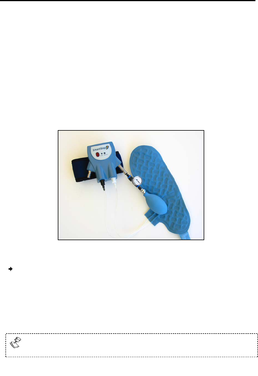
Insole, Control Unit and Air Pump
To inflate the insole:
There are two metal tube sockets, located on each side of the Control Unit.
1. Insert the pump into one socket. Inflate the air pocket. Once the air pocket is
inflated, remove the pump from the socket by pulling the grooved tube
upwards.
2. Repeat the above process for the other socket.
3. Disconnect the insole from the Control Unit.
To disconnect the insole from the Control Unit, twist the connectors counter-
clockwise.

Preparing a Session
Remove the patient’s shoe
SmartStep™ Version 2.1.1 Revision A2 | 49
4.2 Remove the patient’s shoe
Remove the patient’s shoe keeping in mind the following precautions:
SmartStep™ works only with sports shoes.
Patient must wear socks.
Please note that shoe sizes vary according to manufacturers.
The insole must correspond to the size of the patient’s sports shoe.
The insole is personal. Do not transfer it from patient to patient.
4.3 Insert the inflated insole into the shoe
Only one leg at a time undergoes assessment or training. The insole can fit either
foot.
To insert the insole:
Use a sports shoe matching the patient’s leg (left or right). Insert the insole into the
workout shoe ensuring a snug fit, do not remove the original inner insole. The tubes
of the insole should be on the inside (medial side) of the patient’s leg (i.e. on the
patient’s left for a right-foot shoe, or on the patient’s right for a left-foot shoe). If
the tubes are on the other side, turn the insole over.
The insole must fit the shoe properly and smoothly cover the entire inner sole area of
the shoe. If the insole does not fit, try a different size.
SmartStep™
Insole Size (EU)*
SmartStep™
Insole Size (USA)*
37-38 6-7
39-40 7.5-8
41-42 8.5-10
43-44 10.5-11.5
45-46 12-13
* Not all insole sizes are currently available. See section Error! Reference source not
found..
Preparing a Session
Put the patient’s shoe back on
50 | SmartStep™ Verson 2.1.1 Revision A2
4.4 Put the patient’s shoe back on
Use the insole’s extension strip (located at the heel of the insole) as if it were a shoe
horn to prevent the insole from sliding forward. Ask the patient to take a few steps in
order to properly locate the insole inside the shoe.
The patient should feel comfortable when walking and exercising with the insole.
4.5 Attach the Control Unit to the ankle
Attach the Control Unit, using the strap, above the patient’s lateral malleolus
(ankle). The Control Unit should be on the outside of the leg (i.e. on the patient’s
right for a right foot, or on the patient’s left for a left foot). The display should
face outwards so that you can see its readings.
The ankle strap should not touch the patient’s skin. Keep the patient’s sock or
trouser between the skin and the Control Unit.
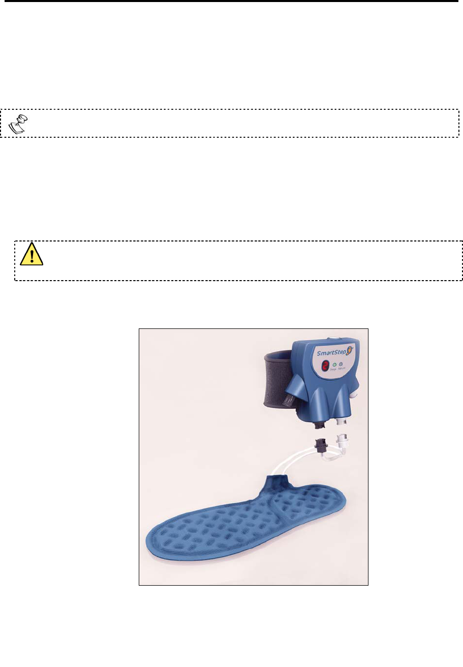
4.6 Connect the insole to the Control Unit
Control Unit and Insole Connection
Preparing a Session
Inserting the Bluetooth USB Adapter
SmartStep™ Version 2.1.1 Revision A2 | 51
1. Connect the insole tubes to the Control Unit by pressing the connectors
together and twisting clockwise.
2. Connect the black connectors together for the hind foot and the white
connectors for the forefoot.
4.7 Inserting the Bluetooth USB Adapter
Insert the Bluetooth USB adapter into the computer, if it has not yet been
inserted.
The Bluetooth icon at the bottom right of the screen is red before the
Bluetooth USB adapter is inserted.
The Bluetooth icon turns white after Bluetooth USB Adapter insertion.
Make sure the adapter is unobstructed and able to broadcast to the Control
Unit. If the adapter is obstructed it is recommended to use a USB extension
cord.
For online exercises the adapter broadcast range is about 7 meter radius. It is
recommended to work inside one room.
4.8 Turn On the Control Unit
Press the Operation button on top of the Control Unit twice.
The Control Unit display is 0.
4.9 Launching the SmartStep™ Software
1. Launch the SmartStep™ software by double-clicking on the desktop shortcut icon
Preparing a Session
Launching the SmartStep™ Software
52 | SmartStep™ Verson 2.1.1 Revision A2
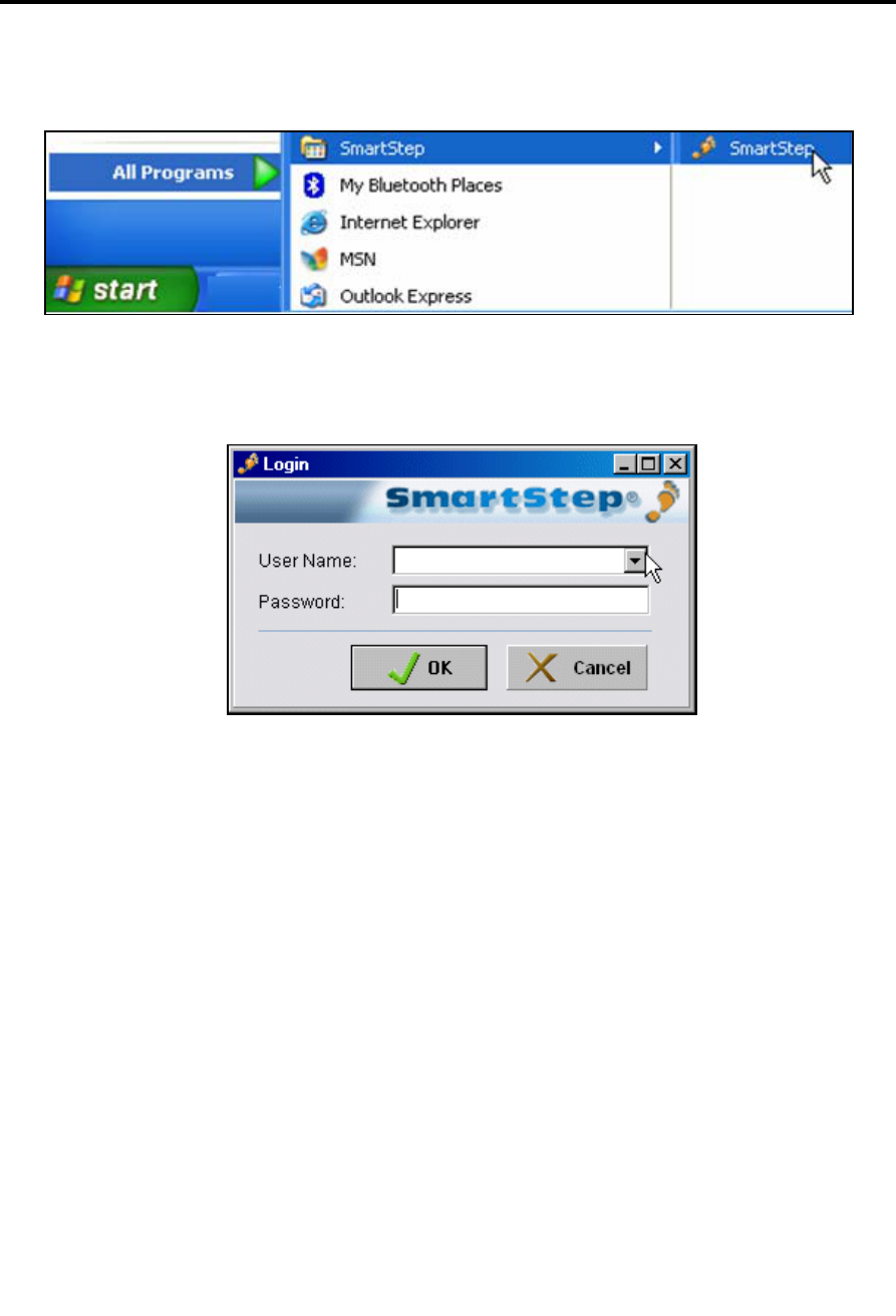
Or by clicking on the SmartStep shortcut in the Start->Program Files->SmartStep
program group.
2. The Login dialog box opens.
3. Select your User Name from the drop-down menu and type your Password in the edit
box.
4. Click the OK button to log in.
Starting a Session
Patient File
SmartStep™ Version 2.1.1 Revision A2 | 53
5 Starting a Session
5.1 Patient File
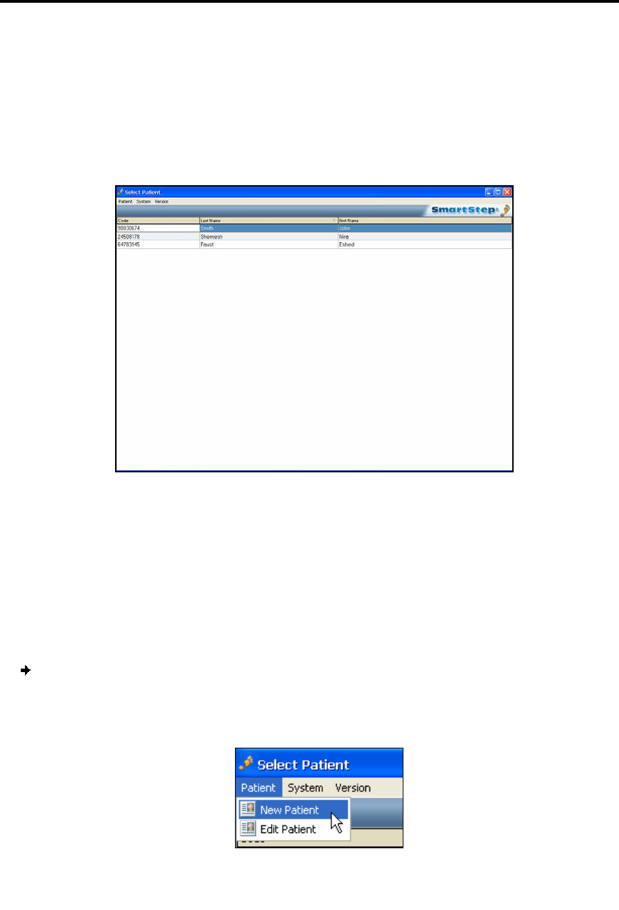
The software starts with a screen listing all past patients.
5.1.1 Creating a New Patient File
For the first session with a new patient, you need to create a patient file. The patient
file holds all administrative data about the patient, as well as historical records of all
the patient’s sessions.
To create a new patient file:
1. In the Select Patient screen, click the Patient menu, select the New Patient option.
Starting a Session
Creating a New Patient File
54 | SmartStep™ Verson 2.1.1 Revision A2
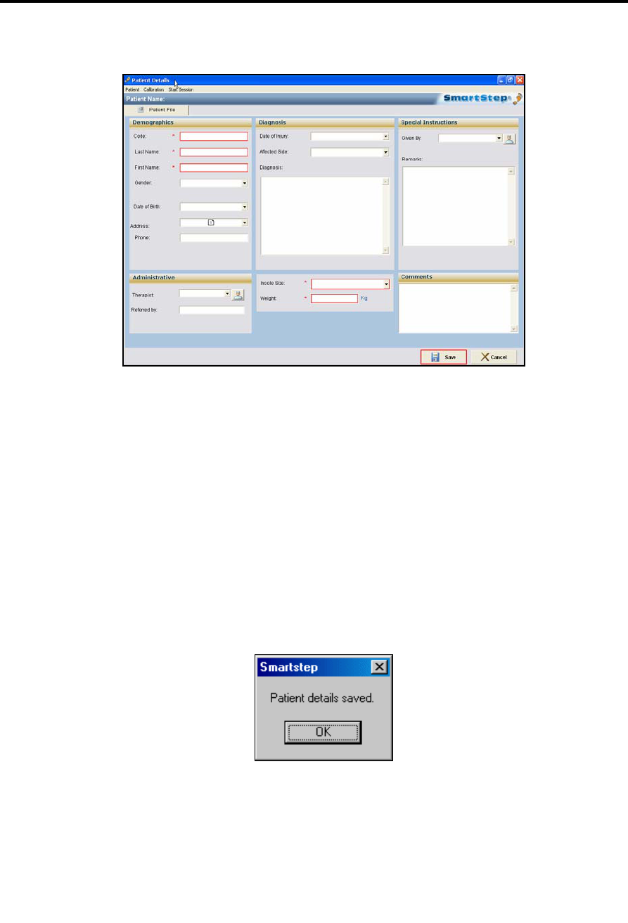
2. The Patient Details dialog box opens.
3. Fill in the patient’s personal and medical details. The following fields, marked with an
asterisk (*) in the dialog box, are mandatory:
Code, a unique reference number.
Last Name
First Name
Insole Size
Weight
4. Click the Save button to save the patient’s details and create a patient file.
A dialog box opens to confirm the action.
5. Click the OK button to continue.
Starting a Session
Opening an Existing Patient File
SmartStep™ Version 2.1.1 Revision A2 | 55
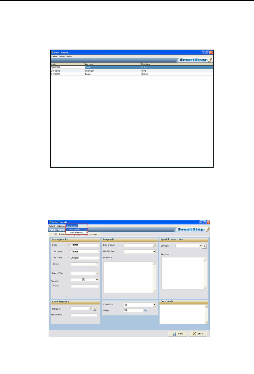
5.1.2 Opening an Existing Patient File
To choose an existing patient, double-click the patient’s line. The patient file opens,
with all previous data recorded.
5.2 Starting a Session
Select Start Session in the Start Session drop-down menu.
In the first session you have to go through the Connect to Bluetooth screen and
the Calibration screen.
Starting a Session
Connecting to the Bluetooth USB Adapter
56 | SmartStep™ Verson 2.1.1 Revision A2
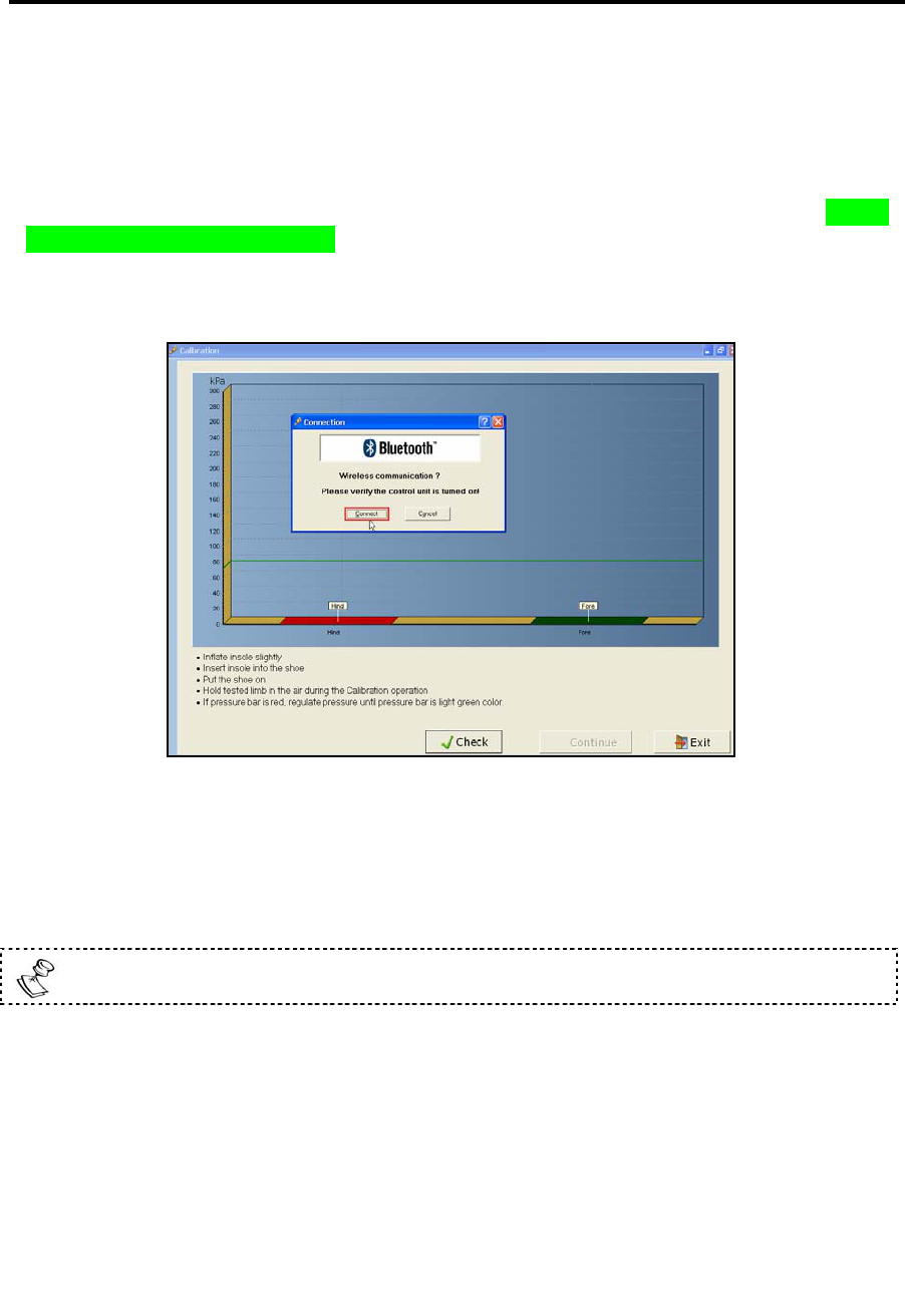
5.3 Connecting to the Bluetooth USB Adapter
This procedure assumes that a Bluetooth USB adapter software is already installed on
the computer. For detailed installation instructions please refer to section Error!
Reference source not found. and Error! Reference source not found..
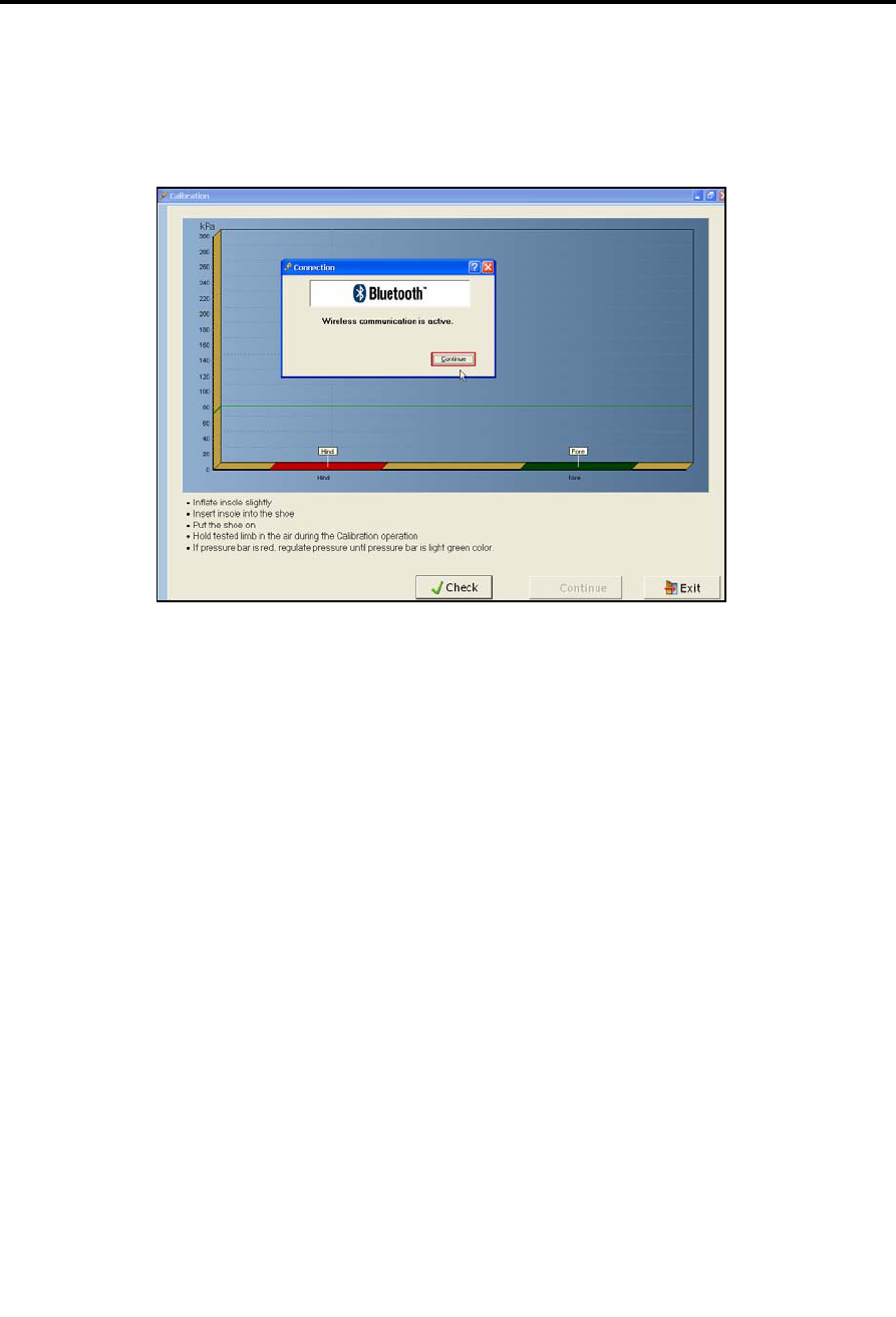
1. Click Connect in the Bluetooth Connection dialog box.
2. The Control Unit beeps twice to indicate that the connection has taken place.
The Bluetooth icon at the bottom of the screen turns green.
3. If the system fails to connect a dialog box allows the user to Try Again.
If the connection fails, at any point during the session, the Control Unit emits
four beeps and the dialog box allows the user to reconnect.
Starting a Session
Performing Calibration
SmartStep™ Version 2.1.1 Revision A2 | 57
4. Click Continue in the Bluetooth Connection dialog box.
5.4 Performing Calibration
At the beginning of each session, SmartStep™ must take a baseline pressure reading,
while the patient is holding his foot in the air. This is called Calibration. When the patient
steps on the foot during the session, the force exerted is compared to this baseline
pressure.
The desktop software checks the air pressure in the insole before the pressure reading is
calibrated. If the pressure is incorrect, the software alerts you and the insole must be
inflated or deflated.
The Calibration window opens automatically once a session is started for a new patient.
It is also possible to begin calibration manually if the user wants to check and correct
the calibration process, by clicking the Calibration button left of the Start Session button.
Starting a Session
Performing Calibration
58 | SmartStep™ Verson 2.1.1 Revision A2
To calibrate the system:
The patient must sit with the treated leg folded over the other leg (or supported by
any other means) in order to avoid any contact of the foot with hard surfaces
throughout this procedure.
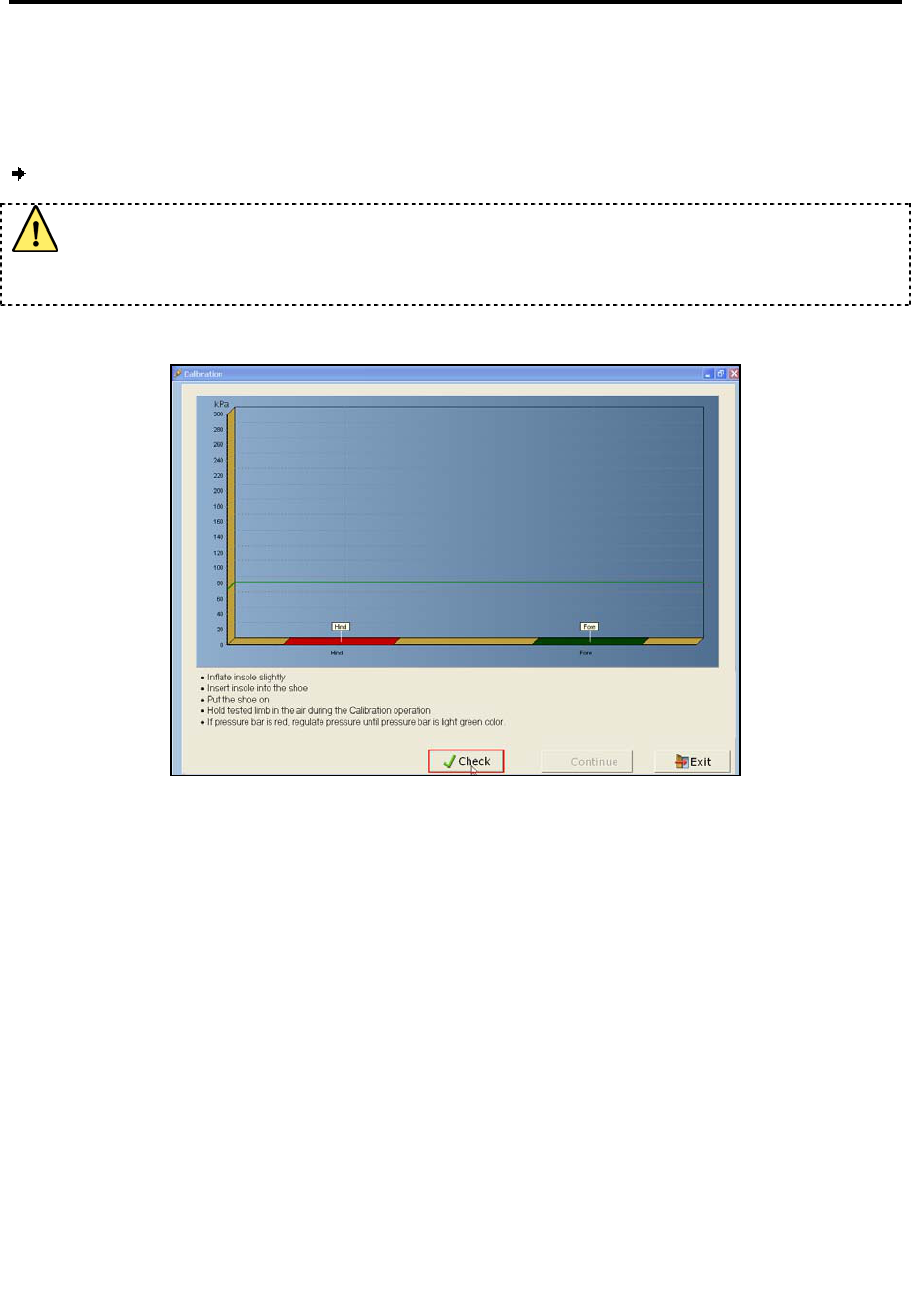
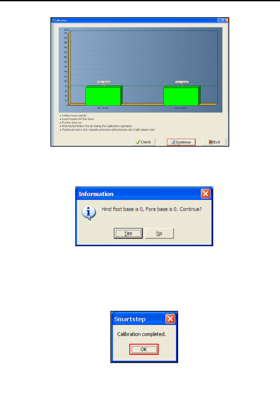
1. In the Calibration screen click Check.
The screen shows two bars: The left-hand bar shows the pressure reading from the
hind foot compartment; the right-hand bar shows the pressure reading for the
forefoot compartment. The horizontal green line represents the optimal pressure
level. The graphs may be above or below the line, indicating that the pressure is too
high or too low. The color of the graph indicates the action you should take.
See section 4.1 for details about inflating the insole. It is possible to deflate the insole
as follows:
o To reduce air pressure slowly, turn the round button on the manual pump
counter-clockwise in a slow and controlled way to regulate air pressure.
o Some users may prefer to deflate all the air, and re-inflate again : turn the
button counter-clockwise until all the air is released. Turn the button clockwise to
shut off air outflow and re-inflate insole.
Starting a Session
Performing Calibration
SmartStep™ Version 2.1.1 Revision A2 | 59
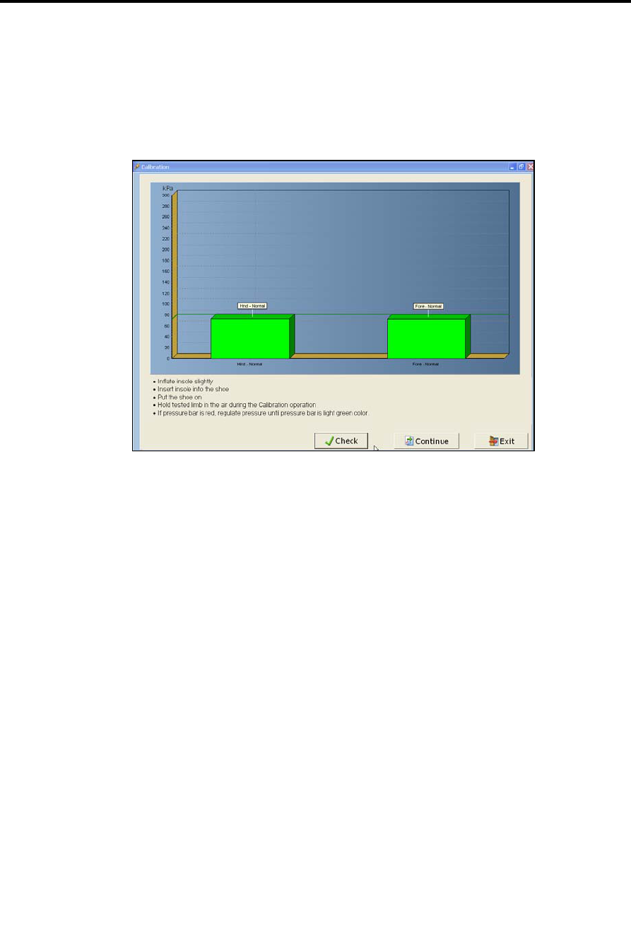
If the graphs are light green, as shown below, air pressure is at the correct
level.
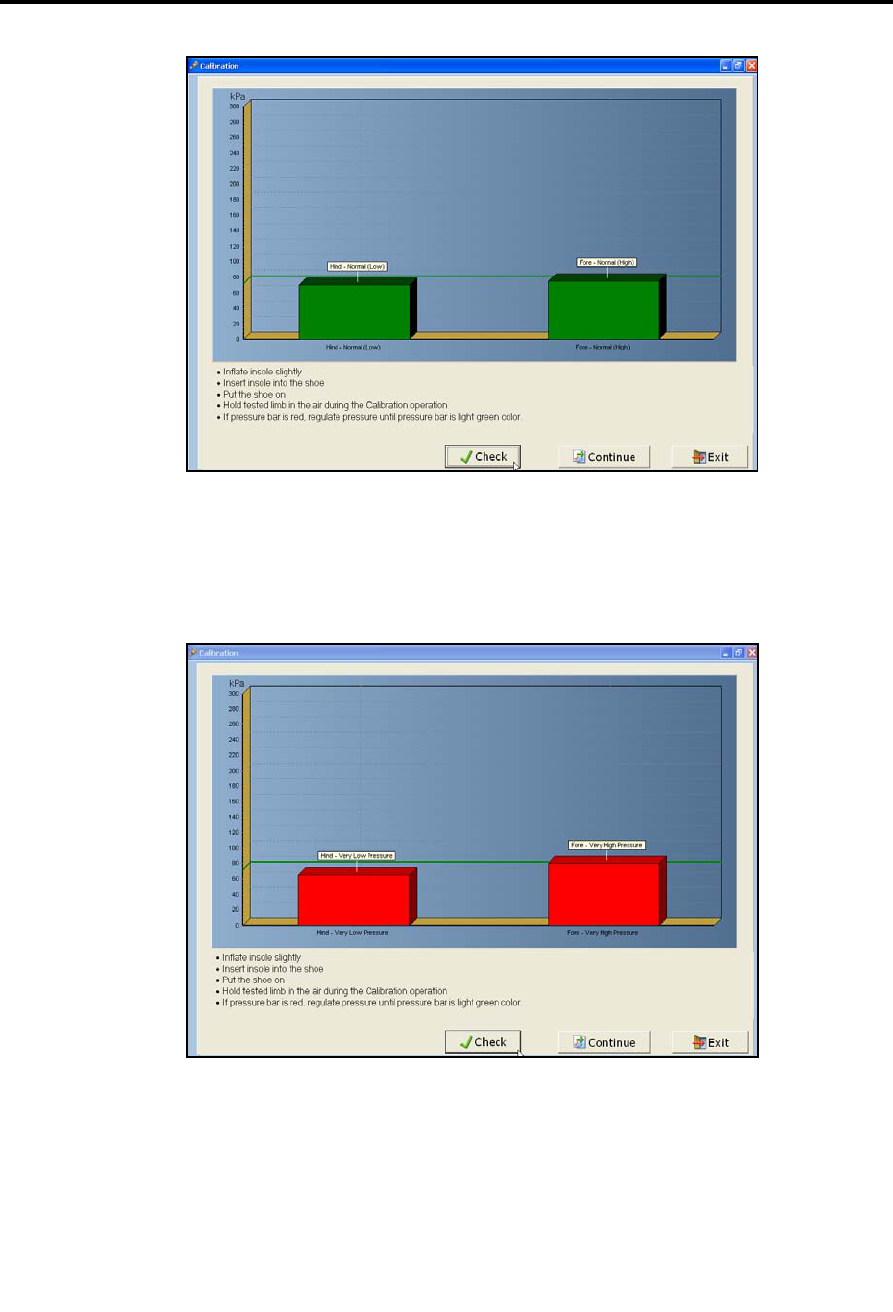
If the graphs are dark green, as shown below, pressure is slightly too low or
too high. Deflate or re-inflate the insole to reach optimal air pressure. You
may proceed to workout, but it is recommended that you achieve optimal
insole air pressure (indicated by light green bars as shown above). If you
choose to continue working with this imprecise air pressure it may affect
system accuracy.
Starting a Session
Performing Calibration
60 | SmartStep™ Verson 2.1.1 Revision A2
The red bar as shown below indicates that the pressure is outside the
permitted range. The system will not allow you to continue. Deflated or re-
inflated The insole as necessary.
2. When you have finished re-inflating the hind and forefoot compartments, check the
pressure reading. If pressure is now at the correct level (the bars are green), click
Continue in the Calibration screen.
Starting a Session
Performing Calibration
SmartStep™ Version 2.1.1 Revision A2 | 61
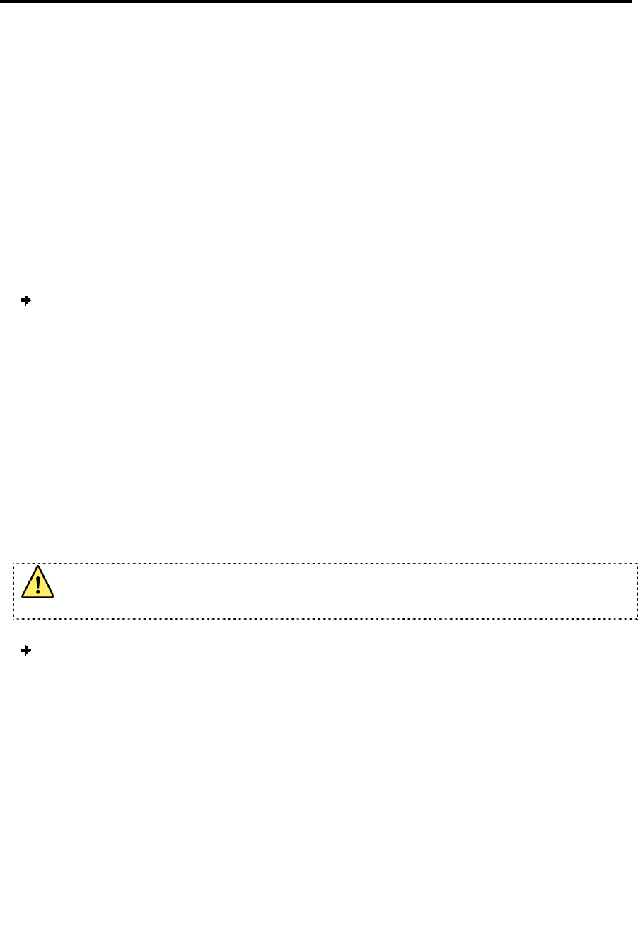
3. A dialog box opens to confirm calibration. The value 0 is the correct pressure
reading.
If values are other than 0, click No and repeat the calibration process. Make sure the
patient foot is relaxed.
4. If values are 0, click Yes.
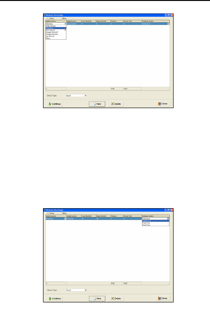
5. A dialog box confirms that Calibration has been completed. Click OK and proceed with
the workout (see section 6 and 7).
6. The Control Unit display shows 1.

Starting a Session
Performing Calibration
62 | SmartStep™ Verson 2.1.1 Revision A2
Online Work
Defining Workout Plan and Operation Mode
SmartStep™ Version 2.1.1 Revision A2 | 63
6 Online Work
You are now ready to define and perform the workout with the patient. Sessions may be
defined as assessment or training. The assessment process is performed without patient
weight bearing limits. It is intended for testing and diagnosis. The training process is
performed with patient weight bearing limits. It is intended for the actual training and
rehabilitation process.
A session may consist of either one exercise or multiple exercises. Select one exercise at
a time in the order in which they are to be performed by the patient.
To define the workout:
1. In the SmartStep™ software, choose an exercise type, define relevant parameters
and set an operation mode (see section 6.1).
2. Define additional exercises for this workout, if needed. These exercises will be
performed immediately after the first one, in the order you define (see section
6.1).
3. Instruct the patient on how to perform the exercise, and start the session (see
section 6.2).
6.1 Defining Workout Plan and Operation Mode
Working online requires the constant communication of the Control Unit with
the computer via the Bluetooth.
To define a workout plan:
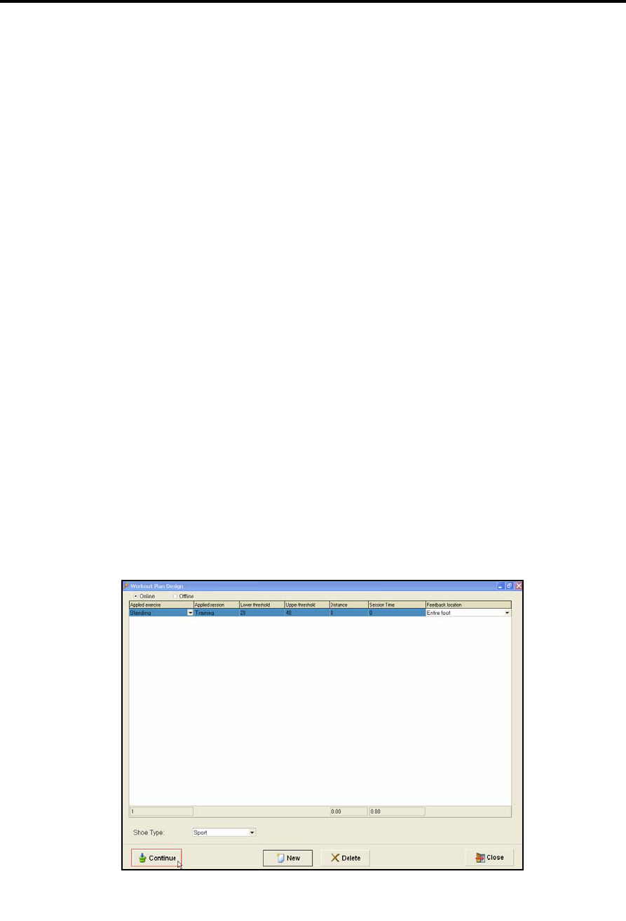
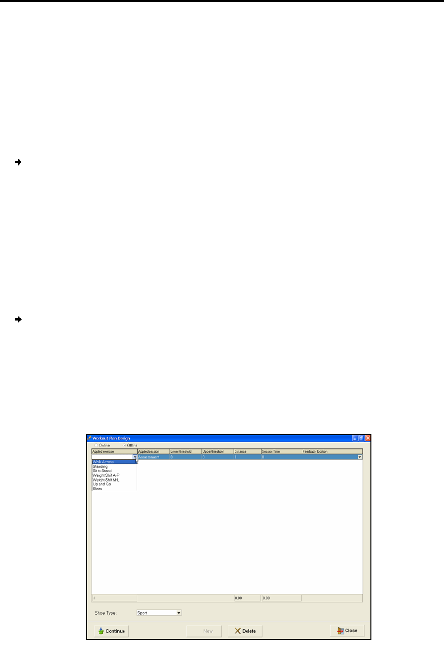
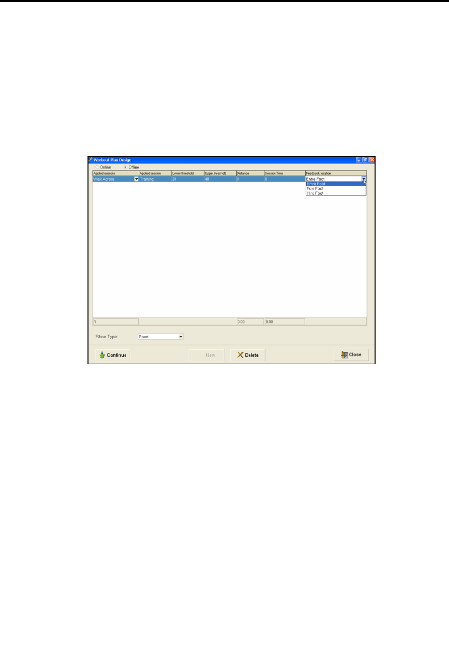
1. The Workout Plan Design screen is opens.
2. Click in the Applied exercise combo box, at the extreme left cell of the table row.
From the drop-down menu, select one of the static exercises: Standing, Sit to Stand,
Weight Shift A-P, or Weight Shift M-L. It is also possible to select one of the dynamic
exercises Walk Across, Up and Go, or Stairs. According to the exercise selected, the
system automatically sets the Online/Offline parameter. Online for static exercises,
Offline for dynamic exercises. The default can be changed by the user.
Online Work
Defining Workout Plan and Operation Mode
64 | SmartStep™ Verson 2.1.1 Revision A2
3. The Applied session column indicates assessment by default.
4. If you are performing an assessment, press the Continue button at the bottom left
corner of the screen and skip to step 12 below.
5. If you are performing training, click in the Lower threshold and Upper threshold
fields and define the desired weight range. The Applied Session changes
automatically from Assessment to Training and the Control Unit display changes to
mode 2.
6. Distance can be defined in m/ft, which allows speed calculations. If the Distance is
not defined, the speed results are 0.
7. If you wish to limit the time of the exercise, enter a period in seconds in the
Session time field. The exercise ends when this time period elapses (you can stop
it manually before the time is up). Leave Session time as 0 if you do not wish to
impose a time limit.
8. If you set up thresholds, you can select the feedback location from the menu.
Online Work
Defining Workout Plan and Operation Mode
SmartStep™ Version 2.1.1 Revision A2 | 65
By default the system provides feedback for the Entire foot, and the Control
Unit beeps once when the patient enters the desired weight range (defined in
the Lower and Upper threshold fields) for the forefoot and hind foot combined.
The Control Unit emits multiple beeps to alert the patient and therapist when
the patient exceeds the defined maximum weight-bearing limit.
Select Forefoot if you want the Control Unit to beep once when the patient
enters the desired weight range (defined in Lower threshold and Upper
threshold fields) with the forefoot only. The Control Unit beeps repeatedly to
alert the patient and therapist when the patient exceeds the defined maximum
weight-bearing limit of the forefoot.
Select Hind foot if you want the Control Unit to beep once when the patient
enters the desired weight range (defined in Lower threshold and Upper
threshold fields) with the hind foot only. The Control Unit beeps repeatedly to
alert the patient and therapist when the patient exceeds the defined maximum
weight-bearing limit of the hind foot.
9. The Shoe Type field is by default always Sport Shoe, as SmartStep™ only works
with sports shoes.
10. If more than one exercise is desired, click the New button to create a new row,
and repeat steps 3 to 9 to define the exercise type and parameters.
11. If you wish to delete an exercise, click to select a row and press the Delete button.
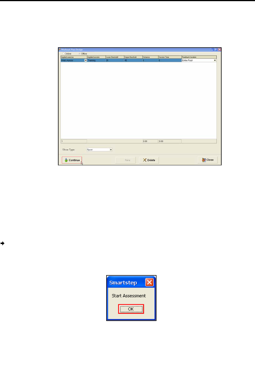
12. When you have finished defining the exercise or exercises, in the Workout Plan
Design screen, click the Continue button to begin.
Online Work
Performing the Workout
66 | SmartStep™ Verson 2.1.1 Revision A2
6.2 Performing the Workout
Once you have defined the workout and set the parameters, you are ready to begin.
To start the session:
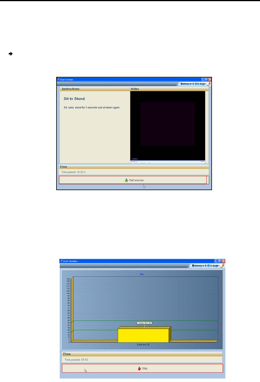
1. Once you click Continue, the Start Session screen opens.
2. The screen displays instructions for performing the exercise, and an instructional
video.
3. Once the instructions have been read and the patient is ready, click the Start Exercise
bar, at the bottom of the screen.
4. During an Online Exercise, the SmartStep™ software displays a dynamic chart, similar
to the image below.
Online Work
Performing the Workout
SmartStep™ Version 2.1.1 Revision A2 | 67
The chart has the following elements:
The vertical axis shows the weight in Kg/lb units.
The yellow bar shows the real-time force exerted on the entire foot.
The dark green horizontal lines mark the lower and upper thresholds of the
desired weight range.
Elapsed time is indicated below the chart.
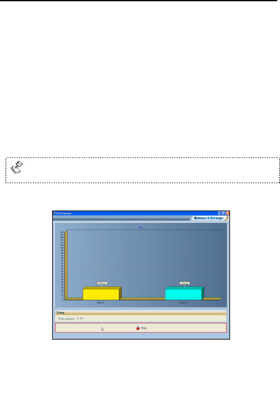
Left-clicking once, anywhere in the chart, switches the Entire bar graph to bars
for hind foot and forefoot.
The yellow bar shows the real-time force exerted on the hind foot.
The light blue bar shows the real-time force exerted on the forefoot.
Online Work
Performing the Workout
68 | SmartStep™ Verson 2.1.1 Revision A2
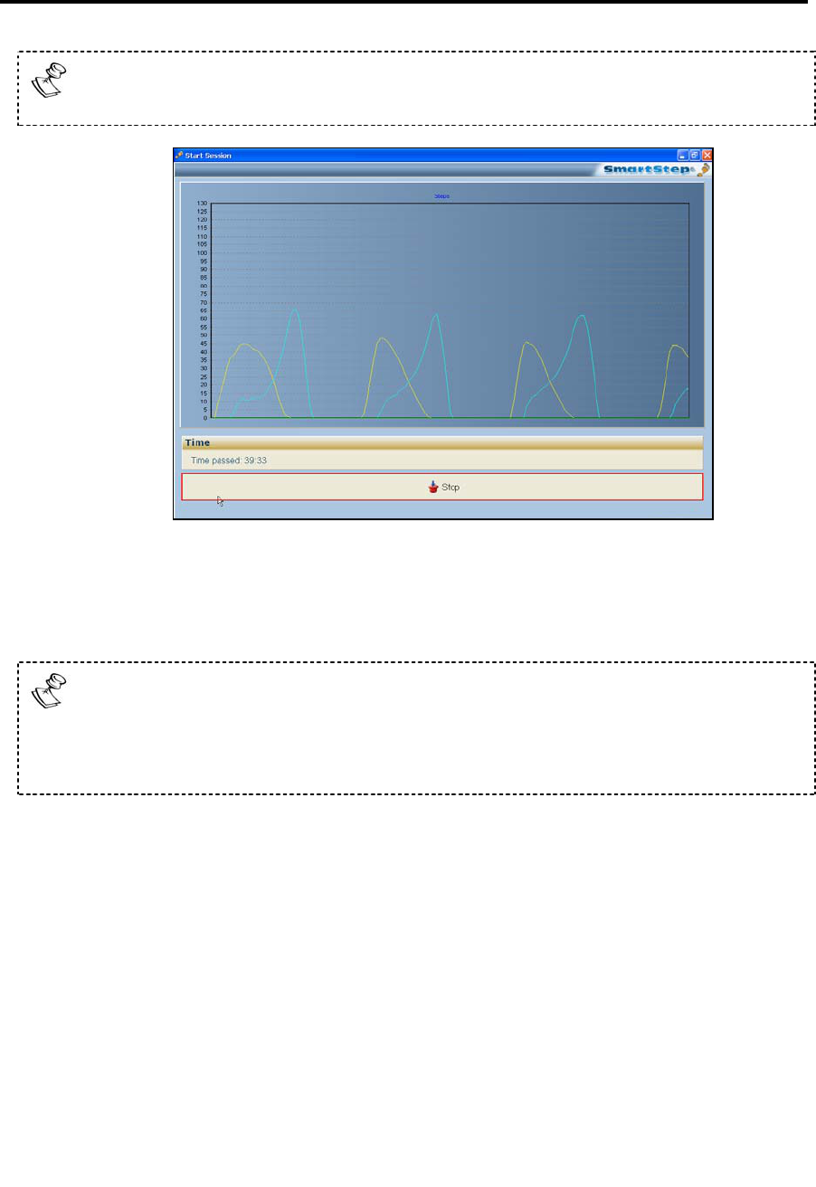
Clicking again switches the hind foot and fore foot bar graph to continuous line
graphs.
The horizontal axis shows time (the extreme-right point is the current time).
The light blue line graph shows the force exerted on the hind foot.
The yellow line graph shows force exerted on the forefoot.
Clicking a third time switches it back.
The above description is correct for static exercise. In case of dynamic ones,
the first graph would be line graph, then a bar graph for the entire foot and
then a bar graph for the hind foot and the forefoot.
5. If Thresholds have been determined, audio feedback is provided:
Silence indicates that the weight the patient is exerting on the insole is under
the Lower Threshold.
One beep indicates that the weight the patient is exerting is between the
Lower and Upper Thresholds.
Multiple beeps indicate that the weight the patient is exerting is above the
Upper Threshold. Therapist intervention may be necessary.
6. To stop the exercise, click the Stop bar at the bottom of the screen.
7. At the end of the exercise the results screen opens.
Offline Work
Defining Workout Plan and Operation Mode
SmartStep™ Version 2.1.1 Revision A2 | 69
7 Offline Work
During an offline work, live visual feedback is not available but you can have audio
feedback. It is possible to store the session data on the Control Unit and download it
later to the computer. This allows you to view session results and statistics on the
SmartStep™ software.
To define the workout:
1. In the SmartStep™ software, choose an exercise type, define the relevant
parameters and set the operation mode (see section 7.1).
2. Instruct the patient on how to perform the exercise, and start the session (see
section 7.2).
3. The Control Unit, if required, can collects data during the session (see section 7.2).
4. Download the data collected, if you have chosen this option (see section 7.3).
7.1 Defining Workout Plan and Operation Mode
To define a workout plan:
1. The Workout Plan Design screen is open.
2. Click the Applied exercise combo box, at the extreme left of the table row. From the
drop-down menu, select one of the dynamic exercises: Walk Across, Up and Go, or
Stairs. You can also select one of the static exercises standing, Sit to Stand, Weight Shift
A-P, or Weight Shift M-L. According to the exercise selected, the system automatically
sets the Online/Offline parameter. Online for static exercises, Offline for dynamic
exercises. The default can be changed by the user.
Offline Work
Defining Workout Plan and Operation Mode
70 | SmartStep™ Verson 2.1.1 Revision A2
3. The Applied Session column is Assessment by default.
4. If you are performing an assessment, Click Continue button at the left corner of
screen and skip to step 8 below.
5. If you are performing training, click in the Lower threshold and Upper threshold fields
and define the desired weight range. The Applied Session automatically changes to
Training and the control unit display changes to mode 2.
6. If you plan to give the patient audio feedback, open the Feedback location combo box.
By default the system provides feedback for the Entire foot, and the Control
Unit beeps when the patient enters the desired weight range (defined in Lower
threshold and Upper threshold) for the fore and heel combined. The Control
Unit beeps repeatedly to alert the patient and therapist when the patient
exceeds the defined maximum weight-bearing limit.
Select Forefoot if you want the Control Unit to beep once when the patient
enters the desired weight range (defined in Lower threshold and Upper
threshold) with the fore foot only. The Control Unit beeps multiple times to
alert the patient and therapist when the patient exceeds the defined maximum
weight-bearing limit of the fore foot.
Select Hind foot if you want the Control Unit to beep once when the patient
enters the desired weight range (defined in Lower threshold and Upper
threshold) with the hind foot only. The Control Unit beeps repeatedly to alert
the patient and therapist when the patient exceeds the defined maximum
weight-bearing limit of the hind foot.
7. The Shoe Type field is by default always Sport, as SmartStep™ only works with sports
shoes.
Offline Work
Performing the Workout
SmartStep™ Version 2.1.1 Revision A2 | 71
8. When you have finished defining the exercise in the Workout Plan Design screen, click
Continue to begin.
7.2 Performing the Workout
Once you have defined the workout and set the parameters, you are ready to begin the
workout.
To start the session:
1. Click OK, and instruct the patient to begin the exercise.
2. If threshold has been determined audio feedback is provided.
5. If you want to collect session data on the Control Unit (so you can download it to the
computer later), press and hold the Operation button for 2 seconds. A dot is added to
the mode number and the unit beeps The dot signifies that data collection is being
performed.
Offline Work
Downloading Data to the Computer
72 | SmartStep™ Verson 2.1.1 Revision A2
6. If you want to stop data collection, press the Operation button once. The dot is
removed from the mode number.
Silence indicates that the weight the patient is exerting on the insole is below
the Lower Threshold.
One beep indicates that the weight the patient is exerting is between the
Lower and Upper Thresholds.
Multiple beeps in quick succession indicate that the weight the patient is
exerting is above the Upper Threshold. Therapist intervention may be
necessary.
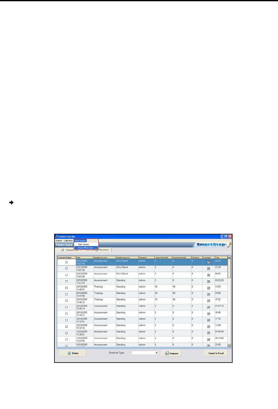
7.3 Downloading Data to the Computer
After the end of the exercise, if you selected an operation mode with data collection
(either 1. with a dot, or 2. with a dot), you can download the data from the Control
Unit to the computer.
To download session data to the computer:
1. In the Patient Details screen, in the Start Session menu, select the Read Offline Data
option.
Offline Work
Downloading Data to the Computer
SmartStep™ Version 2.1.1 Revision A2 | 73
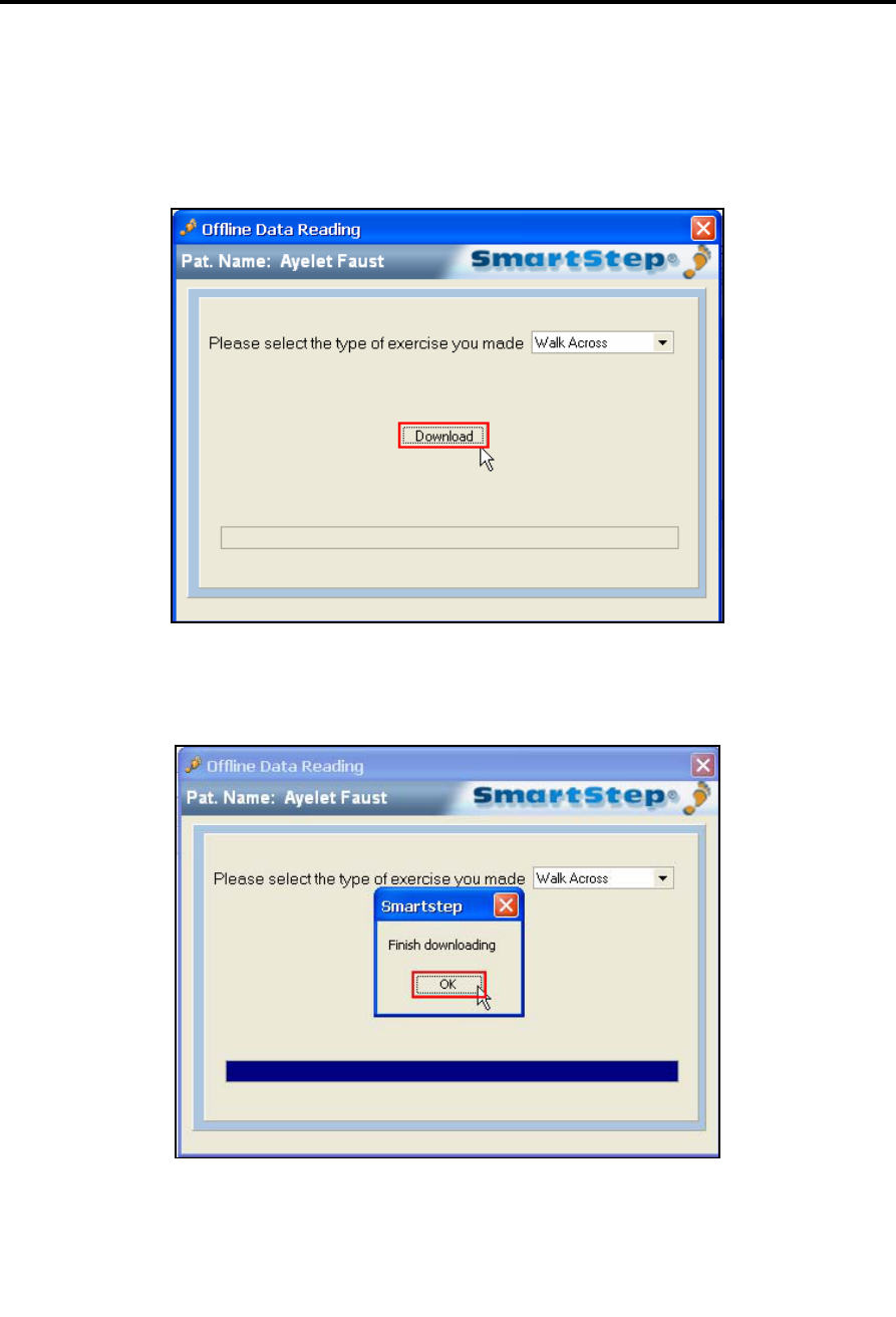
The Offline Data Reading dialog opens.
2. Click the Download button.
3. Click OK.
When download is complete, the operation mode reverts to the last mode before
download began (mode 1 or 2) and the software shows the results screen.

Tracking the Rehabilitation Progress
Opening Previously Recorded Sessions
74 | SmartStep™ Verson 2.1.1 Revision A2
8 Tracking the Rehabilitation Progress
The SmartStep™ system records assessment and training sessions. Historical data is
collected and saved for each patient. This allows easy retrieval of past sessions. This
makes it possible to track the rehabilitation process by analyzing the sessions and
comparing them to other sessions.
The screenshots in this chapter were taken from the European version of the
software and the weight is shown in Kg. In the American version of the software
the weight is shown in lb.
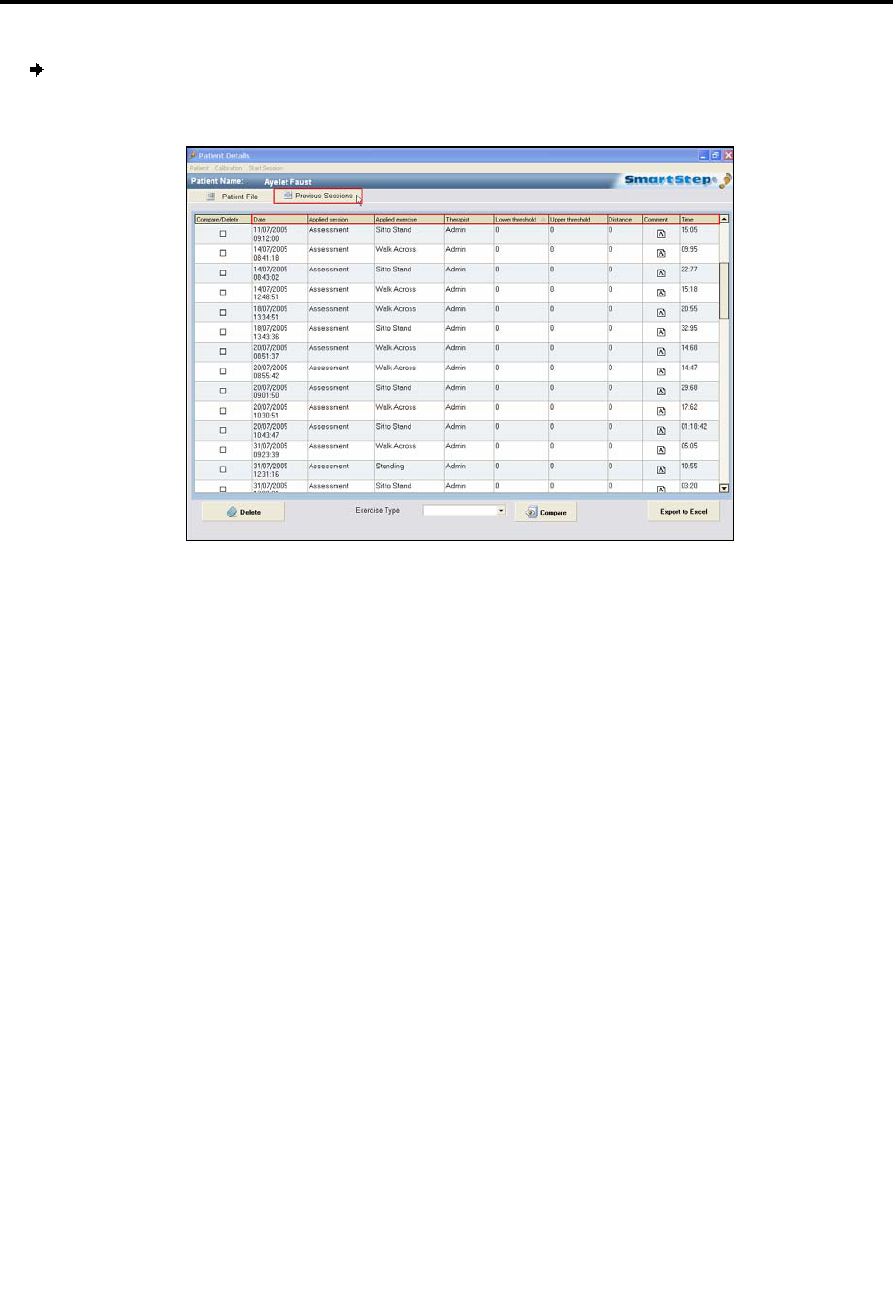
8.1 Opening Previously Recorded Sessions
Online exercises and downloaded offline exercises results are stored in the same
format in the Previous Sessions screen.
1. Open one previous session (see section 8.1 below).
2. Open several sessions and compare them (see section 8.4).
A session is one exercise that was performed by the patient.
Tracking the Rehabilitation Progress
Opening Previously Recorded Sessions
SmartStep™ Version 2.1.1 Revision A2 | 75
To open a previously recorded session:
1. In the Patient Details screen, click the Previous Sessions tab.
2. To find the session you need, you can:
Sort the list by any parameter, by clicking the relevant column’s header.
Select an Exercise Type, from the drop-down menu at the bottom of the
screen, to only view sessions with that exercise type. You can view all exercise
by choosing Clear Filter in the drop-down menu. To view a different exercise
select it from the drop-down menu.
3. Double-click on a session to view the results.
The Results tab screen opens, displaying session statistics. See section 8.2 to learn
more about statistics for a single session.
Tracking the Rehabilitation Progress
Understanding Session Results
76 | SmartStep™ Verson 2.1.1 Revision A2
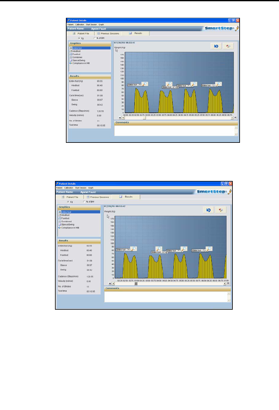
8.2 Understanding Session Results
The Results tab, shown above, appears automatically at the end of the online session,
after downloading of offline session data or after double click the specific session at
the previous session screen. The following sections explain how to access and
interpret session information.
8.2.1 Switching Between Absolute and Relative Weight
The radio buttons, at the top left of the Results screen, allow you to toggle between
absolute weight (Kg/lb) and weight relative to the patient’s body weight (% of BW).
Tracking the Rehabilitation Progress
Charts
SmartStep™ Version 2.1.1 Revision A2 | 77
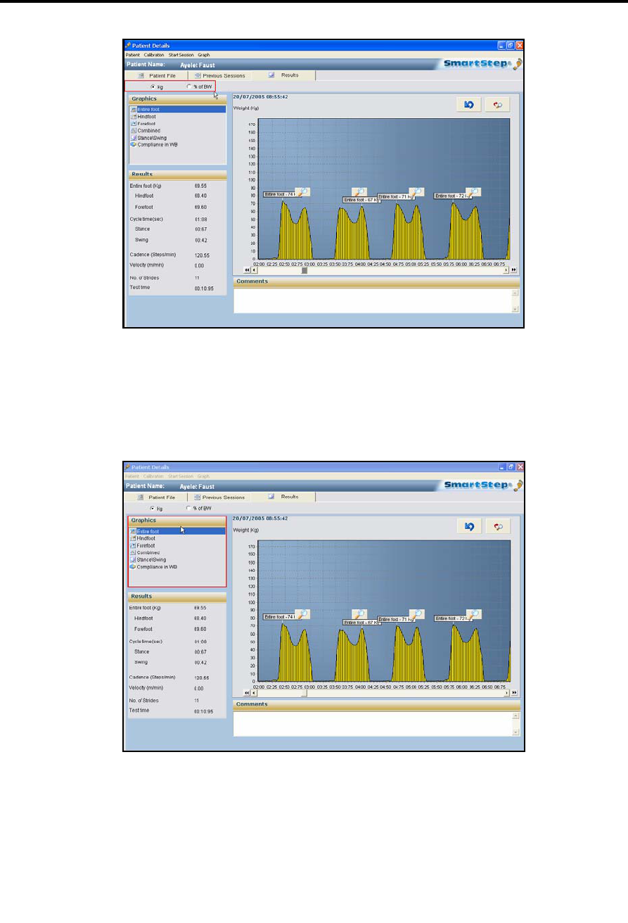
8.2.2 Charts
The Graphics area, in the top left of the Results tab screen provides a list of charts.
Clicking a chart’s name displays the chart.
The following table lists, describes and shows the charts available.
Tracking the Rehabilitation Progress
Statistics
78 | SmartStep™ Verson 2.1.1 Revision A2
Chart Description
Entire Foot Weight exerted on the entire foot. Weight (absolute or percentage) is displayed vertically,
while time is displayed horizontally. Use the scroll bar at the bottom of the chart to
proceed from the beginning (left) to the end (right) of the session.
Hind foot Weight exerted on the hind foot is displayed in yellow. Weight (absolute or percentage) is
displayed vertically, while time is displayed horizontally. Use the scroll bar at the bottom
of the chart to proceed from the beginning (left) to the end (right) of the session.
Forefoot Weight exerted on the forefoot is displayed in blue. Weight (absolute or percentage) is
displayed vertically, while time is displayed horizontally. Use the scroll bar at the bottom
of the chart to proceed from the beginning (left) to the end (right) of the session.
Combined Weight exerted on the hind foot is displayed in yellow and on the forefoot in blue.
Stance/Swing Shows the percentage of time the patient spent in stance and swing during dynamic
exercises. Absolute time (in seconds) is also displayed.
Compliance in
WB
Shows patient compliance in dynamic exercises. Compliance is displayed as a percentage
of the total steps when the maximum weight on the whole leg was in compliance with the
Lower and Upper weight thresholds.
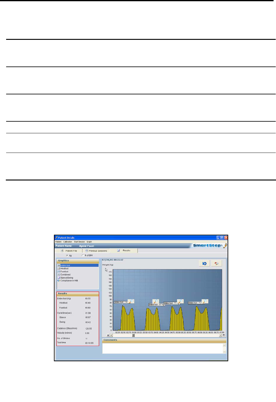
8.2.3 Statistics
The Results area, at the bottom-left of the Results tab, provides a list of aggregate
statistics for the session.
Dynamic Exercise Results (as shown above)
Tracking the Rehabilitation Progress
Viewing Stance/Swing Composition for Specific Steps
SmartStep™ Version 2.1.1 Revision A2 | 79
Statistic Units Description
Entire Foot Kg/lb Average weight exerted on the entire foot during the session.
Forefoot Kg/lb Average weight exerted on the forefoot during the session.
Hind foot Kg/lb Average weight exerted on the hind foot during the session.
Cycle Time Sec Average gait cycle time (stance + swing).
Stance Sec Average stance time in seconds.
Swing Sec Average swing time in seconds.
Cadence Steps/min Number of patient’s steps a minute.
Velocity m / min or ft / min Patient’s velocity.
No. of Strides Strides Number of strides the patient took in the session.
Test time min/sec Session time.
Static Exercise Results
Statistic Units Description
Entire Foot Kg/lb Peak weight exerted on the entire foot during the session.
Forefoot Kg/lb Peak weight exerted on the forefoot during the session.
Hind foot Kg/lb Peak weight exerted on the hind foot during the session.
Test time min/sec Session time.
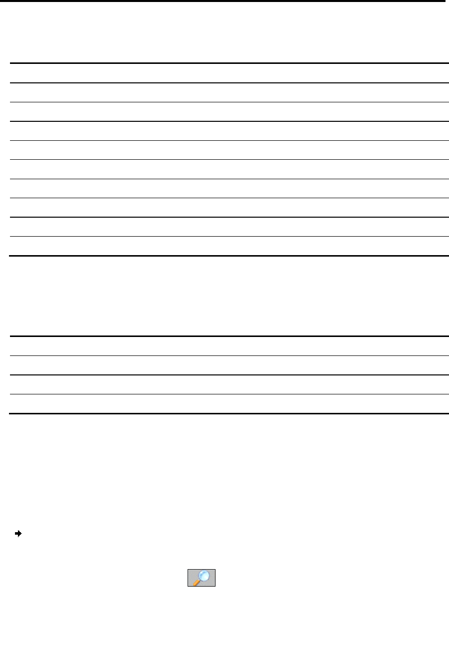
8.2.4 Viewing Stance/Swing Composition for Specific Steps
All the continuous-data charts (Entire Foot, Forefoot, Hind foot and Combined) allow
you to view the stance/swing time composition of specific steps taken by the patient.
To view stance/swing compositions for steps:
1. Scroll left or right to view the step that interests you.
2. Click the magnifying glass icon above the step.
Tracking the Rehabilitation Progress
Viewing Stance/Swing Composition for Specific Steps
80 | SmartStep™ Verson 2.1.1 Revision A2
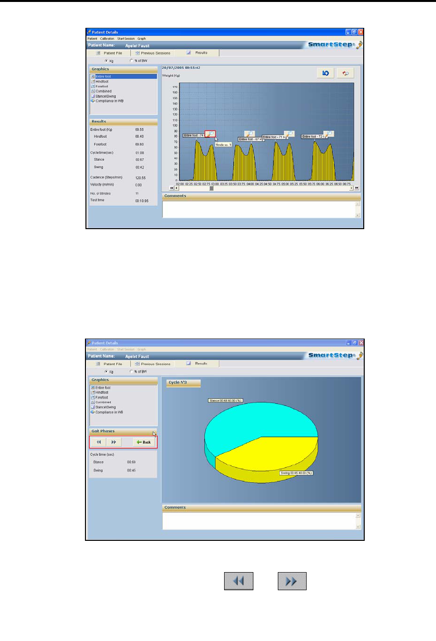
3. The total stance time, the total swing time and their percentage of the total session
time is shown as a pie chart. The cycle number is displayed in the top-left corner.
In the Gait Phases area on the left, use the and buttons to display the
previous or next cycles, or click Back to go to the first step.

Tracking the Rehabilitation Progress
Comments
SmartStep™ Version 2.1.1 Revision A2 | 81
8.2.5 Comments
It is possible to type comments at the bottom of the graph screens. When you exit
the screen, a dialog box will ask you if you want to save the comment.
8.3 Manipulating Session Charts
The Graph menu, found on the main menu bar in the Results screen, has several options
that allow you to manipulate the session charts
1. Zoom (see section 8.3.1)
2. Measure Time (see section 8.3.2)
3. Measure Weight (see section 8.3.3)
4. Edit (see section 8.3.4)
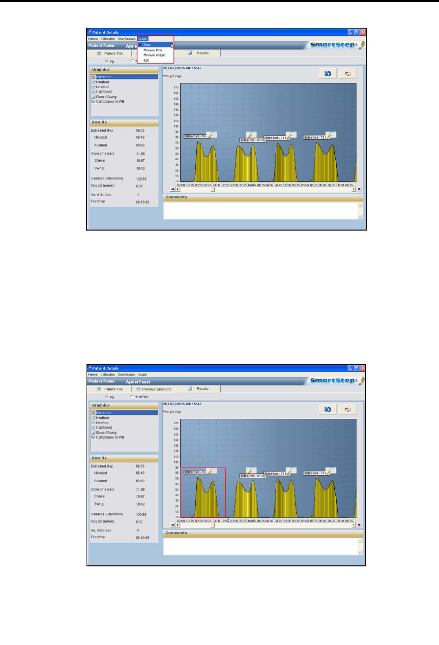
8.3.1 Zooming In and Out
To zoom in on a graph:
1. In the Graph menu, select the Zoom option.
Tracking the Rehabilitation Progress
Zooming In and Out
82 | SmartStep™ Verson 2.1.1 Revision A2
2. Drag the mouse cursor to draw a rectangle from the upper left point to the lower
right point of the area in the graph you wish to magnify. The selected area appears
in detail.
Tracking the Rehabilitation Progress
Measuring Time
SmartStep™ Version 2.1.1 Revision A2 | 83
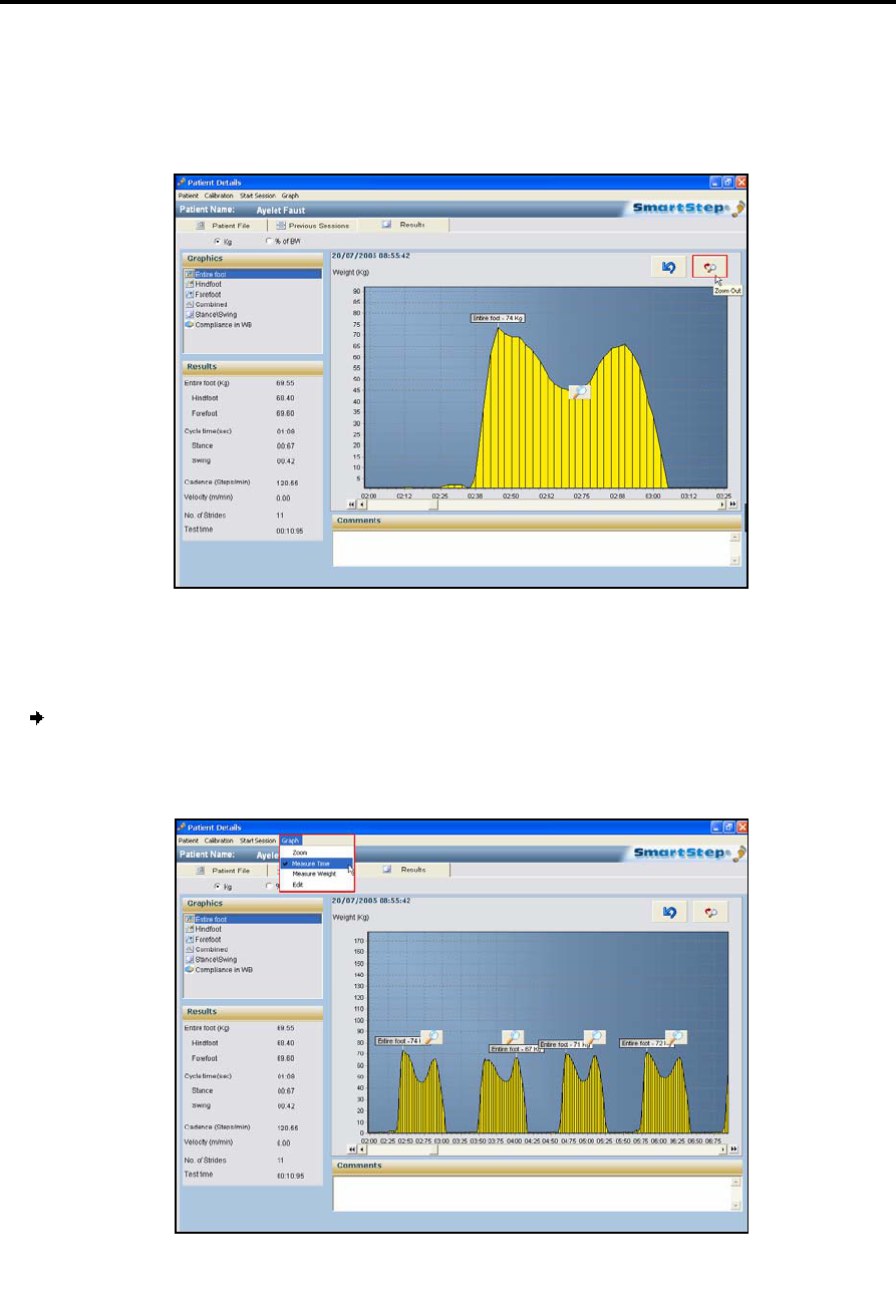
3. To return to the previous full graph view click Zoom Out, or drag the mouse curser
to draw a rectangle from the lower right point to the upper left point at any screen
location.
8.3.2 Measuring Time
To measure time between two points:
1. To obtain a measurement of the time between two points, in the Graph menu,
select the Measure Time option.
Tracking the Rehabilitation Progress
Measuring Weight
84 | SmartStep™ Verson 2.1.1 Revision A2
2. In the graph, click on the start point of the period you wish to measure, and drag
the cursor to the end point.
A dialog box opens that displays the time in seconds between the two points.
3. Click OK to return to graph.
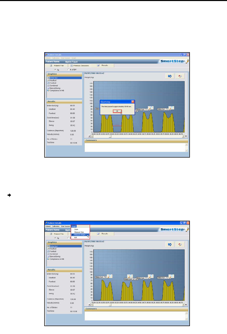
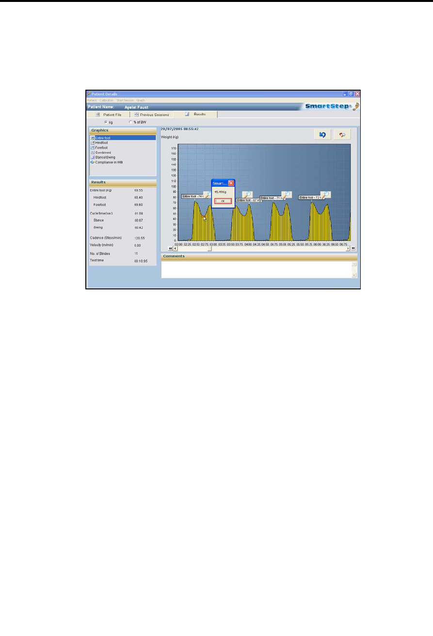
8.3.3 Measuring Weight
To measure weight:
1. To obtain a weight measurement at a given point, from the Graph menu, select the
Measure Weight option.
Tracking the Rehabilitation Progress
Erasing Session Segments
SmartStep™ Version 2.1.1 Revision A2 | 85
2. In the graph, click on the point at which you wish to measure the weight.
A dialog box opens that displays the weight at the selected point.
3. Click the OK button to return to graph.
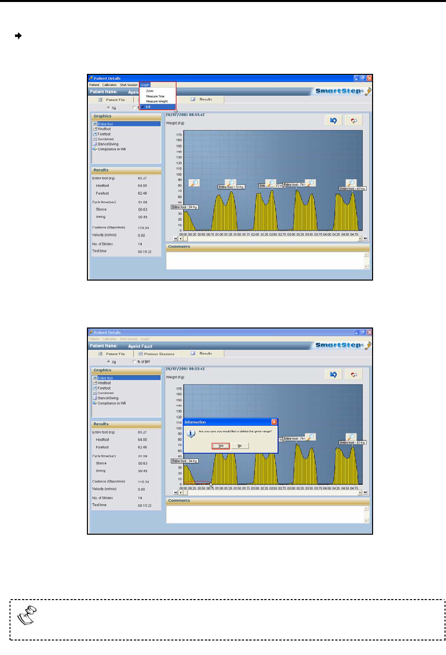
8.3.4 Erasing Session Segments
This option may be used to erase noise at the beginning or end of the session, or
inactivity in the middle, for example if the patient has stopped performing the
exercise. All session data are backed up, so the session can be recovered if parts of it
are erroneously erased.
Tracking the Rehabilitation Progress
Erasing Session Segments
86 | SmartStep™ Verson 2.1.1 Revision A2
To erase session segments:
1. In the Graph menu, select Edit.
2. In the graph, click on the start point of the period you wish to erase, and drag the
cursor to another point.
3. A window opens to confirm deletion. Click Yes to delete.
This action does not affect the database. Information is deleted from the
display window only.
Tracking the Rehabilitation Progress
Comparison Statistics
SmartStep™ Version 2.1.1 Revision A2 | 87
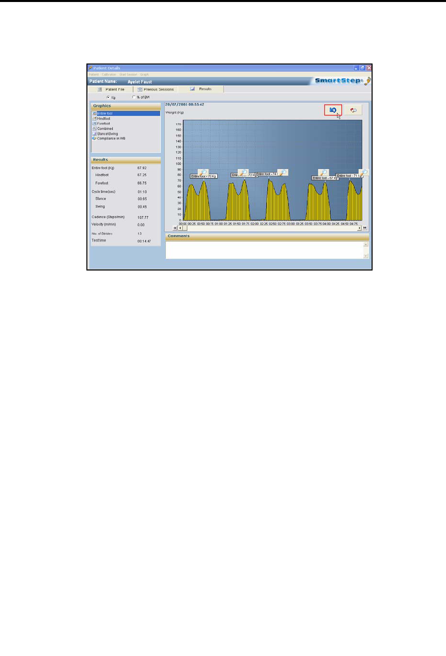
4. You can always restore deleted data by clicking the Undo button.
8.4 Comparison Statistics
The SmartStep™ enable to compare one parameter at a time. Each bar at the
Results tab screen represents a different session.
Tracking the Rehabilitation Progress
Comparison Statistics
88 | SmartStep™ Verson 2.1.1 Revision A2
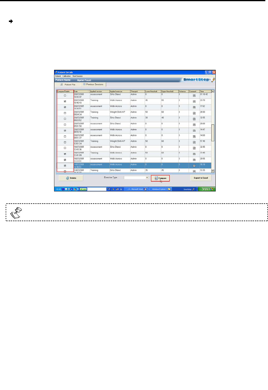
To open several sessions:
1. In the Previous Sessions screen, find the sessions you want to compare (up to six
session), and click the relevant checkboxes in the Compare/Delete column.
You may only compare sessions consisting of the same exercise.
2. Click the Compare button, at the bottom of the screen.
Tracking the Rehabilitation Progress
Comparison Statistics
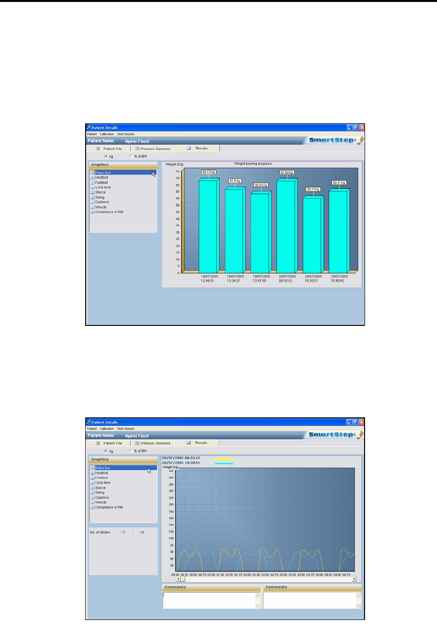
SmartStep™ Version 2.1.1 Revision A2 | 89
The Results tab screen opens, showing the comparison statistics in bars, for the
sessions you selected.
Move between comparison graph by clicking on the relevant graphic option on the
left side of the screen.
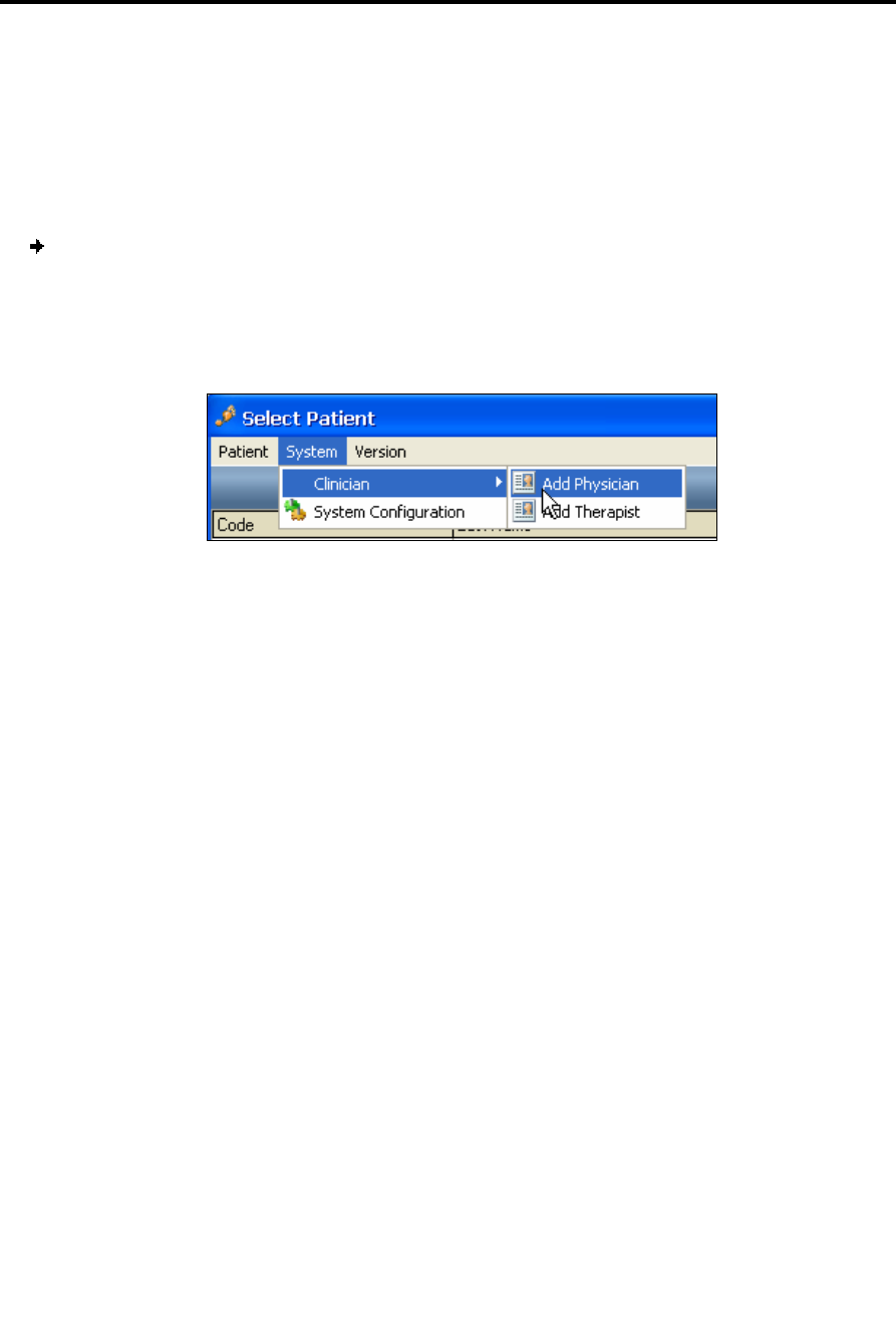
3. By double click the screen, a line comparison graph is available only for the entire
foot and only for two sessions. In the line graph, one session would be represented
by a blue line and the other by a yellow line, with the session dates marked
respectively.

Tracking the Rehabilitation Progress
Session Deletion
90 | SmartStep™ Verson 2.1.1 Revision A2
8.5 Session Deletion
In the Previous Sessions screen, click the relevant checkboxes in the
Compare/Delete column. Click the Delete button bellow. Click OK to confirm.

Turning the Control Unit Off
Session Deletion
SmartStep™ Version 2.1.1 Revision A2 | 91
9 Turning the Control Unit Off
At the end of the session:
Press the Operation Button, to move between modes (1-4) until the unit is
switched off.
Or turn the Control Unit off by pressing the Operation Button continuously.
Maintenance and Administration
Creating Users and Changing Passwords
92 | SmartStep™ Verson 2.1.1 Revision A2
10 Maintenance and Administration
10.1 Creating Users and Changing Passwords
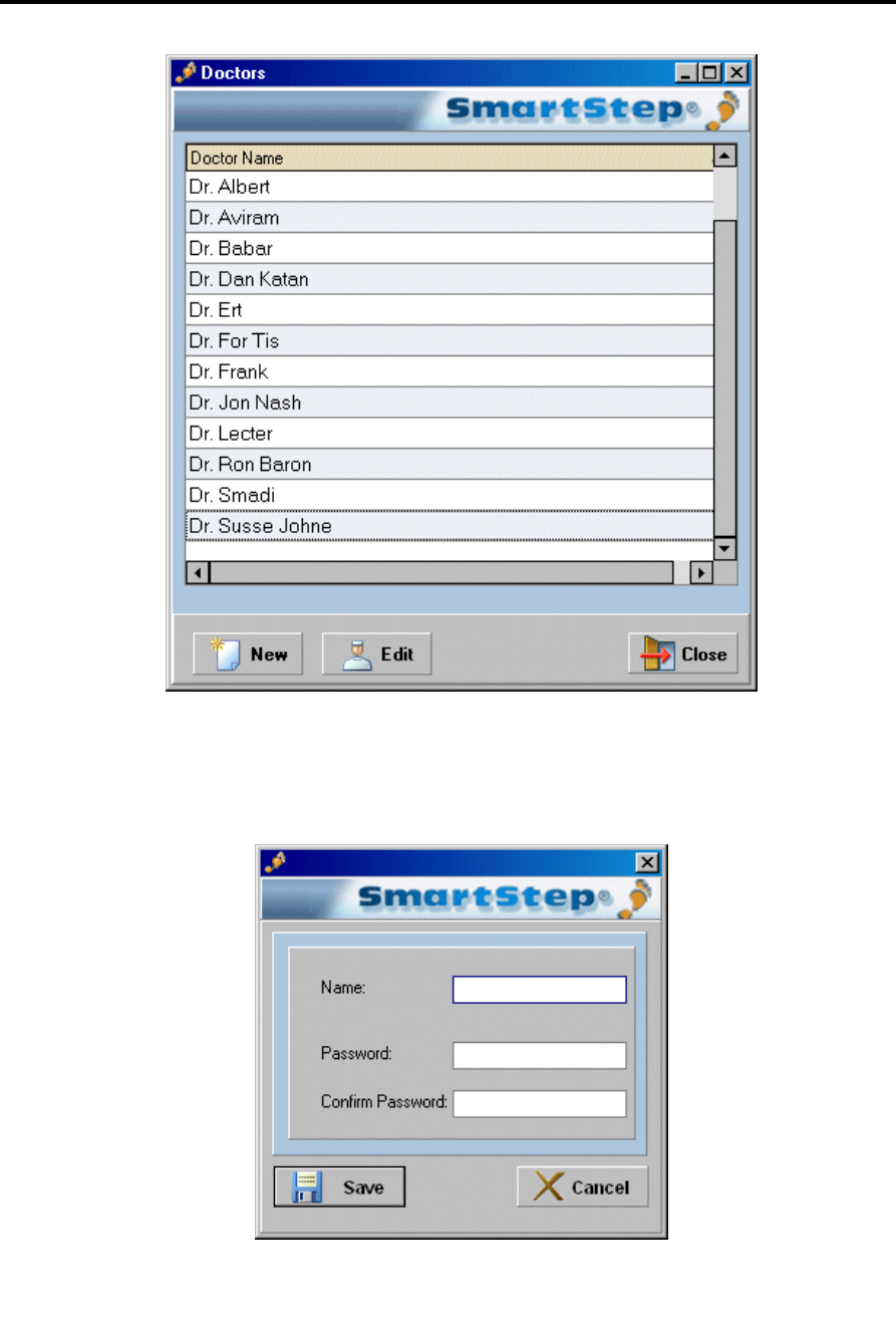
To create a new user:
1. In the System menu, in the Select Patient screen, select the Clinician option.
2. In the submenu, choose either the Add Physician or Add Therapist option.
The current list opens.
Maintenance and Administration
Creating Users and Changing Passwords
SmartStep™ Version 2.1.1 Revision A2 | 93
3. Click the New button to add a new doctor or therapist.
The following dialog box opens.
Maintenance and Administration
Recharging Batteries
94 | SmartStep™ Verson 2.1.1 Revision A2
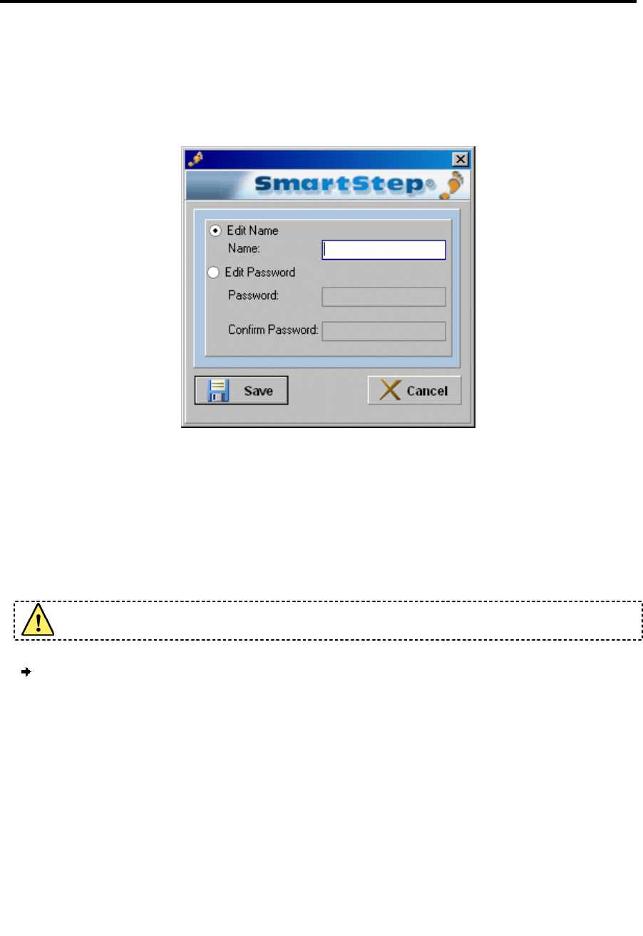
4. Enter the user name, create and confirm a password, and click the Save button.
5. If you wish to edit a currently existing user, click the Edit button in the list of
doctors and therapists.
The edit user dialog opens.
6. Edit the user name or password (and confirm), and click Save.
10.2 Recharging Batteries
You must charge the battery when the Battery Status indicator on the Control Unit
lights up in orange.
You may only use the battery charger supplied with your SmartStep™ System.
To recharge the battery:
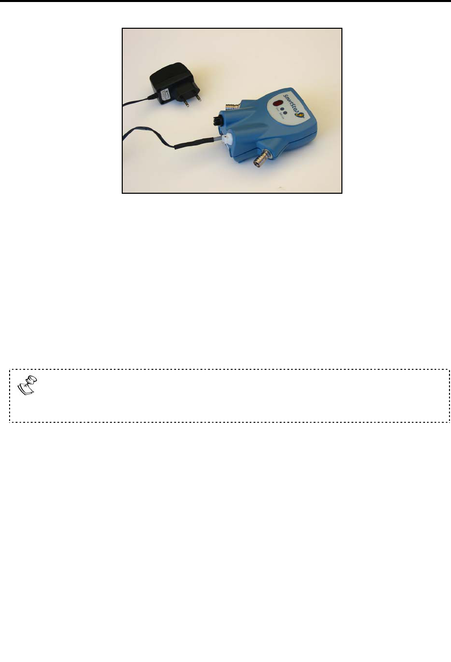
1. Remove the Control Unit from the leg and make sure the unit is off. See chapter 9.
2. Lightly release the inner Velcro strap and remove the protective plastic cover from
the bottom of the unit. Plug the battery charger cable connector into the socket at
the bottom of the unit.
Maintenance and Administration
Recharging Batteries
SmartStep™ Version 2.1.1 Revision A2 | 95
3. Plug the battery charger line connector into an electrical outlet, the green light
appears.
4. Battery charging indicator is green while the battery is charging.
5. Do not disconnect the charger until the battery is fully charged. This takes at least
10 hours, if the battery is completely empty.
6. Once the battery is fully charged, unplug the battery charger from the wall
electrical outlet.
7. Disconnect the battery charger connector from the socket at the bottom of the
Control Unit.
If the Control Unit does not run for at least three hours after it has been
charged, try charging the battery again. If, after re-charging, the unit runs for
less than three hours, contact your Andante dealer.

Troubleshooting
Recharging Batteries
96 | SmartStep™ Verson 2.1.1 Revision A2
11 Troubleshooting
The following sections outline common problems and suggest how to solve them. If you
encounter a problem that is not listed below, please contact your Andante dealer.
Control Unit
Problem
Description
Reason Solution
Operation Button pressed once. Press the Operation Button twice.
Control Unit does not switch on.
Battery is depleted. Charge the Control Unit, according to
manufacturer instructions. See User’s
Guide.
Insole air pressure is incorrect -
Calibration did not take place.
Inflate Insole to correct air pressure. Display shows E and the Control
Unit beeps.
Treated leg was not in the air -
Calibration did not take place.
Make sure treated leg is in the air
during Calibration.
Display shows C and the Control
Unit beeps.
Wireless connection was lost. Return to wireless range and click
Connect.
Display shows S and the Control
Unit beeps.
Sensor problem. Contact the Andante dealer.
Display shows P and the Control
Unit beeps.
Insole is deflated. Inflate the insole, using the pump.
If the problem persists, change insole.
Control Unit beeps and switches
off after the Display shows P.
Insole is substantially deflated. Change insole.
Display shows H and the Control
Unit beeps.
System exceeded maximum
values.
Wait 10 seconds to continue work.
Or
To continue working immediately
press the Operation Button.
Control Unit beeps and switches
off after the Display shows L.
Battery is depleted. Charge the Control Unit, according to
manufacturer instructions. See User’s
Guide.
Control Unit is not in mode 2. Switch to mode 2. No audio feedback.
Weight thresholds were not
broadcasted to the Control Unit.
Repeat weight threshold broadcast.

Troubleshooting
Recharging Batteries
SmartStep™ Version 2.1.1 Revision A2 | 97
Software
Problem Description Reason Solution
Pressure bar is red after inserting
the insole into the shoe.
Pressure outside threshold
boundaries.
Inflate insole to correct air pressure.
An error message during Calibration:
Reset Failed.
The Control Unit is off. Turn the Control Unit on and click
Check.
The insole inflated pressure is
incorrect and the system
failed to Calibration.
Inflate insole to correct air pressure,
reconnect to Control Unit and click
Check.
An error message during the
calibration: Reset Failed and the
Control Unit is beeping and
displaying an E. Treated leg was not in the air
- Calibration did not take
place.
Make sure treated leg is in the air
during Calibration.
An error message during data
transfer: Could not start session: Run
Calibration again.
The Control Unit is off. Turn on the Control Unit and repeat
the Calibration process.
An error message during download:
Could not read from unit. Please try
again.
The Control Unit is off. Turn on the Control Unit, repeat the
Calibration process and click
Download.
The Control Unit is off. Turn on the Control Unit and click on
Connect.
The COM port configuration is
wrong.
Change the COM port configuration,
repeat the Calibration process and
click Connect.
The Bluetooth Adapter is not
connected to the computer
(red icon).
Connect the Bluetooth Adapter to the
computer. Make sure that the icon
color changed to white. Click
Connect.
Connection message: Wireless
Communication?
The Control Unit is outside the
wireless range.
Return to wireless range and click
Connect.

Troubleshooting
Replacement Parts Order Form
98 | SmartStep™ Verson 2.1.1 Revision A2
Parts and Accessories
Replacement Parts Order Form
Please send this form by fax or mail to your local SmartStep™ dealer.
Part Catalogue No. Quantity Required Comments
Insole (European size 37/38, US size 6/7) 20-05-37
Insole (European size 41/42, US size 8.5/10) 22-05-41
Insole (European size 43/44, US size 10.5/11.5) 23-05-43
User’s Guide V2.1.1 80-20
Quick Guide V2.1.1 80-21
Battery charger (EU) 40-37
Battery charger (USA) 40-36
Manual pump 50-30
Bluetooth USB adapter 40-68
Control Unit revision A2 40-07
Control Unit Strap 60-11-01