Andante Medical Devices SMARTSTEP0106 Bluetooth Transmitter User Manual 1
Andante Medical Devices Ltd. Bluetooth Transmitter 1
Contents
- 1. User Manual 1
- 2. User Manual 2
User Manual 1
SmartStep™ Clinic
User’s Manual
Andante Medical Devices Ltd
© Andante Medical Devices Ltd
http://www.andante.co.il

Legal Notice
2 | SmartStep™ Version 2.1.1 Revision A2
Legal Notice
This manual contains information that is proprietary to Andante Medical Devices Ltd.
(“Andante”). No part of this publication may be reproduced in any form without prior
written approval by Andante.
Right, title and interest, all information, copyrights, patents, know-how, trade
secrets and other intellectual property or other proprietary rights relating to this
manual and to the SmartStep™ System (“the Product”), and any software
components contained therein, are proprietary products of Andante protected under
international copyright and patent law and shall be and remain solely with Andante.
SmartStep™ is a trademark of Andante. No right, license, or interest to such
trademark is granted hereunder.
You shall not copy, reverse compile or reverse assemble all or any portion of the
Manual or the Product. You are prohibited from, and shall not, directly or indirectly,
develop, market, distribute, license, or sell any product that supports substantially
similar functionality as the Product, based on or derived in any way from the Product.
All brand and product names mentioned in this manual are trademarks and/or
registered trademarks of their respective holders.

About this Document
SmartStep™ Version 2.1.1 Revision A2 | 3
About this Document
This document describes the SmartStep™ insole, Control Unit, and software, used for
the assessment and training of walking pathologies. The document is intended for
therapists treating patients with walking pathologies.
Chapters and Contents
1 Introduction SmartStep™ functions and usage. Pg. 18
2 System Description SmartStep™ kit contents and system components. Pg. 19
3 Installation How to install the SmartStep™ software. Pg. 24
4 Preparing a Session How to prepare patient, hardware components and
SmartStep™ software for a session.
Pg. 48
5 Starting a Session How to begin a session, connect to the Bluetooth USB
adapter, and perform calibration.
Pg. 53
6 Online Work How to define an online session. Pg. 62
7 Offline Work How to define an offline session and download data to the
computer. Pg. 68
8 Tracking the
Rehabilitation Progress
How to open saved sessions, understand and compare
session statistics, and manipulate session charts.
Pg. 73
9 Turning the Control Unit
Off
How to turn the Control Unit off. Pg. 89
10 Maintenance and
Administration
How to create users, change passwords, recharge
batteries, change insoles, and keep SmartStep™ clean.
Pg. 90
11 Troubleshooting How to deal with various operating problems. Pg. 93
Style Conventions
Convention Used for
Verdana Regular text.
Arial Bold Names of menus, commands, buttons, and other elements of the user interface.
Arial Italics Special terms, the first time they appear.
Monospace Text entered by a user, values of parameters, and usage examples.
Notes, which offer an additional explanation or a hint on how to overcome a common
problem.

About this Document
4 | SmartStep™ Version 2.1.1 Revision A2
Warnings, which indicate potentially damaging user operations and explain how to
avoid them.

Table of Contents
SmartStep™ Version 2.1.1 Revision A2 | 5
Table of Contents
LEGAL NOTICE...........................................................................................2
ABOUT THIS DOCUMENT............................................................................3
TABLE OF CONTENTS .................................................................................5
INTENDED USE..........................................................................................8
TECHNICAL SPECIFICATION ……………………………………………………………... 9
WARNINGS, PRECAUTIONS AND LIMITATIONS........................................11
LIMITATIONS .......................................................................................... 11
WARNING AND PRECAUTIONS ....................................................................... 12
CLASSIFICATION.....................................................................................15
REGULATORY COMPLIANCE .....................................................................16
CARE AND MAINTENANCE........................................................................17
1 INTRODUCTION.................................................................................18
1.1 OBJECTIVE ASSESSMENT ..................................................................... 18
1.2 TRAINING ...................................................................................... 18
1.3 REHABILITATION TRACKING.................................................................. 18
1.4 USING SMARTSTEP™ IN ONLINE AND OFFLINE MODE.................................... 18
2 SYSTEM DESCRIPTION.......................................................................19
2.1 SMARTSTEP™ KIT CONTENTS ............................................................... 19
2.2 SMARTSTEP™ COMPONENTS ................................................................ 20
2.2.1 Insole................................................................................ 20
2.2.2 Control Unit........................................................................ 21
2.2.3 SmartStep™ Software.......................................................... 23
2.2.4 Manual Pump...................................................................... 23
3 INSTALLATION ..................................................................................24
3.1 SYSTEM REQUIREMENTS...................................................................... 24
3.2 SMARTSTEP SOFTWARE INSTALLATION..................................................... 24
3.3 BLUETOOTH USB ADAPTER DRIVER INSTALLATION....................................... 28
3.4 CONFIGURE SMARTSTEP™ FOR BLUETOOTH USAGE ...................................... 46
4 PREPARING A SESSION ........................ERROR! BOOKMARK NOT DEFINED.
4.1 CHECK AIR PRESSURE - INFLATE THE INSOLE IF NECESSARY.ERROR! BOOKMARK NOT

Table of Contents
6 | SmartStep™ Version 2.1.1 Revision A2
DEFINED.
4.2 REMOVE THE PATIENT’S SHOE .......................ERROR! BOOKMARK NOT DEFINED.
4.3 INSERT THE INFLATED INSOLE INTO THE SHOE.....ERROR! BOOKMARK NOT DEFINED.
4.4 PUT THE PATIENT’S SHOE BACK ON..................ERROR! BOOKMARK NOT DEFINED.
4.5 ATTACH THE CONTROL UNIT TO THE ANKLE........ERROR! BOOKMARK NOT DEFINED.
4.6 CONNECT THE INSOLE TO THE CONTROL UNIT.....ERROR! BOOKMARK NOT DEFINED.
4.7 INSERTING THE BLUETOOTH USB ADAPTER .......ERROR! BOOKMARK NOT DEFINED.
4.8 TURN ON THE CONTROL UNIT .......................ERROR! BOOKMARK NOT DEFINED.
4.9 LAUNCHING THE SMARTSTEP™ SOFTWARE ........ERROR! BOOKMARK NOT DEFINED.
5 STARTING A SESSION........................... ERROR! BOOKMARK NOT DEFINED.
5.1 PATIENT FILE ..........................................ERROR! BOOKMARK NOT DEFINED.
5.1.1 Creating a New Patient File.......... Error! Bookmark not defined.
5.1.2 Opening an Existing Patient File ... Error! Bookmark not defined.
5.2 STARTING A SESSION ................................ERROR! BOOKMARK NOT DEFINED.
5.3 CONNECTING TO THE BLUETOOTH USB ADAPTER.ERROR! BOOKMARK NOT DEFINED.
5.4 PERFORMING CALIBRATION ..........................ERROR! BOOKMARK NOT DEFINED.
6 ONLINE WORK...................................... ERROR! BOOKMARK NOT DEFINED.
6.1 DEFINING WORKOUT PLAN AND OPERATION MODEERROR! BOOKMARK NOT DEFINED.
6.2 PERFORMING THE WORKOUT.........................ERROR! BOOKMARK NOT DEFINED.
7 OFFLINE WORK..................................... ERROR! BOOKMARK NOT DEFINED.
7.1 DEFINING WORKOUT PLAN AND OPERATION MODEERROR! BOOKMARK NOT DEFINED.
7.2 PERFORMING THE WORKOUT.........................ERROR! BOOKMARK NOT DEFINED.
7.3 DOWNLOADING DATA TO THE COMPUTER ..........ERROR! BOOKMARK NOT DEFINED.
8 TRACKING THE REHABILITATION PROGRESS...... ERROR! BOOKMARK NOT
DEFINED.
8.1 OPENING PREVIOUSLY RECORDED SESSIONS......ERROR! BOOKMARK NOT DEFINED.
8.2 UNDERSTANDING SESSION RESULTS ...............ERROR! BOOKMARK NOT DEFINED.
8.2.1 Switching Between Absolute and Relative WeightError! Bookmark
not defined.
8.2.2 Charts ...................................... Error! Bookmark not defined.
8.2.3 Statistics................................... Error! Bookmark not defined.
8.2.4 Viewing Stance/Swing Composition for Specific Steps..........Error!
Bookmark not defined.
8.2.5 Comments ................................ Error! Bookmark not defined.
8.3 MANIPULATING SESSION CHARTS...................ERROR! BOOKMARK NOT DEFINED.

Table of Contents
SmartStep™ Version 2.1.1 Revision A2 | 7
8.3.1 Zooming In and Out ...................Error! Bookmark not defined.
8.3.2 Measuring Time .........................Error! Bookmark not defined.
8.3.3 Measuring Weight......................Error! Bookmark not defined.
8.3.4 Erasing Session Segments...........Error! Bookmark not defined.
8.4 COMPARISON STATISTICS............................ERROR! BOOKMARK NOT DEFINED.
8.5 SESSION DELETION...................................ERROR! BOOKMARK NOT DEFINED.
9 TURNING THE CONTROL UNIT OFF........ERROR! BOOKMARK NOT DEFINED.
10 MAINTENANCE AND ADMINISTRATION.ERROR! BOOKMARK NOT DEFINED.
10.1 CREATING USERS AND CHANGING PASSWORDS...ERROR! BOOKMARK NOT DEFINED.
10.2 RECHARGING BATTERIES.............................ERROR! BOOKMARK NOT DEFINED.
11 TROUBLESHOOTING..............................ERROR! BOOKMARK NOT DEFINED.
PARTS AND ACCESSORIES ..........................ERROR! BOOKMARK NOT DEFINED.

Table of Contents
8 | SmartStep™ Version 2.1.1 Revision A2
Intended Use
SmartStep™ is intended to measure the weight applied to the plantar surface of the
affected limb during rehabilitation. The device alerts the patient and/or therapist with a
beeping sound when the weight exceeds a pre-determined maximum level. SmartStep™
produces objective examination, training and monitoring of gait outcomes, using
accurate analysis as well as audio and visual feedback.

Table of Contents
SmartStep™ Version 2.1.1 Revision A2 | 9
Technical Specifications
Control Unit General Dimensions 110 x 68 x 48 mm
Weight 215 g
Operating Time Approx. 5 Hours (Full battery, max load)
Charging Time Approx. 10 Hours (Empty battery)
Battery Operating Voltage 3.6 VDC
Type Ni-MH Rechargeable battery
Capacity 700 mAh
Power Consumption 0.5 W
Indicators
Mode of Operation 7 Segment
Charging Green LED
Low Battery Orange LED
Memory
Capacity 128 KB
Type Rewritable
Max record time Approx. 10 Minutes
No. of Logged files 1
Connectors
Input Type RJ-11
Input Uses Charging
Communication
Type Wireless
Protocol Bluetooth ver. 1.1 certified
Transmission frequency 2.4 GHz
Output Power 0 dBm (Class 2)
Maximum distance 10 m / 30 ft
Environmental
Conditions
Operating Temperature 10 ºC to 40 ºC
Storage Temperature -5 ºC to 50 ºC
Operating Humidity 30% - 75%

Table of Contents
10 | SmartStep™ Version 2.1.1 Revision A2
Charger General Manufacturer GlobTek Inc.
Model GT-A81051-0509UW2
Dimensions 54.0 x 40.0 x 29.5 mm
Weight 90 g
Input Voltage 90 Vac to 264 Vac
Output Voltage 9 VDC
Max. Output
Power
5 W
Standard UL 60950, CUL, CLASS II
FCC Part 15 CLASS B
Sensors General Type Silicon Pressure Sensor
Compensation Temperature Compensated Over –40° to
+125°C
Operating
Characteristics
Pressure Range 0 – 250 kPa
Supply Voltage 5 VDC
Supply Current 7 mA
Sensitivity 18 mV/kPa

Table of Contents
SmartStep™ Version 2.1.1 Revision A2 | 11
Warnings, Precautions and Limitations
Please read, understand, and follow the precautionary and operating instructions:
Limitations
SmartStep™ is a biofeedback device and does not prevent injury. Therefore if the
patient feels any pain or discomfort while using the device he should stop using the
device immediately and consult a physician.
Andante Medical Devices Ltd is NOT responsible for any damages that occur as
a result of the misuse of this device.
Physician or therapist must check very high arches in their patients. In cases of
a high arch, system accuracy will be reduced.
SmartStep™ should only be used in accordance with the exercise options
provided in the software and should not be used while running, jumping, etc.
Weight limits should be set by qualified personal and not by the patient.
A patient with hearing loss, particularly in the higher frequencies should not use
this device as he may not be able to hear the audio feedback tone.
SmartStep™ is designed for use with sports shoes only. Do not use with other
types of shoes.
Patients must wear socks during sessions. SmartStep™ should not be used by
barefoot patients.
SmartStep™ should not be used in cases of:
o Non-weight bearing prescription.
o Activity limitations due to medical disorder, medication, or emotional
conditions.
o Vascular insufficiencies or infection.
o Severe cognitive disabilities.
Table of Contents
12 | SmartStep™ Version 2.1.1 Revision A2
Warning and Precautions
Control Unit
Never try to connect any other device and/or cable to the Charging connector
of the Control Unit (e.g. telephone device or cables).
The plastic cover used to seal the Charging connector should never be
removed while the unit is on the patient’s leg. The cover should only be
removed when charging the unit.
When charging the Control Unit, the unit and its strap must be removed from
the patient’s leg.
This equipment has been approved for mobile applications where the
equipment should be used at distances greater than 20cm from the human
body (with the exception of hands, wrists, feet and ankles). Operation at
distances less than 20cm is strictly prohibited.
Protect the Control Unit from any contact with water, such as dampness from
sinks, bathtubs and shower stalls, or wet weather such as rain or snow. Do
not use water or any other liquids to clean the Control Unit.
Shock or impact may damage the Control Unit.
The Control Unit should be operated, transported, and stored within a
temperature range of 10-40°C, (50-86°F) and a relative humidity of 30-75%.
Do not open the Control Unit case. Only an Andante Medical Devices technician
is authorized to disassemble the device.
Important Charging Information
Only use the charger provided with your SmartStep™ system. Do not substitute
with any other charger. Use of another charger could cause batteries to explode
and possible serious injury.
Table of Contents
SmartStep™ Version 2.1.1 Revision A2 | 13
Charging must be done outside the patient environment and should be obtain in
the medical used room.
Do not operate the charger with a damaged cord or plug. If damaged, have
the charger replaced immediately by a qualified service technician. Following
this rule will reduce the risk of electric shock, fire, or serious personal injury.
Do not disassemble the charger. Only an Andante Medical Devices technician
is authorized to take the device a part.
Do not use the charger if it has received a sharp blow, been dropped, or
otherwise damaged in any way. Consult an Andante service technician to
replace the charger. Following this rule will reduce the risk of electric shock,
fire, or serious personal injury.
When the charger is not in use, disconnect it from the power source. Do not
leave the battery connected to charger for longer than a week, since
overcharging may shorten its lifespan. If left unused, a fully charged battery
will discharge itself over time.
Important Battery Information
There is a risk of explosion if battery is replaced by an incorrect type.
For disposal and replacement of a used battery, consult an authorized Andante
service technician.
The Control Unit is powered by a rechargeable NiMH battery. Note that a new
NiMH battery’s full performance is achieved only after two or three complete
charge and discharge cycles.
The battery can be charged and discharged hundreds of times but it will
eventually wear out. When the operating time is noticeably shorter than
normal, it is time to replace the battery.
Do not try to remove the battery. Contact qualified service personnel to
change the battery when needed.
Computer
The computer should be at least 1.5m away from the patient.
Table of Contents
14 | SmartStep™ Version 2.1.1 Revision A2
The therapist must not touch the computer and the patient simultaneously
Insole
The insole must fit the shoe size. Shoes that are too tight may result in
inaccurate readings. Please note that shoe sizes vary according to
manufacturers.
It is advised to change the insole once every three months. If insole use
extends beyond three months, system accuracy may be affected. You will find
a replacement parts order form at the end of this document.
Due to risk of transferable infections, it is highly recommended not to transfer
this insole to other users.
General
The SmartStep™ system is to be used under the supervision of a physician or
licensed health care provider such as a physiotherapist in rehabilitation units or
clinics.
The system is intended for indoor operation only.
Use of SmartStep™ outside the optimal range of operation (15-80 Kg) may lead
to reduced accuracy of about 10%.
Always ensure that shoelaces are tightly tied and do not become tangled up
with the pneumatic tubes or other components.
An improperly fitted shoe could result in distorted readings or injury.
Only use SmartStep™ on solid surfaces. Avoid rugged, uneven terrain or steep
inclines.
Do not operate SmartStep™ on slick or wet surfaces.
Environments with excessive dirt, humidity, dust or debris may damage
SmartStep™.
US Federal Law restricts this device to sale by or on the order of a physician.

Classification
SmartStep™ Version 2.1.1 Revision A2 | 15
Classification
Type of protection against electric shock –
When the unit is at normal operation: Internally powered equipment.
When the unit is at charging: Class ll.
Degree of protection against electric shock – Type BF applied part.
Classification according to the degree of protection against ingress of water –
Ordinary.
Sterilization or disinfection – Not required.
Equipment not suitable for use in presence of flammable mixture with air, or with
oxygen, or with nitrous oxide.
Mode of operation – Continuous operation.

Regulatory Compliance
16 | SmartStep™ Version 2.1.1 Revision A2
Regulatory Compliance
The SmartStep system was tested and found to be in compliance with the following
standards:
Safety
IEC 60601-1
IEC 60601-1-1
EMC (Electromagnetic Compatibility)
IEC 60601-1-2
ETSI EN 301 489-1 V1.5.1 (2004-09)
EN 55011 : 2003
FCC Part 15.247
FCC Statements:
This device complies with part 15 of the FCC Rules. Operation is subject to the
following two conditions:
(1) This device may not cause harmful interference, and
(2) This device must accept any interference received, including interference that may
cause undesired operation.
Changes or modifications not expressly approved by the party responsible for
compliance could void the user's authority to operate the equipment
The antenna(s) used for this transmitter must not be co-located or operating in
conjunction with any other antenna or transmitter.
FCC ID: TWMSMARTSTEP0106

Care and Maintenance
SmartStep™ Version 2.1.1 Revision A2 | 17
Care and Maintenance
Keep Control Unit and accessories out of reach of small children.
Keep Control Unit and accessories dry. Precipitation, humidity, and liquids
contain minerals that will corrode electronic circuits.
Do not use or store Control Unit or accessories in dusty or dirty areas.
Do not store Control Unit or accessories in hot areas. High temperatures can
shorten the lifespan of electronic devices, damage batteries, and warp or melt
certain plastics.
Don’t store Control Unit or accessories in cold areas. When the Control Unit
warms up (to its normal temperature), moisture can form inside the Control
Unit, which may damage electronic circuit boards.
Don’t drop, knock, or shake the Control Unit. Rough handling can break internal
circuit boards.
Don’t use harsh chemicals, cleaning solvents, or strong detergents to clean
parts or accessories. Wipe with a soft cloth slightly dampened in a mild soap
and water solution.

Introduction
Objective Assessment
18 | SmartStep™ Version 2.1.1 Revision A2
1 Introduction
SmartStep™ was developed to assist clinicians to accurately assess, treat, and track
the rehabilitation of patients who are undergoing gait training, following orthopedic or
neurological impairment.
1.1 Objective Assessment
SmartStep™ improves the objective assessment of different aspects of gait
outcomes, by accurately measuring the ground reaction force exerted by the patient
during different kinds of exercises.
1.2 Training
SmartStep™ provide precise feedback in both visual and audio modes. This procedure
enhances the learning process and improves movement control (weight and timing)
and helps to normalize gait patterns.
1.3 Rehabilitation Tracking
The SmartStep™ system records the assessment and training sessions. Historical
data is collected and saved in each session for future examination.
The system allows you to:
1. Easily retrieve past sessions.
2. Analyze past sessions.
3. Compare patient sessions in order to track rehabilitation.
1.4 Using SmartStep™ in Online and Offline Mode
In assessment as well as training, the SmartStep System can be used in online or
offline mode.
In online mode, SmartStep™ communicates with your computer to provide
real-time visual feedback. Audio feedback is also possible. During an online
session, it is recommended to work in the vicinity of the computer (in a 7m
radius).
In offline mode, SmartStep™ provide real-time audio feedback. It is possible
to records session data, and downloaded it to the computer for later analysis.
System Description
SmartStep™ Kit Contents
SmartStep™ Version 2.1.1 Revision A2 | 19
2 System Description
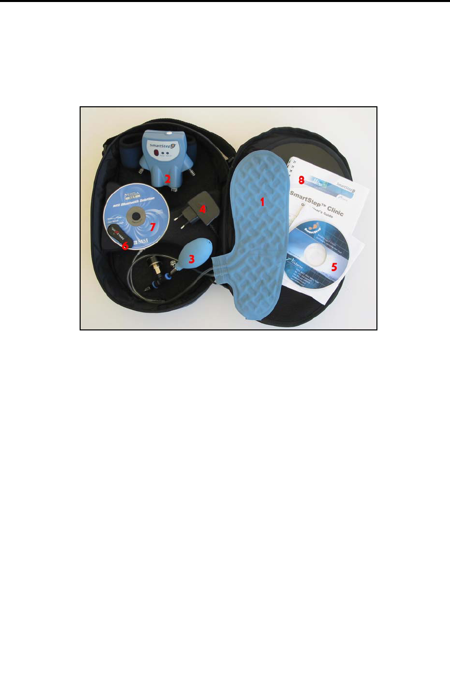
2.1 SmartStep™ Kit Contents
The SmartStep™ Kit
The SmartStep™ kit contains the following items:
1. 3 insoles in: European sizes 37/8, 41/2 and 43/4
or US sizes 6/7, 8.5/10 and 10.5/11.5.
2. Control Unit with strap (which includes a plastic cover for the Charging
connector).
3. Manual pump.
4. Battery charger for the Control Unit
5. SmartStep software CD.
6. Bluetooth USB adapter.
7. Bluetooth USB adaptor driver installation CD.
8. Quick User’s guide.
If any of the above items are missing, or appear damaged, please contact your
supplier.
System Description
SmartStep™ Components
20 | SmartStep™ Version 2.1.1 Revision A2
2.2 SmartStep™ Components
SmartStep™ consists of four main components: An insole, Control Unit, software and
a manual pump. The following sections explain each of these components in more
detail.
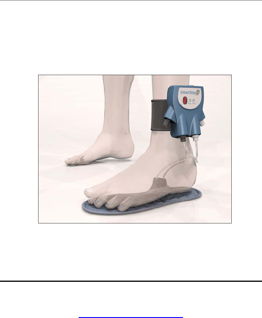
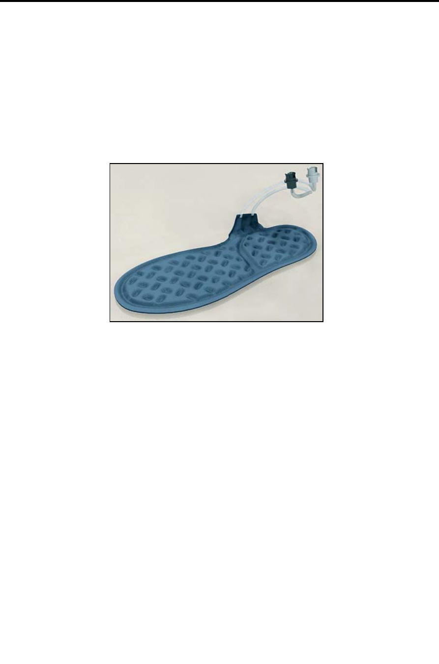
2.2.1 Insole
Insole
The SmartStep™ insole is placed inside the patient’s shoe, and is used to measure
the force exerted by the patient on the foot, during an assessment or a training
session.
The insole contains two inflatable compartments – the forefoot and the hind foot.
Each compartment is connected, via a tube, to a pressure sensor. When a patient
exerts force on the leg, increased air is driven out of the air pockets and is detected
by the pressure sensors and converted into uneven weight in Kg/lb.
SmartStep™ sessions are performed on a single foot at a time. The insole is suitable
for both left and right feet. It is supplied in a range of sizes (see details in 2.1 above).
System Description
Control Unit
SmartStep™ Version 2.1.1 Revision A2 | 21
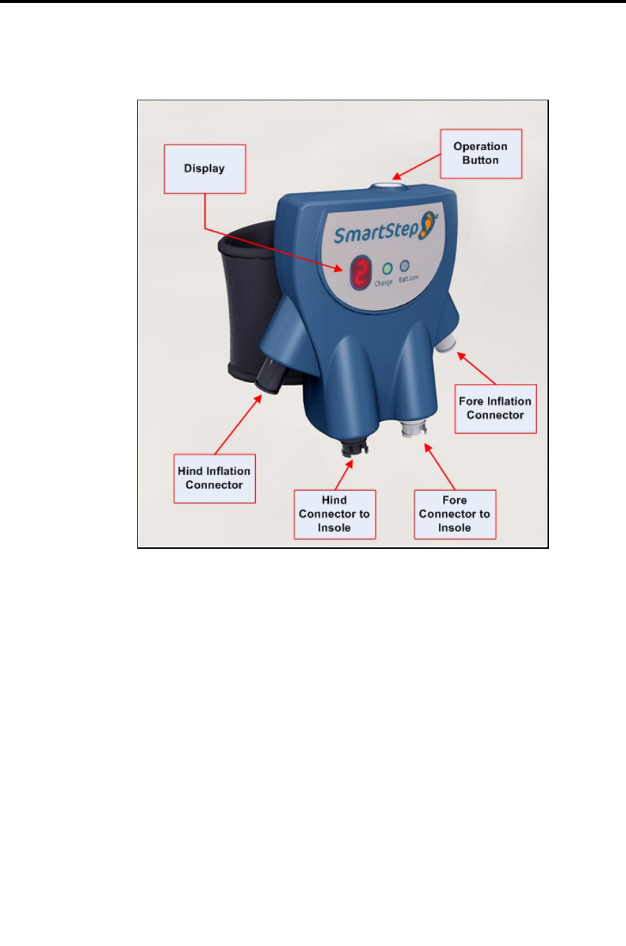
2.2.2 Control Unit
The Control Unit
The SmartStep™ Control Unit serves three purposes:
Data relay to a computer via wireless (Bluetooth) communication. The
computer must have the SmartStep™ software installed (see 3.2). Connecting
the Control Unit to a computer allows you to view a graph of the gait pattern,
as the patient performs an online workout.
Feedback generation when the patient reaches and exceeds the desired
weight range. Audio feedback is optional; it can be turned on and off by
toggling the Control Unit’s operation mode.
Optional data collection in an offline mode that can be turned on or off by
toggling the Control Unit’s operating mode. The collected data can be
downloaded to a computer and view session statistics and graphs.

System Description
Control Unit
22 | SmartStep™ Version 2.1.1 Revision A2
Control Unit Modes of Operation
Operation
mode
Name Description
0 On Control Unit is on.
1 Online
Assessment
Online assessment mode (when no weight thresholds are determined)
with graphic visual feedback of patient performance.
1. Offline
Assessment and
Data collection
Offline assessment mode (when no weight thresholds are determined).
Data is collected. Later it is possible to save it in the patient’s file.
2 Online/Offline
Training
Online/Offline training mode (when weight thresholds are determined).
Audio feedback is available in the form of beeps to alert patient and/or
therapist to weight exerted by the patient. In Online mode graphic
visual feedback is available as well.
2. Offline Training
and Data
collection
Offline training mode (when weight thresholds are determined). Data is
collected. Later it is possible to save it in the patient’s file. Audio
feedback is available in the form of beeps to alert the patient and/or
therapist to weight exerted by the patient.
4 Download
Completed
Data collected offline has successfully been downloaded to the
computer. After a pause, mode reverts to 1 or 2 (without the dot,
depending on the mode before the download process).
4. Download in
Progress
Data collected offline is being downloaded to the computer. When
download is complete, the mode reverts to 4 (without the dot).
E Air Pressure Error Incorrect initial air pressure.
C Wireless Error
Wireless connection was lost.
S Sensor Problem
Sensor error detected.
P Low Air Pressure Air pressure is lost in insole compartments (hind and/or fore).
H Maximum Values
Exceeded
System exceeded maximum values.
L Low Battery
The unit is turned off automatically.
System Description
SmartStep™ Software
SmartStep™ Version 2.1.1 Revision A2 | 23
2.2.3 SmartStep™ Software
The desktop software is used to perform the following functions:
Monitor gait parameters.
Display visual feedback.
Show results and statistics from Online/Offline sessions.
Track rehabilitation progress.
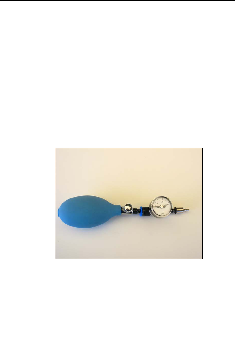
2.2.4 Manual Pump
The Manual Pump
The manual pump is designed to inflate the two compartments with air. The manual
pump is not connected directly to the insole. The inflation is done via the Control Unit.
Installation
System Requirements
24 | SmartStep™ Version 2.1.1 Revision A2
3 Installation
3.1 System Requirements
Microsoft Windows® XP Professional or Home Edition.
128 MB of RAM minimum, 256 MB or greater recommended.
Up to 20 MB of available hard-disk space.
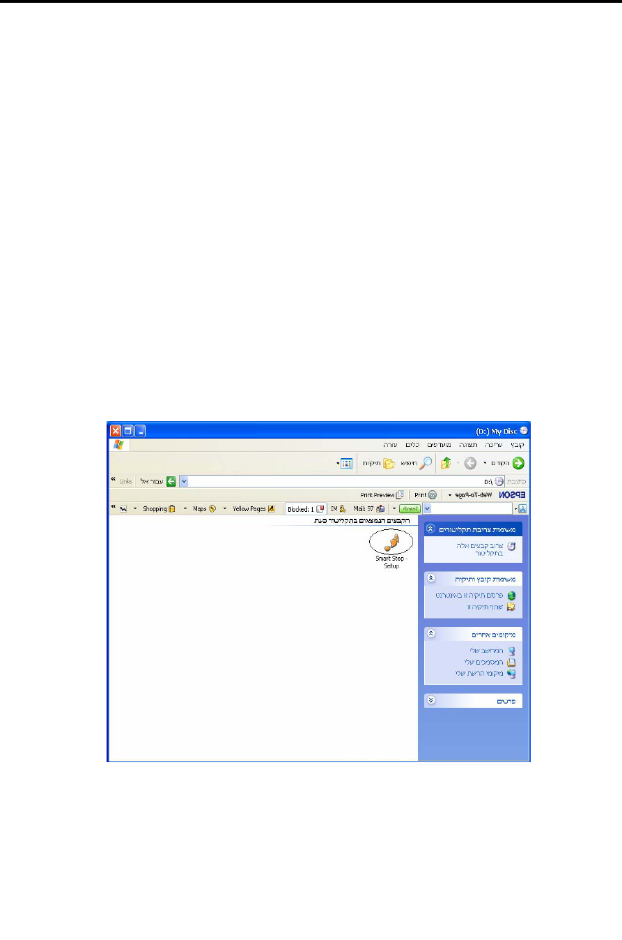
3.2 SmartStep Software Installation
1. Insert the SmartStep Installation disk into the CD-ROM drive.
2. Open the CD-ROM root folder and double click on the SmartStep icon.
Installation
SmartStep Software Installation
SmartStep™ Version 2.1.1 Revision A2 | 25
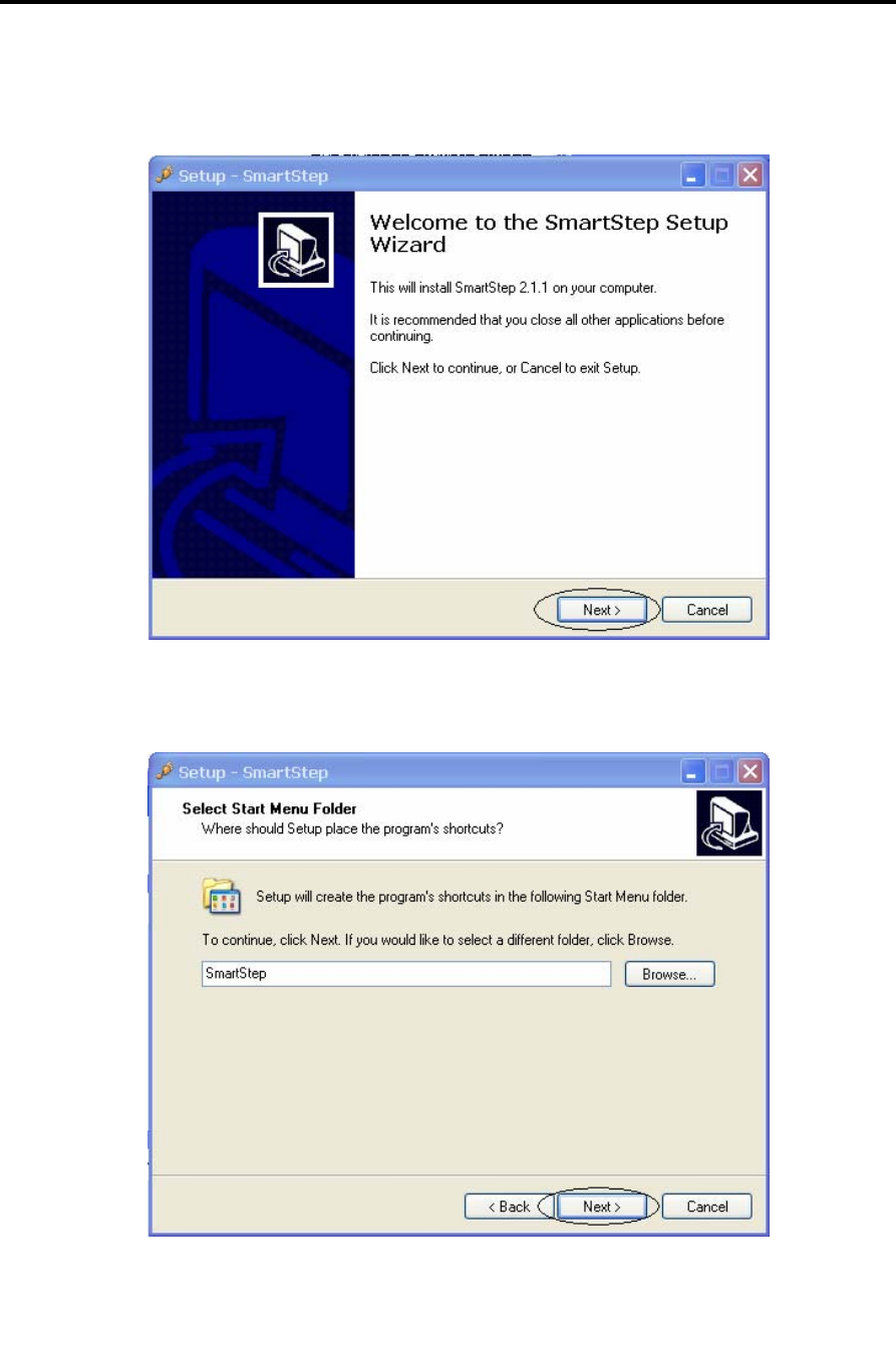
3. Click Next.
4. It is recommended to use the default destination folder. Click Next.
Installation
SmartStep Software Installation
26 | SmartStep™ Version 2.1.1 Revision A2
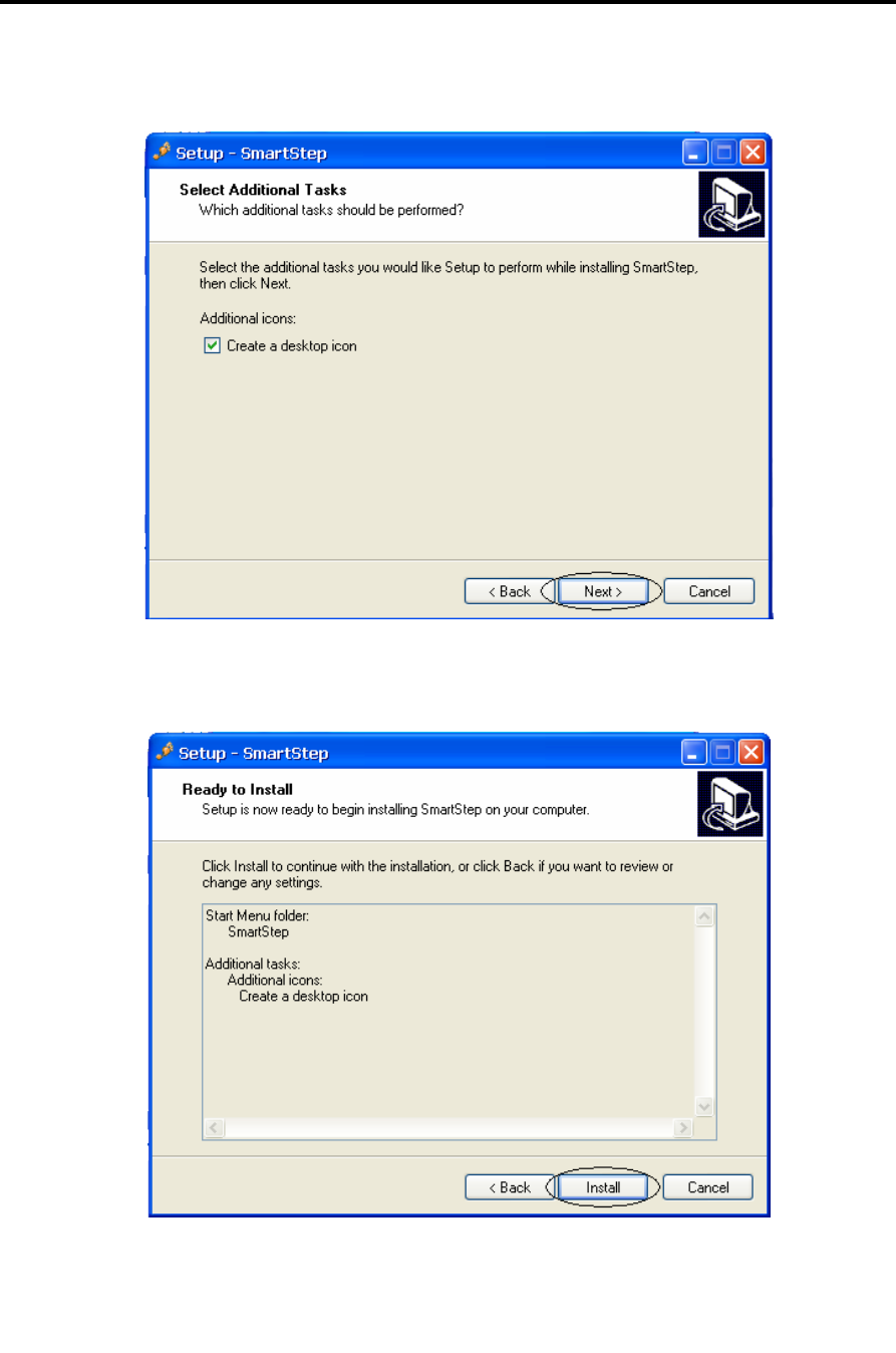
5. It is recommended to check the Create a desktop icon check-box. Click Next.
6. Click Install.
Installation
SmartStep Software Installation
SmartStep™ Version 2.1.1 Revision A2 | 27
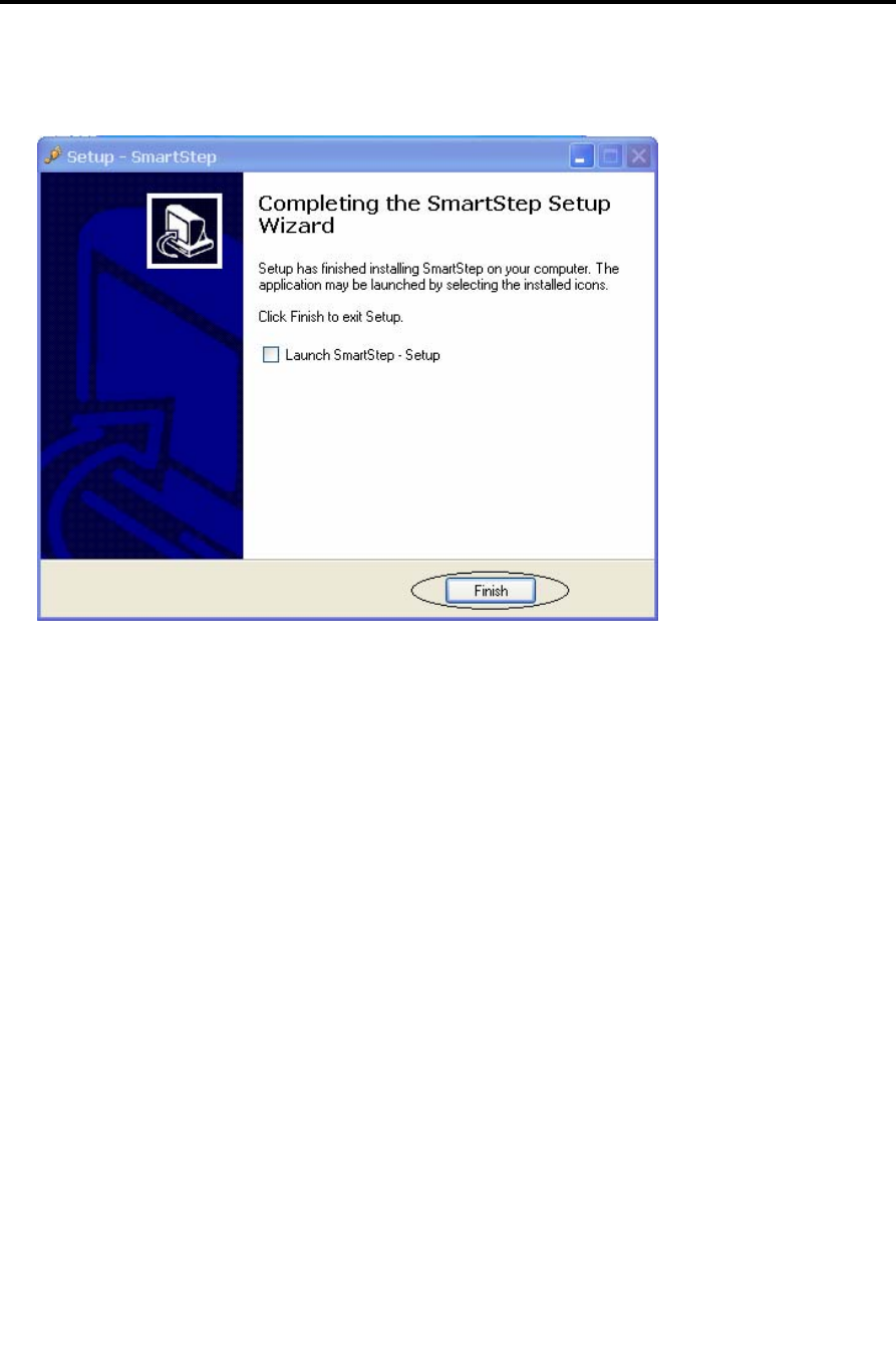
7. Click Finish.
SmartStep installation is now complete. The next step is the Bluetooth USB Adapter
installation.
Installation
Bluetooth USB Adapter Driver Installation
28 | SmartStep™ Version 2.1.1 Revision A2
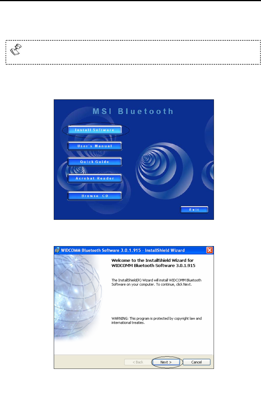
3.3 Bluetooth USB Adapter Driver Installation
To avoid software installation problems, please do NOT insert the Bluetooth
USB Adapter until the installation displays a message to do so (step8).
1. Insert the USB Adapter installation disk into the CD-ROM drive. The Setup
program should launch automatically. Click the Install Software button.
2. Click the Next button.
Installation
Bluetooth USB Adapter Driver Installation
SmartStep™ Version 2.1.1 Revision A2 | 29
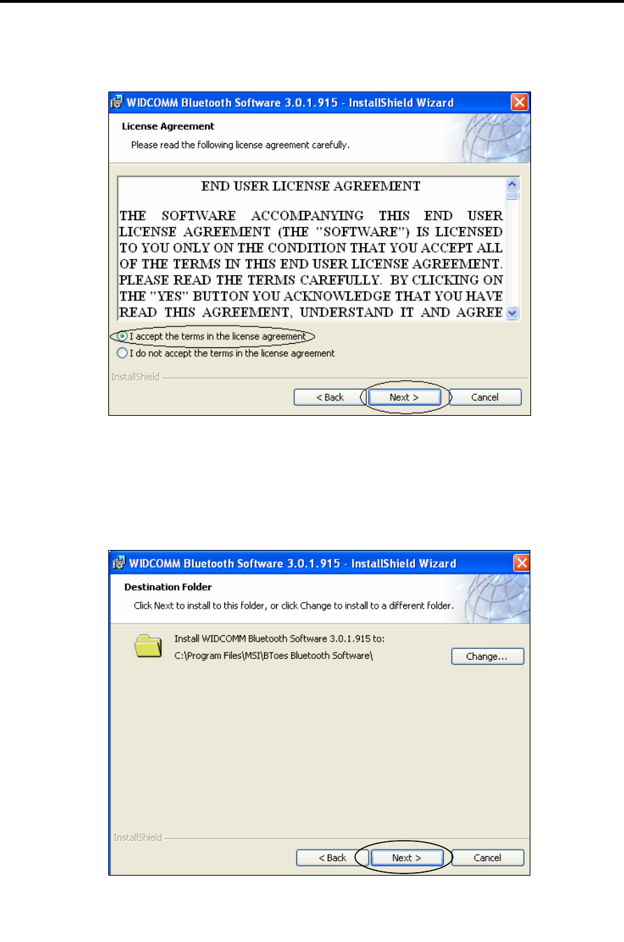
3. Choose the I accept… option, and click the Next button.
4. In this screen it is possible to change the destination folder by clicking the
Change… button. It is recommended to use the default destination folder. Click
Next.
Installation
Bluetooth USB Adapter Driver Installation
30 | SmartStep™ Version 2.1.1 Revision A2
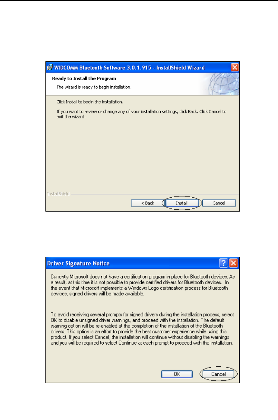
5. Click Install. The installation might take several minutes.
6. If the dialog below opens, click Cancel.
Installation
Bluetooth USB Adapter Driver Installation
SmartStep™ Version 2.1.1 Revision A2 | 31
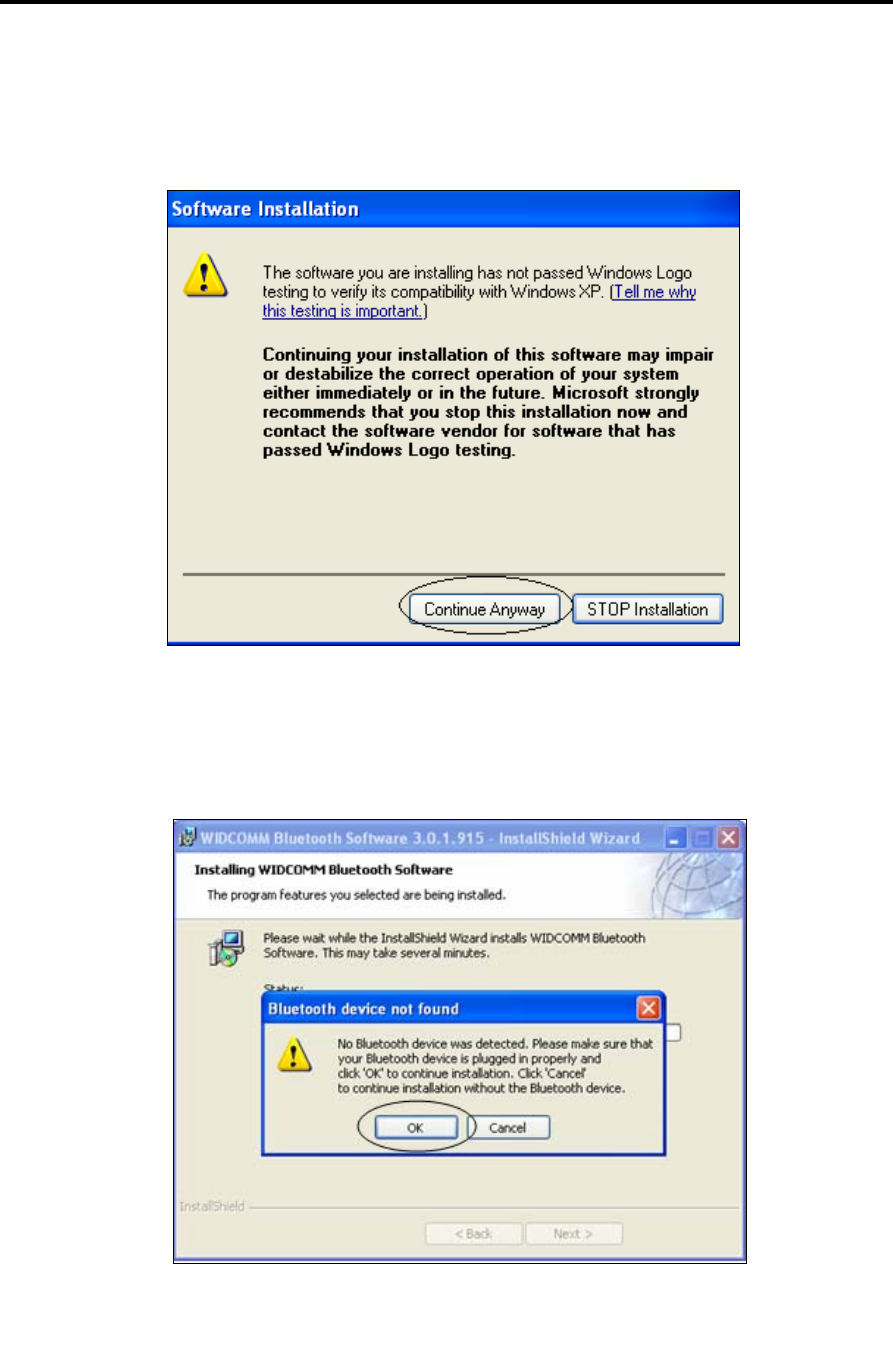
7. If the dialog below opens, click on the Continue Anyway button.
8. A message box indicating that No Bluetooth device was detected should popup.
Please insert the Bluetooth USB adapter and click OK.
Installation
Bluetooth USB Adapter Driver Installation
32 | SmartStep™ Version 2.1.1 Revision A2
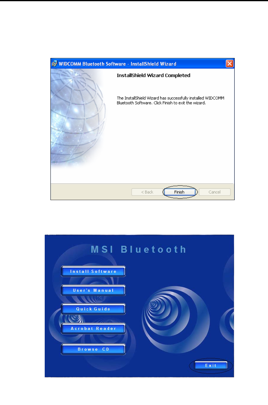
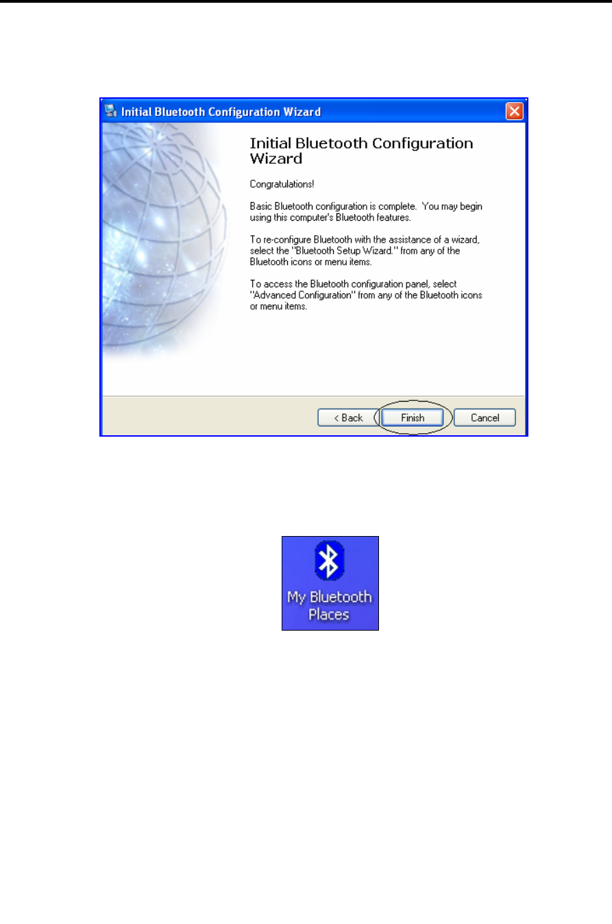
9. Click Finish.
10. Click Exit.
Installation
Bluetooth USB Adapter Driver Installation
SmartStep™ Version 2.1.1 Revision A2 | 33
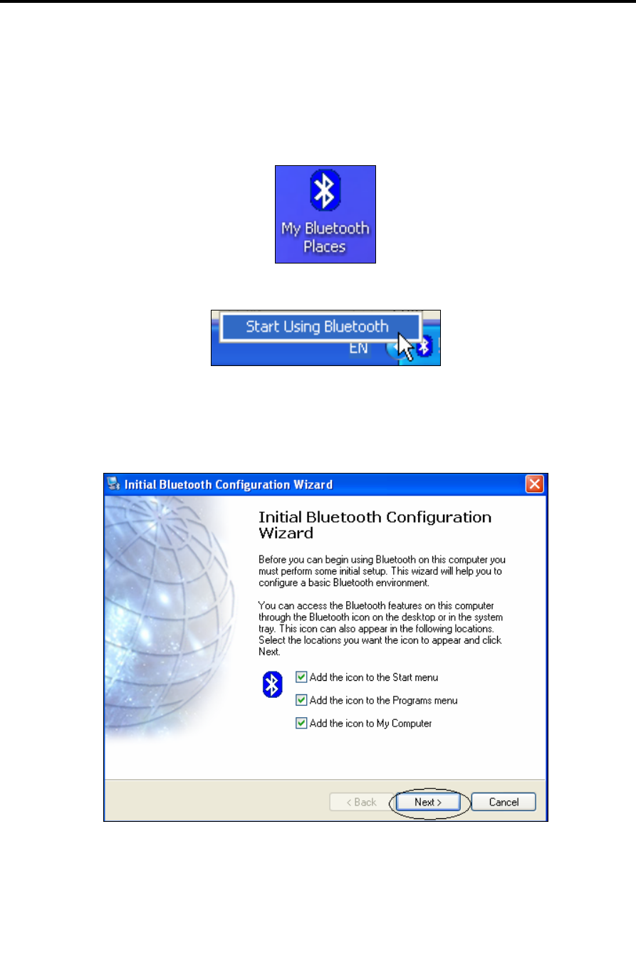
11. Double click on the My Bluetooth Places icon on the desktop. It is also possible to
double click the Bluetooth icon that is located in the notification area of the
taskbar, or to right click it and select Start Using Bluetooth.
12. Click Next.
Installation
Bluetooth USB Adapter Driver Installation
34 | SmartStep™ Version 2.1.1 Revision A2
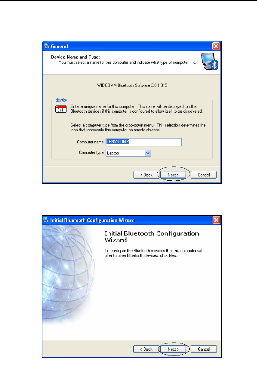
13. Click Next.
14. Click Next.
Installation
Bluetooth USB Adapter Driver Installation
SmartStep™ Version 2.1.1 Revision A2 | 35
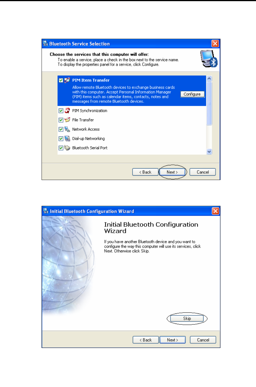
15. Leave the default settings. Click Next.
16. Click Skip.
Installation
Bluetooth USB Adapter Driver Installation
36 | SmartStep™ Version 2.1.1 Revision A2
17. Click Finish.
18. Double click the My Bluetooth Places icon on the desktop.
Installation
Bluetooth USB Adapter Driver Installation
SmartStep™ Version 2.1.1 Revision A2 | 37
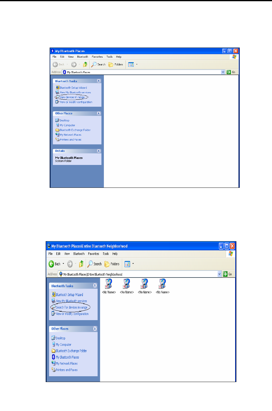
19. Turn the Control Unit on.
In the Bluetooth Tasks menu, click the View Devices in Range option.
20. The list should contain only devices that were already connected to the computer.
In the Bluetooth Tasks menu click the Search for Devices in Range option.
Installation
Bluetooth USB Adapter Driver Installation
38 | SmartStep™ Version 2.1.1 Revision A2
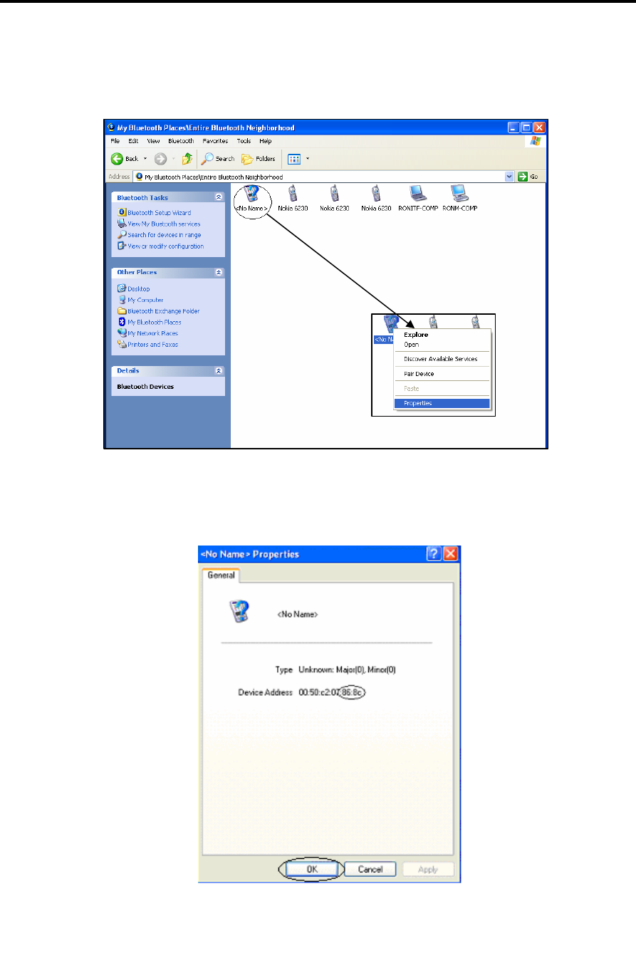
21. Right-click the icon marked with the circle (the icon with the question mark on) .
Choose the Properties option.
22. Make sure that the device address matches the address on the back of the Control
Unit. The 4 characters marked in the screenshot are the Bluetooth Pin Code. Close
the window by clicking OK.
Installation
Bluetooth USB Adapter Driver Installation
SmartStep™ Version 2.1.1 Revision A2 | 39
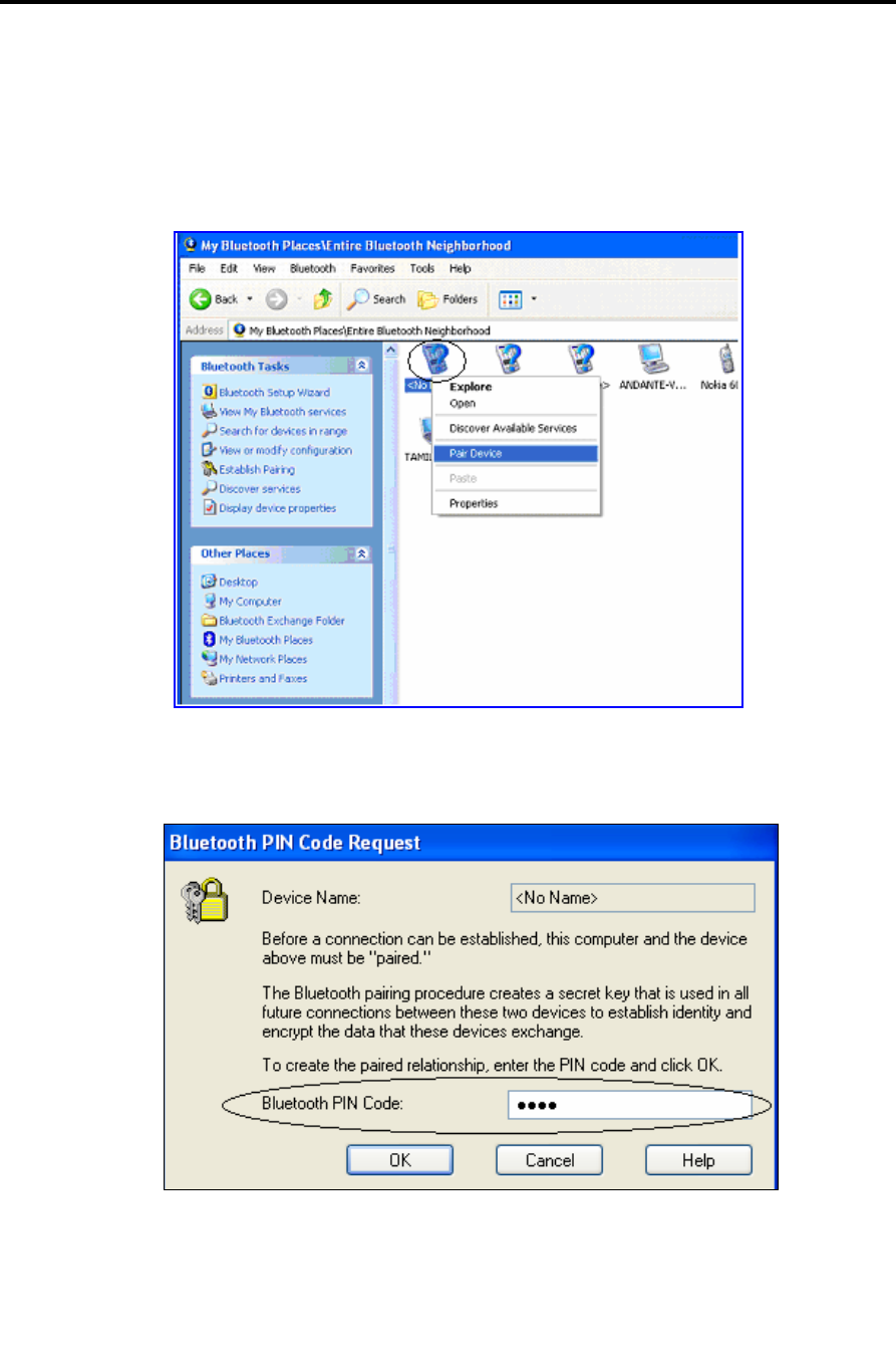
23. Right click the icon marked with the circle (the icon with the question mark on).
Choose the Pair Device option.
24. Enter the four letter Bluetooth Pin Code (marked in the screenshot in step 22).
Use capital letters only. Click OK.
Installation
Bluetooth USB Adapter Driver Installation
40 | SmartStep™ Version 2.1.1 Revision A2
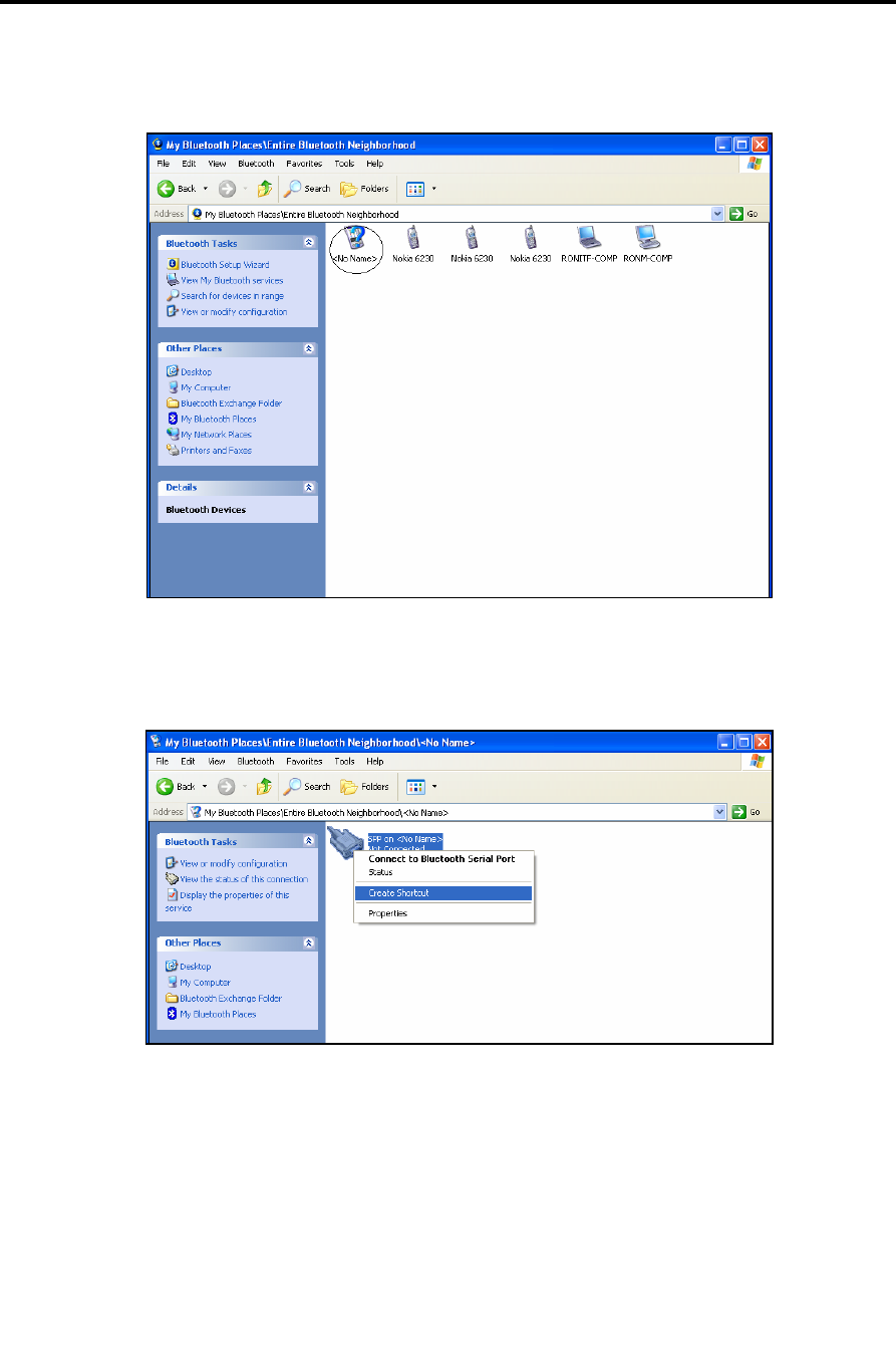
25. Double click the icon marked with a circle (the icon with the question mark on).
26. Right click the icon below and choose the Create Shortcut option.
Installation
Bluetooth USB Adapter Driver Installation
SmartStep™ Version 2.1.1 Revision A2 | 41
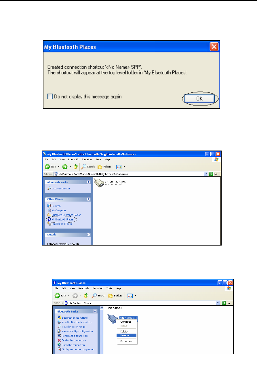
27. Click the OK button.
28. Choose the My Bluetooth Places option, in the Other Places menu.
29. Right-click the marked icon, and Rename it for later easy recognition.
Installation
Bluetooth USB Adapter Driver Installation
42 | SmartStep™ Version 2.1.1 Revision A2
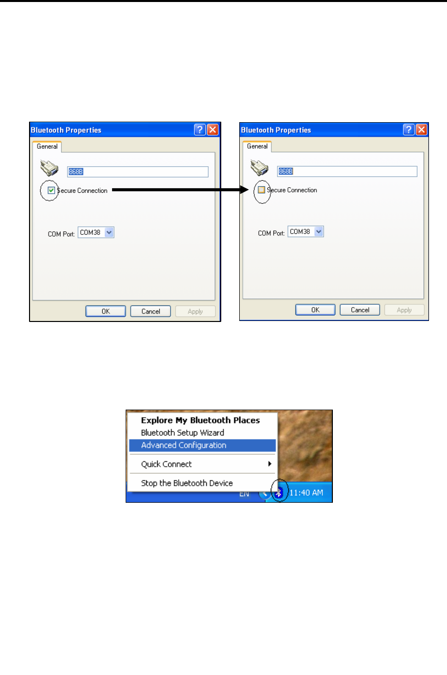
30. Right-click the marked icon again, and choose the Properties option.
31. Uncheck the Secure Connection checkbox. Click OK.
32. In the Taskbar notification area right-click the marked icon. Choose the Advanced
Configuration option.
Installation
Bluetooth USB Adapter Driver Installation
SmartStep™ Version 2.1.1 Revision A2 | 43
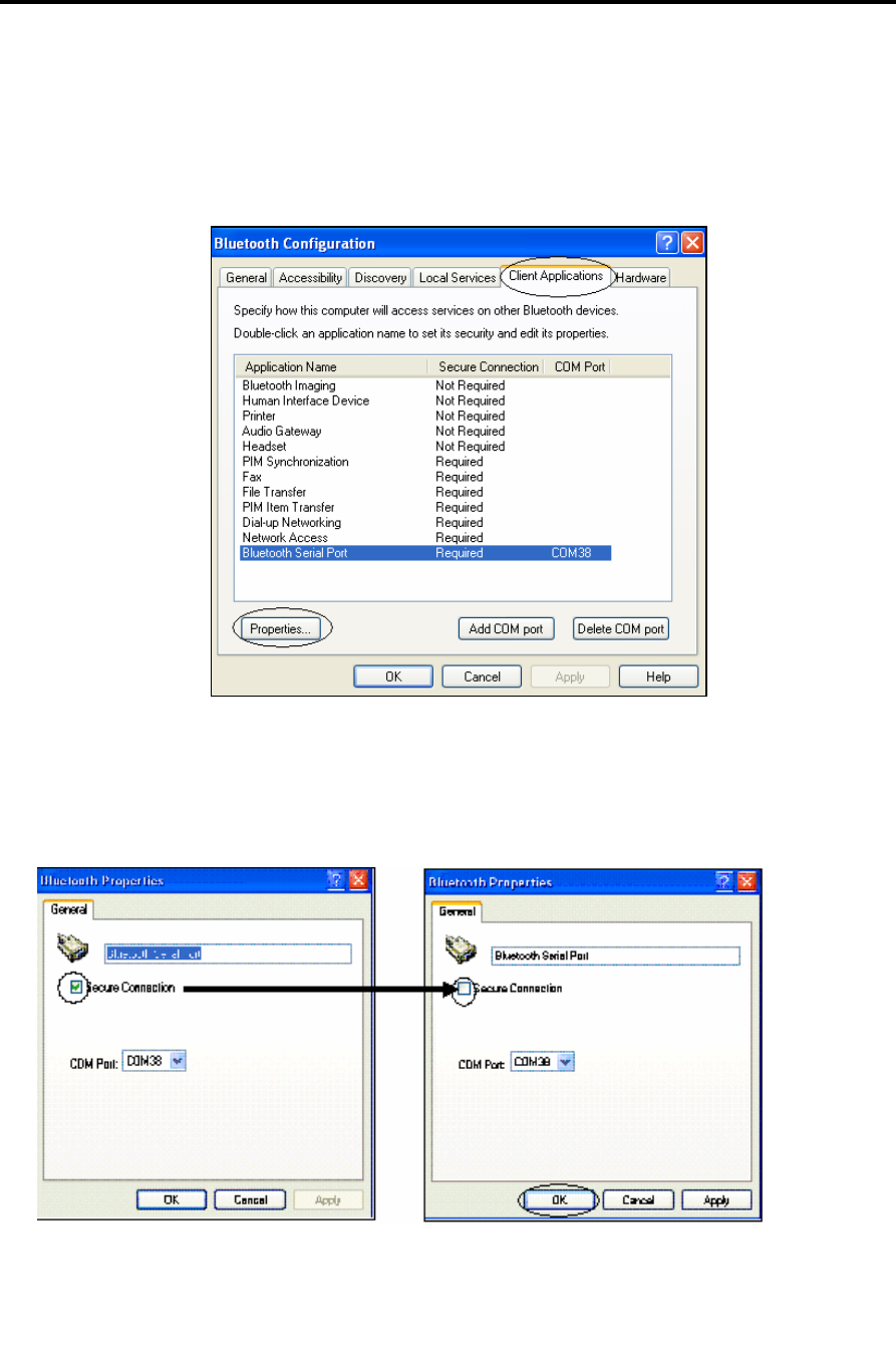
33. Select the Client Applications tab. Select the Bluetooth Serial Port list item
and click the Properties… button.
34. Uncheck the Secure Connection checkbox. Click OK.
Installation
Bluetooth USB Adapter Driver Installation
44 | SmartStep™ Version 2.1.1 Revision A2
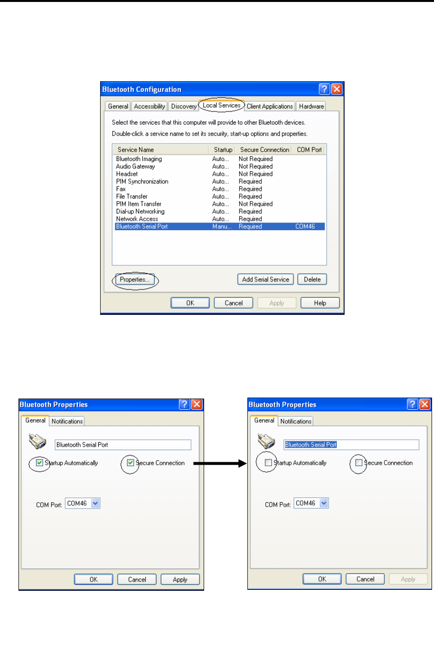
35. Choose the Local Services tab. Select the Bluetooth Serial Port list item and click
the Properties… button.
36. Uncheck the Secure Connection and the Startup Automatically checkboxes. Click OK.
Installation
Bluetooth USB Adapter Driver Installation
SmartStep™ Version 2.1.1 Revision A2 | 45
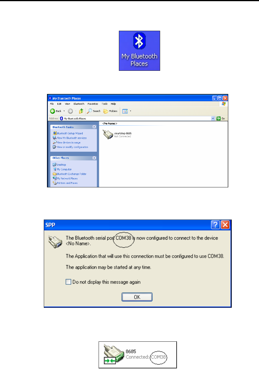
37. Double-click the My Bluetooth Places icon on the desktop.
38. Double-click the icon you named in step 29.
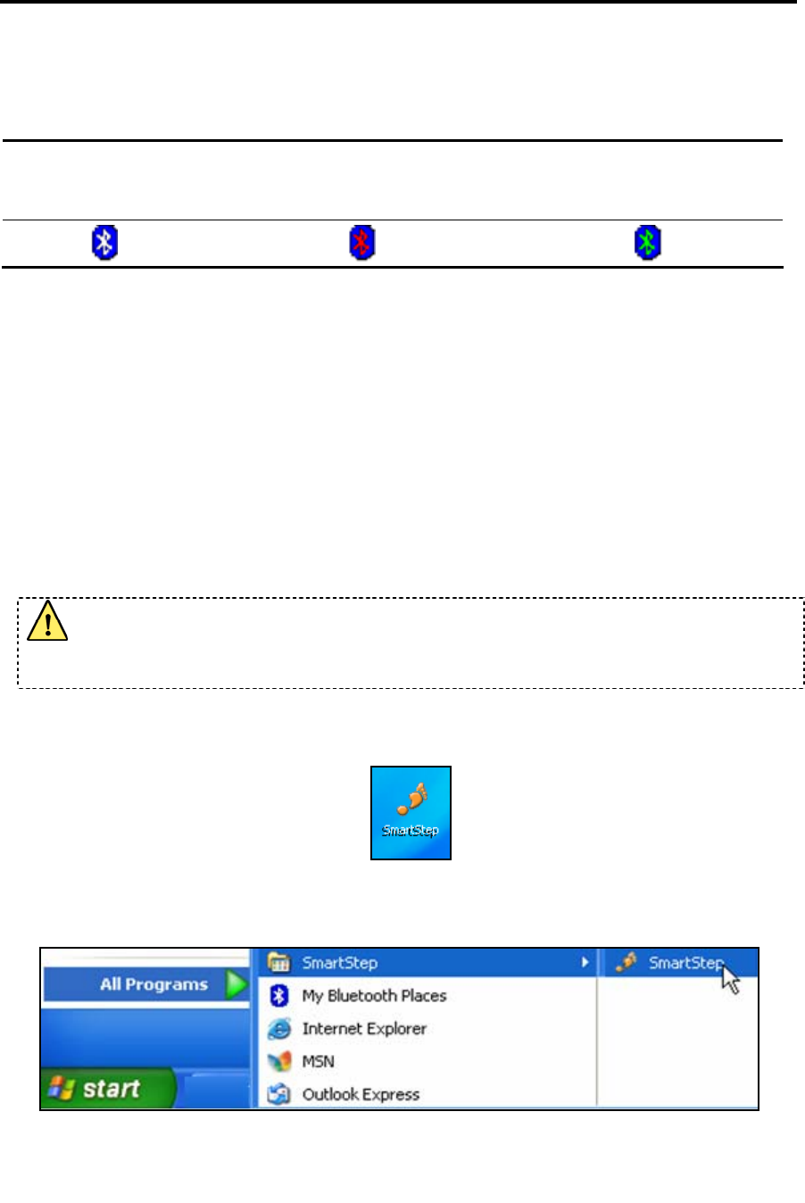
39. The location of the serial port number that is required by the SmartStep program
is marked in the screenshot. Click OK.
40. The icon should change to the icon shown below, the control unit beeps twice to
indicate that the connection with the device has taken place .
Installation
SmartStep™ Antenna Installation Instructions
46 | SmartStep™ Version 2.1.1 Revision A2
The Bluetooth icon that is located in the notification area of the taskbar can be one of the
following colors:
White - The adapter is
connected and enabled.
Red - The adapter is not connected to
the USB port. Bluetooth support is
disabled.
Green - Bluetooth communication
was established.
3.4 SmartStep™ Antenna Installation Instructions
• No antenna installation is needed.
• Antenna is internal and assembly on the PCB (Printed Circuit Board)
3.5 Configure SmartStep™ for Bluetooth Usage
Make sure that the Bluetooth USB adapter is placed at a location free from signal
obstruction. Concrete walls, metal substances, paints with metal composites, etc.
may cause signal obstruction and disable the Bluetooth function.
1. Start the SmartStep™ software, by double-clicking on the desktop shortcut icon
Or by clicking on the SmartStep shortcut in the Start->Program Files->SmartStep
program group.
Installation
Configure SmartStep™ for Bluetooth Usage
SmartStep™ Version 2.1.1 Revision A2 | 47
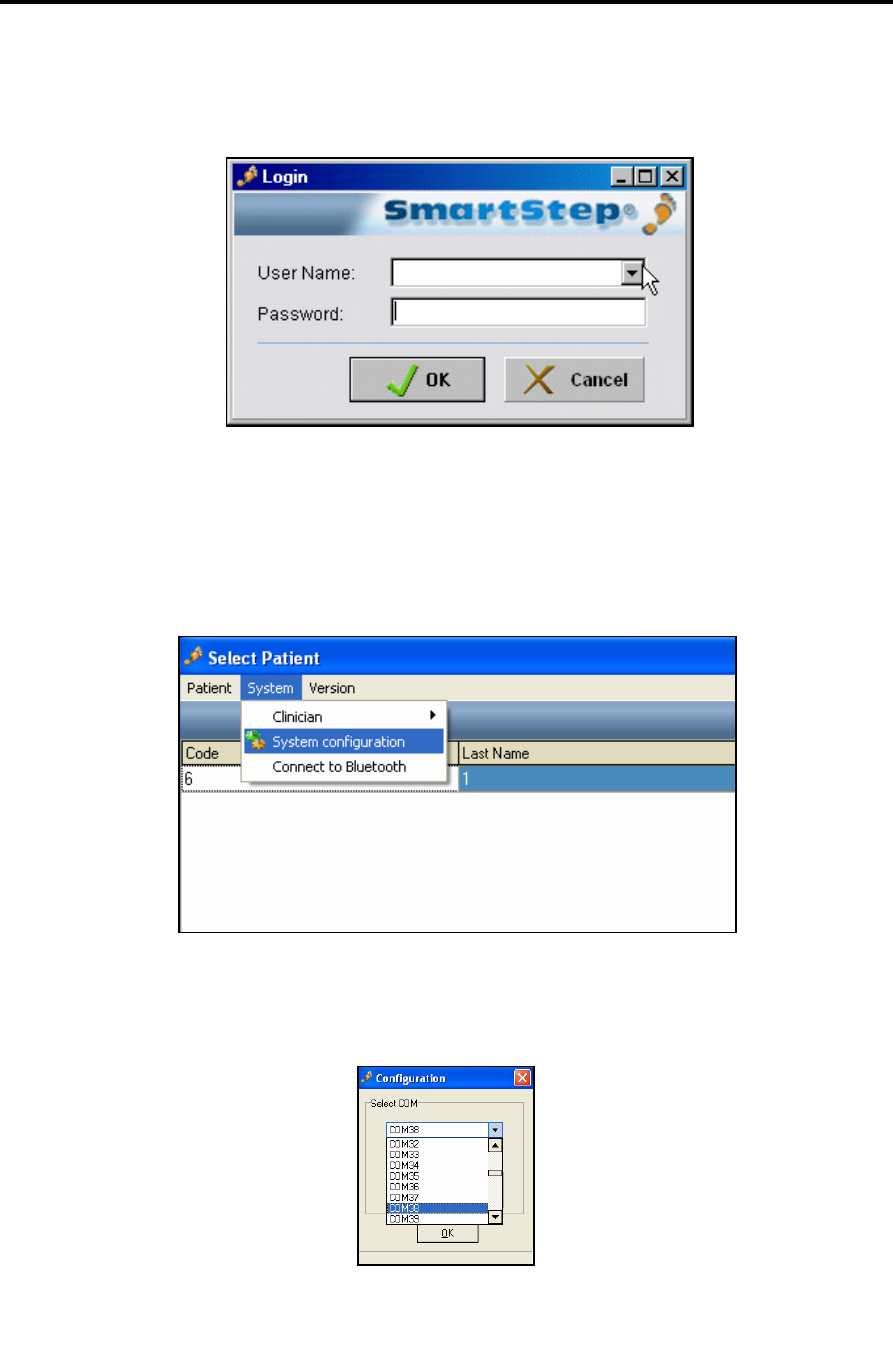
2. The Login dialog box opens.
3. Select your User Name from the drop-down menu and type your Password in the edit
box.
4. Click the OK button to log in.
5. In the Select Patient window, go to the System menu and select System Configuration.
6. In the Configuration window select the correct Bluetooth port number and click OK.
See step 39 of the Bluetooth USB adapter Installation section.