Andrew Base Station Subsystems Group 100252MCPA 45W UMTS 850MHz MCPA RF100252/NTUM30EA User Manual MCPA Users Manual 1 0
Andrew Corporation, Base Station Subsystems Group 45W UMTS 850MHz MCPA RF100252/NTUM30EA MCPA Users Manual 1 0
User Manual

RF Power Amplifiers
Andrew Corporation – Power Amplifier Group
Propriety – Use pursuant to Company Instruction
1 of 6
Multiple Carrier Power Amplifiers
Model: 45W UMTS 850 MHz MCPA
Operation Instruction
Date: January 25, 2007
Version. 1.0
Ref# RE: FCC ID S8L-100252MCPA

RF Power Amplifiers
Andrew Corporation – Power Amplifier Group
Propriety – Use pursuant to Company Instruction
2 of 6
Introduction
This document presents description of the Andrew Corporation 45W UMTS 850MHz
MCPA (Multi-Carrier Power Amplifier). The MCPA amplifier is a high power, low
distortion RF amplifier intended to provide signal amplification and conditioning. The
MCPA amplifier is compatible with the UMTS WCDMA air interfaces operating in U.S.
domestic cell sites where FCC compliance is mandatory.
The 45W UMTS 850MHz MCPA operates in the Cell band (869 MHz to 894 MHz) and
is capable of amplifying up to 2 input signals of the same UMTS WCDMA modulation
types to a composite power level of 45 Watts.
MCPA Specifications
The 45W 850MHz MCPA provides linear amplification of multi-carrier UMTS signals in
the cellular bands. The MCPA has the following specifications:
Parameter Specification
Operating RF Band 869-894 MHz
Instantaneous BW 10 MHz
Input DC Power 357Watts max
DC voltage input range -36 VDC to -60 VDC, -48 VDC, nominal
Rated Output Power
@-48 VDC input 45W average
DC-RF Efficiency 14%, rated output power, nominal input voltage
Input signal types UMTS WCDMA
Physical dimensions 335mm(H)X450mm(W)X400mm(D)
Weight < 23.2 lbs
Cooling technique Integral forced convection heat sink. Need external
fan tray for forced air cooling.
Temperature Range -5°C to +55°C operational and meeting
specifications.
Table 1 MCPA Specifications

RF Power Amplifiers
Andrew Corporation – Power Amplifier Group
Propriety – Use pursuant to Company Instruction
3 of 6
The MCPA amplifier has been designed to support a max instantaneous bandwidth of 10
MHz which is equivalent to the 2 carrier UMTS WCDMA signal. The MCPA amplifier
has a nominal gain of 46.5dB and is less than 1dB variation over the operating
temperatures. The nominal RF input power is 0dBm.
Functional Blocks:
The Andrew MCPA is comprised of the following functional areas:
− Pre-distortion circuit which comprise small signal gain stage, vector modulator and
coaxial delay line
− Main amplifier stage which comprise two high power modules, output isolator and
gain control circuit
− Power conversion and conditioning circuit
− Controller circuit
− Communications circuit
Inputs and Outputs:
The amplifier is powered from a DC supply voltage, which can range from -36V to -60V.
The DC power is brought into the amplifier through a 3 pins D-Sub connector located on
the front panel of the amplifier. A switch also located on the front panel is to turn on/off
the DC power of amplifier.
A 25-pin D-Sub connector located on the amplifier front panel is used for RS-485
communication. Alarms and operating state are communicated to the outside world
through the RS-485 communications bus, and visible bi-color LED located on the
amplifier front panel.
The RF signal is brought into the amplifier through a pair of female SMA type
connectors located on the front panel of the amplifier. The RF1 input connector is used
by default and the RF2 input is for backup. The amplifier RF signal is brought out of the
amplifier through an N type connector located on the front panel of the amplifier.
RF Power Amplifiers
Andrew Corporation – Power Amplifier Group
Propriety – Use pursuant to Company Instruction
4 of 6
Control System:
The MCPA will work with the customer BTS which control and monitor the MCPA by
the specified interface protocol.
A microprocessor controller is inside the MCPA to be compatible with the customer
interface protocol and assures the MCPA performance meet the specification. The micro-
processor controller is used to enable the PA to start/stop working, control the amplifier
alarm system, control environmental compensation of the amplifier, and to maintain a
linearization solution for the pre-distortion circuit.
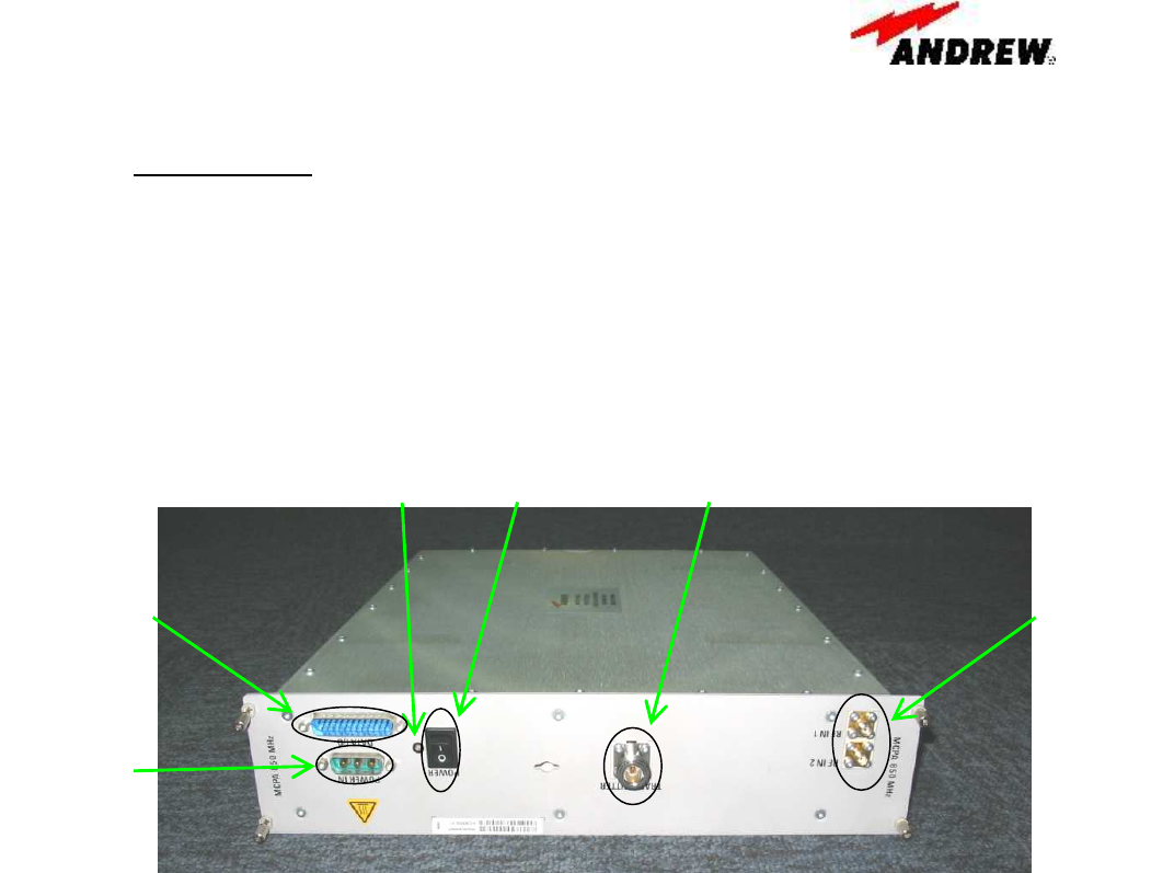
Figure 1 45W UMTS 850MHz MCPA Front Panel
The following table is a summary of detailed alarms within the PA Module. The alarms
are mapped to front panel bi-color LED behavior, as indicated. Additionally, the alarms
messages are sent to the BTS by the RS-485 communication bus.
Bi-color
LED DC power
Switch
RS-485
communication
connector
DC power
connector
RF output
connector
RF input
connector

RF Power Amplifiers
Andrew Corporation – Power Amplifier Group
Propriety – Use pursuant to Company Instruction
5 of 6
Condition Alarm Type LED color
Comments
Initial Power On (RF disabled),
no alarms - Red Wait for RF enable command
Normal Operation – RF enabled - Green -
High temp, Major Red Happen when the MCPA internal detected temperature is
higher than 90C.
The MCPA will shut down
DC power consumption
overload Major Red Happen when the DC consumption Power exceed the
maximum available DC power.
The MCPA will shut down
RF overdrive Minor Red Happen when the RF input power is 6dB higher than the
nominal value.
The MCPA will Shut down
Linearizer Minor Red
Happen when the MCPA linearity performance worsens
than the pre-defined threshold and the condition last
more than 30 seconds.
The MCPA will shut down
Device health and Internal
Voltages out of range Minor Red This alarms include many scenarios, but all related with
the device performance degradation So it’s always others
alarms accompany with this alarms
Gain out of range Minor Red Gain is not in the specified range even with the gain
compensation.
The MCPA will Shut down
DC-DC Converter shut down Major Red The MCPA will Shut down
Table 2 Alarm mapping for PA Module

RF Power Amplifiers
Andrew Corporation – Power Amplifier Group
Propriety – Use pursuant to Company Instruction 6 of 6
Installation and Operation Set-Up
The MCPA is easy to operate and use. All the require connections is located on the front
panel of the MCPA where is easy to access. The MCPA will be installed on slide-in rack
first. Make sure the DC power switch is in the OFF position, and then connect the DC
power, the communication and the RF input/output cable to the MCPA. After check the
all connection is correct and reliable, the last step is to turn on the DC power switch.
FCC Statements:
FCC ID S8L-100252MCPA
This devise complies with Part 2, 15 & 22 of the FCC Rules. Operation is subject to the
following two conditions: (1) this device may not cause harmful interference and (2) this
device must accept any interference received, including interference that may cause
undesired operation.
Warning
Changes of modifications not expressly approved by the manufacturer could void the
user’s authority to operate the equipments.