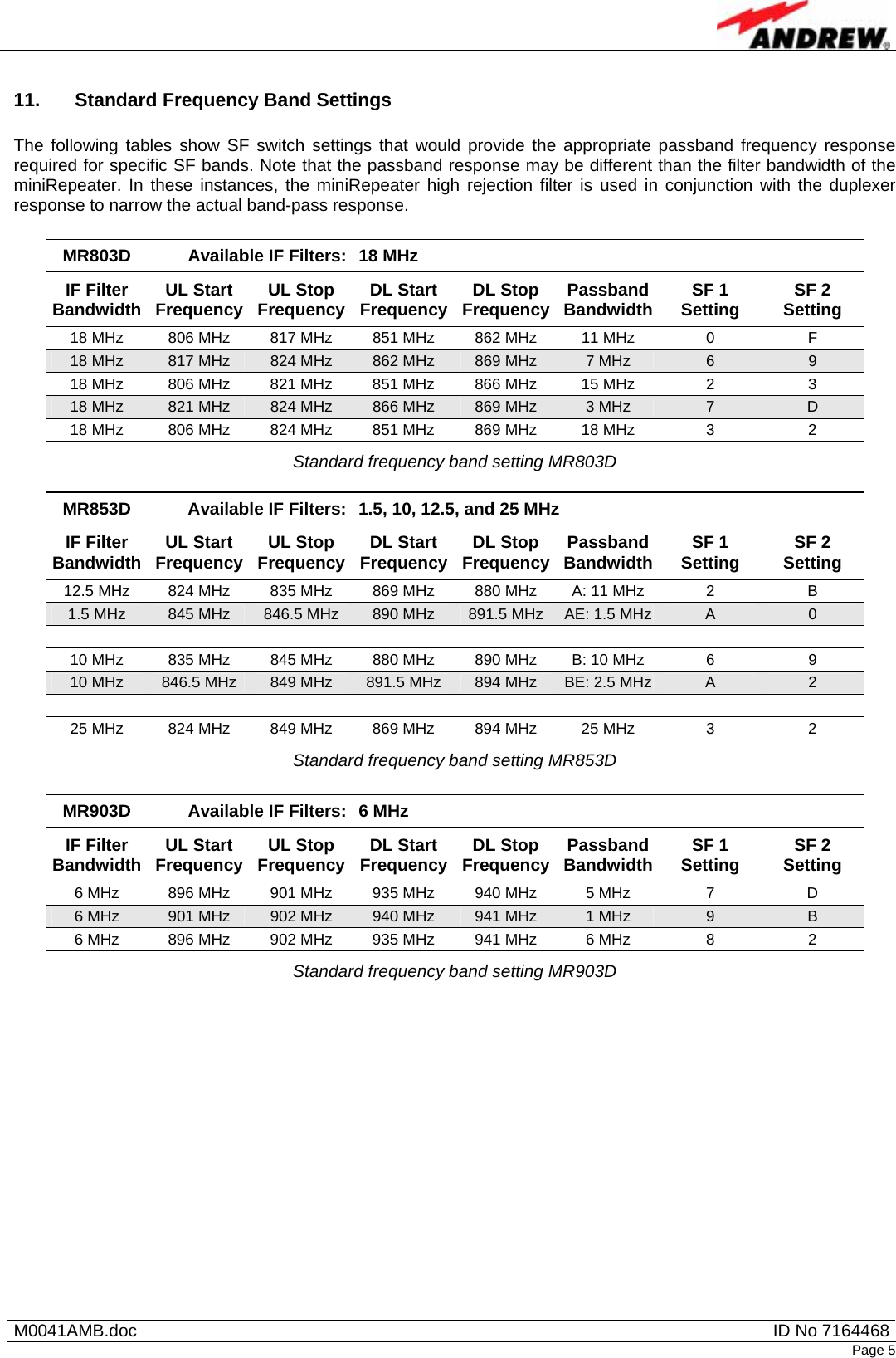
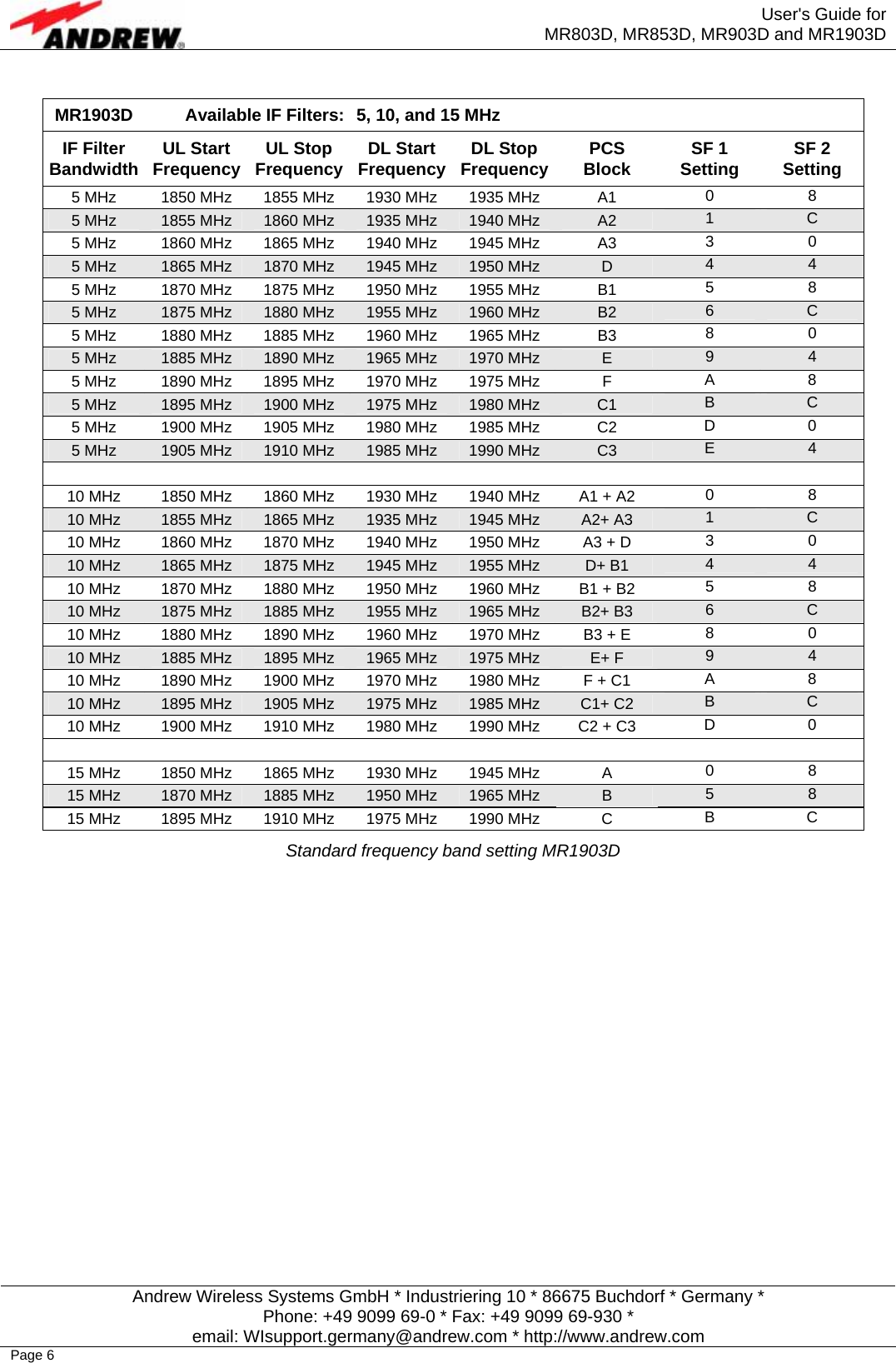
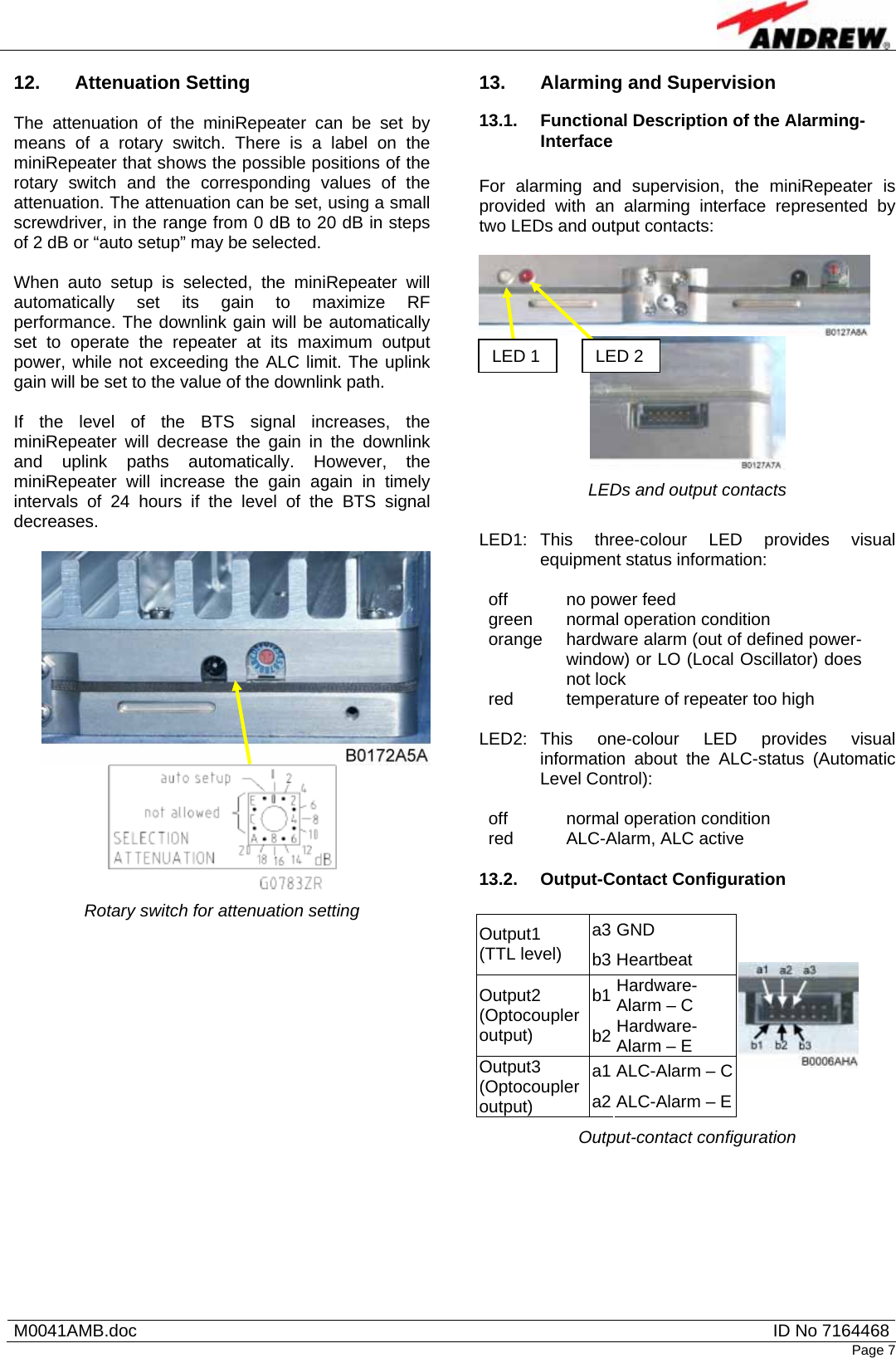
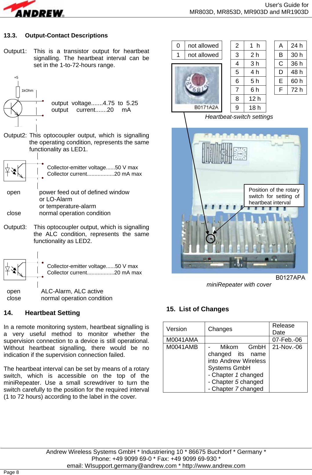
Andrew Wireless Innovations Group 803D15 Transmitter Non-Broadcast Booster User Manual User s Guide for MR803D MR853D MR903D MR1903D

Andrew Wireless Innovations Group Transmitter Non-Broadcast Booster User s Guide for MR803D MR853D MR903D MR1903D

Manual

   M0041AMB.doc  ID No 7164468Page 1 User's Guide for MR803D, MR853D, MR903D and MR1903D miniRepeaters  TABLE OF CONTENTS  1. Safety and Environmental................................... 1 2. Quick-Start Checklist........................................... 1 3. RF and Power Connectors.................................. 1 4. Functional Description........................................ 2 5. Cabinet Drawing................................................... 2 6. Wall Mounting....................................................... 2 7. Mechanical Specification .................................... 2 8. Environmental and Safety Specifications ......... 2 9. 20 dB Bandwidth.................................................. 2 10. Start-Frequency Switch Settings ....................... 3 11. Standard Frequency Band Settings................... 5 12. Attenuation Setting.............................................. 7 13. Alarming and Supervision .................................. 7 13.1. Functional Description of the Alarming-Interface  7 13.2. Output-Contact Configuration  7 13.3. Output-Contact Descriptions  8 14. Heartbeat Setting ................................................. 8 15. List of Changes.................................................... 8  1.  Safety and Environmental  The electrical installation has to be performed in accordance with the safety regulations of the local authorities. Due to safety reasons, the electrical installation must be performed by qualified personnel only. The repeater must not be opened. The antennas of the repeater (integrated and / or external) have to be installed in a way that the regional and national RF exposure compliance requirements are met. To comply with FCC RF exposure compliance requirements, the following antenna installation and device operating configurations must be satisfied: A separation distance of at least 20 cm must be maintained between the antenna of this device and all persons. RF exposure compliance may need to be addressed at the time of licensing, as required by the responsible FCC Bureau(s), including antenna co-location requirements of 1.1307(b)(3). Maximum permissible antenna gain is 12 dBi.  The miniRepeaters must only be used for indoor applications!   2. Quick-Start Checklist   Adjust channel(s); see chapter 10.  Mount the repeater; see chapter 6.  Install donor and coverage antennas.  Provide the repeater with power; see chapter 3.  Adjust the attenuation; see chapter 12.  Start the adjustment with the maximum attenuation and decrease attenuation until the ALC becomes active and the ALC alarm LED lights up. Then increase attenuation until the ALC alarm is inactive again. or  Select auto-setup; see chapter 12.  Check for alarms; see chapter 13.  3.  RF and Power Connectors  G0783ZR   The miniRepeaters are equipped with two RF antenna ports: one antenna port that provides RF signals to/from mobile(s) and another antenna port on the opposite side of the miniRepeater that provides RF signals side to/from the BTS. Both of these connectors are SMA-Female. Two coaxial jumper cables are included with the miniRepeaters to provide N-female connection ports.  The socket for the DC supply is situated to the right of the “to/from BTS” RF connector. The power supply voltage for this connection point is 6.7 to 7.5 VDC, with a typical current draw of 1.7 amps. Only the Power Supply Unit (PSU) supplied with the MiniRepeater must be used.  An alternative method to provide power to the MiniRepeater is through the “to/from BTS” RF connector via the coaxial cable and a bias-T at the source. The DC socket of the repeater must not be connected if the unit is biased via the RF port.
 User's Guide for MR803D, MR853D, MR903D and MR1903D  Andrew Wireless Systems GmbH * Industriering 10 * 86675 Buchdorf * Germany * Phone: +49 9099 69-0 * Fax: +49 9099 69-930 * email: WIsupport.germany@andrew.com * http://www.andrew.com Page 2 4. Functional Description  The operation principle of the miniRepeaters is given with regard to the following block diagram.  manual AttenuationsettingautomaticE0783B0   Downlink signals from the BTS reach the internal duplexer through the “to/from BTS” RF port. Following the DL path from the duplexer, the RF signals are amplified by an LNA, which feeds the amplified signals to a mixer. The mixer converts the signals down to an intermediate frequency (IF), where a high rejection IF filter provides excellent selectivity to allow only the user’s frequency band to be repeated. After the IF filter, the signals are re-converted to the original frequency by means of another mixer. A final amplifier boosts the RF signals to the required output power.  After the final amplifier, a power detection circuit measures the output power and controls the gain through a closed loop feedback circuit. This feature is the automatic level control (ALC), which prevents the repeater from being overdriven and maintains intermodulation products and spectrum emissions below the regulation limits. Finally, the RF signals are fed to the external antenna through the duplexer and “to/from Mobile” RF port.  The uplink signals are received by the external antenna through the “to/from Mobile” RF port and are then fed to the duplexer. After the duplexer the RF circuitry and functionality is identical to the downlink path, which provides high rejection filtering for the desired operation frequency band and ALC functionality.  5. Cabinet Drawing  G0825Z8   6. Wall Mounting   The miniRepeater may only be mounted horizontally to a wall according to the above drawing to ensure the natural convection cooling. Do not mount the miniRepeater to the ceiling!   Always choose a mounting location that avoids condensation!  7. Mechanical Specification  Size H x W x D  114 x 154 x 51.5 mm (4.5 x 6.1 x 2.0 inch) Weight 0.7 kg Sealing Class  IP30  8.  Environmental and Safety Specifications  The environmental specifications are according to ETS 300 019 (European Telecommunication Standard) and the safety specifications are according to UL Std No 1950 and CAN/CSA-C22.2 No. 60950. For further details please ask your supplier.  9.  20 dB Bandwidth  MR803D, 18 MHz Filter  18.7 MHz  MR853D, 1.5 MHz Filter  2.1 MHz MR853D, 10 MHz Filter  10.7 MHz MR853D, 12.5 MHz Filter  13.2 MHz MR853D, 25 MHz Filter  24.7 MHz  MR903D, 6 MHz Filter  6.6 MHz  MR1903D, 5 MHz Filter  7.0 MHz MR1903D, 10 MHz Filter  11.0 MHz MR1903D, 15 MHz Filter  16.0 MHz 20 dB bandwidth Wall Mounting bracket miniRepeater V1550_X03
  M0041AMB.doc  ID No 7164468Page 3 10.  Start-Frequency Switch Settings  As described in chapter 4 Functional Description, the miniRepeaters utilise a high rejection filter to allow only the desired frequency band to be repeated. The miniRepeaters are available in different bandwidths with field adjustable start frequencies to support the desired frequency band of the user.   Two rotary switches, located on the side of the miniRepeater, are provided for setting the start frequency (SF) of the high rejection filter. The SF of the high rejection filter may be adjusted in either 200 or 250 kHz steps, dependent upon the miniRepeater model. Following are tables that show the filter band-pass start frequencies corresponding to the switch settings. The following section will show tables of standard user settings.   Rotary switches for start-frequency setting  miniRepeater Model: MR803D  Frequency Step Size:  200 kHz Start Frequency Setting 1  Start Frequency Setting 2  Start FrequencyUL (MHz)  Start Frequency DL (MHz) 0 0 796.00 841.00 0 1 796.20 841.20 0 2 796.40 841.40 …  … … … 0  F  799.00 844.00 1 0 799.20 844.20 1 1 799.40 844.40 …  …  … … 1  F  802.20 847.20 … … … … F  0 844.00 889.00 F  1 844.20 889.20 …  … … … F F 847.00 892.00 Start-frequency setting MR803D  miniRepeater Model: MR853D  Frequency Step Size:  200 kHz Start Frequency Setting 1  Start Frequency Setting 2  Start FrequencyUL (MHz)  Start Frequency DL (MHz) 0 0 814.00 859.00 0 1 814.20 859.20 0 2 814.40 859.40 …  … … … 0  F  817.00 862.00 1 0 817.20 862.20 1 1 817.40 862.40 …  … … … 1  F  820.20 865.20 …  … … … F  0 862.00 907.00 F  1 862.20 907.20 … … … … F F 865.00 910.00 Start-frequency setting MR853D SF setting 1 (positions 0 - F)SF setting 2 (positions 0 - F)
 User's Guide for MR803D, MR853D, MR903D and MR1903D  Andrew Wireless Systems GmbH * Industriering 10 * 86675 Buchdorf * Germany * Phone: +49 9099 69-0 * Fax: +49 9099 69-930 * email: WIsupport.germany@andrew.com * http://www.andrew.com Page 4  miniRepeater Model: MR903D  Frequency Step Size:  200 kHz Start Frequency Setting 1  Start Frequency Setting 2  Start FrequencyUL (MHz)  Start Frequency DL (MHz) 0 0 870.00 909.00 0 1 870.20 909.20 0 2 870.40 909.40 …  … … … 0  F  873.00 912.00 1 0 873.20 912.20 1 1 873.40 912.40 …  … … … 1  F  876.20 915.20 …  …  … … F  0 918.00 957.00  F  1 918.20 957.20 …  … … …  F  F  921.00 960.00 Start-frequency setting MR903D  miniRepeater Model: MR1903D  Frequency Step Size: 250 kHz Start Frequency Setting 1 Start Frequency Setting 2 Start Frequency UL (MHz) Start Frequency DL (MHz) 0 0 1848.00 1928.00 0 1 1848.25 1928.25 0 2 1848.50 1928.50 … … … … 0  F  1851.75 1931.75 1 0 1852.00 1932.00 1 1 1852.25 1932.25 … … … … 1  F  1855.75 1935.75 …  … … … F  0 1908.00 1988.00 F  1 1908.25 1988.25 …  … … … F F 1911.75 1991.75 Start-frequency setting MR1903D
  M0041AMB.doc  ID No 7164468Page 5 11.  Standard Frequency Band Settings  The following tables show SF switch settings that would provide the appropriate passband frequency response required for specific SF bands. Note that the passband response may be different than the filter bandwidth of the miniRepeater. In these instances, the miniRepeater high rejection filter is used in conjunction with the duplexer response to narrow the actual band-pass response.  MR803D  Available IF Filters:  18 MHz IF Filter Bandwidth  UL Start Frequency UL Stop Frequency  DL Start Frequency DL Stop Frequency Passband Bandwidth SF 1 Setting  SF 2 Setting 18 MHz  806 MHz  817 MHz  851 MHz  862 MHz  11 MHz  0  F 18 MHz  817 MHz  824 MHz  862 MHz  869 MHz  7 MHz  6  9 18 MHz  806 MHz  821 MHz  851 MHz  866 MHz  15 MHz  2  3 18 MHz  821 MHz  824 MHz  866 MHz  869 MHz  3 MHz  7  D 18 MHz  806 MHz  824 MHz  851 MHz  869 MHz  18 MHz  3  2 Standard frequency band setting MR803D  MR853D  Available IF Filters:  1.5, 10, 12.5, and 25 MHz IF Filter Bandwidth  UL Start Frequency UL Stop Frequency  DL Start Frequency DL Stop Frequency Passband Bandwidth SF 1 Setting  SF 2 Setting 12.5 MHz  824 MHz  835 MHz  869 MHz  880 MHz  A: 11 MHz  2  B 1.5 MHz  845 MHz  846.5 MHz  890 MHz  891.5 MHz  AE: 1.5 MHz A  0         10 MHz  835 MHz  845 MHz  880 MHz  890 MHz  B: 10 MHz  6  9 10 MHz  846.5 MHz  849 MHz  891.5 MHz  894 MHz  BE: 2.5 MHz A  2         25 MHz  824 MHz  849 MHz  869 MHz  894 MHz  25 MHz  3  2 Standard frequency band setting MR853D  MR903D  Available IF Filters:  6 MHz IF Filter Bandwidth  UL Start Frequency UL Stop Frequency  DL Start Frequency DL Stop Frequency Passband Bandwidth SF 1 Setting  SF 2 Setting 6 MHz  896 MHz  901 MHz  935 MHz  940 MHz  5 MHz  7  D 6 MHz  901 MHz  902 MHz  940 MHz  941 MHz  1 MHz  9  B 6 MHz  896 MHz  902 MHz  935 MHz  941 MHz  6 MHz  8  2 Standard frequency band setting MR903D
 User's Guide for MR803D, MR853D, MR903D and MR1903D  Andrew Wireless Systems GmbH * Industriering 10 * 86675 Buchdorf * Germany * Phone: +49 9099 69-0 * Fax: +49 9099 69-930 * email: WIsupport.germany@andrew.com * http://www.andrew.com Page 6  MR1903D  Available IF Filters:  5, 10, and 15 MHz IF Filter Bandwidth  UL Start Frequency UL Stop Frequency  DL Start Frequency DL Stop Frequency PCS Block  SF 1 Setting  SF 2 Setting 5 MHz  1850 MHz  1855 MHz  1930 MHz  1935 MHz  A1  0 8 5 MHz  1855 MHz  1860 MHz  1935 MHz  1940 MHz  A2  1  C 5 MHz  1860 MHz  1865 MHz  1940 MHz  1945 MHz  A3  3 0 5 MHz  1865 MHz  1870 MHz  1945 MHz  1950 MHz  D  4  4 5 MHz  1870 MHz  1875 MHz  1950 MHz  1955 MHz  B1  5 8 5 MHz  1875 MHz  1880 MHz  1955 MHz  1960 MHz  B2  6  C 5 MHz  1880 MHz  1885 MHz  1960 MHz  1965 MHz  B3  8 0 5 MHz  1885 MHz  1890 MHz  1965 MHz  1970 MHz  E  9  4 5 MHz  1890 MHz  1895 MHz  1970 MHz  1975 MHz  F  A 8 5 MHz  1895 MHz  1900 MHz  1975 MHz  1980 MHz  C1  B  C 5 MHz  1900 MHz  1905 MHz  1980 MHz  1985 MHz  C2  D 0 5 MHz  1905 MHz  1910 MHz  1985 MHz  1990 MHz  C3  E  4         10 MHz  1850 MHz  1860 MHz  1930 MHz  1940 MHz  A1 + A2  0 8 10 MHz  1855 MHz  1865 MHz  1935 MHz  1945 MHz  A2+ A3  1  C 10 MHz  1860 MHz  1870 MHz  1940 MHz  1950 MHz  A3 + D  3 0 10 MHz  1865 MHz  1875 MHz  1945 MHz  1955 MHz  D+ B1  4  4 10 MHz  1870 MHz  1880 MHz  1950 MHz  1960 MHz  B1 + B2  5 8 10 MHz  1875 MHz  1885 MHz  1955 MHz  1965 MHz  B2+ B3  6  C 10 MHz  1880 MHz  1890 MHz  1960 MHz  1970 MHz  B3 + E  8 0 10 MHz  1885 MHz  1895 MHz  1965 MHz  1975 MHz  E+ F  9  4 10 MHz  1890 MHz  1900 MHz  1970 MHz  1980 MHz  F + C1  A 8 10 MHz  1895 MHz  1905 MHz  1975 MHz  1985 MHz  C1+ C2  B  C 10 MHz  1900 MHz  1910 MHz  1980 MHz  1990 MHz  C2 + C3  D 0         15 MHz  1850 MHz  1865 MHz  1930 MHz  1945 MHz  A  0 8 15 MHz  1870 MHz  1885 MHz  1950 MHz  1965 MHz  B  5  8 15 MHz  1895 MHz  1910 MHz  1975 MHz  1990 MHz  C  B C Standard frequency band setting MR1903D
  M0041AMB.doc  ID No 7164468Page 7 12. Attenuation Setting  The attenuation of the miniRepeater can be set by means of a rotary switch. There is a label on the miniRepeater that shows the possible positions of the rotary switch and the corresponding values of the attenuation. The attenuation can be set, using a small screwdriver, in the range from 0 dB to 20 dB in steps of 2 dB or “auto setup” may be selected.  When auto setup is selected, the miniRepeater will automatically set its gain to maximize RF performance. The downlink gain will be automatically set to operate the repeater at its maximum output power, while not exceeding the ALC limit. The uplink gain will be set to the value of the downlink path.  If the level of the BTS signal increases, the miniRepeater will decrease the gain in the downlink and uplink paths automatically. However, the miniRepeater will increase the gain again in timely intervals of 24 hours if the level of the BTS signal decreases.    Rotary switch for attenuation setting 13.  Alarming and Supervision 13.1.  Functional Description of the Alarming-Interface  For alarming and supervision, the miniRepeater is provided with an alarming interface represented by two LEDs and output contacts:    LEDs and output contacts  LED1: This three-colour LED provides visual equipment status information:  off  no power feed green  normal operation condition orange  hardware alarm (out of defined power-window) or LO (Local Oscillator) does not lock red  temperature of repeater too high  LED2: This one-colour LED provides visual information about the ALC-status (Automatic Level Control):  off  normal operation condition red  ALC-Alarm, ALC active  13.2. Output-Contact Configuration  a3 GND Output1 (TTL level)  b3 Heartbeat b1 Hardware-Alarm – C Output2 (Optocoupler output)  b2 Hardware-Alarm – E a1 ALC-Alarm – C Output3 (Optocoupler output)  a2 ALC-Alarm – E Output-contact configuration  LED 1 LED 2
 User's Guide for MR803D, MR853D, MR903D and MR1903D  Andrew Wireless Systems GmbH * Industriering 10 * 86675 Buchdorf * Germany * Phone: +49 9099 69-0 * Fax: +49 9099 69-930 * email: WIsupport.germany@andrew.com * http://www.andrew.com Page 8 13.3. Output-Contact Descriptions  Output1:  This is a transistor output for heartbeat signalling. The heartbeat interval can be set in the 1-to-72-hours range.   Output2: This optocoupler output, which is signalling the operating condition, represents the same functionality as LED1.  open  power feed out of defined window  or LO-Alarm  or temperature-alarm close  normal operation condition  Output3:  This optocoupler output, which is signalling the ALC condition, represents the same functionality as LED2.   open  ALC-Alarm, ALC active close  normal operation condition  14. Heartbeat Setting  In a remote monitoring system, heartbeat signalling is a very useful method to monitor whether the supervision connection to a device is still operational. Without heartbeat signalling, there would be no indication if the supervision connection failed.   The heartbeat interval can be set by means of a rotary switch, which is accessible on the top of the miniRepeater. Use a small screwdriver to turn the switch carefully to the position for the required interval (1 to 72 hours) according to the label in the cover.  0  not allowed 2  1  h  A  24 h 1  not allowed 3  2 h  B  30 h 4  3 h  C  36 h 5  4 h  D  48 h 6  5 h  E  60 h 7  6 h  F  72 h 8 12 h   9 18 h   Heartbeat-switch settings  miniRepeater with cover   15.  List of Changes  Version Changes  Release Date M0041AMA   07-Feb.-06 M0041AMB - Mikom GmbH changed its name into Andrew Wireless Systems GmbH - Chapter 1 changed - Chapter 5 changed - Chapter 7 changed 21-Nov.-06   Collector-emitter voltage......50 V maxCollector current..................20 mA maxCollector-emitter voltage......50 V maxCollector current..................20 mA maxoutput voltage.......4.75 to 5.25 output current.......20 mA 1kOhm +5Position of the rotary switch for setting of heartbeat interval
  M0041AMB.doc  ID No 7164468Page 9                                                       © Copyright 2006 Andrew Wireless Systems GmbH  All rights reserved. All information contained in this manual has been revised thoroughly. Yet Andrew Wireless Systems accepts no liability for any omissions or faults. Andrew Wireless Systems reserves the right to change all hard- and software characteristics without notice. Names of products mentioned herein are used for identification purposes only and may be trademarks and / or registered trademarks of their respective companies. No parts of this publication may be reproduced, stored in a retrieval system, transmitted in any form or by any means, electronical, mechanical photocopying, recording or otherwise, without prior written permission of the publisher.  Andrew Wireless Systems GmbH, 21-November-2006

Navigation menu