Andrew Wireless Innovations Group 9GB2000 Cellular Repeater User Manual vol1eac200drev1b2
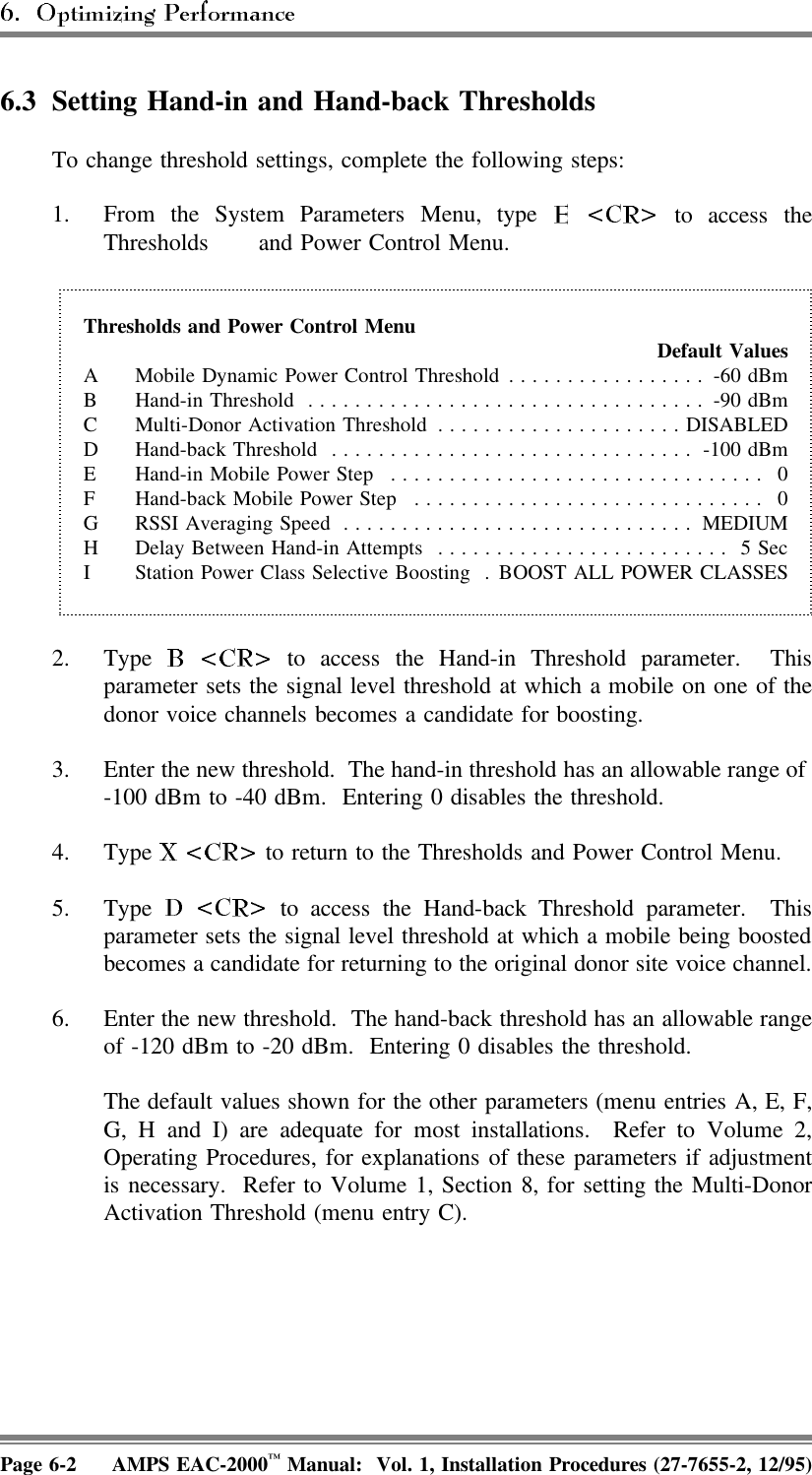
Andrew Wireless Innovations Group Cellular Repeater vol1eac200drev1b2
UserManual.wiki
>
Andrew Wireless Innovations Group
>
9GB2000 User Manual
users manual
Navigation menu
Upload a User Manual
Namespaces
Wiki Guide
HTML
PDF
Info
Views
User Manual
Discussion / Help
Navigation

![(Continued)4. Enter channels in the list, as described below. A given channelmay be entered in only one list. The system will support amaximum of 105 total channels in all four lists (A, B, C, andM).a. , type [channel number] .b. , after the enter multiplechannel numbers separated by commas or spaces. If youenter a plus (+) sign before a single channel entry, 15channels will be added, spaced 21 channels apart, startingwith the channel entered. You can then delete extrachannels as necessary.c. , type [channelnumber] .d. , after the enter multiplechannel numbers separated by commas or spaces. Toremove the entire list, type .5. To return to the Voice Channels Menu, type .Page 4-18 AMPS EAC-2000™ Manual: Vol. 1, Installation Procedures (27-7655-2, 12/95)](https://usermanual.wiki/Andrew-Wireless-Innovations-Group/9GB2000/User-Guide-53166-Page-88.png)

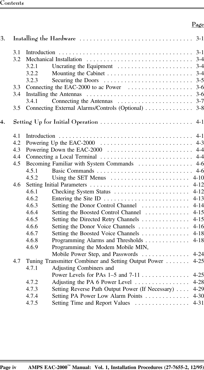
![6HFWLRQ 2SWLPL]LQJ3HUIRUPDQFH6.1 IntroductionAfter the EAC-2000 has been installed, the system must be checked out todetermine if adjustments to the hand-in ndk threholds eded to ensure optimumperformance.6.2 Determining Hand-in and Hand-back ThresholdsTo determine hand-in and hand-back thresholds, conduct coverage tests usingequipment whose power and antenna configuration match the predominatecustomer equipment in the coverage area. Conduct the tests as follows:1. Select the default hand-in and hand-back thresholds as a starting point forinitial system testing. These thresholds will serve adequately for manyinstallations.2. Test these thresholds throughout the coverage area from an automobilewith an outside cellular antenna. For best results, use a cellular mobilecapable of displaying received signal levels and the channel on which it isoperating. Make signal level measurements by monitoring the boostedcontrol channel. Make calls to a test number to determine whether the callis set up via the booster or whether the mobile is being handed in or outof the boosted area.Make sure the hand-back threshold is at least 5 dB below the hand-inthreshold. Setting the thresholds too low or too high can result in thefollowing types of problems:• Unnecessary boosting of mobiles thatotherwise will have good service from the donor.• Missing some mobiles that needboosting.• Excessive noise on the call beforeit is handed back to the original voice channel.• Too many hand-back attempts bythe EAC-2000.AMPS EAC-2000™ Manual: Vol. 1, Installation Procedures (27-7655-2, 12/95) Page 6-1](https://usermanual.wiki/Andrew-Wireless-Innovations-Group/9GB2000/User-Guide-53166-Page-109.png)
![(Continued)DONOR VOICE CHANNEL LISTS (5970–6030 Hz SAT)Entry:Main Menu ⇒Sys. Par. Menu ⇒Voice ChannelsMenu ⇒, , or Purpose: To display/change the list of donor voice channels, for thecorresponding SAT, which are scanned for mobile candidates to boost. Whenscanned, a candidate is verified as having the correct SAT before being boosted.Once the call is set up, the appropriate SAT is monitored.Allowable Range: • 1–799, 991–1023Making Entries:• Enter a given channel in only one list.• Entering channels in lists:- To add a channel: enter A [channel number] <CR>.- To add 15 channels spaced 48 channels apart, precede channelnumber with +. Remove unwanted channels. - To remove a channel, enter R [channel number] <CR>.- To add/remove multiple channels: enter A (add) or R (remove)[multiple channel numbers separated by commas or spaces] <CR>.• To change the SAT of a given channel, remove the channel from the oldSAT list, then add the channel to the new SAT list.Page 2-26 EAC-2000™ Manual: Vol. 2, Operating Procedures (27-7926-2, 12/95)](https://usermanual.wiki/Andrew-Wireless-Innovations-Group/9GB2000/User-Guide-53166-Page-172.png)
![6HFWLRQ 6SHFLDO&RPPDQGV4.1 IntroductionIn addition to the commands for system setup and monitoring (described inSections 2 and 3), there are special commands intended for hardwareverification. These lower-level commands are less "user friendly" than thecommonly used commands; their use requires detailed knowledge of thehardware and software. However, they are more flexible and therefore morepowerful. WARNING!! It is not recommended that these commands be usedin the field. Contact Allen Telecom Systems, Systems EngineeringDepartment, before using them.4.2 CommandsA summary of these commands is given below. In the command syntaxshown— • Each command is entered at the > prompt. • A, B, and C represent hex data to be entered.• Brackets [ ] enclose optional entries.Entry PurposeRFC Invokes a mode (signified by a # prompt) which allowscommunication with the RF boards directly. The protocolused is beyond the scope of this document. This commandmust be used with caution because it could destroypersonality and calibration data stored on the RF boards.Exit this command using ESC.RUN AAAA Causes program execution to begin at location AAAA inEPROM.CBY AAA[-BBBB] Displays Code BYte[s] (i.e., in EPROM) from locationAAAA [to BBBB] in hex.AMPS EAC-2000™ Manual: Vol. 2, Operating Procedures (27-7656-2, 12/95) Page 4-1](https://usermanual.wiki/Andrew-Wireless-Innovations-Group/9GB2000/User-Guide-53166-Page-239.png)
![4.2 Commands (Continued)Entry PurposeDBY AA[-BB][=CC] Displays Data BYte[s] in internal RAM from hex locationAA [to location BB], or if =CC is included, changes thebytes in the range to CC in hex.XBY AAAA[-BBBB][=CC] Displays/changes eXternal memory BYtes or memorymapped i/o in the range from AAAA [to BBBB].CHK Computes and displays the CHecKsum of program memory(i.e., uses the move instruction) and also displays the storedchecksum.WRP AAAA[=BB] Creates a continuous WRite Pulse to external memorylocation AAAA; data written is 55 hex or BB hex ifincluded. Exit this command by pressing ESC.RDP AAAA[-BBBB] Creates a continuous ReaD Pulse to external memorylocations in the range AAAA [to BBBB], and displays thevalues read on the screen (max of 15 locations displayed).Exit by pressing ESC.WAT Causes pulsing of the WATchdog timer to be suspended,thus allowing it to expire. A power-on reset should followshortly.Page 4-2 AMPS EAC-2000™ Manual: Vol. 2, Operating Procedures (27-7656-2, 12/95)](https://usermanual.wiki/Andrew-Wireless-Innovations-Group/9GB2000/User-Guide-53166-Page-240.png)