Andrew Wireless Innovations Group 9GB2000 Cellular Repeater User Manual vol1eac200drev1b2
Andrew Wireless Innovations Group Cellular Repeater vol1eac200drev1b2
users manual
EAC-2000 MANUAL ADDENDUM FOR DIGITAL OPERATION
D R A F T
15 July, 1999
1.1 Introduction
This section of the manual describes EAC-2000 operation when it has TIA-136
digital-channel sets installed. An EAC-2000 may be ordered directly from the
factory with digital channel sets installed, or upgrade kits may be ordered to add
digital channel-set capability to an existing EAC-2000 installation.
In general the installation issues (isolation needs, channel selection, etc.) are
identical for either type of system and are covered in detail in the AMPS EAC-2000
manual. The differences between a TIA-136 equipped system and a standard
AMPS-only system will be covered in this section.
The hardware differences for a digital-equipped EAC-2000 are:
1.1.1 Controller Module
Controller Module 19-20001-1 is required for TIA-136 digital operation. If an
existing EAC-2000 installation has the older (analog only) 19-5598-1 Controller
Module installed, it must be replaced with the dual-mode 19-20001-1 Controller
Module. The 19-20001-1 module will process both analog and digital calls.
1.1.2 RF Module
The 19-20000-1 IS-136 RF Module is required for TIA-136 operation. It may be
placed in any card cage slot in place of the analog 19-5599-1 Cellular I.F. module
within the following constraints:
• A 19-20000-1 module must be placed in slot 5 for DCCH operation.
• A 19-20000-1 module must be placed in slot 6 if dual-mode hand-in
operation is desired. If DCCH-only operation is implemented or if hand-
in of DTC calls is not required, then the analog 19-5599-1 Cellular I.F.
module may be left in slot 6.
• If dual-mode (analog control channel as well as a DCCH channel)
operation is desired, then an analog 19-5599-1 module must be installed in
slot 1 for the analog control channel.
• Any combination of 19-2000-1 IS-136 RF modules and 19-5599-1
Cellular I.F. modules may be placed in the remaining slots in the card
cage.
1.1.3 45W PA Module
The 1819.G1 class AB linear PA must be used with the 19-20000-1 module. The
class C PAs (21-117-1, 21-396-1, etc.) are usable only with the analog 19-5599-1
Cellular I.F. modules. Note also that the 1819.G1 linear PA cannot be used in
place of a class C PA. No power output will be provided in either case if the PA
is mismatched with its corresponding RF module.
Note that the 1819.G1 PA, the 19-20000-1 and the 19-20001-1 modules have
reverse-colored labels (white on blue instead of blue on white) to provide a quick
visual aid in identifying the modules required for TIA-136 operation. The
1819.G1 PA also has a label on its handle stating that it is an “IS-136 Linear PA”.
It is also white-on-blue to match the corresponding controller and RF module
labels.
1.2 Kit Contents
To allow field conversion of EAC-2000 installations to digital operation, two kits are
available:
If the EAC-2000 has a 19-5598-1 Controller module installed, then a EK2000DCCH
kit must be ordered. The EK2000ACCH kit consists of:
• One 19-20001-1 Controller Module
• One 19-20000-1 IS-136 RF Module
• One 1819.G1 IS-136 Linear PA
If the EAC-2000 has a 19-20001-1 Controller module installed, then an
EK2000DTC kit must be ordered. EK2000DTC kit consists of:
• One 19-20000-1 IS-136 RF Module
• One 1819.G1 IS-136 Linear PA
The EK2000DTC kit may be used for the DCCH channel if the EAC-2000 already
has the 19-20001-1 Controller Module installed. Otherwise, any number of
EK2000DTC kits may be ordered to add or increase DTC capacity in the EAC-2000.
Any shortage or apparent damage should be resolved before beginning the
installation.

1.3 Saving the existing System Configuration
If the Controller in an existing EAC-2000 installation is being upgraded to the 19-
20001-1 version, then many of the parameters programmed into the existing system
will also need to be copied to the new controller. To assist in this operation a blank
Parameter Worksheet is included in the appendix. This provides a place to list the
current setup parameters so that they can be entered as the new digital-capable
Controller is installed. The highlighted entries on the Parameter Worksheet are
digital-specific and will entered later.
Information on connecting a local terminal to the EAC-2000D is contained in Section
4.4 of Volume 1 of the EAC-2000 Manual.
1.4 Determining the Digital-specific Parameters
1.4.1 Identifying the Digital Donor Control Channel
The digital donor control channel is the IS-136 control channel of the primary cell
site with which the EAC-2000 will communicate. It can be used in conjunction with
an Analog Donor Control channel where both analog only and IS-136 mobiles are to
be served in the boosted coverage area.
•When the booster is adjacent to a single cell site, the control channel(s) of that
cell site is(are) the donor control channel(s).
•When the booster is adjacent to several cell sites, the control channel(s) of the
cell site with the most unused channels should be chosen. (This cell is then referred
to as the primary donor cell.) More than one cell site being received by a donor
antenna can result in unwanted hand-offs by the cellular system, causing dropped
calls. Therefore the donor antenna should be positioned to favor the desired donor
cell site. As in the analog case, the reverse-path signal level received from the EAC-
2000 by the adjacent cell sites must be less than the signal level received by the
selected donor site. Usually a 10 dB margin is sufficient.
•When both analog and digital donor channels are selected, it is best if they are
both from the same donor cell site as that makes positioning of the donor antenna
easier.
1.4.2 Selecting a Boosted Digital Control Channel
The boosted digital control channel (selection X) is the control channel that will be
used in the EAC-2000 coverage area. Select a channel that meets the following
requirements:
•At least a 3 channel separation from any donor channel (both control and
voice)
•At least a 21 channel separation from any boosted channel (both control and
voice). (Closer spacing is possible with higher losses, consult the factory)
•Conforms to the local system configuration. (Since IS-136 mobiles are
assisted in finding a DCCH, the system must be configured to add the
boosted Digital Control Channel to those information broadcasts). There are
several strategies in the cellular system setup that can assist mobile DCCH
selection. These are described in the appendix System Integration Issues
and Strategies.
1.4.3 Recording the digital parameters on the Parameter Worksheet
To make it easier to program the digital parameters into the system, they may be
entered onto the parameter worksheet. The digital parameters are highlighted so
they can be easily found.
2.0 Installing the new Hardware
This section of the manual details the installation of the hardware contained in the
DCCH kit. By convention the DCCH hardware is installed in slot 5, so any AMPS
hardware (PA and RF Module) currently installed in slot 5 must be removed or
relocated to another unused slot. The analog 19-5598-1 Controller will be removed
so it can be replaced with the 19-20001-1 IS-136 controller included in the DCCH
kit.
This upgrade will require the system be removed from service for a period of time
and should be scheduled to reduce impact on service.
2.1 Removing the AMPS hardware
Be sure that all current set-up information from the system has been recorded as
described in section 1.3 of this manual.
Slot 5 is the fifth position from the left in the RF/IF module card cage. The
corresponding PA position is the upper right slot in the lower (for a 10-channel
EAC-2000) PA cage. For a 5-channel EAC-2000, it is in the upper right slot of the
PA cage.
When no traffic is currently being handled by the booster shut off the booster.
Remove the Controller, RF module and PA that are currently in slot 5.
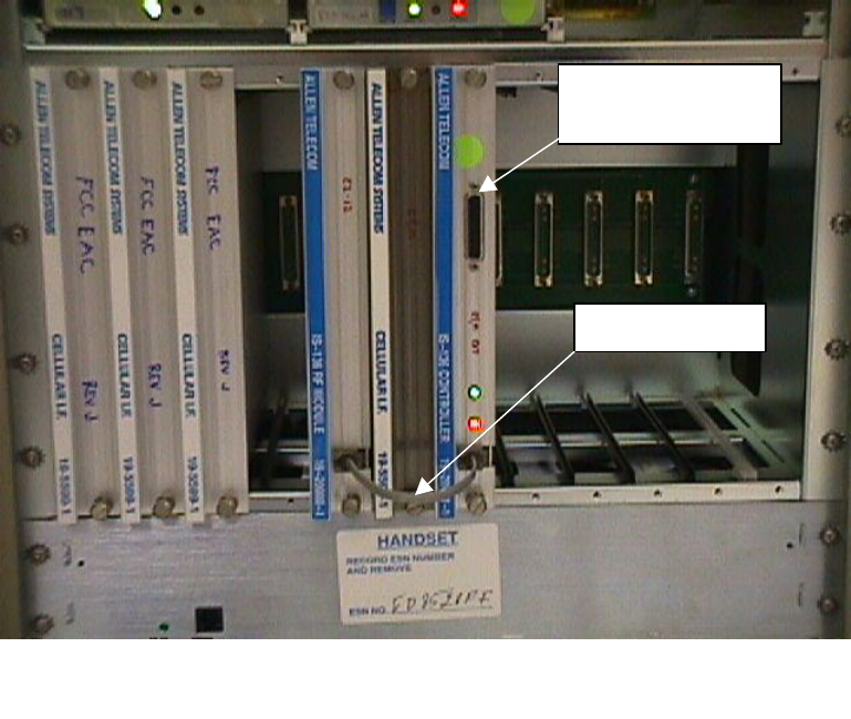
2.2 Installing the DCCH hardware
Install the 1819.G1 IS-136 PA into PA Slot 5
Install the 19-20000-1 IS-136 RF Module into IF slot 5
Install the IS-136 Controller into the controller slot
Connect the jumper cable from the IS-136 Controller to the IS-136 RF module as
shown in the detail Figure 1.
Verify all modules are fully seated, the retaining screws on the Controller and RF
Module are finger-tight, and the front-panel data cable is correctly installed between
the 19-20001-1 Controller and the 19-20000-1 IS-136 RF Module in slot 5.
If DTC kits are being installed, place the 19-20000-1 I.F. modules in the desired
slots. For DTC hand-in, a 19-20000-1 module must be placed in card cage slot 6.
19-20000-1 modules may be placed in any other available slot for DTC operation.
If analog control channel operation is to be provided, then an analog 19-5599-1
Cellular I.F. module must be left in card cage slot 1. If necessary, existing 19-5599-
1 analog modules may be removed to make room for the new 19-20000-1 digital
modules.
Note: The IS-136 PA(s) will be installed as part of the following procedure.
2.3 Preparing the AMPS hardware
Since the Controller contains all of the channel assignment information, when the
system is initially powered up with the 19-20001-1 Controller the system will
attempt to run with the factory defaults, causing a mismatch with the combiner
tuning. Therefore it is recommended that all the analog PA’s be pulled so that they
remain in their slot but do not make contact with the backplane connector. This
will effectively take them out of the system until the channels are correctly
programmed.
2.4 Connecting a Local Terminal
The IS-136 Controller uses the same RS-232 parameters and same style cable as the
original controller. Connect the terminal as follows.
1. Using the data cable that was provided with the EAC-2000, connect the
terminal to the 25-pin D-sub connector located on the front of the
controller module.
2. Power up the terminal and set it to the following parameters:
•9600 baud
•Even parity
•7 data bits, 1 stop bit
•Full duplex (no local echo)
If possible, also set the terminal to—
•All capitals
•Send carriage return only (no line feed)
•Disable AUTO XON/XOFF and soft scroll
If you are using a terminal emulation program, select TTY or VT100. Be
Local Terminal
Connector
Jumper Cable
Figure 1
Detail showing Local Terminal Connector and Installed Jumper Cable
aware that some terminal emulation programs generate extraneous characters
that may interfere with communicating with the EAC-2000.
3. Power up the EAC-2000. (After about 2 seconds, the terminal should respond
CONSOLE LOCKED.)
4. Enter <CR> (carriage return or enter, depending on the keyboard). (The
terminal should respond with a welcome message and prompt you for a
password.)
•If something comes up but is illegible, check the terminal setup.
• If nothing comes up, power down. Recheck the power hookup, the
terminal hookup, and the terminal setup.
5. Enter the password, followed by <CR>. The default password is 1234. (The
terminal should respond with more salutation and the > prompt.) The system
is ready for you to set parameters.
2.5 Configuring the System
Configuring the system consists of re-entering previous analog channel and setup
information as well as the new digital setup parameters into the IS-136 Controller.
To make this operation easier, the setup screens exactly parallel those used in the
AMPS EAC-2000, with additions to cover digital operation as needed. Since for
many systems the default values are acceptable, reprogramming of those values will
not be needed. The defaults for both the AMPS and digital-equipped EAC-2000 are
shown on the Parameter Worksheet.
2.6 Changes to the SET Menus for DCCH and DTC Operation
The following changes have been made to the SET menus to accommodate DCCH
and DTC operation:
1) In the RF Boards / Position X menu, STATUS parameter, the following choices
are now available (for all boards except board 6):
(0) DISABLED
(1) ENABLED AMPS Control
(2) ENABLED AMPS Voice
(3) ENABLED TDMA DCCH
(4) ENABLED TDMA DTC
For board 6, the choices are:
(0) DISABLED
(1) ENABLED Scan
Note that only one position Status may be set to ENABLED AMPS Control.
Also, only one position Status may be set to ENABLED TDMA DCCH
2) The Boosted Channel (whether it is voice, analog control or DCCH) is now set in
the RF Boards / Position X menu. For example, if you have the "Status" of a
board set to ENABLED TDMA DCCH, the position menu for that board will
display as follows:
Position 5
A Status ...............................ENABLED TDMA DCCH
B Boosted DCCH Channel ................. 169
C Diversity ............................ON
3) On the PA Menu, Selection K, "Key Forward PA" has been changed as follows.
If you select a PA number for which the associated Board STATUS is ENABLED
TDMA DCCH or ENABLED TDMA DTC, then you will be prompted to enter
the desired PA output power. The allowable range is 33 to 48 dBm in one dB
increments. In the case of the digital PA, there is no power adjustment screw.
Rather, the power out is controlled by software to be in a range of the PA power
set point - 0 to +0.5 dB.
Once you have entered the desired power out, the PA will be keyed, and the PA
power out reading will be displayed as usual. During this display, the PA power
out setting may be adjusted up or down by entering "U" or "D". This allows the
power out to be adjusted to compensate for the varying losses in the combiner and
the duplexer such that the desired power out at the antenna connector can be
achieved.
Following is the display that occurs when a TDMA PA is keyed.
Enter your selection ...k
NOTE: Keying PA may cause calls to drop
and will disrupt service in the EAC coverage area.
Enter RETURN to exit or number of PA to key : 5
PA 5 is DTC or DCCH; PA Output is software controlled to a
target range of PA Power Setting +/- .3 dB ...
Current PA Power Setting is : +46.5 dBm
Enter new value (or RETURN if no change) ...
While keyed, Enter "U" or "D" to adjust the PA Power Setting ...
Current PA Power Setting is : +46.5 dBm
PA Position 5 Channel Number 169 PA Power +46.6 dBm
4) On the PA Menu, if any board has Status set to Enabled TDMA DCCH or
Enabled TDMA Voice, additional power settings appear. Following is the full PA
Menu.
Power Amplifiers
A Forward PA Power Step - Voice ..................0
B Forward PA Power Step - Control ................0
C Forward PA Power Step - Hand-off................0
D Forward PA Power Low Alarm Point - Voice........+40.0 dBm
E Forward PA Power Low Alarm Point - Control......+40.0 dBm
F Forward PA Power Low Alarm Point - Hand-off.....+40.0 dBm
G Reverse PA Power Set - Voice ...................+20 dBm
H Reverse PA Power Set - Control .................+20 dBm
I Reverse PA Power Low Alarm Point - Voice........+15 dBm
J Reverse PA Power Low Alarm Point - Control......+15 dBm
K Key Forward PA .................................POWER ADJ / COMBINER TUNING
L Key Reverse PA .................................POWER MEASUREMENT
M Forward PA Power Low Alarm Point - DCCH ........+40.0 dBm
N Reverse PA Power Set - DCCH ....................+20 dBm
O Forward PA Power Low Alarm Point - DTC .........+40.0 dBm
P Reverse PA Power Set - DTC .....................+20 dBm
X Done with this menu
Note that selections M through P are new. They allow setting of the Forward PA
Power Low Alarm Point and Reverse PA Power Set for DCCH and DTC boards
and PAs. These settings correspond in functionality to their counterparts for the
analog voice and control channels.
Note that there is no "Reverse PA Power Low Alarm Point" setting for the DTC
or DCCH reverse PAs. The TDMA boards perform closed loop power control and
reverse PA power out checking. There is still an alarm generated if the Reverse
PA power output is low, however, the threshold at which the alarm occurs is not
operator settable.
5) The Control Channels menu (under the System Parameters menu) has been
changed to accommodate extra settings for DCCH. The following additional
menu items will appear if a board Status is set to Enabled TDMA DCCH.
I Donor DCCH Channel ................................. 400
J DCCH Channel State During "All Channels Busy" ...... DIRECTED RETRY
The Donor DCCH Channel setting has obvious functionality.
The DCCH Channel State During "All Channels Busy" paramater has
function that controls the Boosted DCCH operation when all channels
are busy (or, if there is no Donor DCCH being received).
The available choices are as follows.
(1) Off
(2) DENY ACCESS, BUT COUNT
(3) BOOST ACCESSES
(4) DIRECTED RETRY
These selections are identical to the selections for the analog "Control Channel
State when All Channels Busy" parameter.
6) The Control Channels Menu no longer has a "Boosted Control Channel" selection.
This channel is now entered in the RF Board menu.
7) The Voice Channels Menu no longer has a "Boosted Voice Channels" selection.
These channels are now entered in the RF Board menu.
8) The RSSI Alarm Points menu under the Alarms menu has two new settings to
accommodate the DCCH. The new RSSI Alarm Points menu is as follows:
RSSI Alarm Points
A Donor Control Channel RSSI - High Alarm Point ........DISABLED
B Donor Control Channel RSSI - Low Alarm Point .........-80 dBm
C Donor Voice Channel RSSI - High Alarm Point ..........DISABLED
D Donor DCCH Channel RSSI - High Alarm Point ...........DISABLED
E Donor DCCH Channel RSSI - Low Alarm Point ............-80 dBm
Note that selections D and E are new. They allow the setting of the RSSI levels
that cause alarms for the Donor DCCH.
9) The PA power settings for the forward PA for DCCH and DTC have a resolution
of 0.1 dBm. Also, the settings for the analog PA's have been changed to have a
resolution of 0.1 dBm. The associated powers reported with the "SSS" command
and the "PWR" command will read with resolution of 0.1 dBm.
Note that the accuracy of this reading ultimately depends upon the calibration of
the sensor in the PA or or the M1 antenna power sensor. Typically, this accuracy
is +/- .75 dB.
The reason power out is reported with a resolution of 0.1 dB even though the
accuracy is no better than 0.75 dB is to allow small changes in output power to be
resolved and displayed. For example, if a reported power out changes from +46.7
dBm to +46.2 dBm in a short term, the appropriate conclusion to draw is that (1)
the power out initially was 46.7 +/- 0.75 dBm and (2) the power out dropped by
about 0.5 dB.
3.0 Tuning the Transmitter Combiner and Setting Output Power
The combiner must be tuned and the output power levels set whenever the boosted
channels are entered or changed. For the upgrade to DCCH at least the boosted
DCCH will be new and will require adjustment. Any other channel changes will
also require retuning.
Even if the DCCH is only new channel to be tuned, it is preferable to repeak the
combiner and verify the output power for the other channels.
3.1 Tuning the DCCH Combiner PA 5
1. With the system power OFF, connect power-measuring equipment to the M1
antenna port (see Figure XX). Be sure that PA 5 (the IS-136 PA) is fully seated).
Remove the cover plates from the forward combiner(s) to reveal the combiner
tuning screws. Then turn the power back on. Output power may be monitored
using a through-line wattmeter (or a wattmeter with a built-in load) to monitor
output power.
2. From the SET Main Menu, type B <CR> to display the Power Amplifiers Menu.
A Forward PA Power Step - Voice ..................0
B Forward PA Power Step - Control ................0
C Forward PA Power Step - Hand-off................0
D Forward PA Power Low Alarm Point - Voice........+40.0 dBm
E Forward PA Power Low Alarm Point - Control......+40.0 dBm
F Forward PA Power Low Alarm Point - Hand-off.....+40.0 dBm
G Reverse PA Power Set - Voice ...................+20 dBm
H Reverse PA Power Set - Control .................+20 dBm
I Reverse PA Power Low Alarm Point - Voice........+15 dBm
J Reverse PA Power Low Alarm Point - Control......+15 dBm
K Key Forward PA .................................POWER ADJ / COMBINER TUNING
L Key Reverse PA .................................POWER MEASUREMENT
M Forward PA Power Low Alarm Point - DCCH ........+40.0 dBm
N Reverse PA Power Set - DCCH ....................+20 dBm
O Forward PA Power Low Alarm Point - DTC .........+40.0 dBm
P Reverse PA Power Set - DTC .....................+20 dBm
X Done with this menu
3. Type K <CR> to key a forward PA.
4. Type 5 <CR> to key PA 5 and display the forward power output as measured at the
sensor.
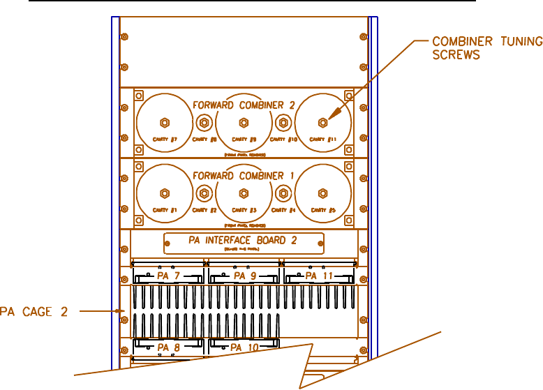
5. Refer to the illustration affixed to the inside of the front door of the EAC-2000
cabinet to determine which combiner cavities coordinate with which PAs. Loosen
the lock nut and adjust combiner cavity 5 using a screwdriver.
•If using a wattmeter, adjust for maximum power output as indicated by the
wattmeter.
•Retighten the lock nut.
NOTE: The power reading displayed on the terminal will not vary as the
combiner is tuned.
Combiner Cavity
6. Adjust the power output for PA 5 from the laptop computer as described in
paragraph 3) in section 2.6.
F NOTE: The PA power level displayed on the terminal is 3 to 4 dB
higher than the power level at the antenna port because of internal cable
and combiner losses. The displayed PA power ranges from +38 to +47
dBm (7–45 watts), which corresponds to a range at the M1 antenna
connector of +34 to +43 dBm (3–20 watts). If the displayed power level
is used instead of a wattmeter, take these differences into consideration.
Always use a wattmeter if an accurate power level reading at the M1
antenna connector is desired.
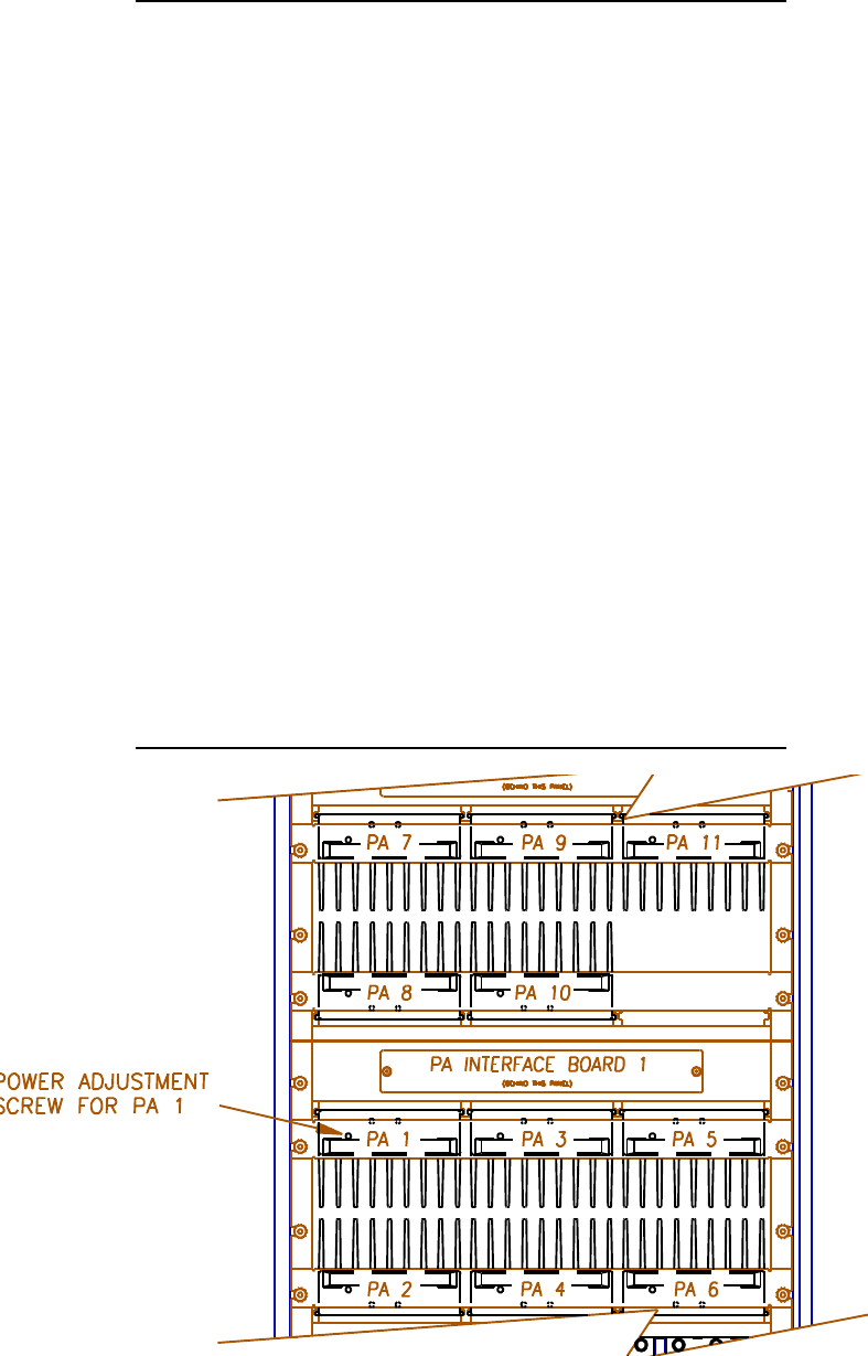
3.2 Adjusting Combiners and Power levels for PAs 1-4, and 7-11
In a like manner the combiner can be tuned for the remaining analog channels by selecting
a new PA each time. Each PA should be fully seated in its slot before proceeding. The
power level is set differently on the analog PA’s as follows:
1. Adjust the power output for each PA using a small screwdriver or adjustment tool to
turn the PA power potentiometer on the front of the PA (Figure 4-9). Use a
wattmeter, if available, to measure the power output. Adjust to the level necessary
to meet the authorized ERP level from the antenna.
F NOTE: The PA power level displayed on the terminal is 3 to 4 dB
higher than the power level at the antenna port because of internal cable
and combiner losses. The displayed PA power ranges from +38 to +47
dBm (7–45 watts), which corresponds to a range at the M1 antenna
connector of +34 to +43 dBm (3–20 watts). If the displayed power level
is used instead of a wattmeter, take these differences into consideration.
Always use a wattmeter if an accurate power level reading at the M1
antenna connector is desired.
Location of Analog PA Power Potentiometer
2. Note that the PA power potentiometer has a 7–10 dB turn down range. If the
power out cannot be adjusted low enough, hit ESC to return to the Power
Amplifiers Menu.
Select B, Forward PA Power Step - Control. This allows entry of a setting
between 0 and 3. Increasing the step by 1 causes the maximum power out to be
reduced by 4 dB (2→8 dB, 3→12 dB). Adjust this parameter in conjunction with
the potentiometer to achieve the desired output power.
3. Repeat steps 3 (selecting a new PA each time) through 7 to adjust the remaining
analog PAs (if installed).
If low power out is desired, use selection A, Forward PA Power Step - Voice, for
PAs 2–5 and 7–11.
4. When all PAs have been adjusted, make a second pass through the PAs to check
tuning and power levels, and make further adjustments as needed. This step is
needed because one of the cavities might have been close to the point to which a
second cavity was being tuned. This would cause erroneous power readings and
adjustment during the initial pass.
3.3 Adjusting the PA 6 Power Level
PA 6 output power does not pass through the combiner. (For a description of PA 6
function, see Section 2 of Volume 3, Technical Information.) To adjust its power
level—
1. Turn the power off, move the power measuring equipment to the M2 antenna port,
and turn the power back on.
If low power out of PA 6 is desired, use selection C, Forward PA Power Step -
Hand-off, to reduce the maximum power out.
NOTE: If a digital module is installed in slot 6, then use the procedure described in
paragraph 3) in section 2.6 for setting the power output level.
EAC-2000 Operating Parameters Work Sheet
Serial Number ____________________ (from “SSS” command)
RF Boards
1234567891011
Status _____ _____ _____ _____ _____ _____ _____ _____ _____ _____ _____
Diversity_____ _____ _____ _____ _____ _____ _____ _____ _____ _____ _____
Power Amplifiers
Forward PA Power Step - Voice _____
Forward PA Power Step - Control _____
Forward PA Power Step - Hand-off _____
Forward PA Power Low Alarm Point - Voice _____
Forward PA Power Low Alarm Point - Control _____
Forward PA Power Low Alarm Point - Hand-off _____
Reverse PA Power Set - Voice _____
Reverse PA Power Set - Control _____
Reverse PA Power Low Alarm Point - Voice _____
Reverse PA Power Low Alarm Point - Control _____
Site Id
Site Identification ______________
Multi-Hop Feature _____
Control Channels
Donor Control Channel _____
Boosted Control Channel _____
RF Board Pair to Use for Control _____
Control Channel State _____
Directed Retry Channels 1_____ 2_____ 3_____ 4_____ 5_____ 6_____
Backup Control Channel Option _____
Revertive Control Channel Option _____
• Substitute Control Channel _____
• Booster Link Channel _____
• These selections only appear if Backup Control Channel is enabled or if Multi-Hop mode
3 or 4 is selected.
Voice Channels
Boosted Voice Channel 2 ____ 3 ____ 4 ____ 5 ____ 7 ____ 8 ____ 9 ____ 10 ____ 11 ____
Donor Voice Channels
5970 Hz SAT 6000 Hz SAT 6030 Hz SAT
____ ____ ____ ____ ____ ____ ____ ____ ____
____ ____ ____ ____ ____ ____ ____ ____ ____
____ ____ ____ ____ ____ ____ ____ ____ ____
____ ____ ____ ____ ____ ____ ____ ____ ____
____ ____ ____ ____ ____ ____ ____ ____ ____
____ ____ ____ ____ ____ ____ ____ ____ ____
____ ____ ____ ____ ____ ____ ____ ____ ____
____ ____ ____ ____ ____ ____ ____ ____ ____
____ ____ ____ ____ ____ ____ ____ ____ ____
____ ____ ____ ____ ____ ____ ____ ____ ____
Modem Control
Master Password ________________
Restricted Password ____________
Console Timeout _____
Auto Dial Enable _____
Dial-up Phone Number 1 __________________________
Dial-up Phone Number 2 __________________________
Auto Dial Trials Max _____
Max Auto Dial Trial Period _____
Delay Between Auto Dial Trials _____
Modem Mobile MIN ________________
Modem Mobile Power step _____
Modem Setup
NOTE: Record these strings before the upgrade, but do NOT reenter them after version 2X.03 or
later is installed. Versions 2X.03 and later have new default strings that allow the remote link to
run at high baud rates and to use error correction.
Init String __________________________
Dial Command _________________________
Hangup String _______________________
Local Port Baud Rate _____
Local Port Comm Params _____
Remote Port Baud Rate _____
Remote Port Comm Params _____
Thresholds and Power Control Menu
Mobile Dynamic Power Control Threshold _____
Hand-in Threshold _____
Multi-Donor Activation Threshold _____
Hand-back Threshold _____
Hand-in Mobile Power Step _____
Hand-back Mobile Power Step _____
RSSI Averaging Speed _____
Delay Between Hand-in Attempts _____
Station Power Class Selective Boosting ___________
Call Disconnect Parameters
Donor RSSI _____
Sat Fade Timeout _____
Max Number of Hand-back Attempts _____
Minimum Delay Between Hand-back Attempts _____
Call Processing Parameters Menu
Mobile RSSI > Threshold Parameters _____
Hand-back Grab-back Control _____
Alarms Menu
Antenna Return Loss - Low Alarm Point _____
PA to Antenna Return Loss - High Alarm Point _____
PA Temp - High Alarm Point _____
PA Temp - Fan Activation Point _____
PA Temp - PA Power Cutback Point _____
Power Control Causes PA Power Cutback _____
+28 Volt Supply - PA Power Cutback Point _____
+28 Volt Supply - Low Alarm Point _____
+12 Volt Supply - Low Alarm Point _____
+6 Volt Supply - Low Alarm Point _____
External Analog Inputs Menu
PA 1-6 Cage: PA 7-11 Cage:
Ext. Analog Input 1 Alarm State _____ Ext. Analog Input 1 Alarm State _____
Ext. Analog Input 2 Alarm State _____ Ext. Analog Input 2 Alarm State _____
Ext. Analog Input 3 Alarm State _____ Ext. Analog Input 3 Alarm State _____
Ext. Analog Input 4 Alarm State _____ Ext. Analog Input 4 Alarm State _____
External Digital Inputs Menu
PA 1-6 Cage: PA 7-11 Cage:
Ext. Digital Input 1 Alarm State _____ Ext. Digital Input 1 Alarm State _____
Ext. Digital Input 2 Alarm State _____ Ext. Digital Input 2 Alarm State _____
Ext. Digital Input 3 Alarm State _____ Ext. Digital Input 3 Alarm State _____
Ext. Digital Input 4 Alarm State _____ Ext. Digital Input 4 Alarm State _____
External Digital Outputs Menu
PA 1-6 Cage: PA 7-11 Cage:
Ext. Digital Output 1 State _____ Ext. Digital Output 1 State _____
Ext. Digital Output 2 State _____ Ext. Digital Output 2 State _____
Ext. Digital Output 3 State _____ Ext. Digital Output 3 State _____
Ext. Digital Output 4 State _____ Ext. Digital Output 4 State _____
Critical Alarms
(NOTE: default values for these are shown)
Board Out-of-Service Alarm...........................................CRITICAL ___________
Board ROM Alarm.........................................................CRITICAL ___________
Board Calibration Memory Alarm ..................................CRITICAL ___________
Serial Data Link Alarm ..................................................CRITICAL ___________
Personality Mismatch Alarm...........................................CRITICAL ___________
Synthesizer Unlocked Alarm ..........................................CRITICAL ___________
RVS PA PWR Low Alarm ............................................ CRITICAL ___________
RSSI Alarm ...................................................................LOG ONLY ___________
PA Out-of-Service Alarm ..............................................CRITICAL ___________
PA TEMP - High Alarm ................................................CRITICAL ___________
PA Power - Low Alarm ................................................. CRITICAL ___________
PA to Antenna Loss High Alarm ...................................CRITICAL ___________
Antenna RET Loss Alarm .............................................. CRITICAL ___________
ROM Alarm ..................................................................CRITICAL ___________
RAM Alarm ..................................................................CRITICAL ___________
NOVRAM Alarm .......................................................... CRITICAL ___________
SAT Detector Alarm ...................................................... CRITICAL ___________
Power Supply Voltages - Low Alarm..............................CRITICAL ___________
External Analog Input Alarm.......................................... LOG ONLY ___________
External Digital Input Alarm ..........................................LOG ONLY ___________
RSSI Alarm Points
Donor Control Channel RSSI - High Alarm Point NONE _____
Donor Control Channel RSSI - Low Alarm Point -80 dBm _____
Forward Voice Channel RSSI - High Alarm Point NONE _____

$036
($& 0DQXDO
Installation • Operation • Technical
Order No. 27-7654-3
Issue 12/95
© Copyright 1995 Allen Telecom Systems
All Rights Reserved
Field Support
If you need technical assistance with the EAC-2000™, contact
at one of the following telephone numbers:
Extend-A-Cell : (800) 800-EAC4 (3224)
or (216) 349-8413
Systems Engineering Department: (216) 349-8413
The AMPS EAC-2000™ Manual (Order No. 27-7654-3, 12/95) includes the
following:
27-7655-2 Volume 1, Installation Procedures
27-7656-2 Volume 2, Operating Procedures
27-7657-2 Volume 3, Technical Information
27-7658-3 Appendices
27-7659-2 Glossary and Index
27-7660-1 Parts and Accessories Ordering Information
ii

LIMITED WARRANTY
ALLEN TELECOM SYSTEMS, a Division of the ALLEN TELECOM GROUP,
INC. ("ALLEN TELECOM") warrants, on the terms and conditions hereto set forth,
all products manufactured by it to be free under normal use and service from defects
in materials and workmanship for a period of one (1) year from the date of shipment,
to the first consumer (the "Warranty Period").
ALLEN TELECOM’s obligation under this Limited Warranty is limited to prompt
repair or replacement of the product, at its option, without charge, at an authorized
ALLEN TELECOM dealer or at the factory of ALLEN TELECOM in Cleveland,
Ohio, when the product is returned to an authorized dealer or to the factory with all
transportation charges prepaid and examination of the product shall disclose it to have
been defective in the respects aforesaid during the Warranty Period.
The Limited Warranty shall not be extended beyond its original term with respect
to any part or parts repaired or replaced by ALLEN TELECOM hereunder.
The Warranty Period shall not apply to any product which has been repaired or
altered in any manner by anyone other than ALLEN TELECOM or an authorized
outlet of ALLEN TELECOM, or if the defect, malfunction or failure of the product
was caused by damage by lightning, flood or other acts of nature or by power surges,
or from unreasonable use, or from improper installation or application, or to any
product which has not been maintained or used in accordance with the operating
specifications set forth in ALLEN TELECOM’s written instructions.
IMPLIED WARRANTIES OF MERCHANTABILITY OR FITNESS FOR ANY
PARTICULAR PURPOSE ARE LIMITED IN DURATION TO THE WARRANTY
PERIOD SPECIFIED ABOVE.
UNDER NO CIRCUMSTANCES SHALL ALLEN TELECOM BE LIABLE FOR
ANY CONSEQUENTIAL DAMAGES FOR BREACH OF THIS WARRANTY OR
OF ANY IMPLIED WARRANTY.
Some states do not allow limitation on how long an implied warranty lasts, so the
above limitation may not apply to you. Some states do not allow the exclusion or
limitation of incidental or consequential damages, so the above limitation or exclusion
may not apply to you. This Warranty gives you specific legal rights, and you may
also have other rights which vary from state to state.
ALLEN TELECOM neither assumes nor authorizes any person to assume for it
any obligation or liability other than as herein expressly stated.
iii
&RQWHQWV
Quick Start Checklist...................................... ix
1. Introduction ........................................ 1-1
2. Preliminary Decisions ................................. 2-1
3. Installing the Hardware ................................ 3-1
4. Setting Up for Initial Operation .......................... 4-1
5. Installing the Remote Link .............................. 5-1
6. Optimizing Performance ............................... 6-1
7. Multi-Hop™ Operation ................................. 7-1
8. Operation with Multi-Donor™ Units ....................... 8-1
9. RESERVED FOR FUTURE USE ......................... 9-1
10. Combined Operation: Multi-Hop / Multi-Donor.............. 10-1
1. Introduction ........................................ 1-1
2. SET Command...................................... 2-1
3. System Monitoring Commands .......................... 3-1
4. Special Commands ................................... 4-1
1. Introduction ........................................ 1-1
2. EAC-2000™ Description ............................... 2-1
3. Specifications and Drawings ............................ 3-1
A. Troubleshooting Guide ................................A-1
B. Isolation .......................................... B-1
C. Reference Oscillator Adjustment .......................... C-1
........................................... Glossary-1
................................................ Index-1
.......................Parts-1
AMPS EAC-2000™ Manual (27-7654-3, 12/95) Page v
v

9ROXPH
,QVWDOODWLRQ3URFHGXUHV
27-7655-2
Issue 12/95
© Copyright 1995 Allen Telecom Systems
All Rights Reserved

Field Support
If you need technical assistance with the AMPS EAC-2000™, contact
at one of the following telephone numbers:
Extend-A-Cell : (800) 800-EAC4 (3224)
or (216) 349-8413
Systems Engineering Department: (216) 349-8413

Contents
............................................ vi
.......................................vii
.......................................... 1-1
1.1 About This Volume ................................. 1-1
1.1.1 Contents .................................. 1-1
1.1.2 Terminology ............................... 1-3
1.2 About the AMPS EAC-2000™.......................... 1-4
1.2.1 Use of Boosters............................. 1-4
1.2.2 Frequency Allocation ......................... 1-4
1.2.3 EAC-2000 Operation ......................... 1-4
................................... 2-1
2.1 Introduction ....................................... 2-1
2.2 Use of Multi-hop™ Configuration or Multi-donor™ Units ........ 2-2
2.3 Site Requirements ................................... 2-2
2.3.1 Location .................................. 2-2
2.3.2 ac Service ................................. 2-3
2.3.3 Space .................................... 2-3
2.3.4 Mounting Surface ........................... 2-4
2.4 Antennas ......................................... 2-4
2.4.1 Type .................................... 2-5
2.4.2 Placement ................................ 2-6
2.4.3 Measuring Signal Level and Isolation .............. 2-9
2.5 Selecting Channels ................................. 2-11
2.5.1 Identifying the Donor Control Channel ............ 2-11
2.5.2 Selecting a Boosted Control Channel ............. 2-12
2.5.3 The Revertive Control Channel Option............ 2-13
2.5.4 The Substitute Control Channel ................. 2-13
• Disabling the Substitute Control Channel ...... 2-14
• Enabling the Substitute Control Channel ....... 2-14
2.5.5 Selecting the Directed Retry Channels ............ 2-15
2.5.6 Selecting Donor Voice Channels ................ 2-16
2.5.7 Selecting Boosted Voice Channels ............... 2-17
AMPS EAC-2000™ Manual: Vol. 1, Installation Procedures (27-7655-2, 12/95) Page iii

................................. 3-1
3.1 Introduction ....................................... 3-1
3.2 Mechanical Installation ............................... 3-4
3.2.1 Uncrating the Equipment ...................... 3-4
3.2.2 Mounting the Cabinet......................... 3-4
3.2.3 Securing the Doors .......................... 3-5
3.3 Connecting the EAC-2000 to ac Power ................... 3-6
3.4 Installing the Antennas ............................... 3-6
3.4.1 Connecting the Antennas ...................... 3-7
3.5 Connecting External Alarms/Controls (Optional) .............. 3-8
........................... 4-1
4.1 Introduction ....................................... 4-1
4.2 Powering Up the EAC-2000 ........................... 4-3
4.3 Powering Down the EAC-2000 ......................... 4-4
4.4 Connecting a Local Terminal ........................... 4-4
4.5 Becoming Familiar with System Commands ................ 4-6
4.5.1 Basic Commands............................ 4-6
4.5.2 Using the SET Menus ....................... 4-10
4.6 Setting Initial Parameters ............................. 4-12
4.6.1 Checking System Status ...................... 4-12
4.6.2 Entering the Site ID ......................... 4-13
4.6.3 Setting the Donor Control Channel .............. 4-14
4.6.4 Setting the Boosted Control Channel ............. 4-15
4.6.5 Setting the Directed Retry Channels .............. 4-15
4.6.6 Setting the Donor Voice Channels ............... 4-16
4.6.7 Setting the Boosted Voice Channels .............. 4-18
4.6.8 Programming Alarms and Thresholds............. 4-18
4.6.9 Programming the Modem Mobile MIN,
Mobile Power Step, and Passwords .............. 4-24
4.7 Tuning Transmitter Combiner and Setting Output Power ....... 4-25
4.7.1 Adjusting Combiners and
Power Levels for PAs 1–5 and 7-11 .............. 4-25
4.7.2 Adjusting the PA 6 Power Level ................ 4-28
4.7.3 Setting Reverse Path Output Power (If Necessary) .... 4-29
4.7.4 Setting PA Power Low Alarm Points ............. 4-30
4.7.5 Setting Time and Report Values ................ 4-31
Page iv AMPS EAC-2000™ Manual: Vol. 1, Installation Procedures (27-7655-2, 12/95)
............................... 5-1
5.1 Introduction ....................................... 5-1
5.2 Setting Up Service .................................. 5-3
5.3 Programming the Mobile Radio ......................... 5-4
5.4 Checking Out the Mobile.............................. 5-4
5.5 Testing the Remote Link .............................. 5-5
5.5.1 EAC-2000 Answering ........................ 5-5
5.5.2 EAC-2000 Originating ........................ 5-6
................................ 6-1
6.1 Introduction ....................................... 6-1
6.2 Determining Hand-in and Hand-back Thresholds ............. 6-1
6.3 Setting Hand-in and Hand-back Thresholds ................. 6-2
.................................. 7-1
7.1 Introduction ....................................... 7-1
7.2 How Multi-Hop Operation Works ........................ 7-1
7.3 Installing the EAC-2000 in Multi-Hop Configuration .......... 7-2
7.3.1 Achieving Antenna Isolation and Signal Level ........ 7-3
7.3.2 Enabling the Multi-Hop Feature ................. 7-3
7.3.3 Selecting Boosted Channels for Each Unit .......... 7-4
7.3.4 Setting the Hand-back Threshold ................. 7-6
7.3.5 Reviewing the Hand-in Threshold ................ 7-9
........................ 8-1
8.1 Introduction ....................................... 8-1
8.1.1 Purpose of Multi-Donor Units ................... 8-1
8.1.2 MDU Operation ............................. 8-2
8.2 Installing the EAC-2000 for MDU Operation ................ 8-2
8.2.1 Achieving Adequate Signal Level at the EAC-2000 .... 8-3
8.2.2 Achieving Adequate Signal Level at the MDU ....... 8-3
8.2.3 Setting the Multi-Donor Activation Threshold ........ 8-4
8.2.4 Assigning a Booster Link Channel................ 8-4
AMPS EAC-2000™ Manual: Vol. 1, Installation Procedures (27-7655-2, 12/95) Page v

. 10-1
10.1 Introduction ...................................... 10-1
10.2 Installing the EAC-2000 for Combined Operation ............ 10-2
10.2.1 Requirements ............................. 10-2
10.2.2 Channel Assignments ........................ 10-2
1-1. Important Terms Used in This Manual....................... 1-3
1-2. System Operation ..................................... 1-5
2-1. Pre-Installation Checklist ................................ 2-1
2-2. Recommended Space................................... 2-3
2-3 Typical Antenna Installation .............................. 2-8
2-4 Antenna Isolation v. Horizontal Separation .................... 2-9
2-5 Antenna Isolation v. Vertical Separation ..................... 2-10
3-1. Hardware Installation Checklist ............................ 3-2
3-2. EAC-2000, Front View (Door Removed) ..................... 3-2
3-3. EAC-2000, Back View (Door Removed) ..................... 3-3
3-4. Outdoor Cabinet Footprint ............................... 3-4
3-5. Antenna Connectors .................................... 3-7
3-6. External Alarm/Control Connector Pin Out .................... 3-8
3-7. Electrical Specifications for Inputs and Outputs ................. 3-9
3-8. Typical Wiring for External Inputs and Outputs ............... 3-11
4-1. Setup Checklist ....................................... 4-2
4-2. EAC-2000 Breakers .................................... 4-3
4-3. Breaker Locations ..................................... 4-3
4-4. Location of Local Terminal Connector ....................... 4-4
4-5. Command Definitions .................................. 4-6
4-6. System Commands .................................... 4-8
4-7. SET Command Menu Map.............................. 4-11
4-8. Combiner Cavity .................................... 4-25
4-9. Location of PA Power Potentiometer ....................... 4-27
5-1. Remote Link Installation Checklist ......................... 5-3
7-1. Example of Valid Channel Set ............................ 7-5
10-1. Combined Configuration Example......................... 10-1
10-2. Channel Assignment Example............................ 10-3
Page vi AMPS EAC-2000™ Manual: Vol. 1, Installation Procedures (27-7655-2, 12/95)
Quick Start Checklist
Quick Start Checklist
This checklist provides a brief summary of steps for starting up the AMPS EAC-
2000™. For detailed instructions, see Sections 1–6. For special configurations and
options, see Sections 7–10.
(See Section 2)
4 antennas: M1, M2, D1 and mobile
Isolation: greater than 75 dB measured between D1 and M1, M2.
Signal level: -75 dBm or greater from donor on D1 antenna.
ac power: 240 V/20 A service wired to power panel in rear.
Channel separation: Boosted channel set assigned with no boosted
channel closer than 3 channels (90 kHz) to any donor channel.
Separation by 150 kHz is recommended.
Mobile MIN assigned for programming of modem mobile.
Donor channels: Have list of donor channels and SAT ready.
(See Section 4)
1. Connect terminal or computer RS-232 port to 25-pin D female connector
on controller board using supplied cable. Set up terminal for 9600-E-7-1,
no CTS/RTS, no X-on/X-off.
2. Turn on rear panel ac breaker.
3. Turn on power supply ac breaker(s). Be sure the 6/12 V power switch
is on.
4. The terminal should "come alive" and display CONSOLE LOCKED.
Press
ENTER, and receive the banner showing the firmware revision and
the unit serial number. At the password prompt, enter the default
password
1234 and <CR>.
Continued . . .
AMPS EAC-2000™ Manual: Vol. 1, Installation Procedures (27-7655-2, 12/95) Page vii

Quick Start Checklist
(See Sections 4, 5, and 6)
1. Type SSS <CR>. (Nothing should show DISABLED. If anything shows
disabled, refer to Appendix A, Troubleshooting Guide.)
2. Type ALA <CR>. (There should be no alarms. If there are any OUT
OF SERVICE or memory alarms, refer to Appendix A.)
3. Type SET <CR> and go into submenu C, System Parameters.
4. Enter submenu A and program the site ID.
5. Enter submenu B and program the donor and boosted control channels.
Decide how the control channel is to act when all channels are busy.
6. Enter submenu C and program the boosted voice channel numbers for
channels 2–5 and 7-11, if installed.
7. Program the donor voice channels into list A, B, or C, depending upon
the SAT used at the donor. To enter a 15-channel set, enter a plus sign
(+) before the first channel number. Delete unneeded channels.
8. Enter the Modem Control submenu D and program the modem mobile
MIN that has been assigned. Calls made to and from this number will
not be transferred to the booster, but will be trapped-out and handled
directly by the donor. Also set the modem mobile power step to the
desired level.
9. Turn off the system power and connect power measuring equipment to the
M1 antenna port. Turn system power back on. From the SET Main
menu, enter submenu B, Power Amplifiers. Select menu entry K (Key
Forward PA) for combiner tuning. Select amplifiers 1-5 and 7-11, if
installed. Use a screwdriver to adjust the combiner for maximum power
output. Use a small screwdriver or adjusting tool to adjust the PA power
pot on the front of each PA for desired power out of the unit.
10. Turn off the system power, connect the power measuring equipment to
the M2 antenna port, and turn the system power back on. From the SET
Main Menu, enter submenu B, Power Amplifiers. Select menu entry K
(Key Forward PA) for combiner tuning and select PA 6. Adjust the
power to be equal to the voice channel power.
11. Remove the test equipment and use <CTRL> X to exit the SET menu
completely. Press
<CR> at the question prompt.
Continued . . .
Page viii AMPS EAC-2000™ Manual: Vol. 1, Installation Procedures (27-7655-2, 12/95)
Quick Start Checklist
(Continued)
12. From the command entry level >, use the TIM command to set the date
and time.
13. From the command entry level >, enter DCS=0, DCH=0, and ALA=0 to
reset the report values.
1. Connect the 4 antennas. The unit is now operational!
2. Type SCS <CR> and make some calls. You will see your MIN
displayed on call originations and answers.
3. Connect the handset to the connector on the front of the mobile shelf (see
Section 5).
4. Program hand-in/hand-back thresholds as desired (see Section 6).
5. After completing installation and setup, secure cabinet doors.
See Sections 7–10 for special configurations and options.
AMPS EAC-2000™ Manual: Vol. 1, Installation Procedures (27-7655-2, 12/95) Page ix
6HFWLRQ ,QWURGXFWLRQ
1.1 About This Volume
This volume, the first of three volumes pertaining to the AMPS EAC-
2000™, contains detailed procedures for installing the EAC-2000.
This volume has been divided into a Quick Start Checklist and 12
sections, described below. Volume 2 contains operating procedures,
and Volume 3 contains technical information. A set of appendices
(described below), a glossary, and an index accompany the three
volumes.
• Brief summary of installation and
setup procedures.
• Contents of this volume, key terms,
and a general introduction to the AMPS EAC-2000.
• Factors to consider before
you begin installation.
• Procedures for
mechanical, electrical, and antenna installation and connection
of external alarms or controls.
• Procedures for
powering up the system, connecting a local terminal,
programming parameters, tuning the transmitter combiner, and
setting output power.
• Procedures for
setting up, programming, and checking out the mobile, and
testing the remote link.
• Procedures for setting
hand-back and hand-in thresholds to optimize booster
performance.
AMPS EAC-2000™ Manual: Vol. 1, Installation Procedures (27-7655-2, 12/95) Page 1-1
(Continued)
• Procedures for installing
the EAC-2000 in a Multi-Hop chain.
• Special
installation procedures when using the EAC-2000 with Multi-
Donor Units.
•
•
• Recommendations for
resolving selected installation and operation problems.
• Recommendations for achieving
antenna isolation.
Procedures for ordering
parts and accessories for units that are under warranty and for units
on which the warranty has expired.
For detailed descriptions of all EAC-2000 operating parameters and
procedures for setting them, refer to Volume 2. For a more detailed
description of the EAC-2000 and how it works, refer to Volume 3.
Page 1-2 AMPS EAC-2000™ Manual: Vol. 1, Installation Procedures (27-7655-2, 12/95)
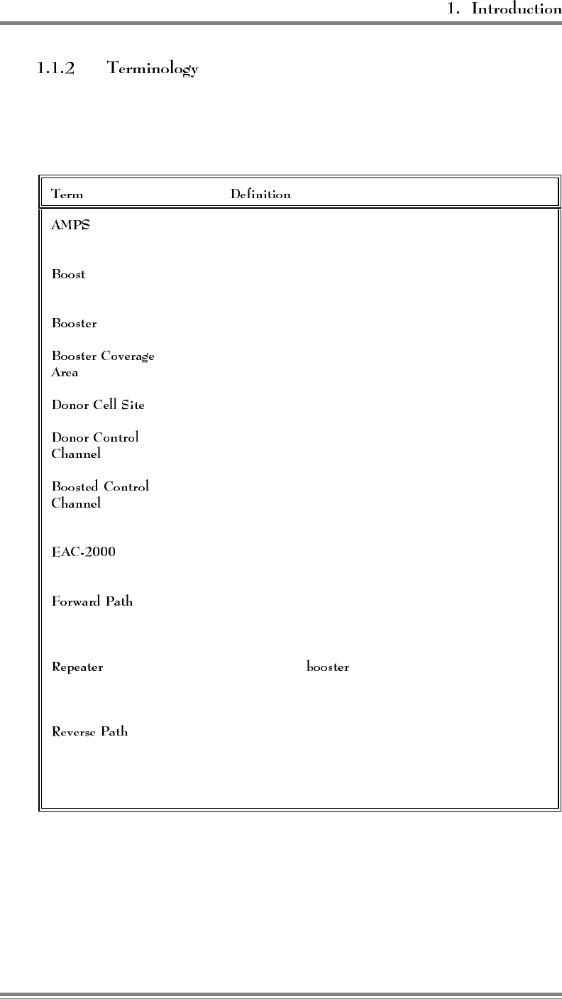
Figure 1-1 lists key terms used in this volume. Additional terms and
acronyms are defined in the Glossary.
Figure 1-1. Important Terms Used in This Manual
Advanced Mobile Phone System. Cellular standard that provides
compatible operation in the 824–849 and 869–894 MHz band.
To receive, amplify, and reradiate signals to fill in weak
coverage areas.
A system that boosts or repeats.
The area where subscribers obtain coverage through the
booster.
The cell site in communication with the booster.
The control channel used between the cell site and the booster
(and all the mobiles in direct contact with the cell site).
The control channel used between the booster and the mobile
in the booster coverage area (a different frequency than the
donor control channel).
™The trademarked name for a booster made by Allen Telecom
Systems.
The path taken by the RF signal transmitted by the donor cell,
which is received, amplified, and reradiated by a booster and
received ultimately by a subscriber in the booster coverage area.
Synonymous with , usually applied to boosters that
translate frequencies. The EAC-2000 is type-accepted as a
repeater.
The path taken by the RF signal transmitted by a subscriber
mobile in the booster coverage area, which is received,
amplified, and reradiated by a booster and received ultimately by
the donor cell site.
AMPS EAC-2000™ Manual: Vol. 1, Installation Procedures (27-7655-2, 12/95) Page 1-3
1.2 About the AMPS EAC-2000
This section provides a brief overview of how the EAC-2000 operates. For a
more detailed discussion, refer to Volume 3, Technical Information.
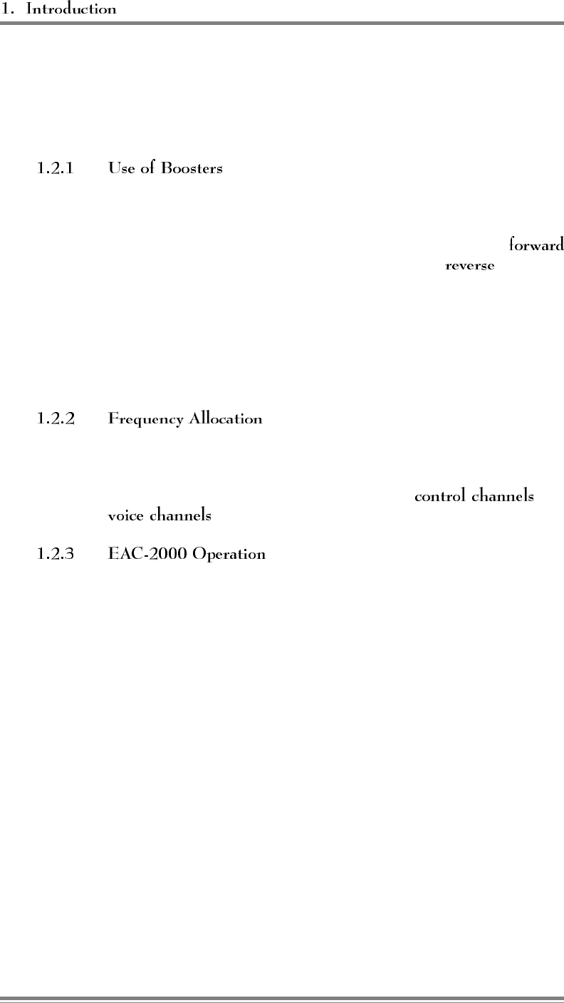
Cellular telephone systems transmit signals in two directions between
cell sites and mobile telephones within the signal coverage area. The
signal path from the cell site to the mobiles is called the
path, and the path from mobiles to cell site is the path.
If weak signal transmissions occur within the coverage area because
of indoor applications, terrain obstructions, or distance from the
transmitter, a relatively inexpensive way to extend transmission range
is to install a signal booster that receives the signal, amplifies it, and
reradiates it. (See Figure 1-2.)
AMPS cellular systems use 824–849 MHz for reverse and 869–894
MHz for forward transmissions. These frequency bands are divided
into systems A and B, each with designated and
.
The EAC-2000 booster uses up to 21 individual narrowband
amplifiers: 1 (reverse) for the control channel, up to nine (forward
and reverse) for voice channels, and one amplifier (forward only) for
hand-in and data message transmissions. The reverse half of this
board acts as a locate receiver. There are two amplifiers for each IF
board (forward and reverse); each is a single channel (30 kHz) wide
and has dual synthesizers that control input and output channels
independently.
The simplified diagram in Figure 1-2 illustrates one board (forward
and reverse paths) being used for the control channel, and one board
(forward and reverse) being used for one voice channel.
Page 1-4 AMPS EAC-2000™ Manual: Vol. 1, Installation Procedures (27-7655-2, 12/95)
(Continued)
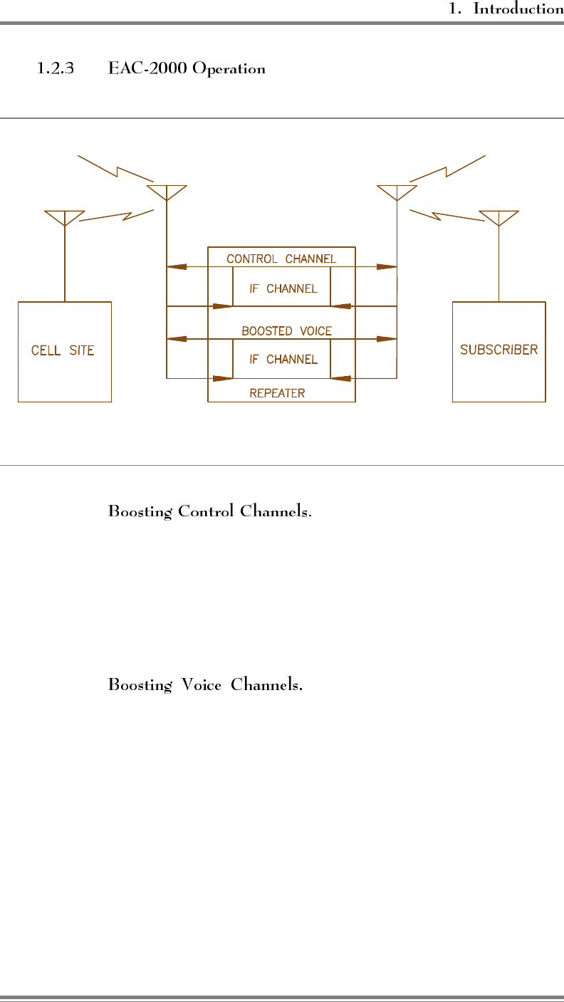
Figure 1-2. System Operation
The EAC-2000 monitors the donor
control channel to obtain system-specific information. It generates a
control channel data stream and transmits it on another control
channel frequency. Mobiles that are unable to receive the original
channel then lock onto the boosted control channel and communicate
with the cell site through the booster. Control channel translation is
possible because the mobiles always lock onto the strongest control
channel.
The amplifiers for boosting voice
channels are keyed as needed when voice channel activity is detected
in the boosted coverage area. The EAC-2000 identifies mobiles in
the booster coverage area by two methods: one for identifying
mobiles that place or answer calls from within the booster coverage
area and another for identifying mobiles that enter the area with a call
in progress.
AMPS EAC-2000™ Manual: Vol. 1, Installation Procedures (27-7655-2, 12/95) Page 1-5
(Continued)
When a call is placed or answered from within the booster coverage
area, the following sequence occurs:
1. The mobile accesses the reverse boosted control channel. The
EAC-2000 receives the access, then accesses the reverse donor
control channel.
2. The EAC-2000 waits for the corresponding voice channel
designation message on the forward channel.
3. The EAC-2000 modifies the voice channel designation message
by substituting one of its boosted voice channels for the donor
voice channel, thus sending the mobile to one of the boosted
voice channels.
4. A boost path is set up between the mobile and the primary
donor cell site, with the mobile operating on the boosted voice
channel, the donor operating on the donor voice channel, and
the EAC-2000 translating and boosting between the two.
To identify mobiles that may drive into the boosted coverage area
with a call in progress, the EAC-2000 scans the donor voice channels
and maintains a Received Signal Strength Indicator (RSSI) average
for each channel. If the average RSSI exceeds a preset threshold, the
EAC-2000 hands the mobile to one of the boosted voice channels.
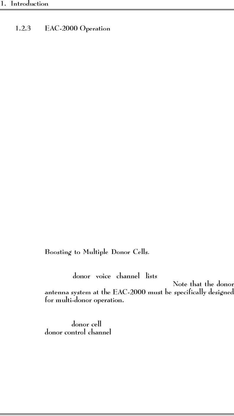
To provide for situations in
which in-progress calls may be linked to various neighboring cell
sites (multi-donor operation), the system allows for entry of three
separate , one for each possible
Supervisory Access Tone (SAT) frequency.
If the booster is adjacent to a single cell site, that cell site is referred
to as the , and the control channel of that cell site is the
. The voice channels used in the donor cell
may be entered into the donor voice channel list with the SAT of that
cell site to handle mobiles that drive between the donor and booster
with a call up.
Page 1-6 AMPS EAC-2000™ Manual: Vol. 1, Installation Procedures (27-7655-2, 12/95)
(Continued)
If the booster is adjacent to several cell sites and there are donor
antennas pointing at these cell sites, the control channel of one of the
cell sites is chosen as the donor control channel, and this cell is then
referred to as the . The voice channels of all the
neighboring cells are entered into the scan list with the SAT of the
neighboring cells.
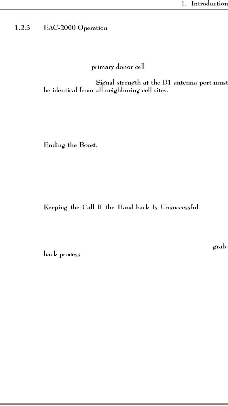
Calls placed or answered from within the booster coverage area
(identified by decoding the data streams) are boosted back to the
primary donor cell. Calls handed in (identified by channel scanning)
are boosted back to the cell on which the call was in progress.
The EAC-2000 monitors for SAT fade, weak
mobile RSSI, or mobile release to determine when to hand back the
mobile or terminate the translation through the booster. If weak RSSI
is detected, the EAC-2000 then sends the mobile a hand-off message
directing it back to the original donor voice channel. This allows the
mobile to be covered as it drives out of the booster coverage area
back into the donor cell site coverage area.
When a
mobile is heading away from the booster coverage area, it should be
handed back to the donor cell site only if there is a strong enough
signal to support the transmission. If the mobile is heading away
from the donor cell, handing it back to that cell would result in a
weak signal. To handle this situation, the EAC-2000 uses the
.
Shortly after sending the hand-off message, the EAC-2000 tries to
grab the mobile back by sending it a second hand-off message
directing it back to the boosted voice channel. Since the mobile
responds to the strongest signal, it will ignore the grab-back message
if the signal from the donor is stronger. If the booster signal is
stronger, the mobile will come back to the booster voice channel. If
the mobile’s RSSI is weak, the EAC-2000 will periodically send
hand-back/grab-backs but continue to handle the mobile until the
signal level is unusable.
AMPS EAC-2000™ Manual: Vol. 1, Installation Procedures (27-7655-2, 12/95) Page 1-7
6HFWLRQ 3UHOLPLQDU\'HFLVLRQV
2.1 Introduction
Before the EAC-2000 can be installed, preliminary decisions must be made
about the following:
• Use of Multi-hop configuration
• Booster site
• Antenna placement
• Control and voice channels to be used
As an installer, you may be involved in some or all of these decisions. The
checklist in Figure 2-1 provides a brief overview of preparations to be made
prior to installing the EAC-2000.
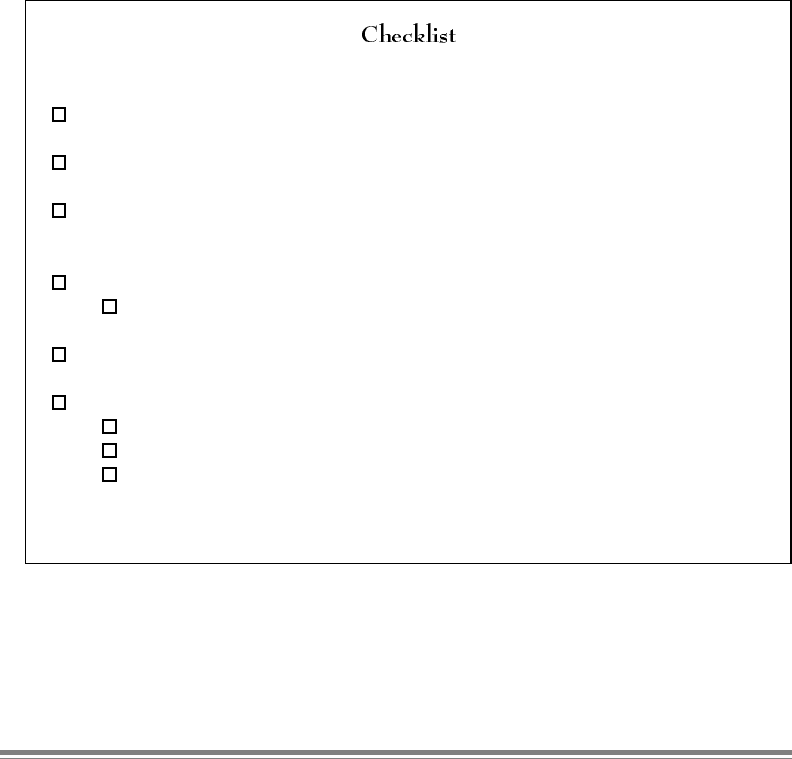
Figure 2-1. Pre-Installation Checklist
1. Coverage area and distance from base station identified. (Sec. 2.3.1)
2. Electrical service verified for installation site. (Sec. 2.3.2)
3. Site selected in accordance with EAC-2000 weight and space requirements.
(Secs. 2.3.3 and 2.3.4)
4. M1, M2, D1 and mobile modem antennas selected and installed. (Sec. 2.4)
Minimum vertical separation of antennas achieved.
5. Antenna isolation and signal levels from the cell site measured. (Sec. 2.4.3)
6. RF channels selected: (Sec. 2.5)
Donor control channel
Boosted control channel
Directed retry channels (at least one of the six directed retry channels should
be assigned)
AMPS EAC-2000™ Manual: Vol. 1, Installation Procedures (27-7655-2, 12/95) Page 2-1
2.2 Use of Multi-Hop™ Configuration or Multi-Donor™ Units
Multi-hop operation involves setting up two or more EAC-2000 units to operate
together in a line. This configuration is described in greater detail in Section 7.
Use of Multi-Donor Units involves placing a reverse-translating Multi-Donor
Unit at cell sites adjacent to the booster to allow mobiles to be handed-off to the
appropriate cells as they leave the booster area. Operation with Multi-Donor
Units is described in Section 8.
If either of these arrangements is to be used, system parameters will need to be
set accordingly. Minimum signal level requirements will also be affected.
2.3 Site Requirements
The site chosen for the EAC-2000 must meet requirements related to location,
electrical service, space, and mounting surface, as described below.
If a line-of-sight path between donor
cell and booster is maintained and a high-gain 6- to 10-foot (2- to 3-
meter) dish antenna is used, the EAC-2000 may be placed up to 80
miles (130 km) away from the donor cell. (Using frequency
translation for both voice and control channels makes it possible to
place the booster farther from the donor cell than is possible with
nontranslating boosters.)
The unit should be placed as close as
possible to the antennas to avoid excessive cable loss. Losses should
be kept to 3 dB or less for each antenna cable.
Page 2-2 AMPS EAC-2000™ Manual: Vol. 1, Installation Procedures (27-7655-2, 12/95)
The following ac service is required:
• 240 Vac
• single-phase
• 20-amp minimum service
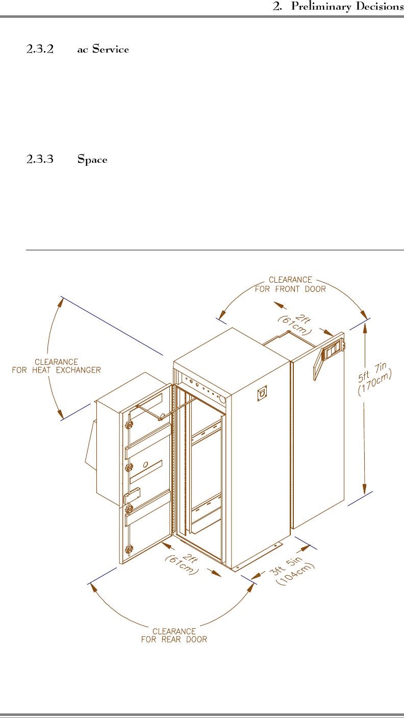
The EAC-2000 unit is approximately 2 ft (W) x 3 ft 5 in (D) x 5 ft
7 in (H) (61 cm x 104 cm x 170 cm). Allow space for the unit itself
plus additional space for access to the front and rear doors.
Figure 2-2. Recommended Space
AMPS EAC-2000™ Manual: Vol. 1, Installation Procedures (27-7655-2, 12/95) Page 2-3
The outdoor cabinet should be bolted to a concrete or other
weatherproof pad capable of supporting approximately 250 pounds
per square foot (1220 kg per square meter). Adequate drainage away
from the pad should be provided to prevent water from accumulating
underneath the cabinet.
2.4 Antennas
The EAC-2000 requires four antennas:
• Primary antenna facing donor cell site(s), used for—
- Reception of control and voice channel signals from donor cell
site(s).
- Transmission of control and voice signals back to cell site(s).
• Primary antenna facing mobiles in the booster coverage
area, used for—
- Transmission of boosted control channel and boosted voice channels
to mobiles.
- Diversity reception from mobiles.
- Transmission of hand-back messages to mobiles.
• Second antenna facing mobiles in the booster coverage area,
used for—
- Sending hand-in and grab-back messages to mobiles.
- Diversity reception from mobiles.
- Sending data messages to multi-hop EAC-2000s and Multi-Donor
Units.
• Antenna for the installed cellular mobile. Used for—
- Receiving and transmitting signals from any cell site in the system.
Ensure that the proper antenna type and placement have been selected for each
antenna.
Page 2-4 AMPS EAC-2000™ Manual: Vol. 1, Installation Procedures (27-7655-2, 12/95)

The antennas for the booster area should be chosen by the same
criteria as used for a cell site. A typical installation might use the
following antennas:
• One high-gain directional antenna pointed toward the
donor cell.
• and Two identical directional or omnidirectional
antennas.
A directional antenna facing away from the donor's coverage
area is recommended for installations where the booster is
located near the edge of the donor cell's coverage area. This
arrangement prevents the unnecessary boosting of mobiles that
are in the donor cell's primary coverage area. It also allows
fewer channels of equipment to be used at the booster location.
Omnidirectional antennas are appropriate for most other
applications.
Regardless of the type of antenna chosen, the
M1 and M2 antennas must have identical gain and
patterns, and be installed to cover the same area.
• A low-gain or YAGI base station antenna.
AMPS EAC-2000™ Manual: Vol. 1, Installation Procedures (27-7655-2, 12/95) Page 2-5
Antenna locations must meet the following
requirements for minimum signal level, physical separation, and
isolation.
• The minimum signal level from any
cell to be used as a donor must be -75 dBm at the D1 antenna
connector on the EAC-2000. The minimum signal level from
the donor cell must be at least -105 dBm at the mobile antenna
feed.
Multi-hop configurations: An EAC-2000 not adjacent to the
donor requires a forward signal level of at least -70 dBm (at the
D1 antenna connector) from the previous EAC-2000 in the chain.
Each booster along the path must be able to communicate only
with the previous and next booster. They are not required to be
able to receive from or transmit back to the donor cell site.
Multi-Donor Units: The RF path between the M2 antenna and
the Multi-Donor Unit "booster link antenna" must be such that
the Multi-Donor Units can receive at least a -100 dBm signal
when the EAC-2000 transmits using PA 6.
• For diversity operation, the M1 and M2
antennas should be physically separated by 10 feet (3 m)
horizontally or 3 feet (1 m) vertically.
Even if diversity reception is not required, both
the M1 and M2 antennas must be installed, since both
antennas are used to transmit to the boosted mobiles.
Page 2-6 AMPS EAC-2000™ Manual: Vol. 1, Installation Procedures (27-7655-2, 12/95)
(Continued)
• Isolation between the D1 and M1 and between the
D1 and M2 antennas . Isolation
between the mobile antenna and all of the others
.
Figure 2-3 shows a typical installation. M1 and M2 are placed
highest on the tower to achieve the best coverage to the boosted
area. D1 is placed below M1 and M2. At least 50 feet (15 m)
of vertical separation is usually needed to meet the isolation
requirement.
The isolation achieved at a given separation will
vary greatly depending upon the type of antennas, nearby
reflections, etc. Fifty feet (15 m) vertical separation may
not be enough in all cases.
D1 must be placed high enough to receive the required
minimum signal level from the donor. The mobile antenna can
usually be placed close to the ground. At least 35 feet (11 m)
vertical separation between the mobile antenna and the others is
usually needed, however, more may be required in some
installations.
AMPS EAC-2000™ Manual: Vol. 1, Installation Procedures (27-7655-2, 12/95) Page 2-7
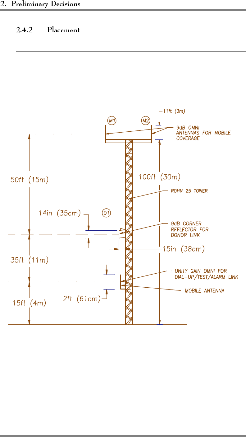
(Continued)
Figure 2-3. Typical Antenna Installation
Page 2-8 AMPS EAC-2000™ Manual: Vol. 1, Installation Procedures (27-7655-2, 12/95)

To verify the correct placement and alignment of the antennas, it will
be necessary to measure the signal level from the donor cell site (on
the selected donor control channel) and the isolation between the
various antennas to ensure they meet the required levels.
To measure the donor control channel signal level—
• connect a communications service monitor or some other
frequency selective measuring instrument to the D1 antenna;
monitor the control channel from the donor cell;
• adjust the orientation of the D1 antenna to peak this reading; at
least -75 dBm is required.
To measure antenna isolation—
Antenna isolation can be measured using a spectrum analyzer and a
tracking generator. These functions are often combined in cellular
communications monitors.
The tracking generator output is applied to the coax connector going
to one of the system antennas, while the spectrum analyzer input is
connected to one of the other system antennas. The tracking
generator output level should be set to maximum (usually about 0
dBm), with the spectrum analyzer set to check both the transmit and
receive ends of the band. If a 0 dBm signal is used as the source, the
dBm reading on the analyzer will be equal to the amount of isolation
achieved between the two antennas.
Isolation is usually frequency dependent, with several
nulls and peaks possible in each band. The highest peak in
either band defines the minimum isolation that is achieved with
a particular antenna installation.
AMPS EAC-2000™ Manual: Vol. 1, Installation Procedures (27-7655-2, 12/95) Page 2-9
(Continued)
Signals from the cellular system will likely be stronger than the
sweep signal received from the tracking generator, and difficulty may
be experienced in measuring the actual isolation.
Many spectrum analyzers have difficulty reading signals below -60
to -70 dBm when sweeping a broad bandwidth. In this case, the
band may be swept in smaller frequency segments, or a separate
signal generator with higher possible output power may be substituted
for the tracking generator. The signal generator frequency and
amplitude can be manually changed to avoid conflict with existing
strong signals from the donor and other cell sites.
The signal generator should be manually swept through both the low
split and the high split bands to determine the minimum isolation
point.
To measure isolation—
1. Supply a known signal level of about 0 to +20 dBm across the
band into one of the antenna feeds (M1, D1, or mobile).
2. Using test equipment, measure the signal level received on the
other antenna feeds.
3. Adjust antenna locations and orientations to achieve the desired
antenna isolations.
4. Move the signal source to other antennas, and recheck the
isolation. Be sure to check both the forward and the reverse
bands.
5. If the D1 antenna has been repositioned, recheck the received
donor control channel signal level to verify that it exceeds -75
dBm.
6. Record these measurements.
Refer to Appendix B for a more detailed procedure for measuring
isolation.
Page 2-10 AMPS EAC-2000™ Manual: Vol. 1, Installation Procedures (27-7655-2, 12/95)
2.5 Selecting Channels
Before beginning to install the hardware, identify the various channels on which
the system will operate:
• Donor control channel
• Boosted control channel
• Substitute control channel (if Revertive Control Channel Option is enabled)
• Donor voice channels (primary and neighboring)
• Boosted voice channels
• Directed retry channels
Make note of all selected channels. They will be entered as system parameters
during installation (Volume 1, Section 4). Control channel parameters are listed
under the Control Channels Menu, shown here with all available selections.
Refer to this menu for sections 2.5.1 through 2.5.5.
A Donor Control Channel ...................................... 337
B Boosted Control Channel .................................... 340
C RF Board to Use for Control Channel ............................. 1
D Control Channel State During "All Channels Busy" ...... DIRECTED RETRY
E Directed Retry Channels .................................... LIST
F Back-up Control Channel Option ......................... DISABLED
G Revertive Control Channel Option ........................ DISABLED
H Substitute Control Channel ............................. DISABLED
I Booster Link Channel....................................... 550
J Booster Link Channel - Previous EAC ........................... 571
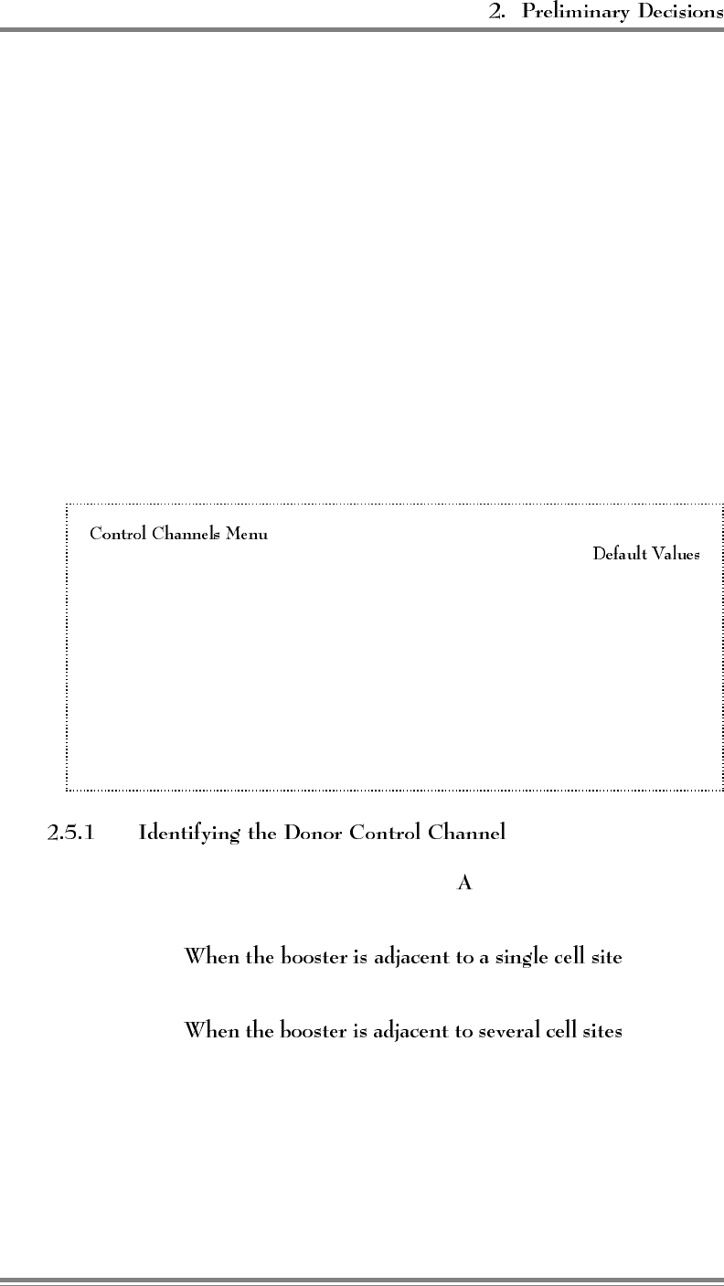
The donor control channel (selection ) is the control channel of the
primary cell site with which the EAC-2000 will communicate.
•, the control
channel of that cell site is the donor control channel.
•, the control
channel of the cell site with the most unused channels should be
chosen. (This cell is then referred to as the primary donor cell.)
More than one cell site being received by a donor antenna can
result in unwanted hand-offs by the cellular system, causing
dropped calls.
AMPS EAC-2000™ Manual: Vol. 1, Installation Procedures (27-7655-2, 12/95) Page 2-11
The boosted control channel (selection ) is the control channel that
will be used in the EAC-2000 coverage area. Select a channel that
meets the following requirements:
• Must be one of the dedicated control channels:
– System A = channels 313–333
– System B = channels 334–354
• Must be different from the control channels used in cells
adjacent to the booster to avoid interference.
There must be at least a 3-channel spacing between any
boosted channel and any donor channel.
When the Revertive Control Channel Option (selection G) is enabled,
the EAC-2000 continues to repeat the control channel (forward and
reverse) when all of the normal voice channels become occupied. If
another call goes through, the control channel equipment is
redesignated to operate as voice, and the last candidate is assigned to
and boosted by the control channel equipment.
Because of the fixed-tuned combiner used in the forward direction,
the mobile operates in voice mode on the boosted control channel.
The EAC-2000 translates the boosted control channel to the originally
assigned donor voice channel. The donor side of the EAC-2000
channels is not fixed in frequency.
When the call on the control channel ends, the equipment reverts to
repeating the control channel. If a call on one of the normal voice
channels ends, the EAC-2000 hands-off the mobile operating on the
control channel equipment to the available voice channel equipment
(this is referred to as ). The control channel equipment
then reverts to repeating the control channel.
Page 2-12 AMPS EAC-2000™ Manual: Vol. 1, Installation Procedures (27-7655-2, 12/95)
If the Revertive Control Channel Option is enabled, the Substitute
Control Channel parameter (selection ) will appear.
This parameter may be enabled to keep mobiles not in a call from
roaming during times when the control channel equipment is being
used to boost a voice call. The EAC-2000 uses channel 6 equipment
(the only RF elements not involved in boosting a voice call) to put
the substitute control channel on the air.
The Substitute Control Channel parameter may be disabled. In this
case, the Revertive Control Channel option will still operate. That is,
calls will be handled by the control channel equipment and
transferred to voice channel equipment when it becomes available.
However, during this time no control channel will be transmitted in
the booster coverage area.
This selection would be appropriate if there is sufficient control
channel coverage from other cells throughout the majority of the
booster coverage area, or if it is permissible to allow mobiles to
roam.
If substitute control channel transmission is desired, a channel must
be chosen and entered. Choose a channel that meets the following
criteria:
• Separated from the boosted control channel by at least 90 kHz.
(This prevents interference. There is no advantage to greater
separation.)
• Different from the donor control channel, and separated from it
by at least 90 kHz.
• Different from the control channels of other cells that may
provide coverage in the booster coverage area.
AMPS EAC-2000™ Manual: Vol. 1, Installation Procedures (27-7655-2, 12/95) Page 2-13
The directed retry channels parameter (selection ) is probably the
best option for most EAC-2000 installations. The parameter is a
factory-set default and is one of five options available under selection
(Control Channel State During "All Channels Busy") of the
Control Channels Menu.
When the EAC-2000 is busy, the boosted control channel (or
substitute control channel, if Revertive Control Channel Option is
enabled) remains on the air. If more accesses or page responses
come in, the EAC-2000 sends the mobile a special "directed retry"
message. This message gives the mobile a list of up to six other
control channels on which to attempt the access. These are the
and are assigned by the customer.
The list of six channels is sent to the mobile in the directed retry
message. The mobile will scan this set of channels and try its access
on the strongest of the six channels.
The donor control channel and the control channel of
cells adjacent to the boosted coverage area should be entered.
The boosted control channel must not be in this list.
Page 2-14 AMPS EAC-2000™ Manual: Vol. 1, Installation Procedures (27-7655-2, 12/95)
The donor and boosted voice channels can be accessed from the
Voice Channels Menu, shown here with all available selections.
Refer to this menu for sections 2.5.5 and 2.5.6.
A Donor Voice Channels (5970 Hz SAT) .................. List
B Donor Voice Channels (6000 Hz SAT) .................. List
C Donor Voice Channels (6030 Hz SAT) .................. List
M Donor Voice Channels (MULTIPLE SAT) ................ List
2 Boosted Voice Channel Position 2 ...................... 361
3 Boosted Voice Channel Position 3 ...................... 382
4 Boosted Voice Channel Position 4 ...................... 403
5 Boosted Voice Channel Position 5 ...................... 424
7 Boosted Voice Channel Position 7 ...................... 445
8 Boosted Voice Channel Position 8 ...................... 466
9 Boosted Voice Channel Position 9 ...................... 487
10 Boosted Voice Channel Position 10 ..................... 508
11 Boosted Voice Channel Position 11 ..................... 529
The EAC-2000 allows three lists of donor voice channels to be
entered, one for each possible SAT frequency. The lists are used to
identify mobiles that may drive into the booster coverage area with
a call already in progress (that is, already on a voice channel). The
EAC-2000 scans the donor voice channels on the lists, looking for
RSSI above a preset hand-in threshold.
AMPS EAC-2000™ Manual: Vol. 1, Installation Procedures (27-7655-2, 12/95) Page 2-15
(Continued)
Identify the donor voice channels with the following guidelines in
mind:
• All voice channels of the primary donor cell will be entered in
the donor voice channel list with the SAT of the primary donor
cell.
• The voice channels of neighboring cells will not be entered into
the donor voice channel lists with the SATs of the neighboring
cells unless the EAC-2000 donor antenna system has been
configured for multi-donor operation.
• For a donor cell site to be included in the donor voice channel
list, the signal level at the booster from that donor cell site must
be the same as the primary donor. If the antenna installation is
such that this criterion is not met for one of the neighboring cell
sites, that cell's voice channels should not be entered in the list.
You must select channels for the boosted voice channels. Note that
the number of boosted voice channels is almost always smaller than
the number of channels on the donor voice channel lists. For
example, the primary donor cell may have 15 voice channels, and the
EAC-2000 may have 9 voice channels.
Select an unused channel for each channel of equipment that is
installed in the EAC-2000, according to the following guidelines:
• Select the boosted voice channels in the same manner as for a
cell site.
• Consider channel reuse in the system when assigning the
boosted control and voice channels.
• Be sure the channels are spaced at least 600 kHz apart to allow
the combiner to operate properly.
• Be sure there is at least a 90 kHz separation between any
boosted and any donor channel.
Page 2-16 AMPS EAC-2000™ Manual: Vol. 1, Installation Procedures (27-7655-2, 12/95)
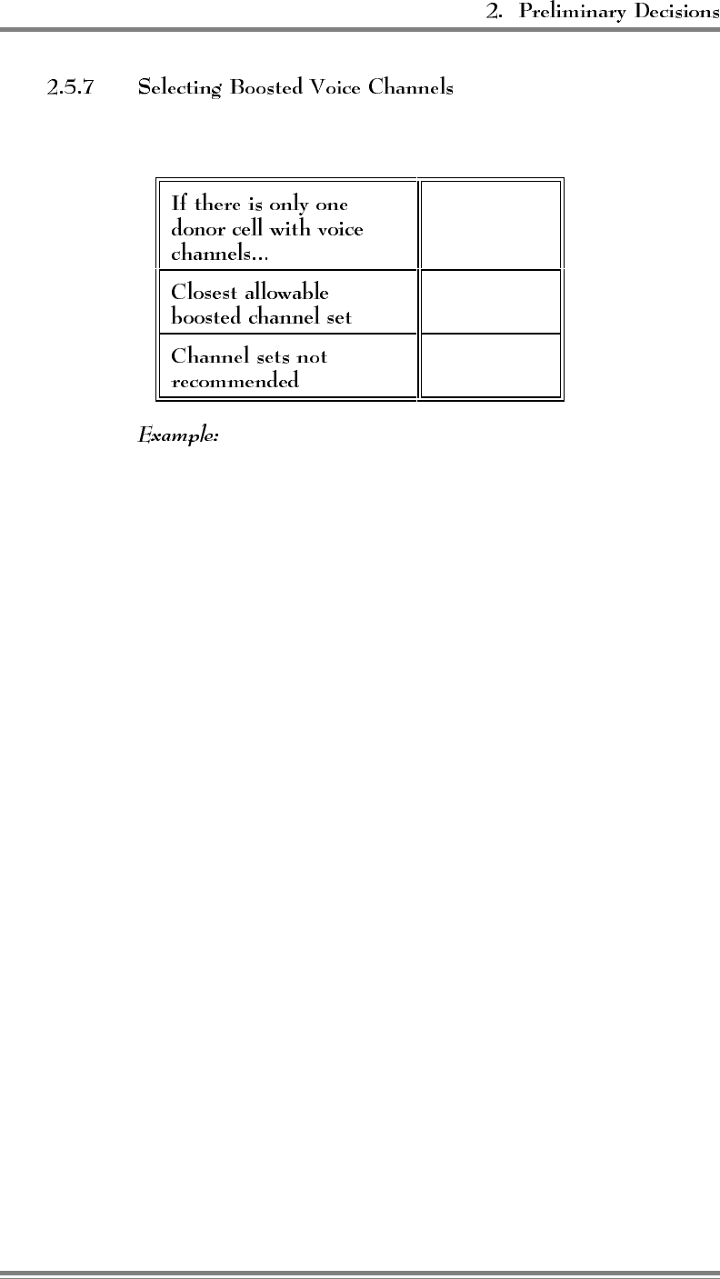
(Continued)
The following table illustrates proper channel separation:
1, 22, 43...
4, 25, 47...
2, 23...
3, 24...
If there is only one donor cell and it uses voice channels 1, 22, 43...,
then the closest spaced channel set that could be used for boosted
voice channels would be 4, 25, 47.... The channel sets 2, 23... and
3, 24... could not be chosen because they are too close.
AMPS EAC-2000™ Manual: Vol. 1, Installation Procedures (27-7655-2, 12/95) Page 2-17

6HFWLRQ ,QVWDOOLQJWKH+DUGZDUH
3.1 Introduction
This section provides instructions for—
• Mechanical installation
• Connecting ac power
• Installing the antennas
• Connecting external alarms/controls (optional)
The checklist in Figure 3-1 presents a brief overview of these installation
procedures. For more detailed descriptions of the procedures, refer to Sections
3.2–3.5.
Figures 3-2 and 3-3 show front and back views of the EAC-2000 with the doors
removed.
Figure 3-1. Hardware Installation Checklist
1. EAC-2000 uncrated and contents checked. (Sec. 3.2.1)
2. Holes drilled in pad (if using expandable anchors). (Sec 3.2.2)
3. EAC-2000 positioned, using lifting equipment, and bolted in place. (Sec.
3.2.2)
4. With ac service breaker and all EAC-2000 switches and breakers off, ac
electrical connections made. (Sec. 3.3)
• Green to ground
• White to neutral
• Black to 240 Vac (one side of ac service)
• Red to 240 Vac (other side of ac service)
5. Antennas connected; signal level and isolation measured/adjusted. (Sec. 3.4)
6. External alarms/controls connected, if required. (Sec. 3.5)
AMPS EAC-2000™ Manual: Vol. 1, Installation Procedures (27-7655-2, 12/95) Page 3-1
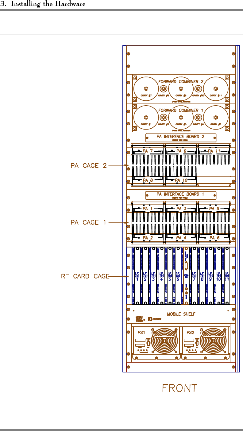
Figure 3-2. EAC-2000, Front View (Door Removed)
Page 3-2 AMPS EAC-2000™ Manual: Vol. 1, Installation Procedures (27-7655-2, 12/95)
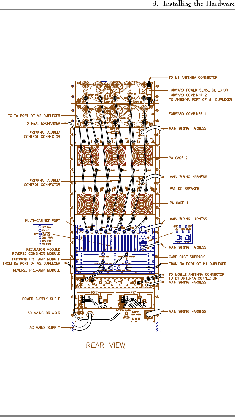
Figure 3-3. EAC-2000, Back View (Door Removed)
AMPS EAC-2000™ Manual: Vol. 1, Installation Procedures (27-7655-2, 12/95) Page 3-3
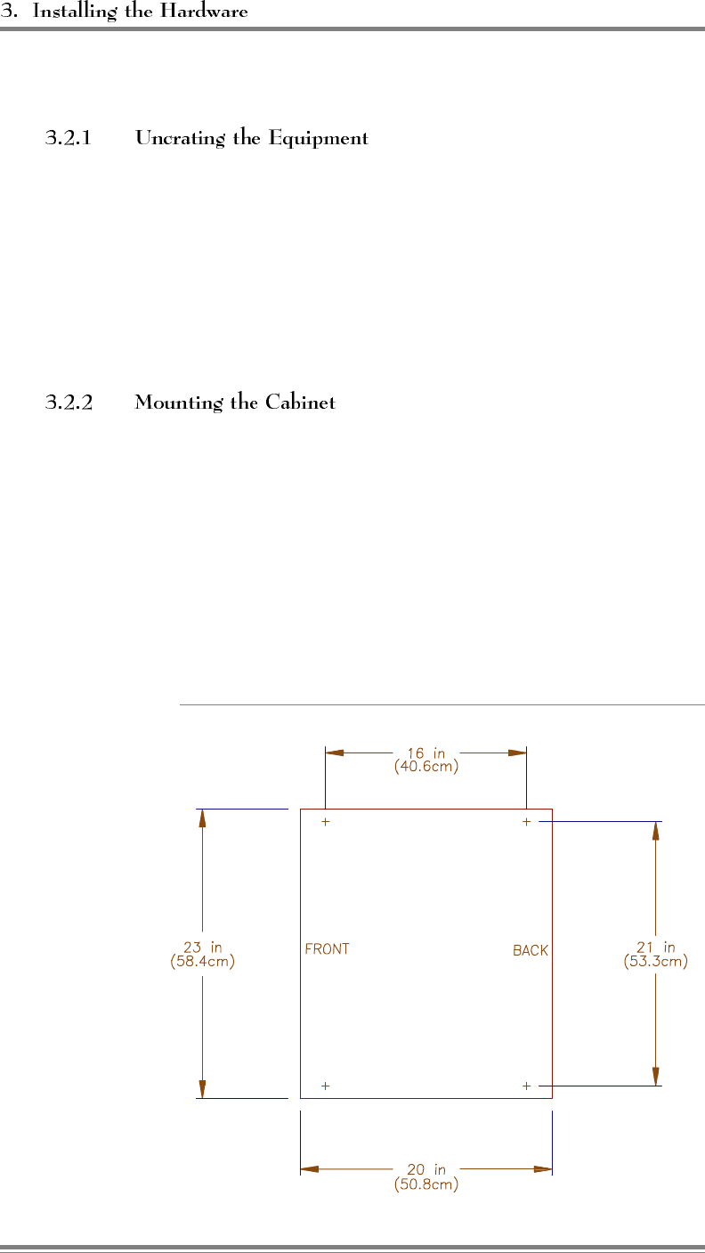
3.2 Mechanical Installation
The container includes these items:
• The EAC-2000 unit
• EAC-2000 manual (Volumes 1, 2, and 3), power supply manual,
mobile manual, and modem manual
Remove the shipping material from around the cabinet. Check the
contents and take care that no hardware or manuals are misplaced.
The mounting rails on the bottom of the cabinet provide clearance
space under the cabinet to allow moisture to evaporate. Four 5/8 in.
(16 mm) diameter holes are provided in the rails for bolting the
cabinet to the pad. The preferred mounting method is to drill holes
in the pad and use expandable anchors. Alternatively, bolts can be
cast into the concrete. Mount the cabinet to the pad as follows:
1. If using expandable anchors, determine the bolt locations (see
Figure 3-4) and drill holes in the pad.
Figure 3-4. Outdoor Cabinet Footprint
Page 3-4 AMPS EAC-2000™ Manual: Vol. 1, Installation Procedures (27-7655-2, 12/95)

(Continued)
2. Place the cabinet on the pad where it will be installed.
The EAC-2000 weighs almost
900 pounds (408 kg)! Use lifting equipment
to position the unit. Lifting rings on the
cabinet are provided for this purpose.
3. Bolt the cabinet to the pad.
Later, after all installation steps have been completed (including
electrical connections and initial system operation), secure the doors
as follows:
1. Close the cabinet door.
2. Secure the door with a lock to prevent unauthorized access.
3.3 Connecting the EAC-2000 to ac Power
To connect the EAC-2000 to the ac mains, make the following connections:
• Green wire to ground
• White wire to neutral
• Red and black wires to 240 Vac service
AMPS EAC-2000™ Manual: Vol. 1, Installation Procedures (27-7655-2, 12/95) Page 3-5
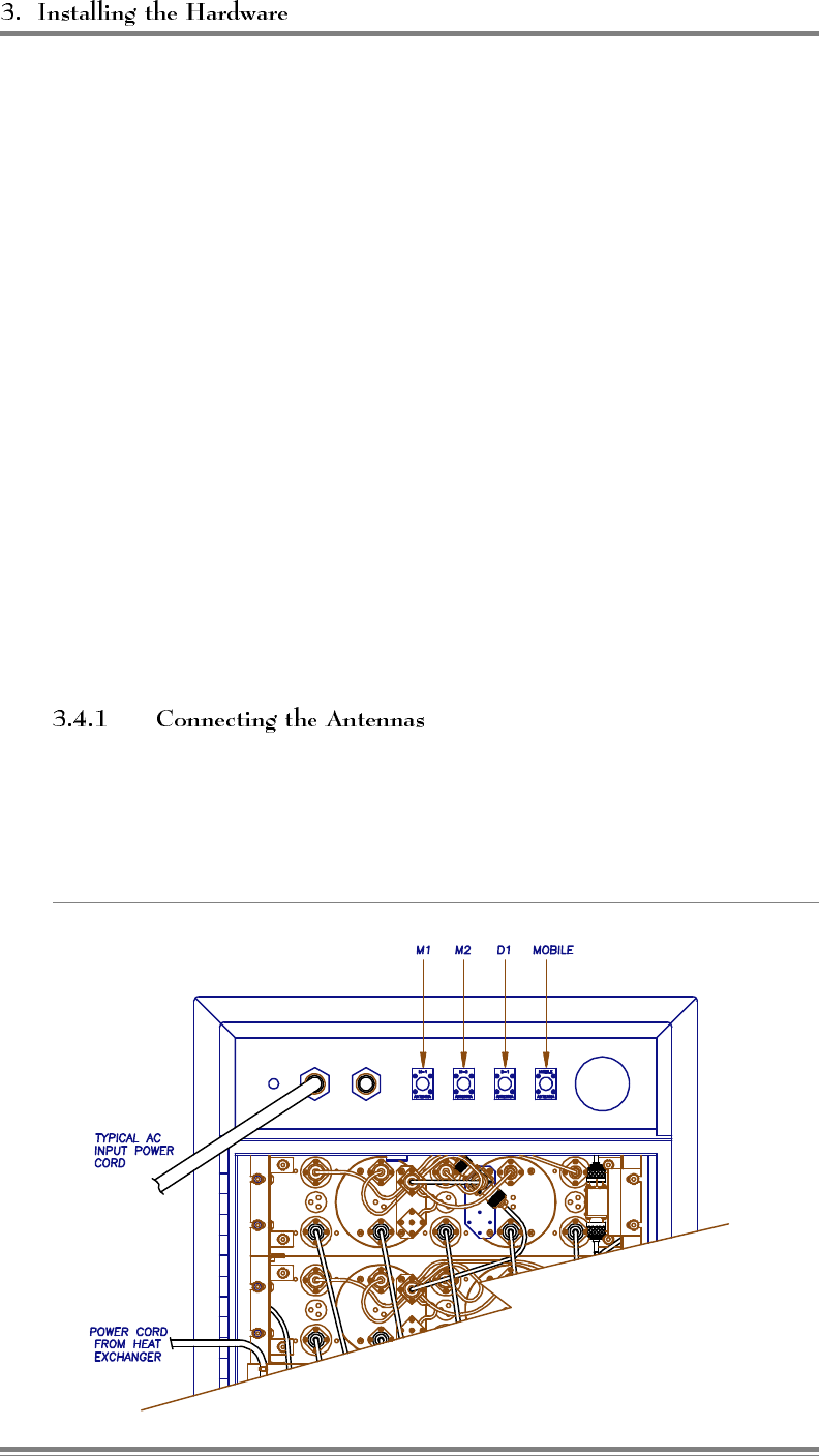
3.4 Installing the Antennas
Antennas should already have been mounted, as described in Section 2.4.2, in
locations that meet the following requirements:
• Minimum signal level from any donor cell: -75 dBm or greater at the D1
antenna connector. (See Section 2.4.2 for multi-hop and multi-donor unit
variations.)
• Physical separation: M1 and M2 antennas separated at least 10 feet (3 m)
horizontally or 3 feet (1 m) vertically (if diversity receive is desired).
• Isolation between D1 and M1, and between D1 and M2:
- > 75 dB
• Modem antenna: Placed so as to minimize interference with the M1, M2,
and D1 antennas (minimum 60 dB isolation required). The minimum
signal level required for proper operation is -105 dBm.
Antenna installation involves connecting the antennas to the EAC-2000,
measuring isolation and signal level, and making needed adjustments.
Connect the antennas to the EAC-2000. All antenna connectors (type
N) are located on the top rear of the cabinet, arranged as shown in
Figure 3-5.
Figure 3-5. Antenna Connectors
Page 3-6 AMPS EAC-2000™ Manual: Vol. 1, Installation Procedures (27-7655-2, 12/95)

3.5 Connecting External Alarms/Controls (Optional)
The EAC-2000 includes the following inputs and outputs, which may be used
to monitor or control non-EAC-2000 equipment:
• 4 digital inputs per PA cage
• 4 open collector digital outputs per PA cage
• 4 analog inputs per PA cage
• 1 +5 Vdc/100 mA source for powering external circuitry per PA cage
These inputs and outputs are located on the back of the PA cages on DB-25
female connectors. The pin designations are shown in Figure 3-6. The signals
on the pins are controlled and monitored via the local or remote link. Electrical
specifications for the pins are shown in Figure 3-7.
Figure 3-6. External Alarm/Control Connector Pin Out
Pin Function Pin Function
1+5 Vdc/100 mA 14 Ground
2Ext. Digital Output 4 15 Ground
3Ext. Digital Output 3 16 Ground
4Ext. Digital Output 2 17 Ground
5Ext. Digital Output 1 18 Ground
6Ext. Digital Input 4 19 Ground
7Ext. Digital Input 3 20 Ground
8Ext. Digital Input 2 21 Ground
9Ext. Digital Input 1 22 Ground
10 Ext. Analog Input 4 23 Ground
11 Ext. Analog Input 3 24 Ground
12 Ext. Analog Input 2 25 Ground
13 Ext. Analog Input 1
AMPS EAC-2000™ Manual: Vol. 1, Installation Procedures (27-7655-2, 12/95) Page 3-7

3.5 Connecting External Alarms/Control (Optional) (Continued)
Figure 3-7. Electrical Specifications for Inputs and Outputs
Pins Specifications
Digital Inputs (pins 6,7, 8, 9):
Load: > 100 kΩ
Low: < 2 Vdc
High: > 4 Vdc max. +28 Vdc
Open Collector Outputs (pins 2, 3, 4, 5): Max. +15 Vdc, 20 mA
Impedance 733 Ω
Analog input (pins 10, 11, 12, 13):
Load: 1 MΩ
Range: 0–5 Vdc, 20 mV resolution
+5 Vdc source (pin 1): +5 Vdc ±5%, 100 mA max.
The system designer should have identified any external alarms and controls to
be connected. Make external alarm/control connections as follows:
1. Identify the input/output connection to be used for each external
alarm/control that is to be installed. Figure 3-8 shows a typical wiring
diagram for external alarm input.
2. Make connections using a compatible male connector (not supplied).
Page 3-8 AMPS EAC-2000™ Manual: Vol. 1, Installation Procedures (27-7655-2, 12/95)
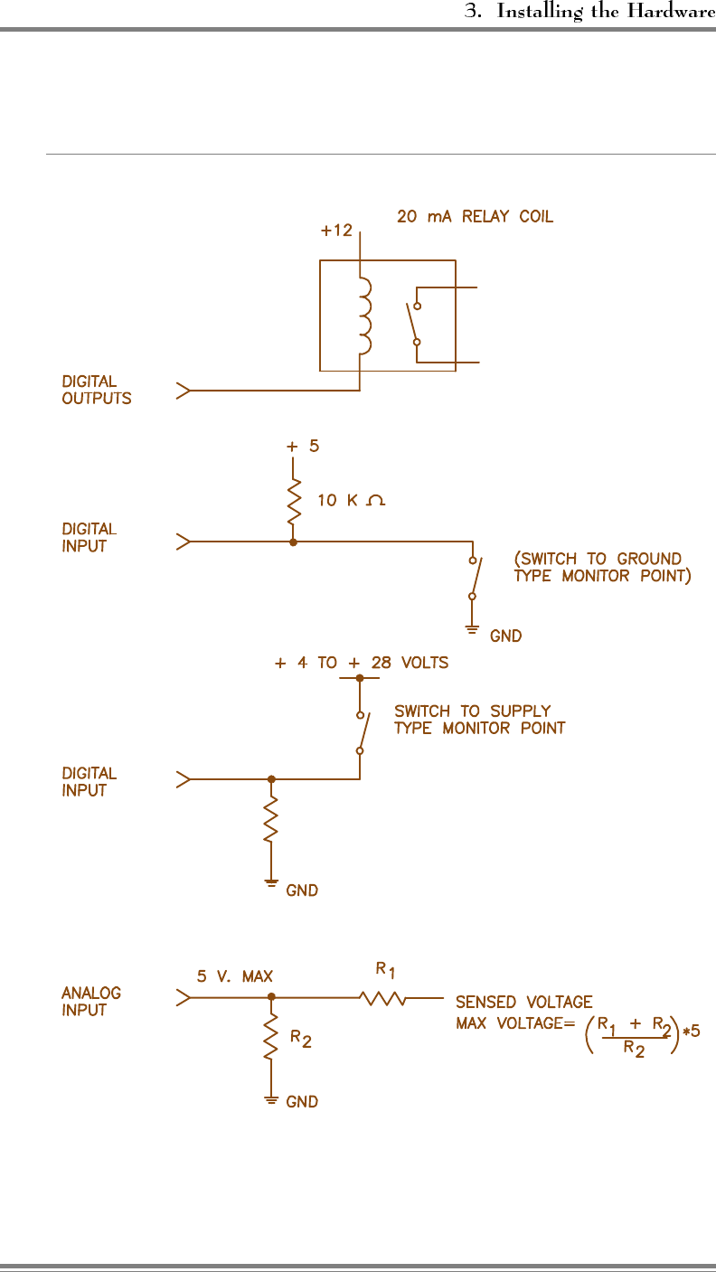
3.5 Connecting External Alarms/Control (Optional) (Continued)
Figure 3-8. Typical Wiring for External Alarm Input
AMPS EAC-2000™ Manual: Vol. 1, Installation Procedures (27-7655-2, 12/95) Page 3-9

6HFWLRQ 6HWWLQJ8SIRU,QLWLDO2SHUDWLRQ
4.1 Introduction
Most of the EAC-2000 operating parameters are under software control and can
be changed from either a local terminal or a remote terminal. You will probably
have to change some of these parameters to get the system running. After
programming channels, you will also need to tune the transmitter combiner and
adjust power levels.
This section describes procedures for—
• Powering up and powering down the EAC-2000
• Connecting the local terminal
• Becoming familiar with system commands
• Programming initial parameters
• Tuning the transmitter combiner and setting output power
The checklist in Figure 4-1 presents a brief overview of these procedures. For
more detailed descriptions of the procedures, refer to Sections 4.2–4.7. For
detailed descriptions of all parameters, refer to Volume 2, Operating Procedures.
Additional instructions for special EAC-2000 configurations and options are
provided in Sections 7 through 10. If you have problems during setup, refer to
Appendix A, Troubleshooting Guide.
AMPS EAC-2000™ Manual: Vol. 1, Installation Procedures (27-7655-2, 12/95) Page 4-1
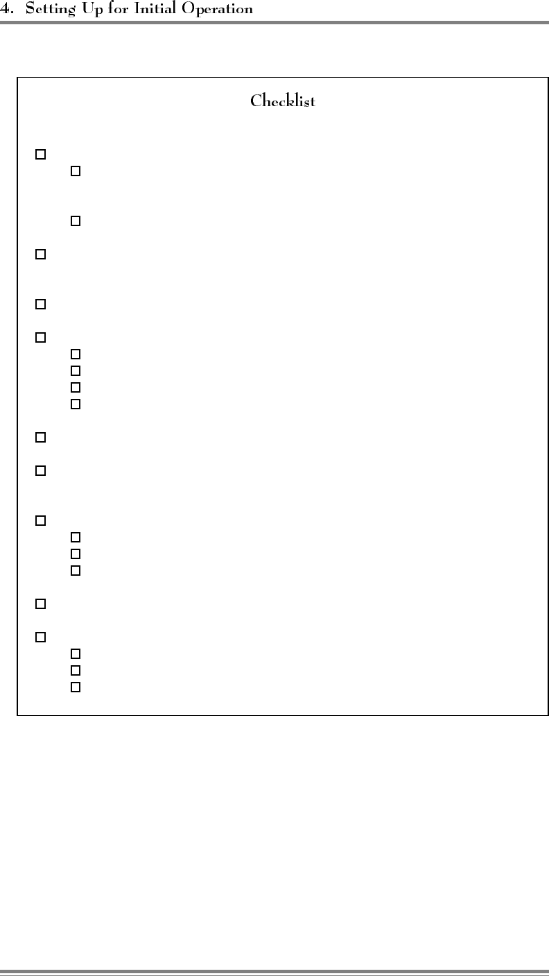
Figure 4-1. Setup Checklist
1. Local terminal connected: (Sec. 4.2 and 4.4)
a. Terminal powered up and set to 9600 baud, even parity, 7 data bits,
1 stop bit, full duplex, all capitals, send carriage return only, auto
XON/XOFF and soft scroll disabled.
b. EAC-2000 powered up and password entered.
2. System status (SSS) and alarm (ALA) report checked; no disabled and no
alarms shown. (Sec. 4.6.1)
3. Site ID entered. (Sec. 4.6.2)
4. RF Channels programmed:
a. Donor control channel programmed. (Sec. 4.6.3)
b. Boosted control channel programmed. (Sec. 4.6.4)
c. Donor voice channels entered in voice channel lists. (Sec. 4.6.5)
d. Boosted voice channels programmed. (Sec. 4.6.6)
5. Alarms and thresholds set (if desired). (Sec. 4.6.7)
6. Modem mobile MIN, mobile power step, and passwords programmed. (Sec.
4.6.8)
7. Transmitter combiner tuned and output power set:
a. PAs 1–5 and 7-11 (if installed) adjusted. (Sec. 4.7.1)
b. PA 6 adjusted. (Sec. 4.7.2)
c. Reverse path power level adjusted. (Sec. 4.7.3)
8. Clock set. (Sec. 4.7.4)
9. Call history, call statistics, and alarm report reset to 0: (Sec. 4.7.4)
a. DCH = 0 <CR>
b. DCS = 0 <CR>
c. ALA = 0 <CR>
Page 4-2 AMPS EAC-2000™ Manual: Vol. 1, Installation Procedures (27-7655-2, 12/95)

4.2 Powering Up the EAC-2000
Figure 4-2 lists the locations and functions of the EAC-2000 breakers. Figure
4-3 shows their locations.
Figure 4-2. EAC-2000 Breakers
Breaker Cabinet Location Controls
Main ac junction box ac service to entire cabinet
(lower left rear)
ac Breaker #1 28 Vdc power supply ac to power supply #1
(lower front)
ac Breaker #2 28 Vdc power supply ac to power supply #2
(lower front)
NOTE: Some configurations contain only one 28 Vdc power
supply.
PA dc Breakers Back of PA cage dc power to each PA
(one per PA)
Begin with all breakers off. To power up the system, switch on the breakers in
the following order:
1. Main ac breaker
2. ac breaker(s) (if both power supplies are installed, switch both on
simultaneously)
The PA dc breakers are provided to prevent wiring harness
damage in the event of catastrophic PA failure. These breakers cannot be
turned off manually. Refer to Appendix A, Section A.15.4, before
resetting a tripped PA dc breaker.
4.3 Powering Down the EAC-2000
To power down, switch off the breakers in the reverse order, as follows:
1. ac breakers
2. Main ac breaker (optional)
AMPS EAC-2000™ Manual: Vol. 1, Installation Procedures (27-7655-2, 12/95) Page 4-3
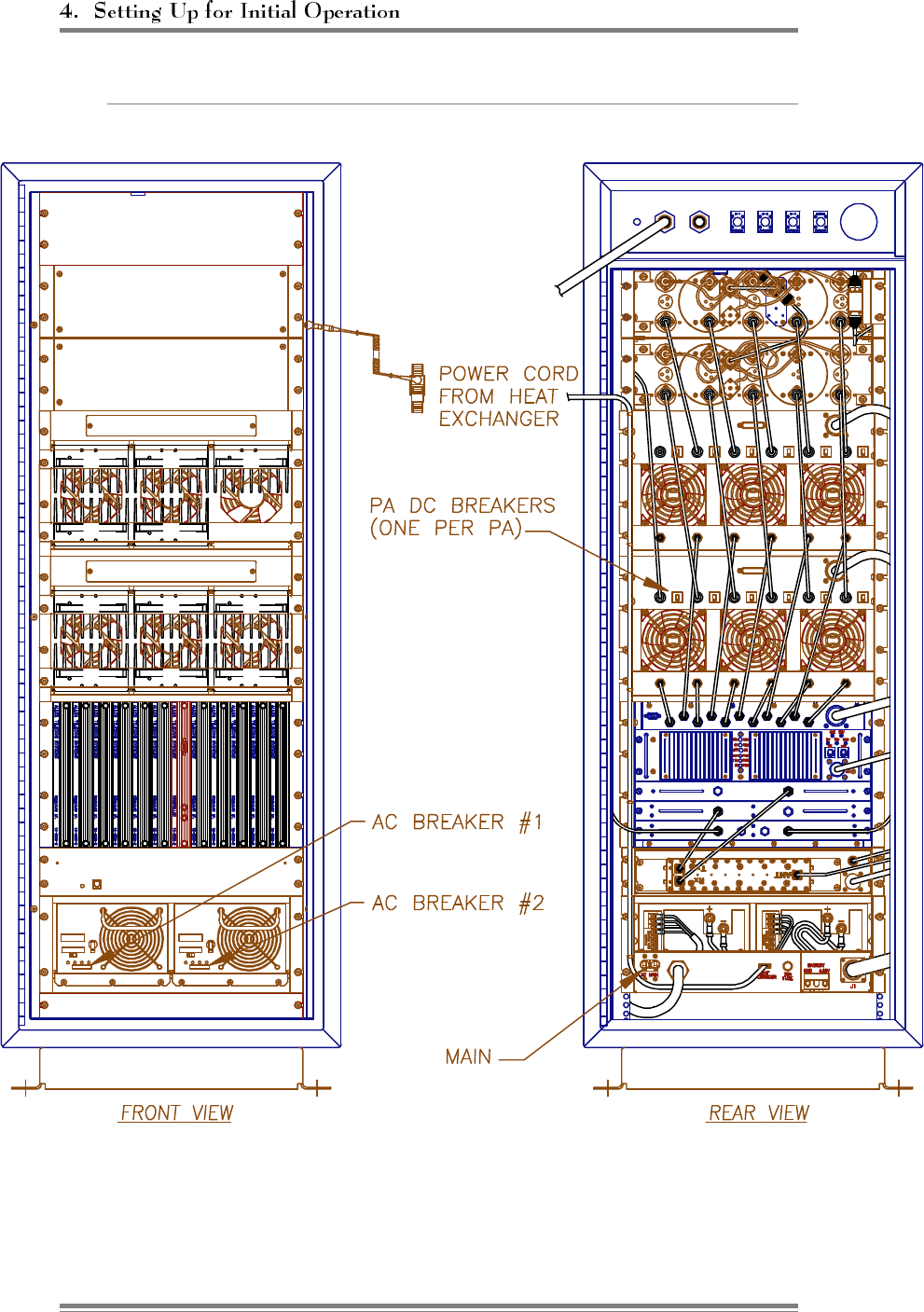
Figure 4-3. Breaker Locations
Page 4-4 AMPS EAC-2000™ Manual: Vol. 1, Installation Procedures (27-7655-2, 12/95)
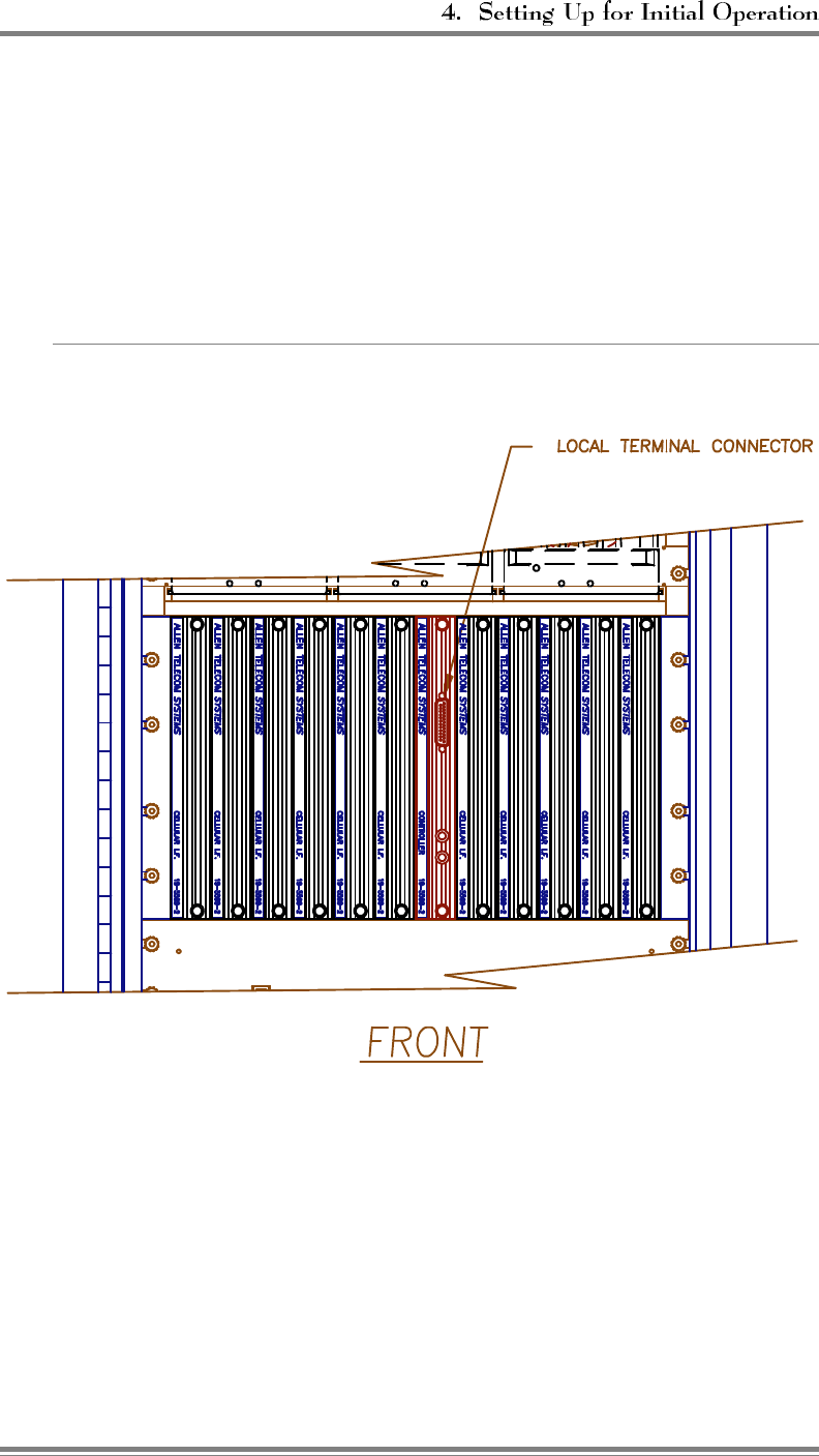
4.4 Connecting a Local Terminal
The EAC-2000 communicates with a conventional ASCII, RS232 terminal.
Connect the terminal as follows.
1. Using the cable provided in the tuck pack, connect the terminal to the 25-
pin D-sub connector located on the front of the controller module.
Figure 4-4. Location of Local Terminal Connector
AMPS EAC-2000™ Manual: Vol. 1, Installation Procedures (27-7655-2, 12/95) Page 4-5
4.4 Connecting a Local Terminal (Continued)
2. Power up the terminal and set it to the following parameters:
• 9600 baud
• Even parity
• 7 data bits, 1 stop bit
• Full duplex (no local echo)
If possible, also set the terminal to—
• All capitals
• Send carriage return only (no line feed)
• Disable AUTO XON/XOFF and soft scroll
If you are using a terminal emulation program, select TTY or VT100. Be
aware that some terminal emulation programs generate extraneous
characters that may interfere with communicating with the EAC-2000.
3. Power up the EAC-2000. (After about 2 seconds, the terminal should
respond CONSOLE LOCKED.)
4. Enter (carriage return or enter, depending on the keyboard). (The
terminal should respond with a welcome message and prompt you for a
password.)
• If something comes up but is illegible, check the terminal setup.
• If nothing comes up, power down. Recheck the power hookup, the
terminal hookup, and the terminal setup.
5. Enter the password, followed by . The default password is 1234.
(The terminal should respond with more salutation and the > prompt.)
The system is ready for you to set parameters.
Page 4-6 AMPS EAC-2000™ Manual: Vol. 1, Installation Procedures (27-7655-2, 12/95)
4.5 Becoming Familiar with System Commands
If you are new to EAC-2000 installation, you should use this section to gain
familiarity with basic rules for entering commands, as well as key commands
that will be used in setting up the system. If you are already familiar with the
system, turn to Section 4.6.
Figure 4-5 lists definitions of symbols and abbreviations that are used
in this section of the manual.
Figure 4-5. Command Definitions
Symbol/
Abbreviation Definition
>Command entry level. The system uses this prompt character
to indicate it is ready to accept commands.
<CR> Carriage return or enter.
<CTRL> Control. The control key is used in combination with other keys.
For example, <CTRL> Z means to hold down the control key
while pressing the Z key.
ESC Escape. Escape is a single key marked ESC on most keyboards.
The system responds to commands that consist of three
letters followed by up to three data fields, as follows:
In this syntax—
• COM is the particular three-letter command.
• FIELD 1 consists of up to four hex characters followed by a
hyphen (-).
• FIELD 2 consists of up to four hex characters followed by an
equals (=) sign.
• FIELD 3 consists of up to four hex characters.
• Each command ends with a carriage return (<CR>).
AMPS EAC-2000™ Manual: Vol. 1, Installation Procedures (27-7655-2, 12/95) Page 4-7
(Continued)
Very few commands entry of the
data fields. After the initial command has been entered, the system
usually prompts for data it needs. If a command does not depend on
a certain field, any data entered in that field will be ignored.
When entering commands—
• Spaces may be added to separate the fields, after the first three
letters have been entered.
• Leading zeros may be omitted.
• Use DELETE or BACKSPACE to correct mistakes.
• End the command with .
Figure 4-6 lists the commands you
are most likely to use. The most complex command is SET. This
command is structured to enable you to enter parameters easily and
accurately. The other commands, which are much simpler, require
little or no subsequent data input. Their action is complete in a
matter of seconds.
In an operational
system, SET may drop calls if certain parameters are changed.
RES will drop all calls currently being boosted. Otherwise, the
system commands do not interfere with call processing.
Some commands enter a
mode in which the program does something continuously. (These
commands are indicated by a dagger (†) in Figure 4-6.) To get out
of this mode and return to the command entry level, hit <ESC> or
type .
Entering or from the command
entry level (>) will cause the characters entered on the line to
be erased.
Page 4-8 AMPS EAC-2000™ Manual: Vol. 1, Installation Procedures (27-7655-2, 12/95)
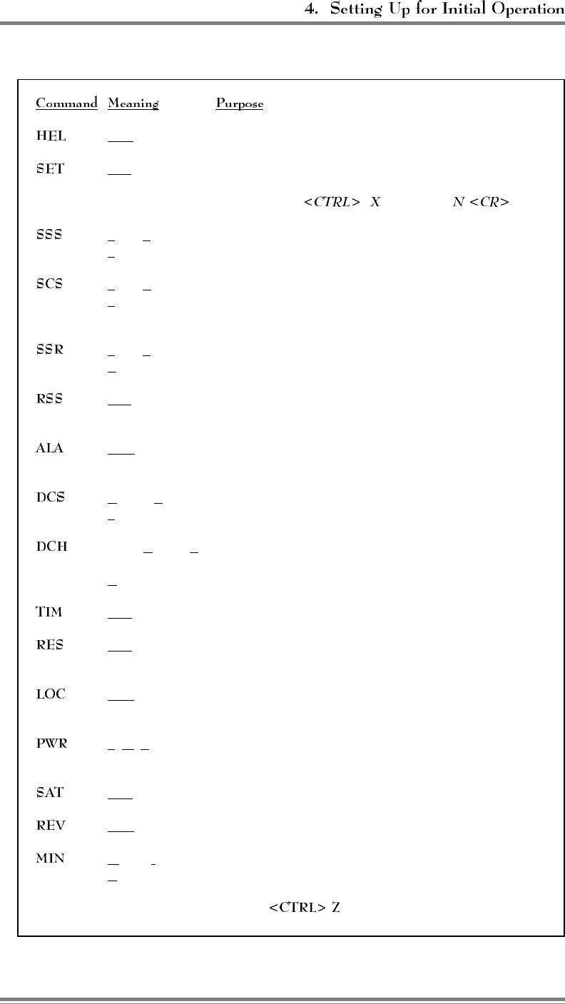
Figure 4-6. System Commands
HELp Gives a list of the primary commands.
SETup Invokes a menu-driven entry mode used to inspect or
change all EAC-2000 operating parameters. (To exit this
command, type and answer .)
Show System Gives a one-page listing of current EAC-2000 parameter
Status settings and conditions of monitored input parameters.
†Show Call Shows current status of each board. Updates listing if
Status status changes (e.g., if a call is set up or taken down) and
gives reason for change.
†Show Scanned Shows average RSSIs of channels being scanned.
RSSI
†RSSI Report Gives a continuously updated reading of RSSIs on all RF
boards.
ALArm Report Gives a report of the number of times various alarm
conditions have occurred since last system reset.
Display Call Displays various call statistics per board (totals since
Statistics last DCS=0 command).
Display Call Displays hourly totals of certain call statistics for
the
History last running week.
TIMe Displays/changes current clock time and date.
RESet Resets EAC-2000. Parameters in effect when command is
issued will be preserved.
LOCk Forces password entry before accepting subsequent
commands.
†PoWeR Repeatedly lists power readings on all installed PAs.
display
†SAT report Repeatedly lists the SAT readings on the boards.
REVision Displays hardware revisions in the EAC-2000.
†Mobile ID Lists the last five access attempts by mobiles.
Number
† To exit this command, hit ESC or type .
AMPS EAC-2000™ Manual: Vol. 1, Installation Procedures (27-7655-2, 12/95) Page 4-9
(Continued)
A session can be ended in three ways:
• This command should be used if the session
involves only system monitoring or minor parameter changes.
It ensures security, but lets alarms and call statistics continue to
accumulate.
• This command should be used if extensive
parameter changes have been made during a session. This
method—
- Ensures that all parameter changes take effect, since all
hardware is initialized after a reset.
- Ensures security because the password must be reentered
to get back to the command level.
- Initializes all alarm condition counters to 0.
• An inactivity timer is included in the
program with a default inactivity timeout setting of 5 minutes.
If a keyboard entry is not detected within the designated period,
the system terminates any currently running command (e.g.,
SET) and simulates the action of LOC. This avoids leaving the
EAC-2000 in an insecure state if the remote link is lost before
the session is properly ended.
If a remote terminal is linked by modem to the
EAC-2000, LOC, RES or timeout will terminate the link.
Page 4-10 AMPS EAC-2000™ Manual: Vol. 1, Installation Procedures (27-7655-2, 12/95)
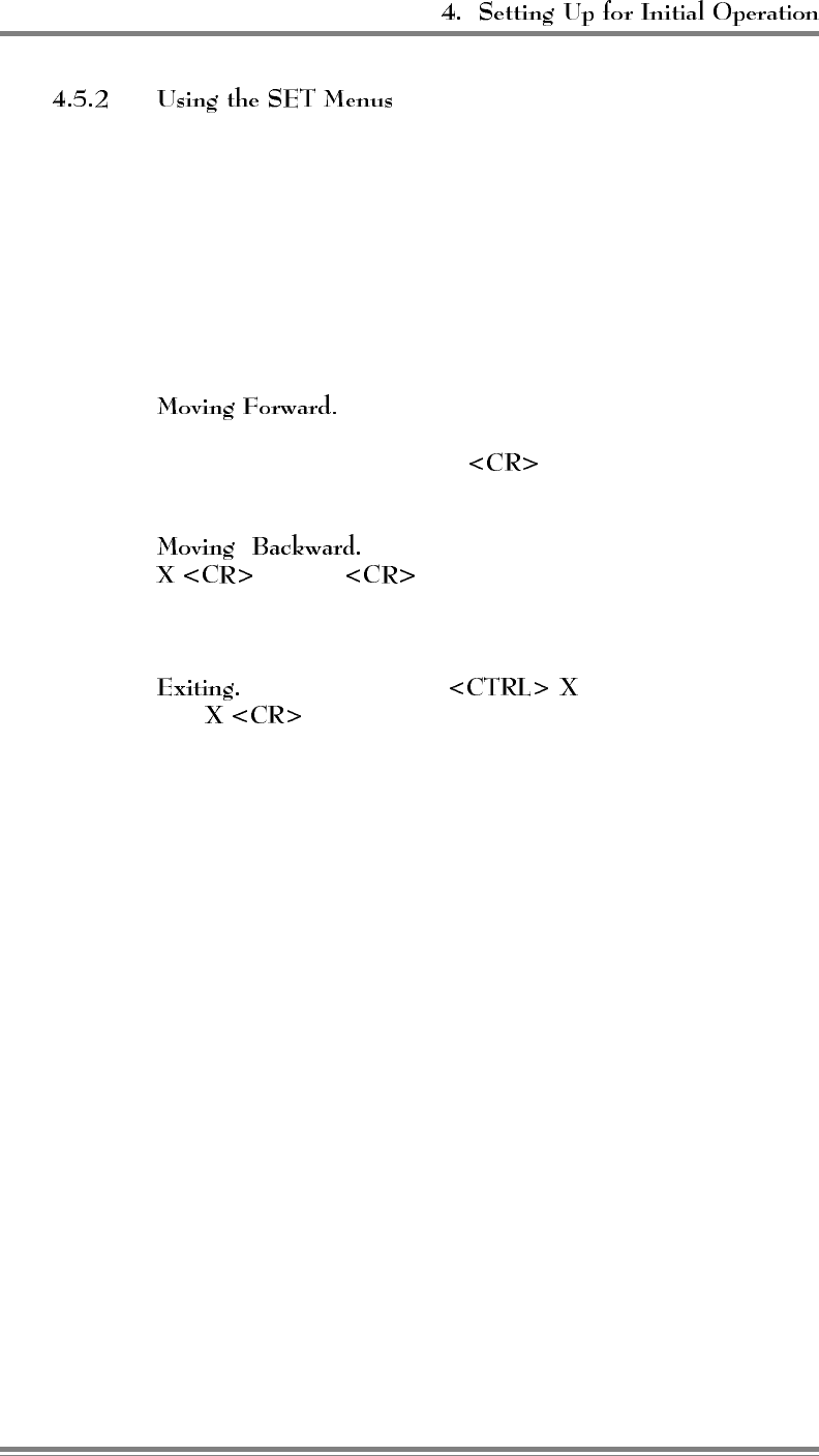
Configuring the EAC-2000 to fill in a coverage area in a specific
cellular system is easy, using either the local terminal or a remote
terminal. From the command entry level (>), the SET command
invokes the setup utility which displays a progression of menus. The
menus provide a guided path to each EAC-2000 parameter. Figure
4-7 illustrates the paths to follow through the SET menus to reach
each available parameter. For descriptions of all SET menus and
commands, see Volume 2, Operating Procedures.
Each command brings up a menu of items from
which to choose, with a character in front of each item. To select an
item, type the character and . The next menu (or the
parameter to be changed) will be displayed.
To move backward along a path, type
, or just . (Both entries correspond to the "Done
with this menu" selection.) The previous menu will be displayed.
Continue in this manner until you have the SET Main Menu.
To exit SET, type at any menu level. Or,
type while at the Main Menu level.
AMPS EAC-2000™ Manual: Vol. 1, Installation Procedures (27-7655-2, 12/95) Page 4-11
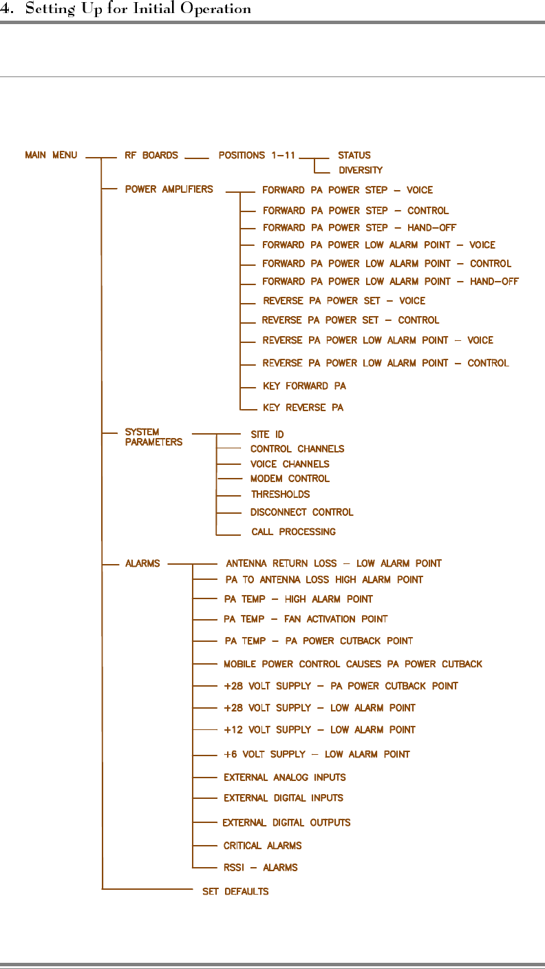
Figure 4-7. SET Command Menu Map
Page 4-12 AMPS EAC-2000™ Manual: Vol. 1, Installation Procedures (27-7655-2, 12/95)
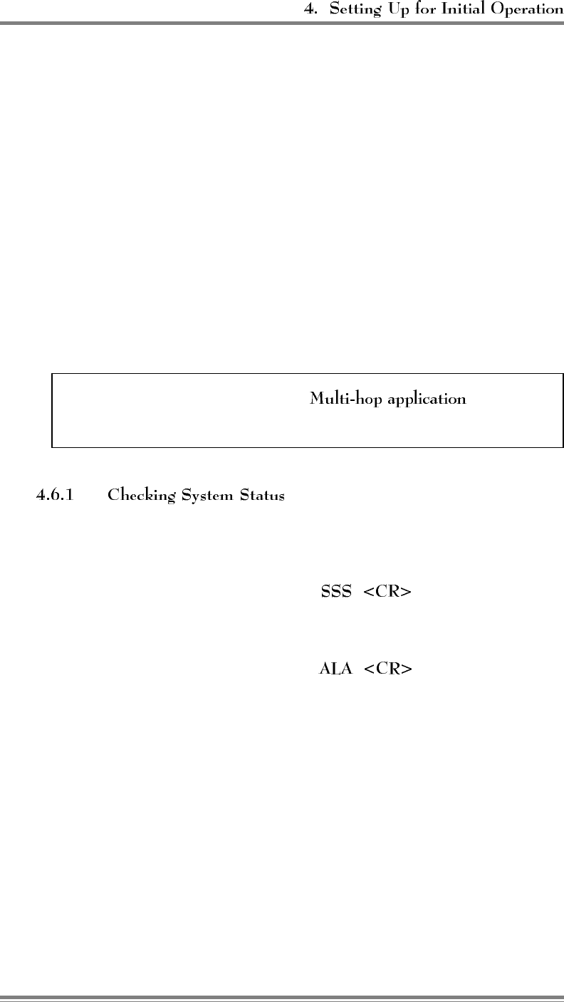
4.6 Setting Initial Parameters
Before you can operate the EAC-2000, you must check system status and
program the following:
• Site identification
• Donor control channel
• Boosted control channel
• Directed retry channels
• Donor voice channels
• Boosted voice channels
You should already have the list of selected channels, as described in
Section 2.4. You may also program alarms and thresholds, modem mobile MIN,
mobile power step, and passwords at this time.
If the EAC-2000 is to be used in a , additional
parameters must also be set. See Section 7 for procedures.
Check the system status, as follows, to be sure parameters were
returned to default status after factory testing.
1. At the > prompt, type . (A report will be
displayed giving the current state of various parameters for
each RF board.)
2. At the > prompt, type . (A report will be
displayed giving the number of times various alarm conditions
have occurred since the last system reset.)
No alarms should be listed. If there are any OUT OF SERVICE
or memory alarms, refer to Appendix A, Troubleshooting
Guide.
AMPS EAC-2000™ Manual: Vol. 1, Installation Procedures (27-7655-2, 12/95) Page 4-13
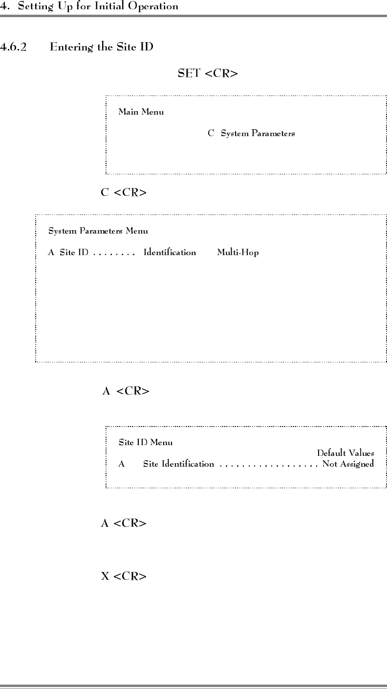
1. At the > prompt, type to display the SET Main Menu.
A RF Boards
B Power Amplifiers
D Alarms
E Set Defaults
2. Type to display the System Parameters Menu.
B Control Channels . . Donor Boosted State
C Voice Channels.... Donor Donor SAT Boosted
D Modem Control.... Passwords Console Time-out Auto-Dial Control
Dial-up Phone Modem Mobile
E Thresholds ....... Hand-In Hand-Back Multi-Donor
Mobile Power RSSI Averaging Hand-In Delay
F Disconnect Control . Donor RSSI SAT Fade Time-out
Hand-Back Delay Hand-Back Attempts
G Call Processing .... RSSI > Thresh Hand-Back / Grab-Back
3. Type to display the Site ID Menu (shown below with
default values).
B Multi-Hop Feature ......................DISABLED
4. Type to access the Site Identification parameter.
5. Enter a name (up to 20 characters) that uniquely identifies the site.
6. Type to back out of the Site ID Menu.
Page 4-14 AMPS EAC-2000™ Manual: Vol. 1, Installation Procedures (27-7655-2, 12/95)
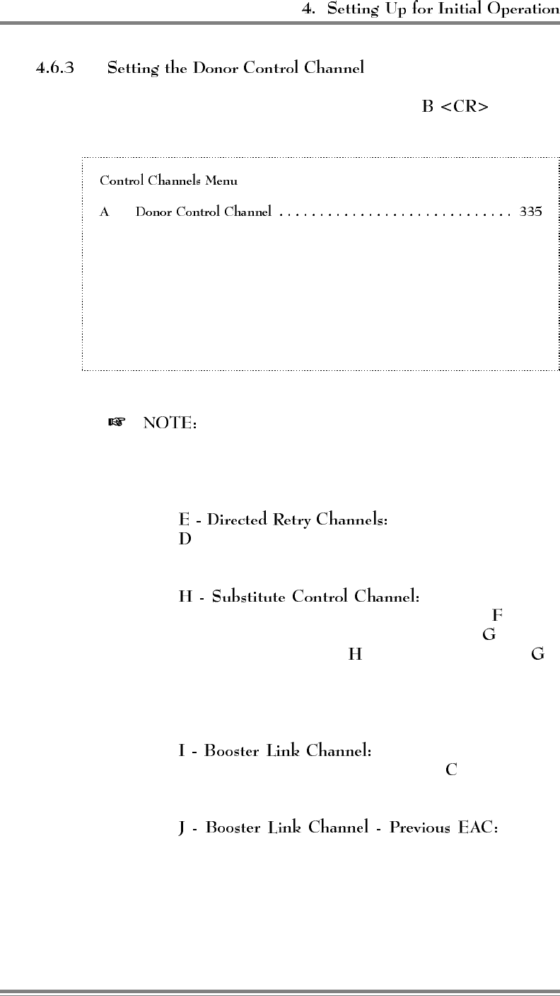
1. From the System Parameters Menu, type to display
the Control Channels Menu.
B Boosted Control Channel ................................ 340
C RF Board To Use For Control Channel ........................ 1
D Control Channel State During "All Channels Busy" . . DIRECTED RETRY
E Directed Retry Channels ................................ LIST
F Back-up Control Channel Option ..................... DISABLED
G Revertive Control Channel Option .................... DISABLED
H Substitute Control Channel ......................... DISABLED
I Booster Link Channel................................... 550
J Booster Link Channel - Previous EAC ....................... 571
This menu represents all selections available on the
Control Channels Menu. Not all selections appear at all times.
Following are selections that are only available when used in
conjunction with other parameters:
• Appears only if selection
(Control Channel State During "All Channels Busy") is
set to Directed Retry.
• Appears only if the
Back-up Control Channel Option (selection ) or the
Revertive Control Channel Option (selection ) is set to
enabled. When selection is disabled and selection is
enabled, board 1 will be used for the last call, but no
control channel will come up when board 1 is boosting a
call.
• Appears only if the Multi-
Donor Activation Threshold (selection on Thresholds
and Power Control Menu) is enabled.
• Appears
only if the Multi-hop Feature is enabled and set to mode
3 or 4.
AMPS EAC-2000™ Manual: Vol. 1, Installation Procedures (27-7655-2, 12/95) Page 4-15
(Continued)
4. Type to access the Donor Control Channel parameter.
5. Enter the channel number (see Section 2.4), then .
6. To return to the Control Channels Menu, type .
1. From the Control Channels Menu, type to access the
Boosted Control Channel parameter. This parameter establishes
the boosted control channel, to which combiner port 1 is tuned.
2. Enter the channel number (see Section 2.4), then .
1. From the Control Channels Menu, type to access the
Directed Retry Channels parameter.
2. Enter the control channel numbers of all nearby cells, including
the donor. The mobile will be directed to attempt calls on these
channels when the EAC-2000 is busy.
3. To return to the System Parameters Menu, type
twice.
Page 4-16 AMPS EAC-2000™ Manual: Vol. 1, Installation Procedures (27-7655-2, 12/95)
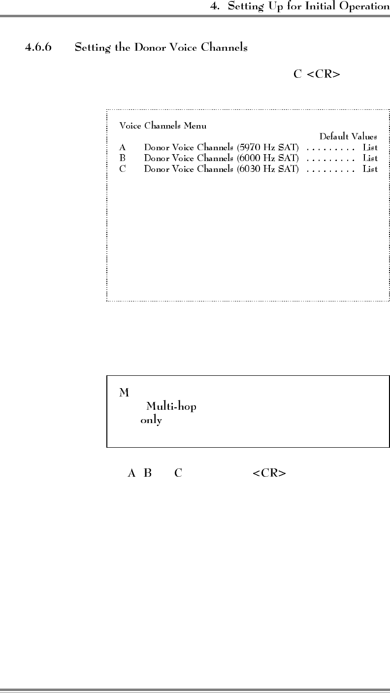
1. From the System Parameters Menu, type to display
the Voice Channels Menu.
M Donor Voice Channels (Multiple SAT) ..............List
2 Boosted Voice Channel Position 2 .................361
3 Boosted Voice Channel Position 3 .................382
4 Boosted Voice Channel Position 4 .................403
5 Boosted Voice Channel Position 5 .................424
7 Boosted Voice Channel Position 7 .................445
8 Boosted Voice Channel Position 8 .................466
9 Boosted Voice Channel Position 9 .................487
10 Boosted Voice Channel Position 10 ................508
11 Boosted Voice Channel Position 11 ................529
2. Notice the SATs for the first three donor voice channel lists.
Determine which list(s) to use for the donor voice channels you
identified earlier (see Section 2.4).
, Donor Voice Channels (Multiple SAT), is for use in
some configurations. Enter channels into this
list if the EAC-2000 is part of a Multi-hop
configuration (as described in Section 10).
3. Type , , or , followed by , to access the Donor
Voice Channels Menu for the corresponding SAT.
AMPS EAC-2000™ Manual: Vol. 1, Installation Procedures (27-7655-2, 12/95) Page 4-17
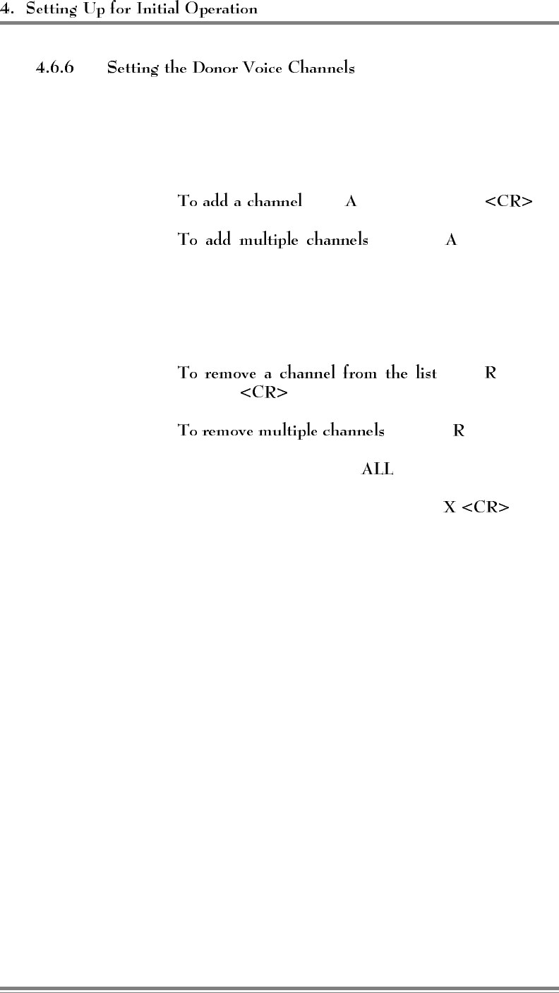
(Continued)
4. Enter channels in the list, as described below. A given channel
may be entered in only one list. The system will support a
maximum of 105 total channels in all four lists (A, B, C, and
M).
a. , type [channel number] .
b. , after the enter multiple
channel numbers separated by commas or spaces. If you
enter a plus (+) sign before a single channel entry, 15
channels will be added, spaced 21 channels apart, starting
with the channel entered. You can then delete extra
channels as necessary.
c. , type [channel
number] .
d. , after the enter multiple
channel numbers separated by commas or spaces. To
remove the entire list, type .
5. To return to the Voice Channels Menu, type .
Page 4-18 AMPS EAC-2000™ Manual: Vol. 1, Installation Procedures (27-7655-2, 12/95)
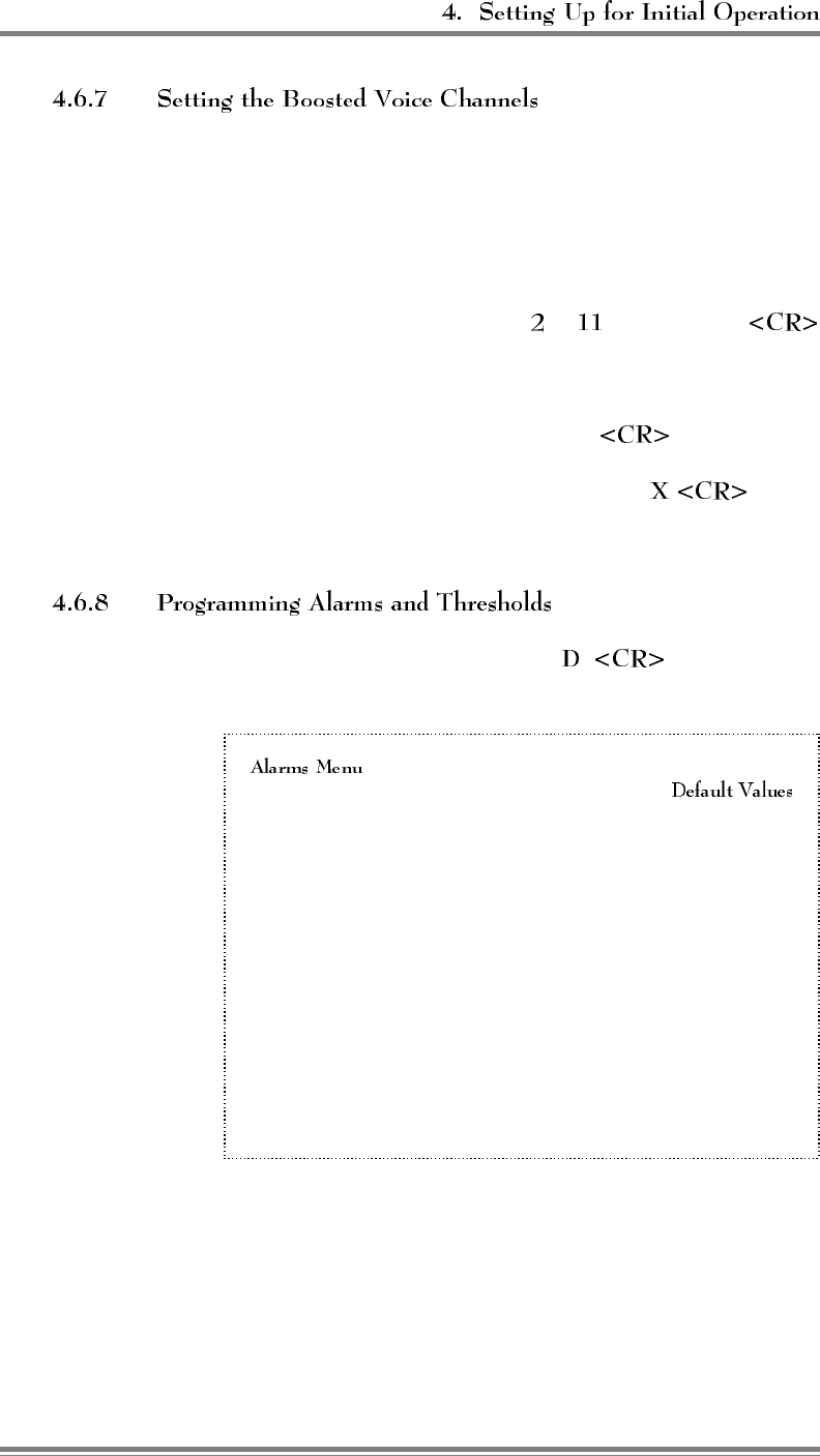
The Voice Channels menu gives you access to boosted voice
channels 2–11, to which combiner ports 2–11, respectively, are tuned.
Boosted channel 1 is normally used to boost the control channel and
does not need to be set. Program channels 2–11 (excluding 6), as
follows.
1. Type the combiner port number ( to ), followed by
to access the desired corresponding Boosted Voice Channel
parameter.
2. Enter the channel number, followed by .
3. To return to the Voice Channels Menu, type .
4. Repeat steps 1–3 for each boosted voice channel.
1. From the SET Main Menu, type to display the
Alarms Menu (shown below with default values).
A M1 Antenna return loss - Low Alarm Point .........6 dB
B M2 Antenna return loss - Low Alarm Point .........9 dB
C PA Temp - High Alarm Point ............... 90 Deg C
D PA Temp - Fan Activation Point ............. 60 Deg C
E PA Temp - PA Power Cutback Point .......... 90 Deg C
F Mobile Power Control causes PA Power Cutback DISABLED
G +28 Volt Supply - PA Power Cutback Point ..... 23.0 Volts
H +28 Volt Supply - Low Alarm Point .......... 23.0 Volts
I +12 Volt Supply - Low Alarm Point .......... 10.0 Volts
J +6 Volt Supply - Low Alarm Point ............5.4 Volts
K External Analog Inputs .................. Alarm Points
L External Digital Inputs .................. Alarm States
M External Digital Outputs ...................... States
N Critical Alarms ................ALARMS REPORTED
O RSSI - Alarms .................... ALARM POINTS
AMPS EAC-2000™ Manual: Vol. 1, Installation Procedures (27-7655-2, 12/95) Page 4-19

(Continued)
2. Type to set the fan activation point (the internal
temperature that causes the cabinet heat exchanger to be turned
on).
The 60oC default setting is adequate for most installations.
Lower the threshold to 50oC if the control channel transmitter
output is increased to its maximum (45W) output level.
3. Type to access the +28 Volt Supply - Low Alarm
Point parameter.
Loss of ac power will cause the EAC-2000 to run on power
from the battery plant (if installed). The battery voltage will
drop to the low alarm point after a period of time, causing an
alarm.
The default value (23.0 V) will be adequate for most
installations. If an external battery plant is used, the low alarm
point may be adjusted upward (e.g., to 25–26 V) if desired to
provide an immediate alarm in the event of the loss of ac
power.
Page 4-20 AMPS EAC-2000™ Manual: Vol. 1, Installation Procedures (27-7655-2, 12/95)

(Continued)
4. If external analog inputs are connected to the EAC-2000
external alarm/controls ports, type to access the
External Analog Inputs menu.
PA 1–6 Cage:
1 Ext. Analog Input 1 Alarm State DISABLED; Input Currently 0.0 Volts
2 Ext. Analog Input 2 Alarm State DISABLED; Input Currently 0.0 Volts
3 Ext. Analog Input 3 Alarm State DISABLED; Input Currently 0.0 Volts
4 Ext. Analog Input 4 Alarm State DISABLED; Input Currently 0.0 Volts
PA 7–11 Cage:
5 Ext. Analog Input 1 Alarm State DISABLED; Input Currently 0.0 Volts
6 Ext. Analog Input 2 Alarm State DISABLED; Input Currently 0.0 Volts
7 Ext. Analog Input 3 Alarm State DISABLED; Input Currently 0.0 Volts
8 Ext. Analog Input 4 Alarm State DISABLED; Input Currently 0.0 Volts
Choose the number of the input(s) connected and program the
alarm point. You may specify DISABLED or
ABOVE/BELOW a threshold, which may be between 0 and 5
Volts.
If PA 7–11 Cage is not included in the unit, then
the hardware for those inputs is not installed and the
alarms should be left as DISABLED.
AMPS EAC-2000™ Manual: Vol. 1, Installation Procedures (27-7655-2, 12/95) Page 4-21
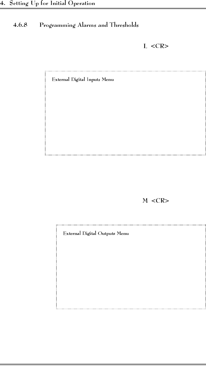
(Continued)
5. If external digital inputs are connected to the EAC-2000
external alarm/controls ports, type to access the
External Digital Inputs menu.
PA 1–6 Cage:
1 Ext. Digital Input 1 Alarm State DISABLED; Input Currently Low
2 Ext. Digital Input 2 Alarm State DISABLED; Input Currently Low
3 Ext. Digital Input 3 Alarm State DISABLED; Input Currently Low
4 Ext. Digital Input 4 Alarm State DISABLED; Input Currently Low
PA 7–11 Cage:
5 Ext. Digital Input 1 Alarm State DISABLED; Input Currently Low
6 Ext. Digital Input 2 Alarm State DISABLED; Input Currently Low
7 Ext. Digital Input 3 Alarm State DISABLED; Input Currently Low
8 Ext. Digital Input 4 Alarm State DISABLED; Input Currently Low
Choose the number of the input(s) connected and program the
alarm state. You may specify DISABLED, HIGH or LOW.
6. If external digital outputs are connected to the EAC-2000
external alarm/controls ports, type to access the
External Digital Outputs menu.
PA 1–6 Cage:
1 Ext. Digital Output 1 State .................... LOW
2 Ext. Digital Output 2 State .................... LOW
3 Ext. Digital Output 3 State .................... LOW
4 Ext. Digital Output 4 State .................... LOW
PA 7–11 Cage:
5 Ext. Digital Output 1 State .................... LOW
6 Ext. Digital Output 2 State .................... LOW
7 Ext. Digital Output 3 State .................... LOW
8 Ext. Digital Output 4 State .................... LOW
Page 4-22 AMPS EAC-2000™ Manual: Vol. 1, Installation Procedures (27-7655-2, 12/95)
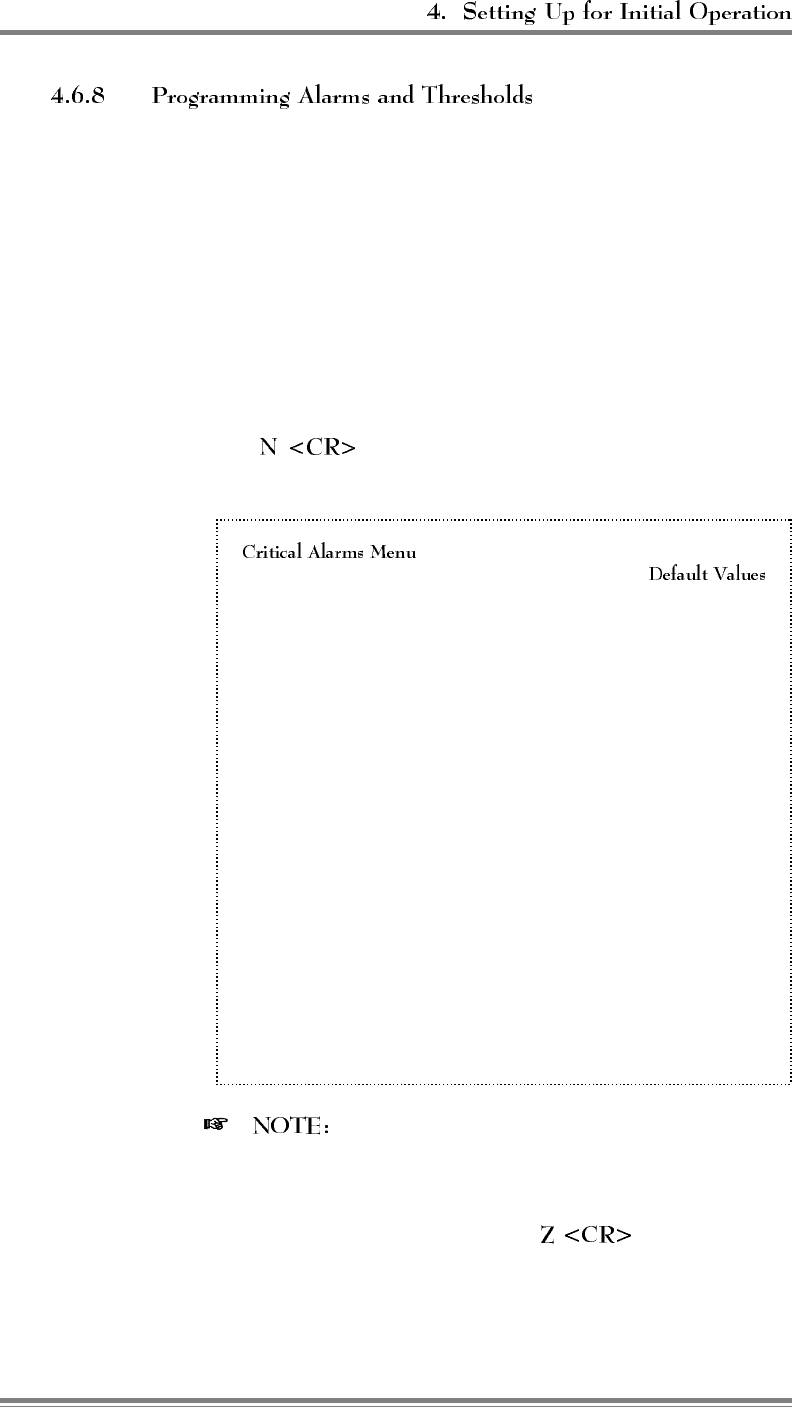
(Continued)
Choose the number of the output(s) connected and program the
desired state. You may specify:
•Low
• Low if critical alarm exists
•High
• High if critical alarm exists
The "low/high if critical alarm exists" options are provided to
allow for connection to external alarm signaling equipment.
7. Type to review the Critical Alarms Menu, shown
here with default values.
A Board Out-of-Service Alarm ............... CRITICAL
B Board ROM Alarm...................... CRITICAL
C Board Calibration Memory Alarm ........... CRITICAL
D Serial Data Link Alarm................... CRITICAL
E Personality Mismatch Alarm ............... CRITICAL
F Synthesizer Unlocked Alarm ............... CRITICAL
G RVS PA Pwr Low Alarm ................. CRITICAL
H RSSI Alarm.......................... LOG ONLY
I PA Out-of-Service Alarm ................. CRITICAL
J PA Temp - High Alarm ................. LOG ONLY
K PA Power - Low Alarm .................. CRITICAL
L PA to Antenna Loss High Alarm ............ CRITICAL
M Antenna Ret Loss Alarm.................. CRITICAL
N ROM Alarm .......................... CRITICAL
O RAM Alarm .......................... CRITICAL
P NOVRAM Alarm ....................... CRITICAL
Q SAT Detector Alarm .................... CRITICAL
R Power Supply Voltages - Low Alarm ......... CRITICAL
S External Analog Input Alarm .............. LOG ONLY
T External Digital Input - Alarms ............ LOG ONLY
Z Display More Critical Alarms
This illustration represents the complete Critical
Alarms Menu. In actual application, only half of the
Critical Alarms Menu can be viewed at a time due to
minimal screen space. To access additional Critical
Alarms Menu selections, type .
AMPS EAC-2000™ Manual: Vol. 1, Installation Procedures (27-7655-2, 12/95) Page 4-23
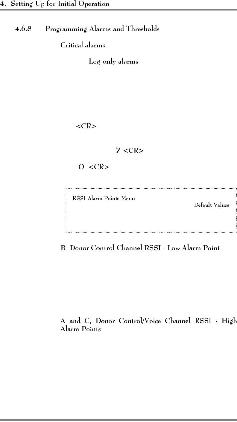
(Continued)
will cause the EAC-2000 to automatically dial
an alarm telephone number when the Auto-Dial feature is
enabled. will be counted and displayed in
the ALA screen, but will not cause the EAC-2000 to dial its
programmed alarm number.
The default values shown above will be adequate for most
installations.
• To change an alarm, type the letter of that alarm and
.
• To alternate between the two Critical Alarms Menu
displays, type .
8. Type at the Alarms Menu to review the RSSI
Alarms Menu.
A Donor Control Channel RSSI - High Alarm Point . . . NONE
B Donor Control Channel RSSI - Low Alarm Point . . -80 dBm
C Donor Voice Channel RSSI - High Alarm Point .... NONE
is the
most critical of these alarm thresholds. This threshold should
be set lower (within a range of -85 to -95 dBm), to ensure
continued operation, under the following circumstances:
• If the booster is being operated at a minimum (-75 dBm)
donor signal level and some fading exists on the donor-to-
booster path.
, may be set at a level 10–15 dB higher than the
normal signal levels being received from the donor, if desired.
This will allow the EAC-2000 to log alarms in the event of IF
board failures with their RSSI measuring circuits.
Page 4-24 AMPS EAC-2000™ Manual: Vol. 1, Installation Procedures (27-7655-2, 12/95)
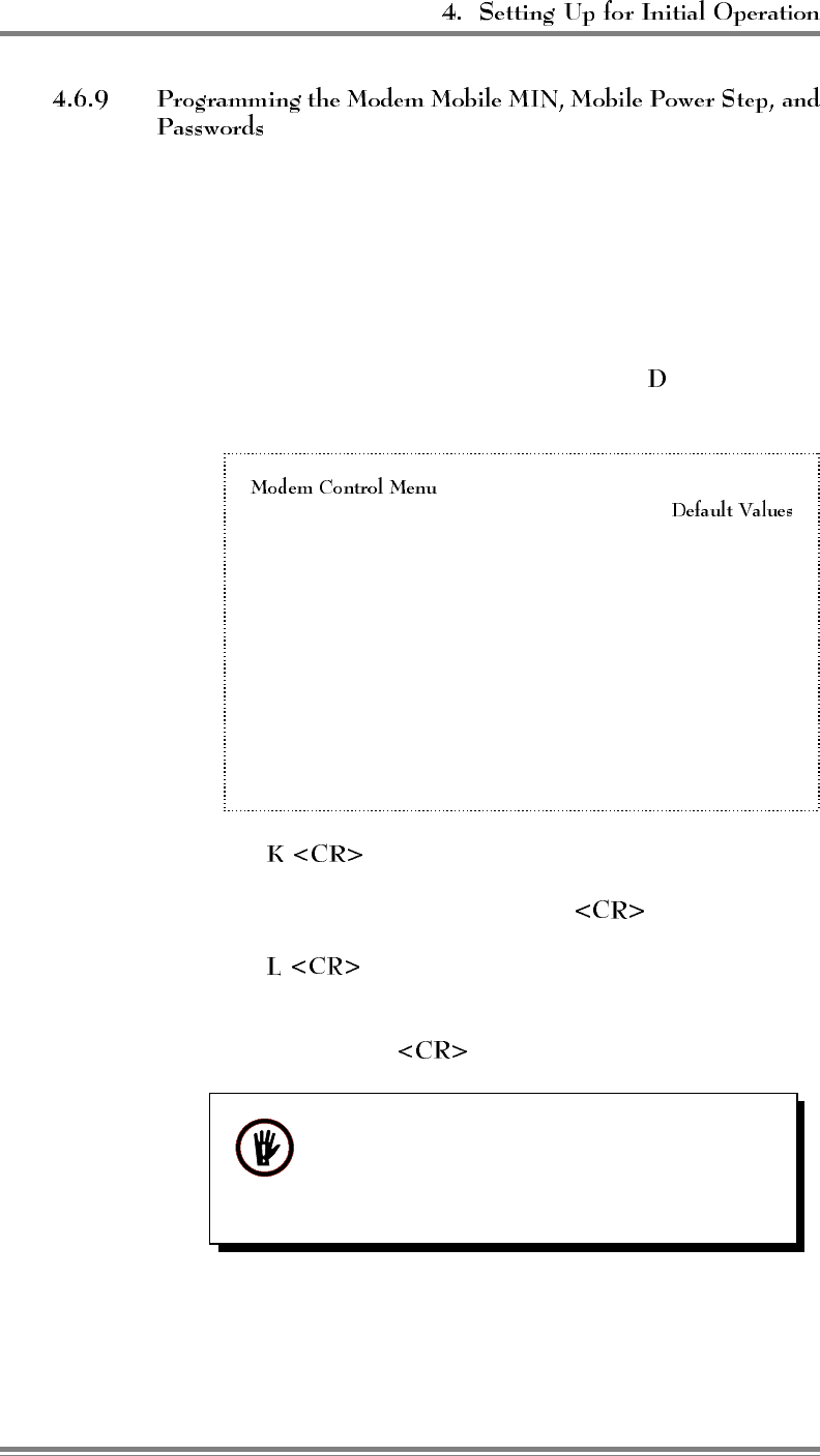
The assigned mobile identification number (MIN) of the mobile and
the desired mobile power step should be loaded into the booster.
This allows the booster to trap calls to and from the remote link to
force operation on the donor voice channels. By doing so, the remote
link does not tie up one of the boosted voice channels. Passwords
may also be programmed now.
1. From the System Parameters Menu, type to display the
Modem Control Menu, shown here with default values.
A Master Password ............................1234
B Restricted Password ..........................5678
C Console Time-out..................... 30 (x 10 Sec)
D Auto-dial Enable ...................... DISARMED
E Dial-up Phone Number 1 ................12163498684
F Dial-up Phone Number 2 .................... NONE
G Auto-dial Trials Max .......................... 10
H Delay Between Auto-dial Retries ............6 (x 10 sec)
I Max Auto-dial Trial Period ................9 (x 10 sec)
J Modem Setup ...................... PARAMETERS
K Modem Mobile MIN ....................1234567890
L Modem Mobile Power Step....................... 7
2. Type to access the Modem Mobile MIN parameter.
3. Enter the 10-digit MIN, followed by .
4. Type to access the Modem Mobile Power Step.
5. Enter the desired power level step (7 = minimum, 0 =
maximum). Enter to record the desired power step.
WARNING!! Use the minimum power step
allowable to minimize the possibility of over-
loading the EAC-2000’s reverse input pre-
amplifier.
6. If desired, use menu entries A and B to enter the passwords.
(They may be left at the defaults for now if desired.)
AMPS EAC-2000™ Manual: Vol. 1, Installation Procedures (27-7655-2, 12/95) Page 4-25
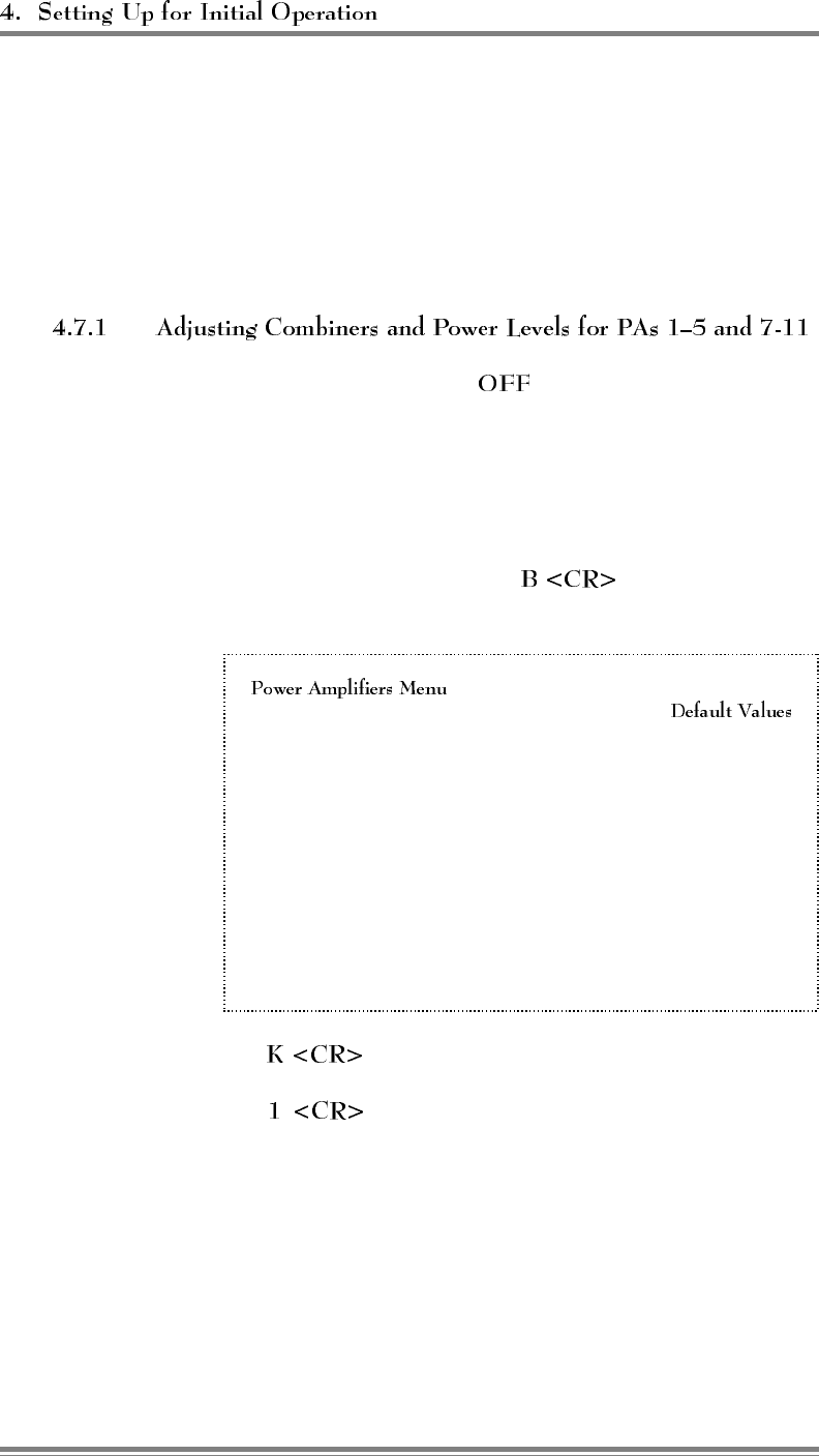
4.7 Tuning Transmitter Combiner and Setting Output Power
The transmitter combiner must be tuned, and output power levels set, whenever
boosted control and voice channels are entered or changed. This process
involves tuning the combiner cavities of PAs 1–5 and 7-11 (if installed) and
adjusting their power output levels, and adjusting the power output level for PA
6.
1. With the system power , connect power measuring
equipment to the M1 antenna port (see Figure 3-5). Remove
the cover plates from the forward combiner(s) to reveal the
combiner tuning screws. Then turn the power back on. Output
power may be monitored using a through-line wattmeter (or a
wattmeter with a built-in load) to monitor output power.
2. From the SET Main Menu, type to display the Power
Amplifiers Menu.
A Forward PA Power Step - Voice ................... 0
B Forward PA Power Step - Control .................. 0
C Forward PA Power Step - Hand-off ................. 0
D Forward PA Power Low Alarm Point - Voice .....+40 dBm
E Forward PA Power Low Alarm Point - Control....+40 dBm
F Forward PA Power Low Alarm Point - Hand-off . . . +40 dBm
G Reverse PA Power Set - Voice ...............+20 dBm
H Reverse PA Power Set - Control ..............+20 dBm
I Reverse PA Power Low Alarm Point - Voice .....+15 dBm
J Reverse PA Power Low Alarm Point - Control ....+15 dBm
K Key Forward PA ..... POWER ADJ/COMBINER TUNING
L Key Reverse PA ............POWER MEASUREMENT
3. Type to key a forward PA.
4. Type to key PA 1 and display the forward power
output as measured at the sensor.
Page 4-26 AMPS EAC-2000™ Manual: Vol. 1, Installation Procedures (27-7655-2, 12/95)
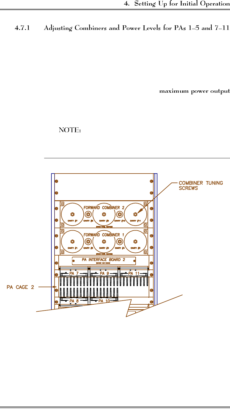
(Continued)
5. Refer to the illustration affixed to the inside of the front door of
the EAC-2000 cabinet to determine which combiner cavities
coordinate with which PAs. Loosen the lock nut and adjust
combiner cavity 1 using a screwdriver.
• If using a wattmeter, adjust for
as indicated by the wattmeter.
• Retighten the lock nut.
The power reading displayed on the terminal will not
vary as the combiner is tuned.
Figure 4-8. Combiner Cavity
AMPS EAC-2000™ Manual: Vol. 1, Installation Procedures (27-7655-2, 12/95) Page 4-27
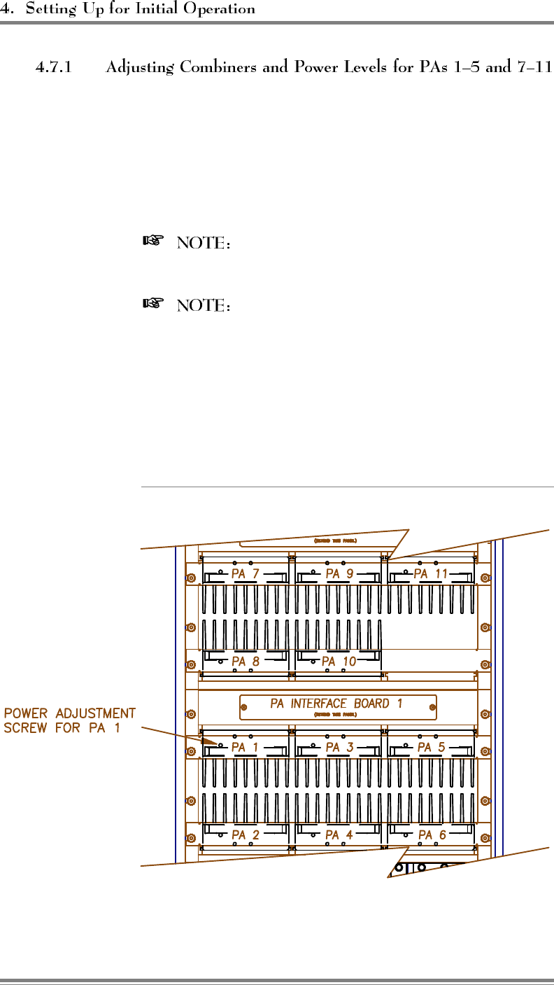
(Continued)
6. Adjust the power output for PA 1 using a small screwdriver or
adjustment tool to turn the PA power potentiometer on the front
of the PA (Figure 4-9). Use a wattmeter, if available, to
measure the power output. Adjust to the level necessary to
meet the authorized ERP level from the antenna.
The control channel output power level is set at
the factory for 10 watts at the M1 antenna connector.
The power level displayed on the terminal is
4 dB higher than the power level at the antenna port
because of cable and combiner losses. The displayed
power ranges from +38 to +47 dBm (7–45 watts), which
corresponds to a range at the M1 antenna connector of
+34 to +43 dBm (3–20 watts). If the displayed power
level is used instead of a wattmeter, take these differences
into consideration.
Figure 4-9. Location of PA Power Potentiometer
Page 4-28 AMPS EAC-2000™ Manual: Vol. 1, Installation Procedures (27-7655-2, 12/95)
(Continued)
7. Note that the PA power potentiometer has a 7–10 dB turn down
range. If the power out cannot be adjusted low enough, hit
to return to the Power Amplifiers Menu.
Select , Forward PA Power Step - Control. This allows entry
of a setting between 0 and 3. Increasing the step by 1 causes
the maximum power out to be reduced by 4 dB (2→8 dB, 3→12
dB). Adjust this parameter in conjunction with the
potentiometer to achieve the desired output power.
8. Repeat steps 3 (selecting a new PA each time) through 7 to
adjust PAs 2-5 and 7-11 (if installed).
If low power out is desired, use selection , Forward PA Power
Step - Voice, for PAs 2–5 and 7–11.
9. When all PAs have been adjusted, make a second pass through
the PAs to check tuning and power levels, and make further
adjustments as needed. This step is needed because one of the
cavities might have been close to the point to which a second
cavity was being tuned. This would cause erroneous power
readings and adjustment during the initial pass.
PA 6 output power does not pass through the combiner. (For a
description of PA 6 function, see Section 2 of Volume 3, Technical
Information.) To adjust its power level—
1. Turn the power off, move the power measuring equipment to
the M2 antenna port, and turn the power back on.
AMPS EAC-2000™ Manual: Vol. 1, Installation Procedures (27-7655-2, 12/95) Page 4-29
(Continued)
2. Key PA 6 and adjust the PA 6 power level as described above.
The power level should be equal to the power level of the voice
channel. Hit to unkey the PA.
If low power out of PA 6 is desired, use selection , Forward
PA Power Step - Hand-off, to reduce the maximum power out.
3. Remove the power measuring equipment. Type
to back out of the SET menu completely. Hit at the
question prompt (defaults NO).
The output power in the reverse direction (from booster to donor cell)
is +20 dBm per channel. It is set at a much lower level than in the
forward direction to prevent reuse interference with other cells that
may be in the system. If the minimum received signal requirements
are met for the forward direction, then by reciprocity +20 dBm per
channel in the reverse direction is sufficient.
Adjustment of the reverse power level is seldom
needed. However, in certain installations the output level may
need to be reduced.
For example, in an installation with a very good path between the
donor cell and the booster, the +20 dBm output level may be so high
that the signal received at the cell site is above the cell site’s dynamic
power control cutback threshold.
In this situation, mobiles handled through the EAC-2000 will be
powered back by the serving cell site. Because the EAC-2000
reverse path attempts to level its output power at +20 dBm no matter
what the received signal strength is, mobiles in this situation will
ultimately be powered back to the minimum (VMAC=7) power level,
and calls will drop.
Page 4-30 AMPS EAC-2000™ Manual: Vol. 1, Installation Procedures (27-7655-2, 12/95)
(Continued)
The +20 dBm output level can be reduced with the following
procedure:
1. From the SET Main Menu, type to display the Power
Amplifiers Menu.
2. Use selections I and J , the reverse PA power for voice and
control channels.
3. Enter the desired level from +5 to +20 dBm.
Another way to remedy this situation is to install pads in increments
of 10 dB between the donor antenna and the donor duplexer ANT
connector. This method has the added advantage of increasing
effective antenna isolation.
Note that the Power Amplifiers Menu also includes the low power
alarm points. The default values are appropriate for PAs set to the
factory power levels (+46.5 dBm forward, +20 dBm reverse).
If the power outs have been adjusted lower than this, reduce the
alarm points as well. Normally, the alarm point should be set 5 dB
lower than the power reported on the terminal while keyed.
AMPS EAC-2000™ Manual: Vol. 1, Installation Procedures (27-7655-2, 12/95) Page 4-31
The EAC-2000 keeps various statistics of calls handled by the booster
and alarms that have been logged:
• Running totals of the number and duration of calls handled per
board can be displayed using the DCS command.
• Incremental totals of certain call statistics can be displayed
using the DCH command.
• Alarms logged since the last system reset can be displayed
using the ALA command.
The EAC-2000 clock is used in updating these statistics. To set the
clock and reset the report values to 0, complete the following steps:
1. At the > prompt, type to access the clock. Enter the
current date and time.
2. Type to reset the Display Call History parameter.
3. Type to reset the Display Call Statistics parameter.
4. Type to reset the Alarm Report parameter.
Page 4-32 AMPS EAC-2000™ Manual: Vol. 1, Installation Procedures (27-7655-2, 12/95)

6HFWLRQ ,QVWDOOLQJWKH5HPRWH/LQN
5.1 Introduction
The AMPS EAC-2000 come equipped with—
• Microcomm TravelPorte MNP-10 modem
• Motorola cellular radio
The modem is compatible with many international modem standards including:
• Bell 103 (300 BPS)
• Bell 212A (1200 BPS)
• CCITT V.21 (300 BPS)
• CCITT V.22 (1200 BPS)
• CCITT V.22 BIS (2400 BPS)
• CCITT V.32 (4800 and 9600 BPS)
• CCITT V.42 (error correction)
• CCITT V.42 BIS (data compression)
• MNP Class 5 (data compression)
The mobile in the EAC-2000 may be dialed using a remote terminal and
compatible modem. In most cases, the Microcomm modem in the EAC-2000
automatically negotiates with the originating modem to determine the highest
speed that the link (and modems) will support. Error correction and data
compression capabilities of the modems are also automatically negotiated, and
if both modems support common protocols, the session will utilize them.
Once the remote link is established, the interface with the system is exactly like
that on the local link, but at a different baud rate. If both links are up,
characters typed on either terminal are echoed to both, along with the resulting
EAC-2000 output. This makes it possible for an experienced operator to
exercise the system remotely while someone watches locally, or for the two to
exercise the system together.
Establishing the remote link involves—
• Setting up service to the mobile radio
• Programming the mobile radio
• Checking out the mobile radio
• Testing the remote link
AMPS EAC-2000™ Manual: Vol. 1, Installation Procedures (27-7655-2, 12/95) Page 5-1
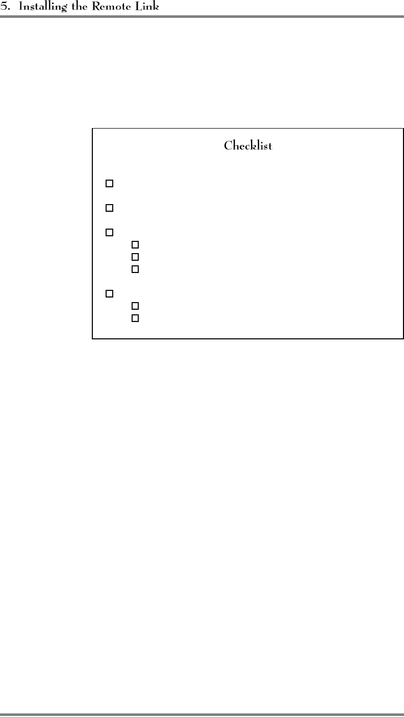
5.1 Introduction (Continued)
The checklist in Figure 5-1 presents a brief overview of these procedures. For
more detailed descriptions of the procedures, refer to Sections 5.2–5.5.
Figure 5-1. Remote Link Installation Checklist
1. Service set up with local supplier. (Sec. 5.2)
2. Mobile radio programmed: (Sec. 5.3)
3. Mobile checked out for proper operation: (Sec. 5.4)
a. Powering up.
b. Call originating.
c. Answering.
4. Remote link tested:
a. EAC-2000 Answering tested. (Sec. 5.5.1)
b. EAC-2000 Originating tested. (Sec. 5.5.2)
5.2 Setting Up Service
1. Set up service to the mobile by contacting the local cellular service
supplier. Provide them with the mobile serial number.
2. Obtain from the service supplier the values for the parameters that will be
programmed into the mobile.
3. Be sure the MIN of the cellular mobile has been loaded into the booster
(see Section 4.6.9).
Page 5-2 AMPS EAC-2000™ Manual: Vol. 1, Installation Procedures (27-7655-2, 12/95)

5.3 Programming the Mobile Radio
The radio is programmed using the supplied handset, which plugs into the front
of the mobile shelf. To program the radio, consult the provided manual or
contact the Extend-A-Cell Hotline.
The sequence to cause the Motorola radio to enter the
programming mode is (total of 13 zeros).
Once programming and initial testing is complete, the handset should be
removed and stored in the cabinet.
5.4 Checking Out the Mobile
After the mobile has been set up and programmed, check it for proper operation
by completing the following steps.
1. With the handset connected, power up the EAC-2000. After a short while,
the "no sequence" indication should disappear.
• If the mobile does not come into service, check the antenna, the
antenna connection and the mobile programming.
2. Make sure the mobile can originate and answer calls in the conventional
fashion. The mobile with the handset can be used to communicate with a
partner while trying to optimize the booster performance.
3. Dial the mobile using another cellular phone. The mobile should ring a
few times, then answer, then send about several seconds of answer-back
tone (1800 Hz).
AMPS EAC-2000™ Manual: Vol. 1, Installation Procedures (27-7655-2, 12/95) Page 5-3
5.5 Testing the Remote Link
After the remote link has been installed and programmed, you should test its
operation. The EAC-2000 should be able to answer calls placed from the
remote link. It should also be able (if so programmed) to place calls to a
predetermined number when certain alarm conditions exist.
The EAC-2000 constantly monitors and answers incoming calls even
if it is being exercised via the local link. To test the booster’s ability
to answer calls from the remote link, complete the following steps.
1. Ensure that the remote link has been installed as required:
• Conventional ASCII terminal
• Modem: Microcomm TravelPorte MNP-10 compatible
modem
• Terminal and modem set to—
- Appropriate baud rate for the modem
- 7 data bits, even parity, 1 stop bit
- Full duplex (no local echo)
2. Dial the phone number of the mobile in the EAC-2000. (After
about one ring, the EAC-2000 will answer and try to set up
communication.)
• If the modems fail to connect, the modems will terminate
the call after a set period of time.
• If the modems are successful in establishing a link, the
remote modem will indicate CONNECT.
3. Type . (The familiar EAC-2000 response should
appear.)
If there are illegible characters, check the modem/terminal
parameter setup.
Page 5-4 AMPS EAC-2000™ Manual: Vol. 1, Installation Procedures (27-7655-2, 12/95)

The EAC-2000 constantly monitors and logs several alarm conditions.
These conditions can be viewed using the ALA command. They are
described in Volume 2, Operating Procedures.
Each type of alarm can be defined as "critical" or "log only" using
the SET command. If an alarm defined as critical occurs more than
a predetermined number of times, a is said to exist.
The system indicates any critical alarms at the beginning of each
communication session.
The system can also be set up to call a predetermined number if a
critical alarm exists. (The default setup is to place a call when
a critical alarm exists.) If the system has been programmed to
automatically report alarms, it will attempt to do so only if all of the
following conditions exist:
• A critical alarm exists.
• The console is locked.
• The mobile is connected and in service.
• The system has not successfully reported an alarm since the
"Auto-Dial Enable" parameter was set to ARMED.
• The system has not unsuccessfully tried to report an alarm more
than the designated number of times (the Auto-Dial Trials Max
parameter) since the Auto-Dial Enable parameter was set to
ARMED.
AMPS EAC-2000™ Manual: Vol. 1, Installation Procedures (27-7655-2, 12/95) Page 5-5
(Continued)
When an auto-dial call is made, the
following sequence occurs:
1. As the call is auto-dialed, the local console displays DIALING
REMOTE LINK. ( from the local link at this point will
abort the attempt.)
2. After the number is dialed, the EAC-2000 waits up to 90
seconds for a remote modem to answer and establish a
connection.
3. Five seconds after connect, the EAC-2000 automatically lists the
alarm report (see ALA Command in Volume 2, Operating
Procedures). The report is echoed locally.
4. If the connection stays up for the duration of the report listing,
the attempt is considered successful. The EAC-2000 disarms
itself after a successful call to prevent duplicate reports.
5. After the report, the system waits up to 60 seconds for a <CR>.
If a <CR> is received, a normal interactive session begins.
Otherwise, the EAC-2000 ends the call.
6. If a second dial-up phone number is programmed, the sequence
will be repeated using the second number.
The system will abort the call and
consider the attempt a failure if either of the following occurs:
• The modems do not connect within a set period of time (the
programmed "Max Auto-Dial Trial Period" parameter, default
90 seconds).
• The modems connect but lose the connection before the entire
report is listed.
After a failed attempt, the system will display the message
ORIGINATION ATTEMPT FAILED on the local console. It will then
wait a specified period of time (the programmed "Delay Between
Auto-Dial Retries" parameter). If all the conditions for making the
call are still in effect, another attempt will be made.
One way to test the call origination feature is to artificially create an
alarm by setting the +28 Volt Supply - Low Alarm Point to +35
Volts.
Page 5-6 AMPS EAC-2000™ Manual: Vol. 1, Installation Procedures (27-7655-2, 12/95)

6HFWLRQ 2SWLPL]LQJ3HUIRUPDQFH
6.1 Introduction
After the EAC-2000 has been installed, the system must be checked out to
determine if adjustments to the hand-in ndk threholds eded to ensure optimum
performance.
6.2 Determining Hand-in and Hand-back Thresholds
To determine hand-in and hand-back thresholds, conduct coverage tests using
equipment whose power and antenna configuration match the predominate
customer equipment in the coverage area. Conduct the tests as follows:
1. Select the default hand-in and hand-back thresholds as a starting point for
initial system testing. These thresholds will serve adequately for many
installations.
2. Test these thresholds throughout the coverage area from an automobile
with an outside cellular antenna. For best results, use a cellular mobile
capable of displaying received signal levels and the channel on which it is
operating. Make signal level measurements by monitoring the boosted
control channel. Make calls to a test number to determine whether the call
is set up via the booster or whether the mobile is being handed in or out
of the boosted area.
Make sure the hand-back threshold is at least 5 dB below the hand-in
threshold. Setting the thresholds too low or too high can result in the
following types of problems:
• Unnecessary boosting of mobiles that
otherwise will have good service from the donor.
• Missing some mobiles that need
boosting.
• Excessive noise on the call before
it is handed back to the original voice channel.
• Too many hand-back attempts by
the EAC-2000.
AMPS EAC-2000™ Manual: Vol. 1, Installation Procedures (27-7655-2, 12/95) Page 6-1
6.3 Setting Hand-in and Hand-back Thresholds
To change threshold settings, complete the following steps:
1. From the System Parameters Menu, type to access the
Thresholds and Power Control Menu.
Thresholds and Power Control Menu Default Values
A Mobile Dynamic Power Control Threshold ................. -60 dBm
B Hand-in Threshold .................................. -90 dBm
C Multi-Donor Activation Threshold .....................DISABLED
D Hand-back Threshold ............................... -100 dBm
E Hand-in Mobile Power Step ................................ 0
F Hand-back Mobile Power Step .............................. 0
G RSSI Averaging Speed .............................. MEDIUM
H Delay Between Hand-in Attempts ......................... 5 Sec
I Station Power Class Selective Boosting . BOOST ALL POWER CLASSES
2. Type to access the Hand-in Threshold parameter. This
parameter sets the signal level threshold at which a mobile on one of the
donor voice channels becomes a candidate for boosting.
3. Enter the new threshold. The hand-in threshold has an allowable range of
-100 dBm to -40 dBm. Entering 0 disables the threshold.
4. Type to return to the Thresholds and Power Control Menu.
5. Type to access the Hand-back Threshold parameter. This
parameter sets the signal level threshold at which a mobile being boosted
becomes a candidate for returning to the original donor site voice channel.
6. Enter the new threshold. The hand-back threshold has an allowable range
of -120 dBm to -20 dBm. Entering 0 disables the threshold.
The default values shown for the other parameters (menu entries A, E, F,
G, H and I) are adequate for most installations. Refer to Volume 2,
Operating Procedures, for explanations of these parameters if adjustment
is necessary. Refer to Volume 1, Section 8, for setting the Multi-Donor
Activation Threshold (menu entry C).
Page 6-2 AMPS EAC-2000™ Manual: Vol. 1, Installation Procedures (27-7655-2, 12/95)
6HFWLRQ 0XOWL+RS 2SHUDWLRQ
7.1 Introduction
Two or more EAC-2000 units may be set up to operate together in a line—for
example, along a major corridor leading into a metropolitan area. This is
referred to as . EAC-2000s and Extend-A-Cell IVs may
also be mixed in a Multi-hop configuration. An example of a Multi-hop
configuration is shown below.
Donor
Cell ⇔Booster
#1 ⇔Booster
#2 ⇔Booster
#3
7.2 How Multi-Hop Operation Works
The boosters are set up so that there is a two-way RF path between the donor
and booster #1 and between each pair of adjacent boosters. This arrangement
can be used to handle situations in which a mobile—
• Places or answers a call while in the coverage area of any of the boosters.
• Drives across the coverage boundary:
- Donor-to-booster
- Booster-to-booster (away from donor)
- Booster-to-booster (toward donor)
- Booster-to-donor
When a mobile places or answers a
call, the first exchange of information occurs on the reverse control channel
(from mobile to donor). If the call is a mobile-answered call, the exchange is
a page response. If it is a mobile-originated call, the mobile does an access.
There is little difference in the way EAC-2000 boosters handle these two. Since
the mobiles self-locate, the control channel chosen for the access determines in
which booster's coverage area (if any) the mobile is located.
AMPS EAC-2000™ Manual: Vol. 1, Installation Procedures (27-7655-2, 12/95) Page 7-1

7.2 How Multi-Hop Operation Works (Continued)
All boosters between the terminating
booster and the donor cell repeat the access or page response and decode it.
From the decoding they extract the mobile identification number (MIN). Next,
the cellular system assigns a voice channel to that particular mobile by sending,
over the forward control channel, an initial voice channel designation (IVCD)
message consisting of the mobile’s MIN and a voice channel that will be used
by the donor for the call.
The Multi-hop boosters are all monitoring the forward control channel data
stream. The boosters that decode the access or page response on the reverse
control channel also decode the corresponding IVCD message on the forward
channel and change the channel to one of its boosted channels.
Booster #1 substitutes its chosen boosted channel for the donor voice channel
in the IVCD message and sets up a boost path between the donor-assigned voice
channel and the boosted voice channel of booster #1. Likewise, booster #2
changes the channel number in the IVCD message and sets up a boost path
between the boosted voice channels of boosters #1 and #2.
All of the boosters between the terminating EAC-2000, where the call is placed,
and the donor cell will in this fashion identify that particular mobile as a
candidate for repeating and will decode the associated IVCD messages.
7.3 Installing the EAC-2000 in Multi-Hop Configuration
When installing the EAC-2000 in Multi-hop configuration, you should give
special attention to—
• Achieving antenna isolation and signal level
• Enabling the Multi-hop feature
• Entering the EAC position
• Selecting boosted channels for each unit
• Assigning a booster link channel
• Setting hand-back and hand-in thresholds
Page 7-2 AMPS EAC-2000™ Manual: Vol. 1, Installation Procedures (27-7655-2, 12/95)
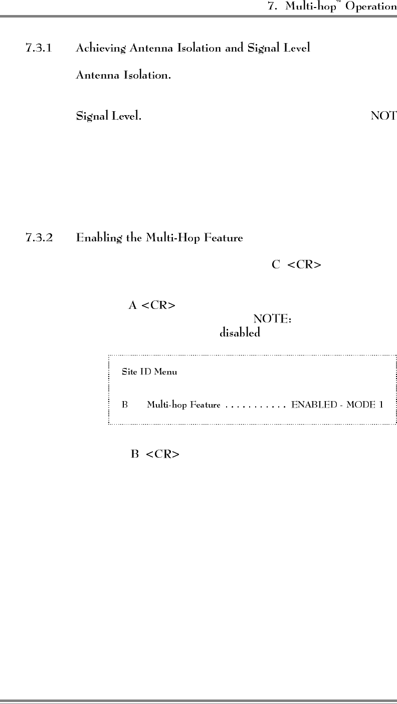
The antenna isolation requirements for Multi-
hop operation are the same as for standard operation.
For optimum performance, each booster that is
adjacent to the donor requires a forward signal level from the
previous booster in the chain of at least -70 dBm (at the D1 antenna
connector).
Each booster along the path must be able to communicate with the
previous and next booster only. They are not required to be able to
receive from or to transmit back to the donor cell site.
1. From the SET Main Menu, type to display the
System Parameters Menu.
2. Type to display the Site ID Menu, shown here with
the Multi-hop Feature enabled. ( The default setting for
the Multi-hop Feature is .)
A Site Identification......................Not Assigned
3. Type to access the Multi-hop Feature parameter.
The following choices will appear:
(0) Disabled
(1) Enabled Mode 1–Adjacent to donor
(2) Enabled Mode 2–Adjacent to EAC-2000
(3) Enabled Mode 3–Adjacent to an EAC-IV (no prior EAC-
2000 in chain)
(4) Enabled Mode 4–Adjacent to an EAC-IV (with prior
EAC-2000 in chain)
AMPS EAC-2000™ Manual: Vol. 1, Installation Procedures (27-7655-2, 12/95) Page 7-3
(Continued)
4. Select the proper mode. This depends only upon the kind of
equipment that is adjacent to the EAC-2000.
•Use if the EAC-2000 is the first in the chain,
adjacent to the donor cell.
•Use if the previous equipment is another EAC-
2000.
•Use if the previous equipment is an EAC-IV, and
this is the closest EAC-2000 to the donor.
•Use if the previous equipment is an EAC-IV, but
there is at least one EAC-2000 between this and the donor.
If Mode 3 or 4 is used, the "Booster Link Channel Previous
EAC" will appear in the Control Channels Menu. The booster
link channel number for the EAC-IV should be entered.
• The EAC-IV "position" parameter should be entered as "1" if
the previous equipment is an EAC-2000. The EAC-2000
appears to be a donor to the EAC-IV.
A set of boosted channels must be chosen for each EAC-2000 in a
multi-hop configuration. A particular EAC-2000 may be viewed as
having the previous booster in the chain as a "donor."
Page 7-4 AMPS EAC-2000™ Manual: Vol. 1, Installation Procedures (27-7655-2, 12/95)
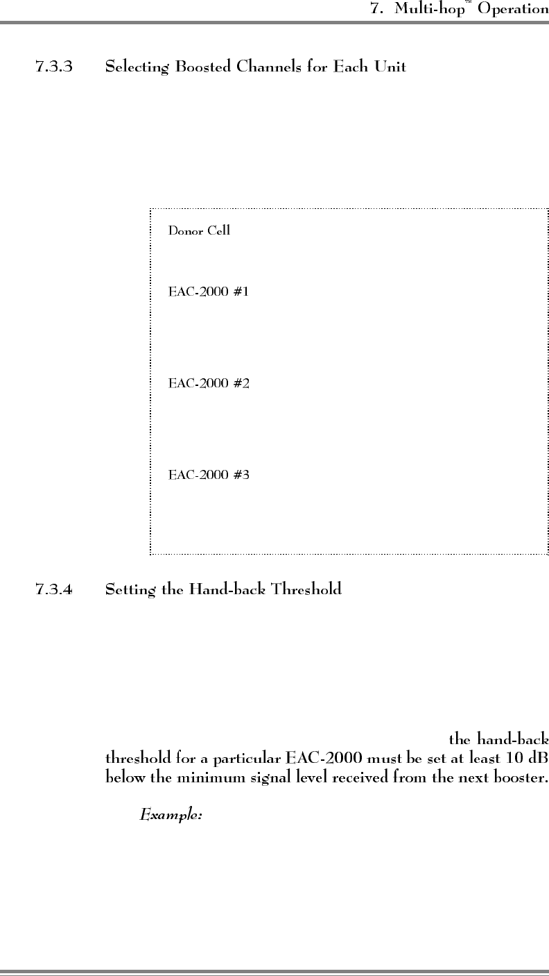
(Continued)
Therefore, in choosing the boosted channel set for a particular
booster, ensure that the set is separated by at least three channels (90
kHz) from the channel sets of both the previous booster and the next
one.
Figure 7-1. Example of Valid Channel Set
Control channel: 316
Voice channels: 1,22,43,64,85,106,127,148,169,...295
Boosted control channel: 319
Donor control channel: 316
Boosted voice channels: 4,25,46,67
Donor voice channel list: 1,22,43,64,85,106,127,148,169,...295
Boosted control channel: 322
Donor control channel: 319
Boosted voice channels: 7,28,49,70
Donor voice channel list: 4,25,46,67
Boosted control channel: 325
Donor control channel: 322
Boosted voice channels: 10,31,52,73
Donor voice channel list: 7,28,49,70
For a Multi-hop configuration, there is an additional consideration in
setting the hand-back threshold (the signal level at which mobiles are
considered "weak," causing the mobile to be handed back to the
previous EAC-2000 in the chain).
An EAC-2000 has no way of detecting whether a given call is being
handled directly or by the next booster. Therefore,
If booster #1 typically experiences a reverse signal
level of -90 dBm from booster #2 when booster #2 is handling
a call, then booster #1 should have its hand-back threshold no
higher than -100 dBm. Otherwise, booster #1 might mistake a
call being handled by booster #2 (or #3) as a weak mobile and
try to hand it back to the donor cell. This would probably
result in a dropped call.
AMPS EAC-2000™ Manual: Vol. 1, Installation Procedures (27-7655-2, 12/95) Page 7-5
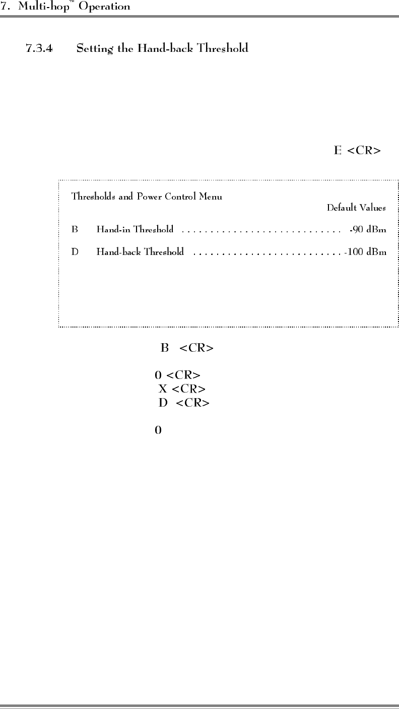
(Continued)
To determine the hand-back threshold, the following procedure is
recommended:
1. Disable the hand-in and hand-back thresholds for all boosters in
the chain, as follows:
a. From the System Parameters Menu, type: to
display the Thresholds and Power Control Menu.
A Mobile Dynamic Power Control Threshold ................ -60 dBm
C Multi-Donor Activation Threshold .................... DISABLED
E Hand-in Mobile Power Step ................................ 0
F Hand-back Mobile Power Step .............................. 0
G RSSI Averaging Speed ..............................MEDIUM
H Delay Between Hand-in Attempts ......................... 5 sec
I Station Power Class Selective Boosting . BOOST ALL POWER CLASSES
b. Type to access the Hand-in Threshold
parameter.
c. Type to disable the hand-in threshold.
d. Type to return to the Thresholds menu.
e. Type to access the Hand-back Threshold
parameter.
f. Type to disable the hand-back threshold.
2. After powering up all of the EAC-2000 units, verify that the
received signal levels meet the minimum needed.
3. Verify call operation with each booster, in good signal level
conditions (within 1/2 mile of the booster). Make sure that calls
can stay up at least 1 minute to eliminate link fading as a
problem.
Page 7-6 AMPS EAC-2000™ Manual: Vol. 1, Installation Procedures (27-7655-2, 12/95)

(Continued)
4. Establish a to use for the hand-back threshold:
a. Set up a call on the last EAC-2000 in the chain at a good
signal level position, sitting still.
b. With the call up, monitor and record the reverse signal
levels received by each booster all the way back to the
donor. To do this—
• Use the SCS command (from the > prompt) to
identify which board pair is handling the call.
• Type (capital or lower case). The reverse signal
level is reported for the board that is handling the
call.
The hand-back threshold should be at least 10 dB below the
reverse RF level received when the next booster is handling the
call. The allowable range is -120 dBm to -20 dBm.
If a system of boosters were spread out so that
all were receiving -70 dBm in the forward direction, then
the reverse signal levels from the next booster would be
about -92 dBm. In this situation, the highest hand-back
threshold recommended would be -102 dBm. If the
threshold were set higher (e.g., -95 dBm), then normal
signal level variations would cause an EAC-2000 to hand
back a mobile actually being handled by another booster.
Set the new hand-back threshold as follows:
1. From the System Parameters Menu, type to display
the Thresholds and Power Control Menu.
2. Type to access the Hand-back Threshold parameter.
3. Enter the new threshold, followed by .
There are no new limitations imposed upon the hand-in threshold in
a Multi-hop configuration. However, it must be
for that same EAC-2000.
The allowable range is -120 dBm to -20 dBm.
Review the hand-in threshold to be sure it meets these criteria, and
adjust it if necessary.
AMPS EAC-2000™ Manual: Vol. 1, Installation Procedures (27-7655-2, 12/95) Page 7-7

6HFWLRQ 2SHUDWLRQZLWK0XOWL'RQRU 8QLWV
8.1 Introduction
The basic EAC-2000 handles most cases of hand-in and hand-back to the donor
cells. However, in installations where the EAC-2000 is adjacent to more than
one donor, the "hand-back to a different cell site" situation requires special
consideration.
If a mobile being boosted back to one donor cell drives toward
another donor cell, a dilemma occurs. The serving cellular system
thinks the mobile is on one voice channel, while the booster actually
has it translated to another channel.
Under normal operation, the signal at the donor from the booster is
usually below the system’s hand-off threshold. Thus, the donor will
always identify the mobile as a candidate for hand-off, and the
cellular system will try to find the mobile in the cell sites adjacent to
the donor. However, because the mobile is actually on the booster’s
translated voice channel, it will not be seen in any adjacent or nearby
cell site. Therefore, the system will not hand the mobile to another
cell unless special means are provided to allow that cell site to
measure the signal level of the boosted mobile.
This can be resolved by providing the adjacent cell sites with
equipment with which to see the mobile on the voice channel that the
cellular system thinks it is on. The cellular system can then
determine which adjacent cell the mobile is driving into, assign a
voice channel in that cell, and then send a hand-off message sending
the mobile to that channel.
This can be achieved by placing a reverse-translating Multi-Donor
Unit (MDU) at each of the cell sites adjacent to the booster.
AMPS EAC-2000™ Manual: Vol. 1, Installation Procedures (27-7655-2, 12/95) Page 8-1

The MDU, which is connected to the cell-site receive antennas,
scans for boosted mobiles and then translates those mobiles back to
the donor’s voice channel for presentation to the cell-site locating
receiver.
The MDUs must know the relationships in effect between boosted
and donor channels for calls being handled by the EAC-2000
booster(s). This is accomplished by data signaling between the EAC-
2000 and any adjacent MDUs on a booster link channel.
The EAC-2000 looks for the boosted mobile signal level to fall below
a settable . If this happens, the
booster encodes and transmits the channel relationships to any MDUs
that may be listening. This does not mean, however, that the mobile
will necessarily be handed off. Transmission of this information
merely allows the MDU to know (if it is able to see the mobile signal
at a sufficient level) to which channel it should "untranslate" the
mobile.
For a more complete description of MDU operation,
see the Multi-Donor Extend-A-Cell® IV Technical Manual.
8.2 Installing the EAC-2000 for MDU Operation
When installing the EAC-2000 for operation with Multi-Donor Units, give
special attention to—
• Achieving adequate signal level at the booster and at the MDU
• Assigning a booster link channel
• Setting a multi-donor activation threshold
Page 8-2 AMPS EAC-2000™ Manual: Vol. 1, Installation Procedures (27-7655-2, 12/95)
The following signal level requirements apply to MDU
configurations:
• If more than one donor cell site is to be used, then signal levels
from each site must be at least -75 dBm at the EAC-2000.
• Signal levels on the reverse path (from the EAC-2000 to each
donor cell site) must arrive at the donor cell sites at
approximately the same amplitude. (This is necessary to keep
the cellular system from erroneously trying to hand the mobile
from one donor cell to the other.)
• Reverse path signals that arrive at the donor cell sites from the
EAC-2000 must be within the hand-off hysteresis window used
by the cellular system.
This signal balancing (if necessary) is usually accomplished by using
multiple directional donor antennas at the EAC-2000, with the
stronger path being attenuated with pads to match the weaker path.
Another alternative is to increase the hand-off hysteresis window in
the cellular system for the particular donor cell sites that are under
consideration.
Signal levels should be measured using a spectrum analyzer or FM
service monitor. RF attenuators should be used on stronger signals
to bring them within ± 1 dB of weaker signals.
If MDUs are installed at cell sites adjacent to the EAC-2000, the RF
path between the EAC-2000 M2 antenna and the "Booster Link
Antenna" of the MDUs must be such that the MDU units can receive
at least a -100 dBm signal when the booster transmits using PA 6
(the hand-off PA).
When installing antennas, ensure that this requirement is met.
AMPS EAC-2000™ Manual: Vol. 1, Installation Procedures (27-7655-2, 12/95) Page 8-3
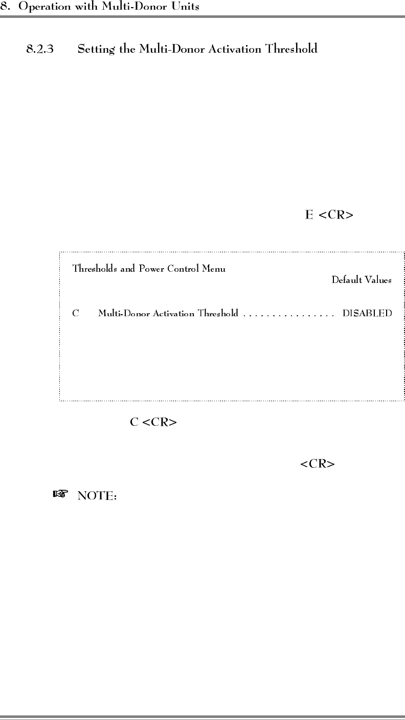
The multi-donor activation threshold defaults to DISABLED. In this
condition, it does not allow the transmission of channel relationship
messages to MDUs. Therefore, you will need to set the multi-donor
activation threshold in order to operate with MDUs. Usually, a
threshold halfway between the hand-in threshold and the hand-back
threshold will give good performance without generating excessive
transmissions to the MDUs.
To set the threshold, complete the following steps:
1. From the System Parameters Menu, type to display
the Thresholds and Power Control Menu.
A Mobile Dynamic Power Control Threshold ................ -60 dBm
B Hand-in Threshold ................................. -90 dBm
D Hand-back Threshold ...............................-100 dBm
E Hand-in Mobile Power Step ................................ 0
F Hand-back Mobile Power Step .............................. 0
G RSSI Averaging Speed ..............................MEDIUM
H Delay Between Hand-in Attempts ......................... 5 sec
I Station Power Class Selective Boosting . BOOST ALL POWER CLASSES
2. Type to access the Multi-Donor Activation Threshold
parameter.
3. Enter the chosen threshold, followed by .
For additional hints on achieving successful multi-donor
operation and on troubleshooting, refer to the Multi-Donor Unit
technical manual.
Page 8-4 AMPS EAC-2000™ Manual: Vol. 1, Installation Procedures (27-7655-2, 12/95)

A booster link channel must be assigned. Choose a channel that
meets the following requirements:
• May be any channel in the band (control or voice), including
the extended band voice channels.
• Must be different from any donor or boosted channel in the
same EAC-2000.
• Should meet the same separation considerations as for a voice
channel.
One way of meeting these requirements is to assign one of the
unused voice channels in the same 23-channel separation sequence as
the link channel.
To enter the booster link channel, open the Control Channels Menu
after setting the thresholds.
If both Multi-hop configuration and Multi-Donor Units are used, the
single booster link channel will be used for both types of signaling.
AMPS EAC-2000™ Manual: Vol. 1, Installation Procedures (27-7655-2, 12/95) Page 8-5

6HFWLRQ 5HVHUYHGIRU)XWXUH8VH
AMPS EAC-2000™ Manual: Vol. 1, Installation Procedures (27-7655-2, 12/95) Page 9-1
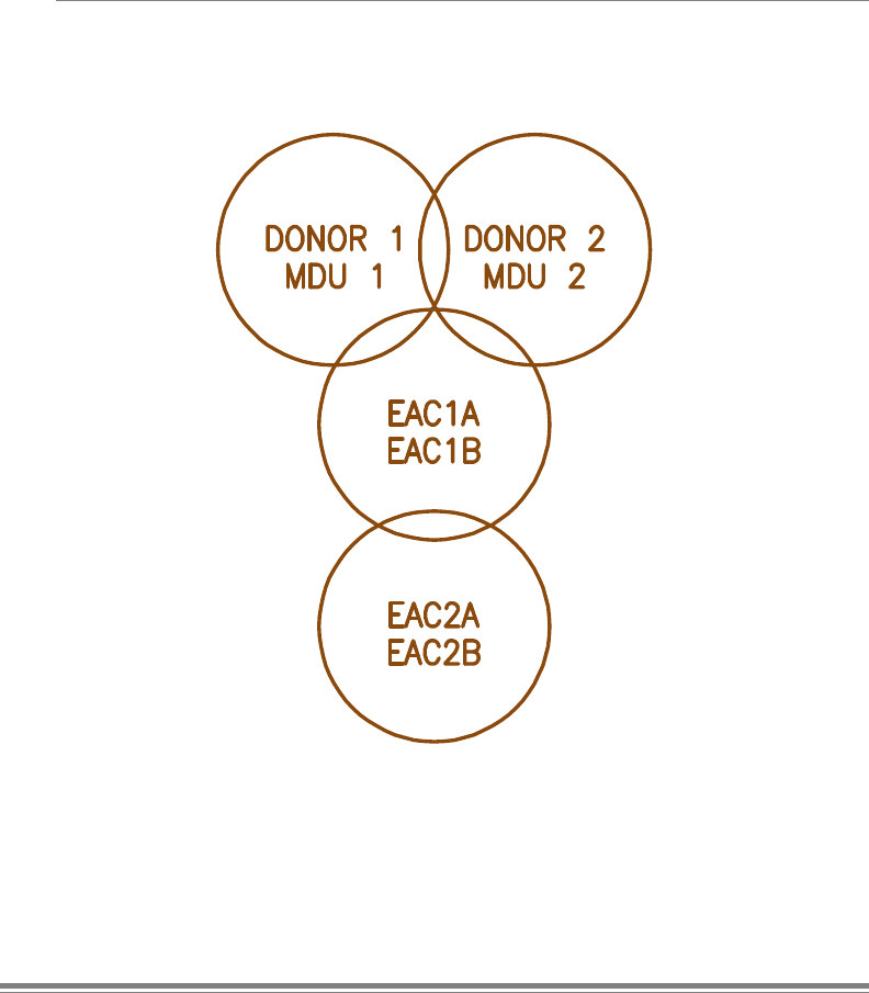
6HFWLRQ &RPELQHG2SHUDWLRQ
0XOWL&DELQHW0XOWL+RS0XOWL'RQRU
10.1 Introduction
EAC-2000 installations may be set up to combine Multi-cabinet operation,
Multi-hop operation and multi-donor units (MDUs). Figure 10-1 shows an
example of a complex configuration of donor cell sites, EAC-2000
cabinets, and MDUs.
Figure 10-1. Combined Configuration Example
AMPS EAC-2000™ Manual: Vol. 1, Installation Procedures (27-7655-2, 12/95) Page 10-1
10.2 Installing the EAC-2000 for Combined Operation
When installing the EAC-2000 for combined operation, the
following requirements must be met:
• A unique booster link channel must be set for each
cabinet.
• Any listening MDUs must include the booster link
channels of all cabinets in nearby EAC-2000s in their lists.
• The boosted voice channels of the EAC-2000 sites must
be at least three channels (90 kHz) away from any
possible donor channel.
• The Booster Link Channel–Previous EAC parameters must
be set to the booster link channel of the previous EAC-
2000 cabinet that is boosting the control channel (for
Mode 3 or Mode 4 EAC-2000s).
• Donor voice channels must be listed in the
in the following situation:
- EAC 2 is not adjacent to the primary donor cell.
- A previous booster in the chain (EAC 1) has more
than one possible donor (donors 1 and 2).
- EAC 1 could boost calls from either donor to
EAC 2.
- The donor voice channels for EAC 1 must be listed
in the multiple SAT list for EAC 2.
Figure 10-2 shows a set of channel assignments (given the
donor control channels) that meets these requirements for the
configuration shown in Figure 10-1. Other valid choices are
also possible. In this figure, notice that:
• In EAC 2A, the donor voice channels in the multiple SAT
list include all of the boosted voice channels from EAC
1A (4,25,46,67) and EAC 1B (109,130,151,172,193).
• Minimum separation of three channels is maintained
between donor and boosted channels.
Page 10-2 AMPS EAC-2000™ Manual: Vol. 1, Installation Procedures (27-7655-2, 12/95)

Figure 10-2. Channel Assignment Example
Cell/Unit Channel Type Channels
Donor 1 Control channel ................ 316 (SAT 5970)
Voice channels ................. 1,22,43,64,85,106,127,148,169 ...295
Donor 2 Control channel ................ 325 (SAT 6000)
Voice channels ................. 10,31,52,73,94,115,136,157,178 ... 304
MDU 1 Booster link channel list .......... 88,214
MDU 2 Booster link channel list .......... 88,214
EAC 1A Boosted control channel ........... 319
Donor control channel ............ 316
Boosted voice channels ........... 4,25,46,67
Donor voice channels (SAT = 5970) . . 1,22,43,64,85,106,127,148...295
Booster link channel ............. 88
Booster link channel—previous EAC . (Not used)
EAC 1B Boosted control channel ........... (Not used)
Donor control channel ............ (Not used)
Boosted voice channels ........... 109,130,151,172,193
Donor voice channels (SAT = 6000) . . 10,31,52,73,94,115,136,157...304
Booster link channel ............. 214
Booster link channel—previous EAC . (Not used)
EAC 2A Boosted control channel ........... 322
Donor control channel ............ 319
Boosted voice channels ........... 7,28,49,70
Donor voice channels (SAT = Multiple) 4,25,46,67,109,130,151,172,193
Booster link channel ............. 91
Booster link channel—previous EAC . (Not used)
EAC 2B Boosted control channel ........... (Not used)
Donor control channel ............ (Not used)
Boosted voice channels ........... 112,133,154,175,196
Donor voice channels ............ (empty)
Booster link channel ............. 217
Booster link channel—previous EAC . (Not used)
AMPS EAC-2000™ Manual: Vol. 1, Installation Procedures (27-7655-2, 12/95) Page 10-3

9ROXPH
2SHUDWLQJ3URFHGXUHV
27-7656-2
Issue 12/95
© Copyright 1995 Allen Telecom Systems
All Rights Reserved

Field Support
If you need technical assistance with the EAC-2000™, contact
at one of the following telephone numbers:
Extend-A-Cell : (800) 800-EAC4 (3224)
or (216) 349-8413
Systems Engineering Department: (216) 349-8413

&RQWHQWV
............................................. vi
.......................................... 1-1
1.1 About This Volume ................................ 1-1
1.2 Overview of EAC-2000 Operation ....................... 1-2
1.2.1 Establishing the Local Link ....................... 1-2
1.2.2 Establishing the Remote Link ...................... 1-4
1.3 Entering Commands ................................ 1-6
1.3.1 Syntax ...................................... 1-6
1.3.2 Command Entry ............................... 1-7
1.3.3 Moving Through SET Menus ...................... 1-7
1.3.4 Escaping from Continuous Cycles ................... 1-8
1.3.5 Ending a Session............................... 1-8
1.4 Overview of Commands.............................. 1-9
....................................... 2-1
2.1 Introduction ...................................... 2-1
2.1.1 SET Menu Map ............................... 2-1
2.1.2 Parameter Summaries ........................... 2-1
2.2 Main Menu...................................... 2-12
2.3 RF Boards Menu .................................. 2-12
2.3.1 RF Board Position Menus ....................... 2-13
• Status ................................... 2-13
• Diversity ................................. 2-14
2.4 Power Amplifiers Menu ............................. 2-14
• Forward PA Power Step - Voice................. 2-15
• Forward PA Power Step - Control ............... 2-15
• Forward PA Power Step - Hand-off .............. 2-15
• Forward PA Power Low Alarm Point - Voice ....... 2-16
• Forward PA Power Low Alarm Point - Control ...... 2-16
• Forward PA Power Low Alarm Point - Hand-off ..... 2-17
• Reverse PA Power Set - Voice.................. 2-18
• Reverse PA Power Set - Control................. 2-18
• Key Forward PA ........................... 2-18
• Key Reverse PA............................ 2-19
AMPS EAC-2000™ Manual: Vol. 2, Operating Procedures (27-7656-2, 12/95) Page iii

Contents
(Continued)
2.5 System Parameters Menu ............................ 2-19
2.5.1 Site ID Menu ................................ 2-20
• Site Identification ........................... 2-20
• Multi-Hop Feature .......................... 2-20
2.5.2 Control Channels Menu ......................... 2-21
• Donor Control Channel ....................... 2-21
• Boosted Control Channel ...................... 2-22
• RF Board to Use for Control Channel ............. 2-22
• Control Channel State During "All Channels Busy" . . . 2-23
• Directed Retry Channels ...................... 2-24
• Back-up Control Channel Option ................ 2-24
• Revertive Control Channel Option................ 2-25
• Substitute Control Channel ..................... 2-25
• Booster Link Channel ........................ 2-26
• Booster Link Channel—Previous EAC ............ 2-26
2.5.3 Voice Channels Menu .......................... 2-27
• Donor Voice Channel Lists (5970–6030 Hz SAT) .... 2-28
• Donor Voice Channels List (Multiple SAT) ......... 2-29
• Boosted Voice Channel Positions 2–5 and 7-11 ...... 2-29
2.5.4 Modem Control Menu .......................... 2-30
• Master Password............................ 2-30
• Restricted Password ......................... 2-31
• Console Time-out ........................... 2-31
• Auto-Dial Enable ........................... 2-31
• Dial-up Phone Numbers (1 and 2) ............... 2-32
• Auto-Dial Trials Max ........................ 2-33
• Delay Between Auto-Dial Retries ................ 2-34
• Max Auto-Dial Trial Period .................... 2-34
• Modem Setup.............................. 2-35
• Init String ................................ 2-35
• Dial Prefix String ........................... 2-37
• Hang Up String ............................ 2-37
• Local Port Baud Rate ........................ 2-38
• Local Port Comm Params ..................... 2-28
• Remote Port Baud Rate ....................... 2-39
• Remote Port Comm Params .................... 2-40
• Remote Port Handshake....................... 2-40
• Modem Mobile MIN ......................... 2-41
• Modem Mobile Power Step .................... 2-41
Page iv AMPS EAC-2000™ Manual: Vol. 2, Operating Procedures (27-7656-2, 12/95)

Contents
(Continued)
2.5.5 Thresholds and Power Control Menu................ 2-42
• Mobile Dynamic Power Control Threshold ......... 2-42
• Hand-in Threshold .......................... 2-43
• Multi-Donor Activation Threshold ............... 2-44
• Hand-back Threshold ........................ 2-45
• Hand-in Mobile Power Step .................... 2-45
• Hand-back Mobile Power Step .................. 2-45
• RSSI Averaging Speed ....................... 2-46
• Delay Between Hand-in Attempts ................ 2-47
• Station Power Class Selective Boosting ............ 2-47
2.5.6 Disconnect Control Menu ........................ 2-48
• Donor RSSI ............................... 2-48
• SAT Fade Time-out ......................... 2-49
• Max Num of Hand-back Attempts Per Call ......... 2-49
• Minimum Delay between Hand-back Attempts ....... 2-50
2.5.7 Call Processing Parameters Menu .................. 2-50
• Mobile RSSI>Threshold Parameters .............. 2-51
• Hand-back/Grab-back Control................... 2-51
2.6 Alarms Menu .................................... 2-52
2.6.1 Antenna Return Loss - Low Alarm Point ............. 2-51
2.6.2 PA to Antenna Loss - High Alarm Point ............. 2-53
2.6.3 PA Temperature - High Alarm Point ................ 2-52
2.6.4 PA Temperature - Fan Activation Point .............. 2-53
2.6.5 PA Temp - PA Power Cutback Point................ 2-54
2.6.6 Mobile Power Control Causes PA Power Cutback ....... 2-55
2.6.7 +28 Volt Supply - PA Power Cutback Point ........... 2-55
2.6.8 +28 Volt Supply - Low Alarm Point ................ 2-56
2.6.9 +12 Volt Supply - Low Alarm Point ................ 2-56
2.6.10 +6 Volt Supply - Low Alarm Point ................ 2-56
2.6.11 External Analog Inputs Menu .................... 2-57
2.6.12 External Digital Inputs Menu ..................... 2-58
2.6.13 External Digital Outputs Menu ................... 2-59
2.6.14 Critical Alarms Menu .......................... 2-60
2.6.15 RSSI - Alarm Points Menu ...................... 2-61
• Donor Control Channel RSSI - High Alarm Point ..... 2-61
• Donor Control Channel RSSI - Low Alarm Point ..... 2-61
• Donor Voice Channel RSSI - High Alarm Point ...... 2-62
2.7 Set Defaults Feature ................................ 2-62
AMPS EAC-2000™ Manual: Vol. 2, Operating Procedures (27-7656-2, 12/95) Page v

Contents
............................ 3-1
3.1 Introduction ...................................... 3-1
3.2 SSS (Show System Status) Command .................... 3-3
3.3 SCS (Show Call Status) Command ...................... 3-5
3.4 RSS (RSSI Report) Command.......................... 3-9
3.5 SSR (Scanned RSSI Report) Command .................. 3-10
3.6 PWR (PA Power Display) Command.................... 3-12
3.7 SAT (SAT Report) Command......................... 3-13
3.8 ALA (Alarm Report) Command ....................... 3-14
3.9 DCS (Display Call Statistics) Command .................. 3-20
3.10 DCH (Display Call History) Command .................. 3-27
3.11 TIM (Time Display and Change) Command ............... 3-29
3.12 MIN (Mobile ID Number) Command .................... 3-30
3.13 REV (Show Hardware Revisions) Command .............. 3-32
..................................... 4-1
4.1 Introduction ...................................... 4-1
4.2 Commands ....................................... 4-1
1-1. Commonly Used Commands ............................. 1-9
2-1. SET Command Menu Map............................... 2-2
2-2. RF Board Parameters ................................... 2-3
2-3. Power Amplifier Parameters .............................. 2-3
2-4. System Parameters .................................... 2-4
2-5. Alarm Parameters .................................... 2-10
3-1. Sample SSS Report .................................... 3-2
3-2. Sample SCS Report.................................... 3-5
3-3. Sample List of RSSI Readings ............................ 3-9
3-4. Sample List of Power Readings .......................... 3-12
3-5. Sample List of SAT Readings............................ 3-13
3-6. Sample ALA Report .................................. 3-15
3-7. Sample DCS Report .................................. 3-21
3-8. Sample DCH Report .................................. 3-22
3-9. Sample TIM Screen................................... 3-28
3-10. Sample MIN Screen .................................. 3-30
Page vi AMPS EAC-2000™ Manual: Vol. 2, Operating Procedures (27-7656-2, 12/95)
6HFWLRQ ,QWURGXFWLRQ
1.1 About This Volume
This is the second of three volumes pertaining to the AMPS EAC-2000™
booster. Extensive monitor software is included with the EAC-2000 system,
which allows the installer or service provider to control and monitor the system’s
performance. This manual is intended to assist the installer or service provider
in using the provided software to ensure optimum performance of the EAC-
2000.
This volume describes the terminal interface to the EAC-2000, which is used to
set parameters, monitor call activity and call statistics, and report and diagnose
problems. It includes procedures for entering commands and setting parameters
and provides information on interpreting the results. The volume is divided into
four sections:
• Provides an overview of EAC-2000 operation
via local and remote serial link, guidelines for command entry, and an
overview of the commands that may be entered.
• Describes all of the submenus that can be
accessed through the SET command and provides guidelines for setting
parameters.
• Describes commands that
can be used to obtain information on EAC-2000 operations, and guidelines
for interpreting the results.
• Describes various higher level
commands used to verify hardware.
For instructions on installing the EAC-2000, setting initial parameters, and
making adjustments to achieve optimum performance, refer to Volume 1,
Installation Procedures. For a more detailed description of the EAC-2000 and
how it works, refer to Volume 3, Technical Information.
AMPS EAC-2000™ Manual: Vol. 2, Operating Procedures (27-7656-2, 12/95) Page 1-1

1.2 Overview of EAC-2000 Operation
Virtually all of the operating parameters of the EAC-2000 are under software
control. These parameters can be changed and monitored locally, through a
serial link attached to a standard RS232, ASCII terminal or personal computer.
The same control can be exercised remotely via a telephone line, modem, and
the same kind of terminal.
The EAC-2000 communicates with a conventional ASCII, RS232
terminal connected to the 25-pin D-sub connector on the controller
board. To bring up the local link:
1. Connect and power up the terminal.
2. Set the terminal for 9600 baud, even parity, 7 data bits, 1 stop
bit, full duplex (no local echo). If possible, set the terminal to
all capitals, disable auto XON/XOFF and soft scroll, and
"carriage return only" (not carriage return plus line feed).
3. Power up the EAC-2000 (see Volume 1, Section 4). After
several seconds, the terminal should respond CONSOLE
LOCKED.
4. Press (carriage return or enter). A welcome message
and prompt for password should appear. If the password is not
prompted for, the "password bypass" switch is activated.
If the response is illegible, check the terminal setup. If nothing
comes up, power down and recheck the power hookup, the
terminal hookup, and terminal setup. If you are not sure of the
EAC-2000 terminal setup or password, see note following step
#5.
5. Enter a master password (the default master password is 1234)
or restricted password. A master password gives access to all
system setup and monitor commands. A restricted password
gives access to only certain system monitor commands.
An accepted password should result in a salutation followed by
the command entry level prompt (>).
Page 1-2 AMPS EAC-2000™ Manual: Vol. 2, Operating Procedures (27-7656-2, 12/95)

(Continued)
If you forget the password or terminal setup. . .
The password and the terminal setup may be changed by the user during a
session. If the settings were forgotten, it would not normally be possible to
bring up the local link. A mechanism is provided to recover from this
situation.
PA interface board 1 is located on PA cage 1, behind a panel. On this board
is a 4-position dip switch. Switch 1 is "password bypass enable."
If you have forgotten the password, but know the terminal setup (i.e., a
carriage return causes the welcome message to appear, but your password is
not accepted), perform the following procedure:
1. Set the password bypass switch to "on."
2. Hit <CR> at the terminal. The password is not required now.
3. Type SET <CR> and examine/change the password.
4. Set the password bypass switch to "off."
If you have forgotten the terminal setup, perform the following procedure:
1. Set the password bypass switch "on."
2. Cycle power on the EAC-2000. The local port will operate at 9600,
7 even, 1 stop (regardless of how it was set).
3. Change the terminal to 9600, 7 even, 1 stop and hit <CR>. The
welcome message should appear and the password will be bypassed.
4. Type SET <CR> and examine/change the modem setup and the
password. Exit SET.
5. Set the password bypass switch to "off."
6. Type LOC <CR>. The local port will operate as SET.
7. Change the terminal setup to match the setup entered with SET.
8. Hit <CR> to open up the local port at the new setup. Record the
setup.
AMPS EAC-2000™ Manual: Vol. 2, Operating Procedures (27-7656-2, 12/95) Page 1-3

The EAC-2000 utilizes an MNP-10 compatible modem and Motorola
cellular mobile.
This equipment makes it possible to dial up and communicate with
the EAC-2000 using a remote terminal and modem of either type
listed. The EAC-2000 modem automatically determines the type of
modem calling it and adapts to its baud rate. The EAC-2000 can also
be set up to automatically dial a predetermined telephone number if
a major fault occurs.
Once the remote link is established, the interface with the system is
exactly like that on the local link, but at a different baud rate. If both
links are up, characters typed on either terminal are echoed to both,
along with the resulting EAC-2000 output. This makes it possible for
an experienced operator to exercise the system remotely while
someone watches locally, or for the two to exercise the system
together.
For instructions on setting up and testing the cellular mobile and for
answering calls originated by an EAC-2000, refer to Volume 1,
Section 5.
Page 1-4 AMPS EAC-2000™ Manual: Vol. 2, Operating Procedures (27-7656-2, 12/95)

(Continued)
To communicate with the EAC-2000 from a remote location:
1. Hook up a conventional ASCII terminal through a compatible
modem.
2. Set the terminal and modem to 4800, 2400 or 1200, 7 data bits,
even parity, 1 stop bit, full duplex (no local echo). If possible,
set the terminal to all capitals.
3. Dial the phone number of the mobile in the EAC-2000. After
about one ring, the EAC-2000 will answer and try to set up
communications by providing a continuous answer-back tone.
If the modems fail to connect, the EAC-2000 will terminate the
call. If they are successful in establishing a link, the remote
modem will indicate CONNECT.
If you dial the EAC-2000 with a high-speed
(above 1200) modem, the modems may take up to a
minute to negotiate the link.
4. Press and look for the welcome message. From this
point on, communicating over the remote link is similar to
communicating over the local link.
When both links are established, the baud rate on the local
link will slow to match the remote link rate.
The remote link is more prone to transmission errors
because of the noisier link. These errors, while a
nuisance, do not cause major problems because the system
always asks for confirmation of serious changes.
AMPS EAC-2000™ Manual: Vol. 2, Operating Procedures (27-7656-2, 12/95) Page 1-5

1.3 Entering Commands
The system responds to commands that consist of three letters
followed by up to three data fields, as follows:
In this syntax—
• COM is the particular three-letter command.
• FIELD 1 consists of up to four hex characters followed by a
hyphen (-).
• FIELD 2 consists of up to four hex characters followed by an
equals (=) sign.
• FIELD 3 consists of up to four hex characters.
• Each command ends with a carriage return (<CR>).
After the COMmand has been entered, the system usually prompts
for data it needs. If a certain field is not required, any data entered
in that field will be ignored.
Page 1-6 AMPS EAC-2000™ Manual: Vol. 2, Operating Procedures (27-7656-2, 12/95)
When entering commands—
• Spaces may be added to separate the fields, after the first three
letters have been entered.
• Leading zeros may be omitted.
• Use DELETE or BACKSPACE to correct mistakes.
• End the command with .
Command Entry Symbols
>Command entry level prompt. Indicates that the
system is ready to accept commands.
<CR> Carriage return or enter.
<CTRL> Control. The control key is used in combination
with other keys. For example, <CTRL> Z means
to hold down the control key while pressing the
Z key.
ESC Escape. A single key marked ESC on most
keyboards.
The SET command gives access to a progression of menus used to
set EAC-2000 parameters (see Section 2). Use the keystrokes
described below to move forward and backward through these menus.
• Moving Forward. Each command brings up a menu of items
from which to choose, with a character in front of each item.
To select an item, type the character and . The next
menu (or the parameter to be changed) will be displayed.
• To move backward along a path, type
, or just . The previous menu will be displayed.
Repeat until you are back at the SET Main Menu.
• Type at any menu level. Or, type
while at the Main Menu level.
AMPS EAC-2000™ Manual: Vol. 2, Operating Procedures (27-7656-2, 12/95) Page 1-7
Some commands cause a continuous process to begin. To escape this
mode and return to the > prompt, hit or type .
Entering or from the > prompt will
cause the characters entered on the line to be erased.
A session can be ended using LOC, RES, or the inactivity timeout.
• Should be used if the session involves only
system monitoring or minor parameter changes. Ensures
security but lets alarms and call statistics continue to
accumulate. Will terminate remote link.
• Should be used if extensive parameter
changes have been made during a session. Ensures that all
parameter changes take effect, since all hardware is initialized
after a reset. Ensures security because the password must be re-
entered to get back to the command level. Initializes all alarm
condition counters to 0. Will terminate remote link.
• Inactivity timer (default 5 minutes) will
terminate any currently running command, and simulates LOC,
if a keyboard entry is not detected within the designated period.
Avoid leaving the EAC-2000 in an insecure state if the remote
link is lost before the session is properly ended. This will
terminate the remote link.
Page 1-8 AMPS EAC-2000™ Manual: Vol. 2, Operating Procedures (27-7656-2, 12/95)
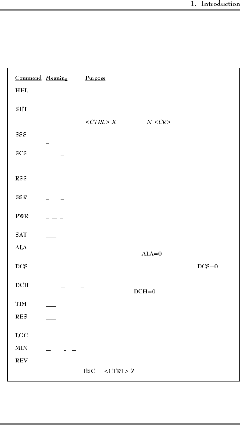
1.4 Overview of Commands
Figure 1-1 presents a summary of the most commonly used commands.
Figure 1-1. Commonly Used Commands
HELp Lists syntax and function for system commands. (If session
was begun with restricted password, gives abbreviated list.)
SETup Invokes a menu-driven entry mode used to inspect or change all
EAC-2000 operating parameters. (To exit this command, type
and answer .)
Show System Lists current EAC-2000 parameter settings and conditions of
Status monitored input parameters.
† Show Call Shows current status of each board pair. Updates listing if
Status status changes (e.g., if a call is set up or taken down) and gives
reason for the change.
† RSSI Report Gives continuously updated reading of the received signal
strength on all RF boards.
†Show Scanned Shows average RSSIs of 18 channels being scanned.
RSSI
†PoWeR Repeatedly lists power readings on the 7 PAs.
display
†SAT report Repeatedly lists SAT readings on all boards.
ALArm report Reports number of times various alarm conditions occurred
since last system reset. ( zeroes alarm counts.)
Display Call Displays various call statistics per board pair. (
Statistics zeroes statistics.)
Display Call Displays hourly totals of certain call statistics for the
History last running week. ( zeroes some of these.)
TIMe Displays/changes current clock time.
RESet Resets EAC-2000, preserves parameters in effect when
command is issued.
LOCk Forces password entry before accepting other commands.
†Mobile ID Nbr. Lists the last five access attempts by mobiles.
REVision Displays hardware revisions within the EAC-2000.
† To exit this command, hit or .
AMPS EAC-2000™ Manual: Vol. 2, Operating Procedures (27-7656-2, 12/95) Page 1-9

6HFWLRQ 6(7&RPPDQG
2.1 Introduction
From the command entry level prompt (>), the SET command invokes the setup
utility which displays a progression of menus. The menus provide a guided path
to each EAC-2000 parameter.
Figure 2-1 illustrates the paths to follow through the SET menus to reach
each available parameter.
Figures 2-2 through 2-5 summarize the RF board, power amplifier,
system, and alarm parameters that can be programmed using the SET
command. Following the parameter summaries, each SET menu and its
associated parameters are described in detail.
AMPS EAC-2000™ Manual: Vol. 2, Operating Procedures (27-7656-2, 12/95) Page 2-1
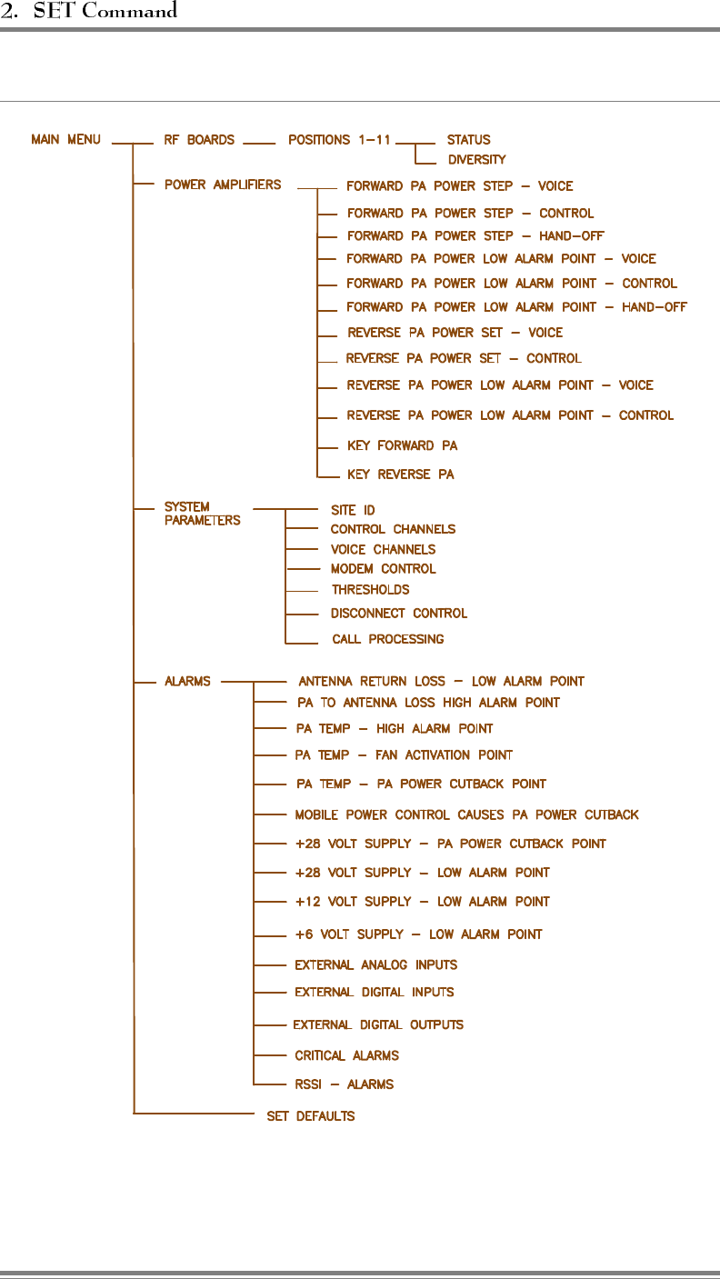
Figure 2-1. SET Command Menu Map
Page 2-2 AMPS EAC-2000™ Manual: Vol. 2, Operating Procedures (27-7656-2, 12/95)
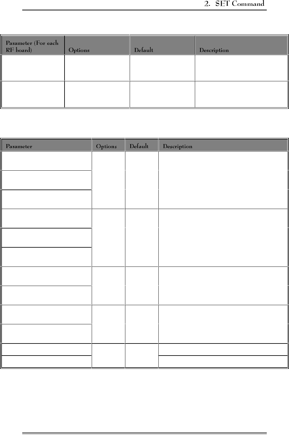
Figure 2-2. RF Board Parameters
STATUS Disabled
Enabled
None
Enabled Defines how the board is to be
activated.
DIVERSITY Diversity ON
Antenna M1 selected
Antenna M2 selected
Varies according to
board
Defines antenna to use for reverse
receiver.
Figure 2-3. Power Amplifier Parameters
FORWARD PA POWER STEP -
VOICE
0–3 0 Sets the output power electronically to one of
four levels. Each step is about -4 dB.
FORWARD PA POWER STEP -
CONTROL
FORWARD PA POWER STEP -
HAND-OFF
FORWARD PA POWER LOW
ALARM POINT - VOICE
0, 30–50 +40 dBm Sets low power alarm threshold for forward PAs.
Should be 5 to 6 dB below power read using
"key forward."
FORWARD PA POWER LOW
ALARM POINT - CONTROL
FORWARD PA POWER LOW
ALARM POINT - HAND-OFF
REVERSE PA POWER SET
VOICE
5–20 dBm +20 dBm Sets reverse output power level (referenced at D1
antenna).
REVERSE PA POWER SET
CONTROL
REVERSE PA POWER LOW
ALARM POINT - VOICE
0, 1–23 +15 dBm Sets low power alarm threshold for reverse PAs.
Should be 5 dB below power read using "key
reverse."
REVERSE PA POWER LOW
ALARM POINT - CONTROL
KEY FORWARD PA PAs 1–11 Keys PAs for power adjust and combiner tuning.
KEY REVERSE PA Keys reverse PA for reverse power monitoring.
AMPS EAC-2000™ Manual: Vol. 2, Operating Procedures (27-7656-2, 12/95) Page 2-3

Figure 2-4. System Parameters
SITE ID Up to 20 characters Not assigned Identifies the site for remote mode
operation.
MULTI-HOP
FEATURE
(0) Disabled
(1) Enabled - Mode 1
(2) Enabled - Mode 2
(3) Enabled - Mode 3
(4) Enabled - Mode 4
Disabled Turns Multi-hop operation on or off.
DONOR CONTROL
CHANNEL
1–799, 991–1023 337 Channel used as the input for
frequency translation. Should be set
to donor site control channel.
BOOSTED CONTROL
CHANNEL 1–799, 991–1023 340 Channel to which donor control
channel is translated. Should be
separated from donor control channel
and any possible donor voice channel
by at least three channels (90 kHz).
RF BOARD TO USE
FOR CONTROL
CHANNEL
0
1–5 and 7–11
1Sets equipment to be used to boost
the control channel.
CONTROL
CHANNEL STATE
DURING "ALL
CHANNELS BUSY"
(0) Off
(1) Deny accesses
(2) Deny accesses, but count
(3) Boost accesses
(4) Directed retry
Directed retry State of boosted control channel when
all boosted voice channels are
occupied. (For description of each
option, see section 2.5.2.)
DIRECTED RETRY
CHANNELS
Disabled
Any valid channel
All disabled Control channels of nearby cell sites.
BACK-UP CONTROL
CHANNEL OPTION
Enabled
Disabled
Disabled Board 6 may be used to boost the
control channel if board 1 is disabled.
REVERTIVE
CONTROL
CHANNEL OPTION
Enabled
Disabled
Disabled Controls using board 1 to boost the
last call.
SUBSTITUTE
CONTROL
CHANNEL
Disabled
1–799, 991–1023 Disabled Keeps mobiles not in a call from
roaming when control channel boards
are being used to boost a voice call.
BOOSTER LINK
CHANNEL
1–799, 991–1023 550 If Multi-Donor feature is enabled,
assigns channel used to transmit call
setup information.
Continued . . .
Page 2-4 AMPS EAC-2000™ Manual: Vol. 2, Operating Procedures (27-7656-2, 12/95)
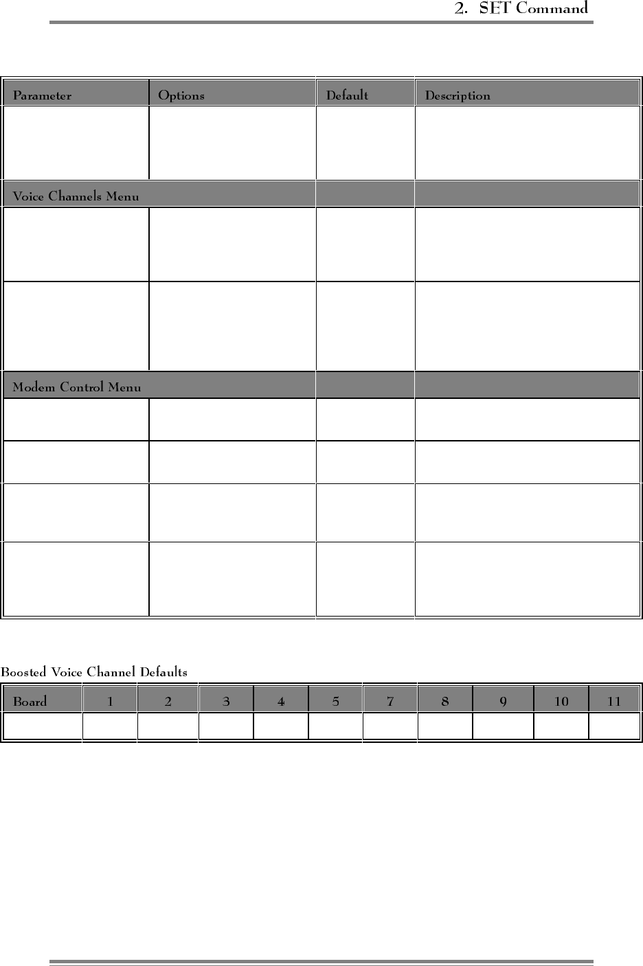
Figure 2-4. System Parameters (Continued)
BOOSTER LINK
CHANNEL -
PREVIOUS EAC
1–799, 991–1023 571 If Multi-hop feature is enabled,
assigns channel used to receive call
setup information from previous EAC
in a Multi-hop configuration.
DONOR VOICE
CHANNEL LIST
Any valid channel and
SAT, up to 105 total
None assigned Voice channels to be scanned for
mobile candidates to be boosted. A
list of channels may be entered for
each of the three SAT frequencies.
BOOSTED VOICE
CHANNELS
1–799, 991–1023 See chart
below*Channels to which the donor voice
channels are translated when a mobile
is being boosted. Should be
consistent with the frequency plan of
the cellular system.
MASTER
PASSWORD
Up to 12 alphanumeric
characters
1234 Used to gain access to system
monitoring and setup commands.
RESTRICTED
PASSWORD
Up to 12 alphanumeric
characters
5678 Used to gain access to system
monitor commands.
CONSOLE TIME-
OUT
10-2500 seconds 300 seconds Maximum time console will wait
before locking during periods of no
keyboard activity.
AUTO-DIAL
ENABLE Armed
Disarmed Disarmed Used to arm/disarm modem's ability
to automatically dial a designated
phone number when critical alarms
exist.
340 361 382 403 424 445 466 487 508 529
Continued . . .
AMPS EAC-2000™ Manual: Vol. 2, Operating Procedures (27-7656-2, 12/95) Page 2-5
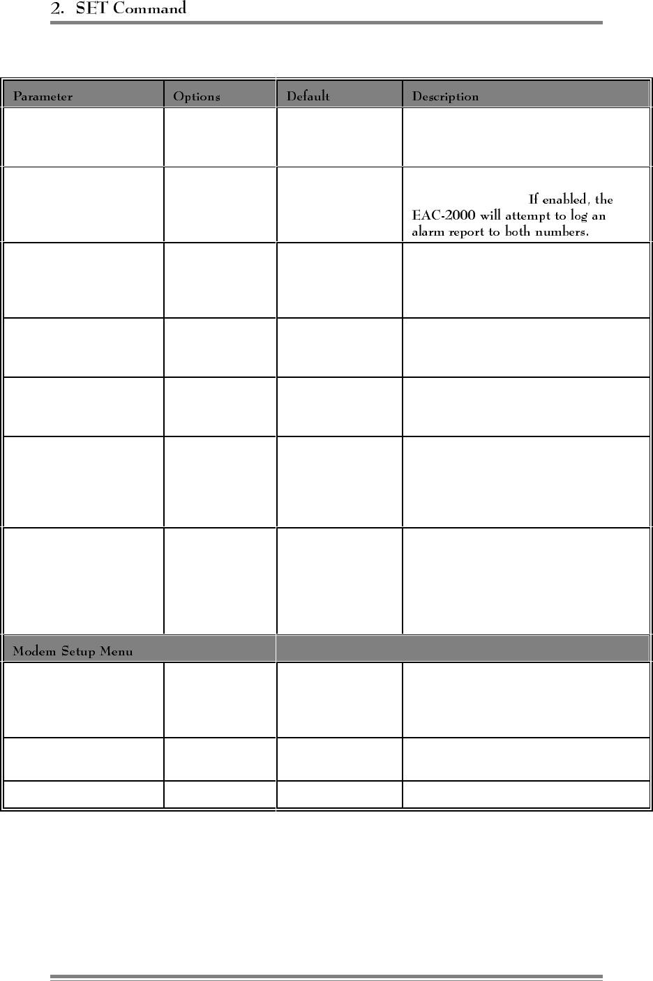
Figure 2-4. System Parameters (Continued)
DIAL-UP PHONE
NUMBER 1 0 (none)
Up to 48
characters
12163498684 Assigns the number to be dialed by the
EAC-2000 when a critical alarm exists.
DIAL-UP PHONE
NUMBER 2
0 (none)
Up to 48
characters
None A second number to be dialed when a
critical alarm exists.
AUTO-DIAL TRIALS
MAX
0-10 10 Maximum number of auto-dial trials the
modem will conduct if there are critical
alarms to be reported and a connection
cannot be made.
DELAY BETWEEN
AUTO-DIAL RETRIES
0-2500 seconds 60 seconds Period the modem will wait after an
unsuccessful auto-dial trial before trying
again.
MAX AUTO-DIAL
TRIAL PERIOD 0-2500 seconds 90 seconds Maximum time modem will wait before
terminating an auto-dial trial if
connection cannot be made.
MODEM MOBILE MIN 10 digits 1234567890 Mobile Identification Number of cellular
mobile booster. Used to identify calls to
and from the remote link; these calls are
not boosted and therefore, do not occupy
a boosted voice channel.
MODEM MOBILE
POWER STEP 0–7 7 Mobile attenuation code (VMAC) for
cellular mobile used to establish remote
link. Power step 0 = full power (3
watts); each additional step = a 4 dB
decrease in power (i.e., step 7 = 28 dB
below full power).
INIT STRING 48 characters AT!~AT!~AT&F
X0E0\D2S0=1
S10=20
)M1:E0*H1!
String of characters sent to modem on
power up and LOC.
DIAL COMMAND 16 characters ATDT String of characters sent to modem prior
to dialing out phone number.
HANGUP STRING 16 characters ~~~+++~~~ATH0!
Continued . . .
Page 2-6 AMPS EAC-2000™ Manual: Vol. 2, Operating Procedures (27-7656-2, 12/95)
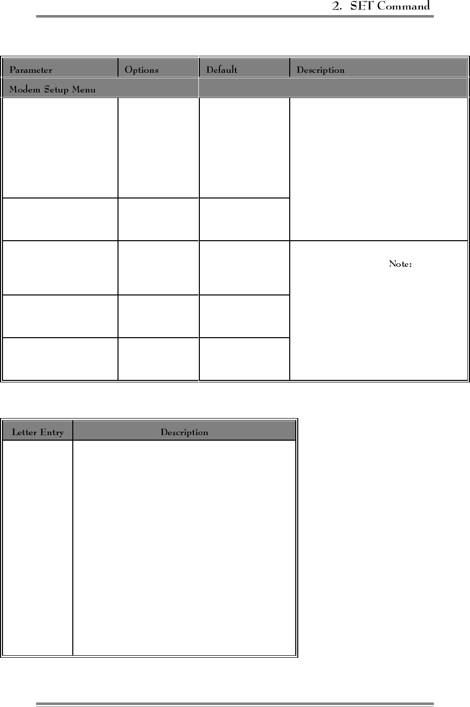
Figure 2-4. System Parameters (Continued)
(Continued)
LOCAL PORT BAUD
RATE
1) 150
2) 300
3) 600
4) 1200
5) 2400
6) 4800
7) 9600
8) 19200
9600 Defines characteristics of ASCII link to
local port.
LOCAL PORT COMM
PARAMETERS
See chart below*7 data, EVEN tx
parity, IGNORE rx
parity, 1 stop
REMOTE PORT BAUD
RATE See list for
LOCAL PORT
BAUD RATE
9600 (Microcomm
modem)
2400 (Millidyne
modem)
Defines characteristics of ASCII link to
modem in EAC-2000. If using a
Microcomm modem, you may access
remote link at any defined speed less
than the setting.
REMOTE PORT COMM
PARAMETERS See chart below*7 data, EVEN tx
parity, CHECK rx
parity, 1 stop
REMOTE PORT
HANDSHAKE
1) None or
XON/XOFF
2) CTS/RTS
CTS/RTS
*Possible Selections for Local and Remote Port Comm Parameters
A
B
C
D
E
F
G
H
I
J
K
L
M
N
O
P
Q
R
7 data, EVEN tx parity, CHECK rx parity, 1 stop
7 data, ODD tx parity, CHECK rx parity, 1 stop
7 data, SPACE tx parity, CHECK rx parity, 1 stop
7 data, MARK tx parity, CHECK rx parity, 1 stop
7 data, EVEN tx parity, IGNORE rx parity, 1 stop
7 data, ODD tx parity, IGNORE rx parity, 1 stop
7 data, SPACE tx parity, IGNORE rx parity, 1 stop
7 data, MARK tx parity, IGNORE rx parity, 1 stop
8 data, NO parity, 1 stop
7 data, EVEN tx parity, CHECK rx parity, 2 stop
7 data, ODD tx parity, CHECK rx parity, 2 stop
7 data, SPACE tx parity, CHECK rx parity, 2 stop
7 data, MARK tx parity, CHECK rx parity, 2 stop
7 data, EVEN tx parity, IGNORE rx parity, 2 stop
7 data, ODD tx parity, IGNORE rx parity, 2 stop
7 data, SPACE tx parity, IGNORE rx parity, 2 stop
7 data, MARK tx parity, IGNORE rx parity, 2 stop
8 data, NO parity, 2 stop
Continued . . .
AMPS EAC-2000™ Manual: Vol. 2, Operating Procedures (27-7656-2, 12/95) Page 2-7

Figure 2-4. System Parameters (Continued)
MOBILE DYNAMIC
POWER CONTROL
THRESHOLD
(0) Disabled
-120 to -20 dBm
-60 dBm Threshold above which the EAC-2000 will
reduce the power of the mobile.
HAND-IN THRESHOLD (0) Disabled
-120 to -20 dBm -90 dBm Signal level threshold at which a mobile on
one of the donor voice channels becomes a
candidate for boosting.
MULTI-DONOR
ACTIVATION THRESHOLD
(0) Disabled
-120 to -20 dBm
(A) Always
Disabled Signal level threshold at which a mobile being
boosted becomes a candidate for hand-off to
an alternate donor cell. (Applicable only if
alternate donor cell has MDU installed.)
HAND-BACK THRESHOLD (0) Disabled
-120 to -20 dBm
-100 dBm Signal level threshold at which a mobile being
boosted becomes a candidate for returning to
original donor voice channel.
HAND-IN MOBILE POWER
STEP
0–7 0 Mobile attenuation code (VMAC) sent to a
mobile being boosted to establish maximum
mobile power level used in boosted coverage
are. Power step 0 = full power (3 watts);
each additional step = 4 dB decrease in power
(i.e., step 7 = 28 dB below full power).
HAND-BACK MOBILE
POWER STEP 0–7 0 Mobile attenuation code (VMAC) sent to a
mobile during a hand-back attempt. This
establishes the power level of the mobiles in
the donor coverage area that have driven from
the booster area with calls in progress. (Same
power step equivalents as above.)
RSSI AVERAGING SPEED Slow
Medium
Fast
Medium Averaging speed for determining when
mobiles become candidates for hand-in or
hand-back.
DELAY BETWEEN HAND-
IN ATTEMPTS
0–250 seconds 5 seconds Amount of time between hand-in attempts on
a mobile identified as a candidate for boosting
(signal exceeds hand-in threshold).
STATION POWER CLASS
SELECTIVE BOOSTING Boost all
Boost I–III
Boost I, II
Boost I
Boost all Allows the EAC-2000 to be configured to
boost only lower-power subscriber units (i.e.,
portables).
Continued . . .
Page 2-8 AMPS EAC-2000™ Manual: Vol. 2, Operating Procedures (27-7656-2, 12/95)
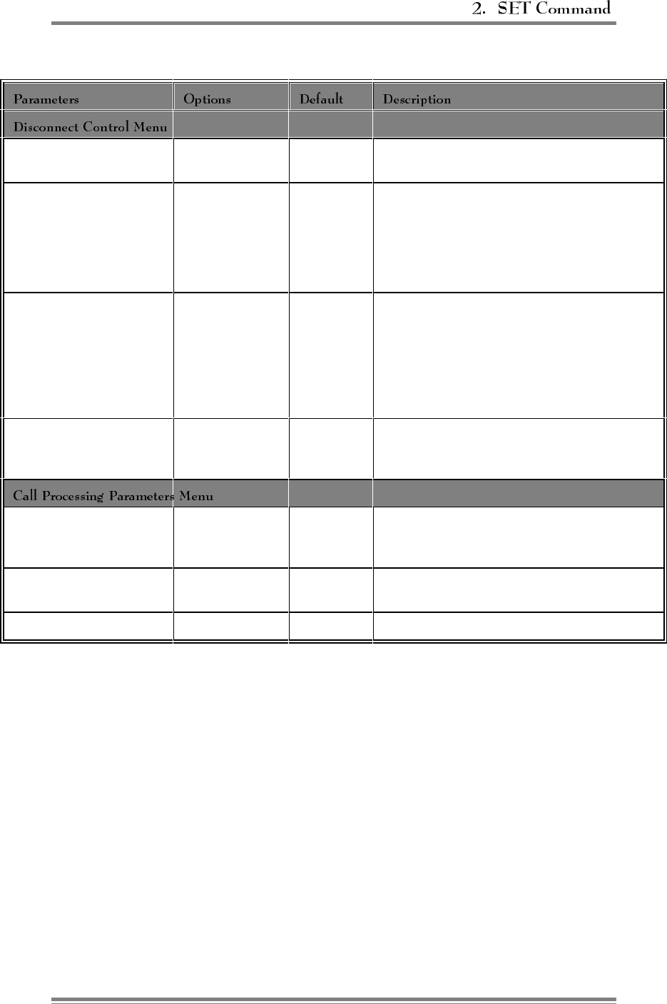
Figure 2-4. System Parameters (Continued)
DONOR RSSI (0) Disabled
-100 to -20 dBm
-80 dBm Threshold below which the EAC-2000 will
disconnect a call.
SAT FADE TIME-OUT 0–250 seconds 5 seconds Time period the system will wait before
terminating an established call when the proper
SAT is not detected from a mobile. (Does not
apply if the mobile sends a release or the
mobile's signal strength falls below the hand-
back threshold.)
MAX NUMBER OF
HAND-BACK
ATTEMPTS PER CALL
0–250 10 Maximum number of hand-back attempts made
on mobiles identified as candidates for hand-
back (signal below hand-back threshold). If
hand-back is not successful before this number
is reached, the booster assumes the mobile is
driving away from the donor cell site and
maintains the call as long as possible.
MINIMUM DELAY
BETWEEN HAND-BACK
ATTEMPTS
0–250 seconds 15 seconds Time between attempts to return the mobile to
the donor channel when it is below the hand-
back threshold.
MOBILE RSSI >
THRESHOLD
PARAMETERS
C1 C1 Conditions for handling mobiles that are above
the hand-in threshold.
HAND-BACK/
GRAB-BACK CONTROL
D1
D2
D1 Conditions under which mobile hand-back
confirmation is treated.
RECOMMENDATIONS On-line recommendations.
AMPS EAC-2000™ Manual: Vol. 2, Operating Procedures (27-7656-2, 12/95) Page 2-9
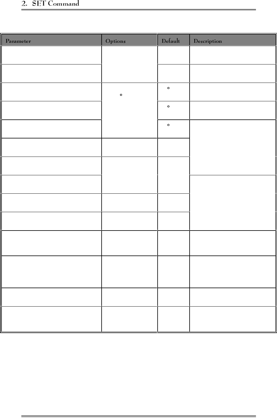
Figure 2-5. Alarm Parameters
ANTENNA RETURN LOSS - LOW
ALARM POINT 0 (Disabled)
1–20 6 dB Define antenna return loss alarm
threshold.
PA TO ANTENNA LOSS - HIGH
ALARM POINT
9 dB Define PA to antenna loss
threshold.
PA TEMP - HIGH ALARM POINT 0 (Disabled)
1–100 C 90 C Defines PA temperature alarm
condition.
PA TEMP - FAN ACTIVATION
POINT
60 C Defines PA temperature that
turns heat exchanger fan on.
PA TEMP - PA POWER CUTBACK
POINT 90 C Define parameters for forward
dynamic power control.
MOBILE POWER CONTROL
CAUSES PA POWER CUTBACK
Enabled
Disabled
Disabled
+28 VOLT SUPPLY - PA POWER
CUTBACK POINT 0 (Disabled)
.1–50.9 Volts 23.0 Volts
+28 VOLT SUPPLY - LOW ALARM
POINT
Alarm thresholds for power
supply voltages
+12 VOLT SUPPLY - LOW ALARM
POINT 0 (Disabled)
.1–14.9 Volts 10.0 Volts
+6 VOLT SUPPLY - LOW ALARM
POINT
0 (Dsiabled)
.1–9.9 Volts
5.4 Volts
EXTERNAL DIGITAL INPUT
ALARM STATE (For each of 8 inputs) (0) Disabled
(1) High
(2) Low
Disabled Defines alarm conditions on the
eight general purpose inputs.
EXTERNAL DIGITAL OUTPUT
CURRENT STATE (For 8 inputs)
(1) High
(2) Low
(3) High if alarm. . .
(4) Low if alarm. . .
Low Defines state of the eight general
purpose outputs.
EXTERNAL ANALOG INPUTS -
ALARM THRESHOLD
0-5 volts 0.0 Vdc Defines alarm condition on the
eight analog inputs.
EXTERNAL ANALOG INPUT -
ALARM STATE
(0) Disabled
(1) Above threshold
(2) Below threshold
Disabled Defines alarm conditions on the
eight analog inputs.
Continued. . .
Page 2-10 AMPS EAC-2000™ Manual: Vol. 2, Operating Procedures (27-7656-2, 12/95)

Figure 2-5. Alarm Parameters (Continued)
CRITICAL ALARMS:
Board Out-of-Service Alarm
Board ROM Alarm
Board Calibration Memory Alarm
Serial Data Link Alarm
Personality Mismatch Alarm
Synthesizer Unlocked Alarm
Reverse PA Power Low Alarm
RSSI Alarm
PA Out-of-Service Alarm
PA Temp - High Alarm
PA Temp - Low Alarm
PA to Antenna High Loss Alarm
Antenna Return Loss Alarm
ROM Alarm
RAM Alarm
NOVRAM Alarm
SAT Detector Alarm
Power Supply Voltages - Low Alarm
External Analog Input Alarm
External Digital Input - Alarms
Log only or
Critical Critical
Critical
Critical
Critical
Critical
Critical
Critical
Log Only
Critical
Log only
Critical
Critical
Critical
Critical
Critical
Critical
Critical
Critical
Log Only
Log Only
"Log only" alarm occurrences
will be logged; total number of
occurrences can be viewed using
the ALA command.
"Critical" alarms will not only be
logged, but also cause the auto-
dial sequence to begin (if
enabled). This sequence
automatically dials a designated
number to report the alarm.
RSSI ALARMS:
Donor Ctrl Chan RSSI Hi Alarm Pt.
Donor Ctrl Chan RSSI Low Alarm Pt.
Donor Voice Chan RSSI Hi Alarm Pt.
(0) Disabled
-100 to -20 dBm Disabled
-80 dBm
Disabled
Establishes alarm levels for these
signals.
AMPS EAC-2000™ Manual: Vol. 2, Operating Procedures (27-7656-2, 12/95) Page 2-11
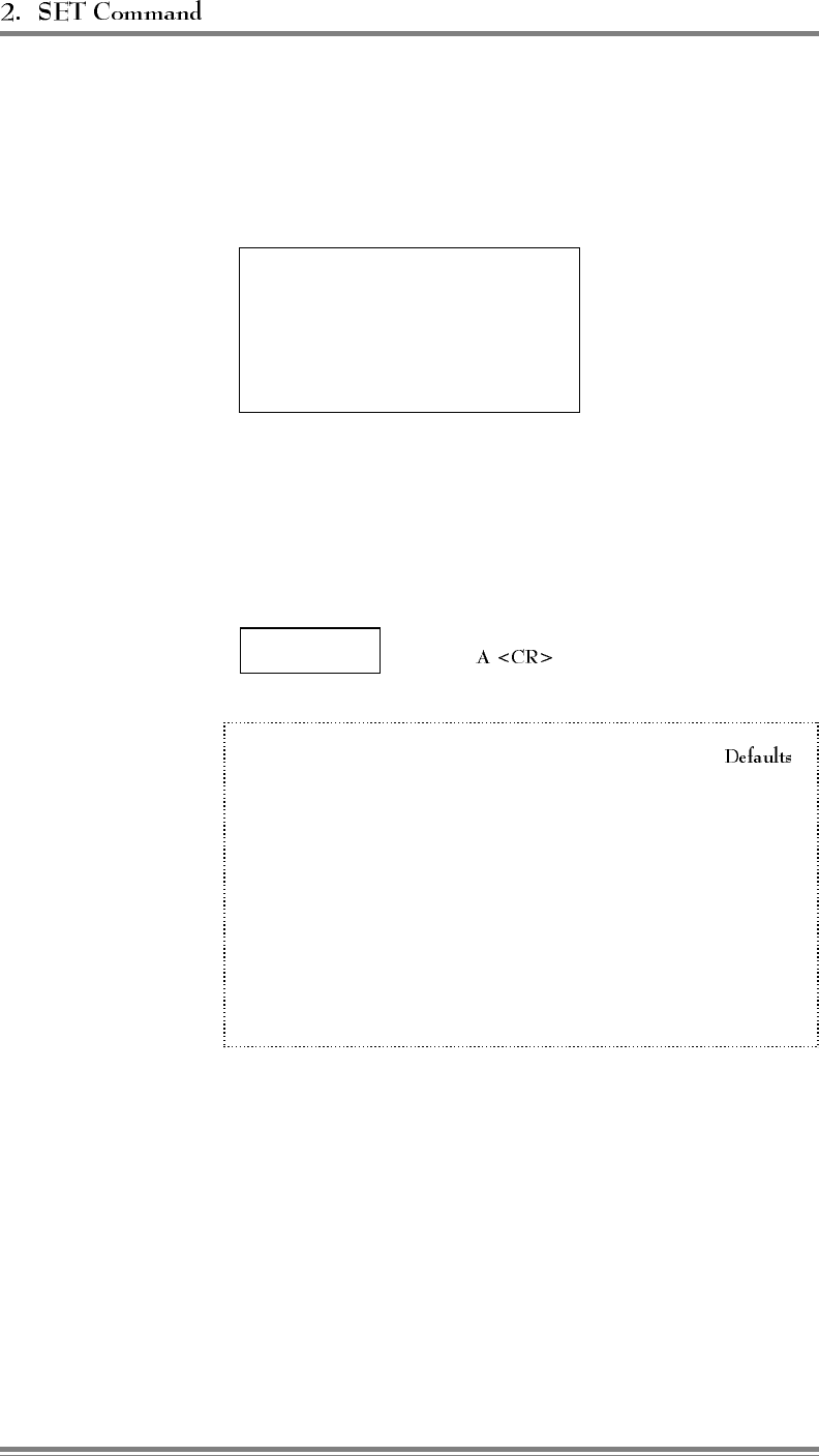
2.2 Main Menu
Entry: At the > prompt, type SET.
ARF Boards
B Power Amplifiers
C System Parameters
DAlarms
E Set Defaults
Menu:
Purpose: Gives access to setup menus.
2.3 RF Boards Menu
Entry:
Main Menu ⇒
Menu:
1 Position 1 ............................ ENABLED
2 Position 2 ............................ ENABLED
3 Position 3 ............................ ENABLED
4 Position 4 ............................ ENABLED
5 Position 5 ............................ ENABLED
6 Position 6 ............................ ENABLED
7 Position 7 ............................ ENABLED
8 Position 8 ............................ ENABLED
9 Position 9 ............................ ENABLED
10 Position 10 ........................... ENABLED
11 Position 11 ........................... ENABLED
Purpose: Shows configuration (type and status) of the 11 RF board positions. From this
menu each board can be selected to access the parameters for that board.
Page 2-12 AMPS EAC-2000™ Manual: Vol. 2, Operating Procedures (27-7656-2, 12/95)
2.3 RF Boards Menu (Continued)
Entry:
Main Menu ⇒RF Boards
Menu ⇒
Menu:
A Status ............................... ENABLED
B Diversity ...........OFF - ANTENNA "M1" SELECTED
Purpose: Gives access to status and diversity parameters.
STATUS
Entry:
Main Menu ⇒RF Boards
Menu ⇒RF Board
Position ⇒
Purpose: To set up the selected RF board.
Options:
• 0 DISABLED: Board ignored by system; not used for boosting; alarms not
logged.
• 1 ENABLED: Reactivates board if it has been taken out of service due to
an alarm. If alarm condition persists, board will go out of service again
when SET is exited. (Default setting)
• 2 NONE: Same as DISABLED. Used to keep track of slots with no
boards installed.
AMPS EAC-2000™ Manual: Vol. 2, Operating Procedures (27-7656-2, 12/95) Page 2-13
(Continued)
DIVERSITY
Entry:
Main Menu ⇒RF Boards
Menu ⇒RF Board
Position ⇒
Purpose: To turn diversity function on or off for reverse paths. Diversity enables
the board to select the best signal between two receive antenna ports, to improve
voice channel performance.
Options:
• 1 DIVERSITY ON: Default for boards 2-5 and 7–11. Not allowed for
board 6.
• 2 OFF—ANTENNA M1 ONLY SELECTED: Positions 1 and 6 default.
• 3 OFF—ANTENNA M2 ONLY SELECTED
2.4 Power Amplifiers Menu
Main Menu ⇒
Menu:
A Forward PA Power Step - Voice ................... 0
B Forward PA Power Step - Control .................. 0
C Forward PA Power Step - Hand-off ................. 0
D Forward PA Power Low Alarm Point - Voice .....+40 dBm
E Forward PA Power Low Alarm Point - Control....+40 dBm
F Forward PA Power Low Alarm Point - Hand-off . . . +40 dBm
G Reverse PA Power Set - Voice ...............+20 dBm
H Reverse PA Power Set - Control ..............+20 dBm
I Reverse PA Power Low Alarm Point - Voice .....+15 dBm
J Reverse PA Power Low Alarm Point - Control ....+15 dBm
K Key Forward PA .... POWER ADJ/COMBINER TUNING
L Key Reverse PA ............POWER MEASUREMENT
Purpose: Shows configuration of the PAs.
Page 2-14 AMPS EAC-2000™ Manual: Vol. 2, Operating Procedures (27-7656-2, 12/95)
2.4 Power Amplifiers Menu (Continued)
FORWARD PA POWER STEP - VOICE
FORWARD PA POWER STEP - CONTROL
FORWARD PA POWER STEP - HAND-OFF
Entry:
Main Menu ⇒Power Amplifiers
Menu ⇒, , or
Purpose: These three parameters are used to select the power step for:
• Voice channel PAs
• Control channel PA
• Hand-off PA
Options:
• Steps: 0–3
–0 is full power (45 watts); each step is a 4 dB decrease in power.
• Default: 0
FORWARD PA POWER LOW ALARM POINT - VOICE
FORWARD PA POWER LOW ALARM POINT - CONTROL
FORWARD PA POWER LOW ALARM POINT - HAND-OFF
Entry:
Main Menu ⇒Power Amplifiers
Menu ⇒, , or
Purpose: These three parameters are used to set low power alarm threshold for forward
voice PAs. Should be 5 to 6 dB below power read using "key forward." Voice PA alarms
cause the PA to be taken out of service and hand-off PA alarms to be logged, but the PA
remains in service. If the Backup Control Channel option (see Sec. 2.5.2) is enabled, a low
PA power on the control channel will cause out-of-service for that PA.
Options:
• Range: 0, 30–50
• Default: +40 dBm
REVERSE PA POWER SET - VOICE
REVERSE PA POWER SET - CONTROL
Main Menu ⇒Power Amplifiers
Menu ⇒ or
Purpose: These two parameters are used to select power level for reverse PAs.
Options:
• Range: +5 to +20 dBm
• Default: +20 dBm
AMPS EAC-2000™ Manual: Vol. 2, Operating Procedures (27-7656-2, 12/95) Page 2-15
2.4 Power Amplifiers Menu (Continued)
REVERSE PA POWER LOW ALARM POINT - VOICE
REVERSE PA POWER LOW ALARM POINT - CONTROL
Entry:
Main Menu ⇒Power Amplifiers
Menu ⇒ or
Purpose: These two parameters are used to set low power alarm threshold for reverse PAs.
Should be 5 dB below power read using "key reverse."
Options:
• Range: 0, 1–23
• Default: +15 dBm
KEY FORWARD PA
Main Menu ⇒Power Amplifiers
Menu ⇒
Purpose: To key forward PA.
Options:
• PAs 1–11; position of PA to key. Keys PA on boosted channel at step as entered in A,
B and C. Displays position channel number and continuously updated PA power reading
at PA output.
KEY REVERSE PA
Main Menu ⇒Power Amplifiers
Menu ⇒
Purpose: Keys reverse PA for reverse power monitoring. Output channel is 10 channels
below boosted channel. Ouput level is as defined in J and K.
Note: Board 6 uses the "CNTL" setting.
Page 2-16 AMPS EAC-2000™ Manual: Vol. 2, Operating Procedures (27-7656-2, 12/95)
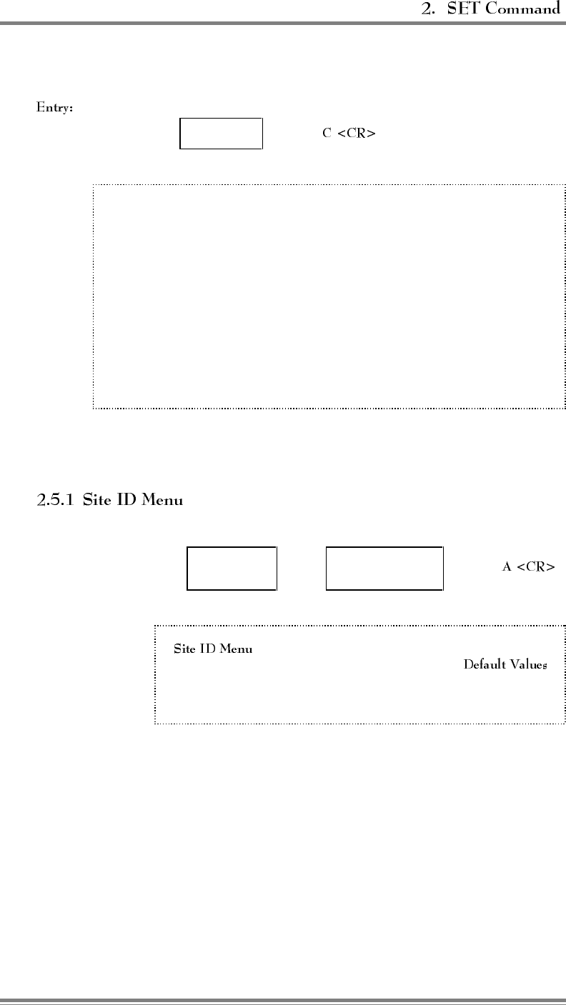
2.5 System Parameters Menu
Main Menu ⇒
Menu:
A Site ID.........Identification Multi-Hop
B Control Channels . Donor Boosted State
C Voice Channels . . . Donor Donor SAT Boosted
D Modem Control . . . Passwords Console Time-out
Auto-dial Control
Dial-up Phone Modem Mobile
E Thresholds ......Hand-in Hand-back Multi-Donor
Mobile Power RSSI Averaging Hand-in Delay
F Disconnect Control Donor RSSI SAT Fade Time-out
Hand-back Delay Hand-back Attempts
G Call Processing . . . Mobile Orig Mobile Answer
RSSI > Thresh Hand-back / Grab-back
Purpose: Displays parameters associated with overall system.
Entry:
Main Menu ⇒System
Parameters Menu ⇒
Menu:
A Site Identification......................Not Assigned
B Multi-hop Feature ......................DISABLED
Purpose: Gives access to parameters associated with site ID.
AMPS EAC-2000™ Manual: Vol. 2, Operating Procedures (27-7656-2, 12/95) Page 2-17
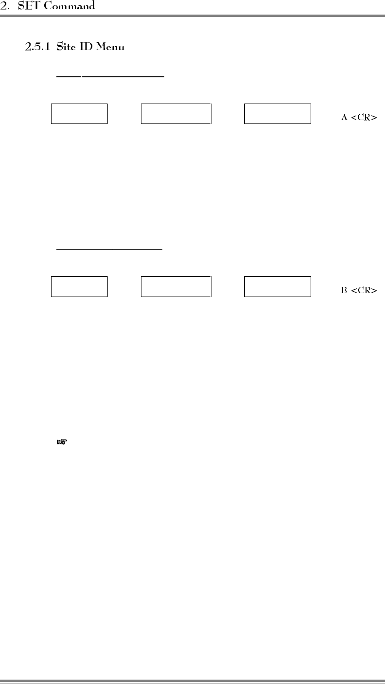
(Continued)
SITE IDENTIFICATION
Entry:
Main Menu ⇒Sys. Par. Menu ⇒Site ID Menu ⇒
Purpose: To assign/modify a name that uniquely identifies the site. Name appears
on console when the remote/local link is established to identify the site with which
the user is communicating.
Options:
• Allowable entries: Any string of up to 20 characters
• Default: Not assigned
MULTI-HOP FEATURE
Entry:
Main Menu ⇒Sys. Par. Menu ⇒Site ID Menu ⇒
Purpose: To turn the Multi-hop feature on or off.
Options:
• 0= DISABLED: Default setting; causes conventional stand-alone operation.
• 1= ENABLED - MODE 1 - ADJACENT TO DONOR
• 2= ENABLED - MODE 2 - ADJACENT TO AN EAC-2000
• 3= ENABLED - MODE 3 - ADJACENT TO AN EAC-IV (NO PRIOR
EAC-2000 IN CHAIN)
• 4= ENABLED - MODE 4 - ADJACENT TO AN EAC-IV (WITH PRIOR
EAC-2000 IN CHAIN)
NOTE: The EAC-2000 may be used in a Multi-hop configuration with other
EAC-2000s and/or Extend-A-Cell® IVs. The type of units between the EAC-
2000 and the donor will determine how this option should be set.
Page 2-18 AMPS EAC-2000™ Manual: Vol. 2, Operating Procedures (27-7656-2, 12/95)
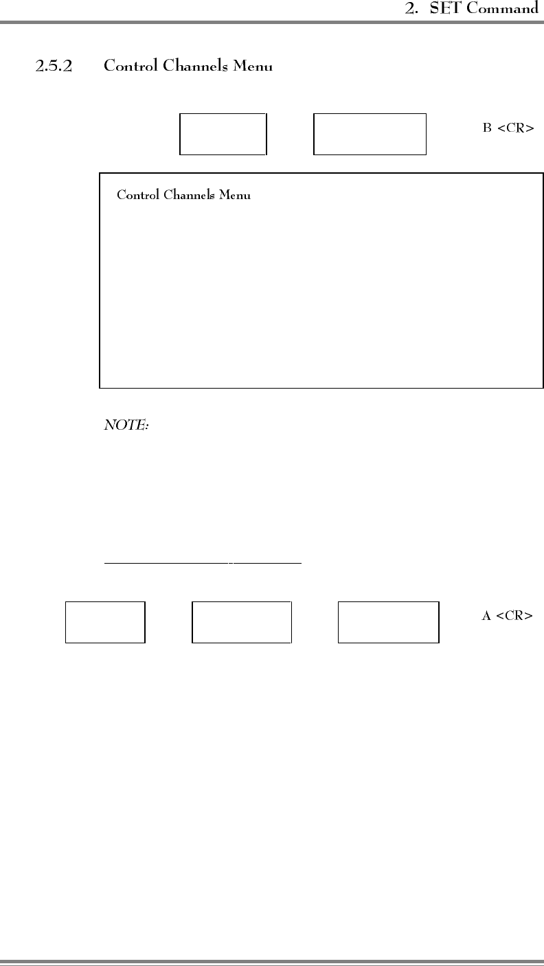
Entry:
Main Menu ⇒System
Parameters Menu ⇒
Menu:
A Donor Control Channel ............................... 337
B Boosted Control Channel ............................. 340
C RF Board to Use for Control Channel ...................... 1
D Control Channel State During "All Channels Busy DIRECTED RETRY
E Directed Retry Channels ............................. LIST
F Back-up Control Channel Option ...................DISABLED
G Revertive Control Channel Option ..................DISABLED
H Substitute Control Channel .......................DISABLED
I Booster Link Channel................................ 550
J Booster Link Channel - Previous EAC .................... 571
Selection H appears only if Selection F or G is set to ENABLED.
Selection I appears only if the Multi-Donor Threshold is not DISABLED.
Selection J appears only if the Multi-hop Feature is set to Mode 3 or Mode 4.
Purpose: Gives access to donor and boosted control channels, for entering
channel numbers.
DONOR CONTROL CHANNEL
Entry:
Main Menu ⇒Sys. Par. Menu ⇒Control
Channels Menu ⇒
Purpose: To establish the donor control channel number.
Options:
• Allowable range: 1–799, 991–1023
• Default: 337
EAC-2000™ Manual: Vol. 2, Operating Procedures (27-7926-2, 12/95) Page 2-19
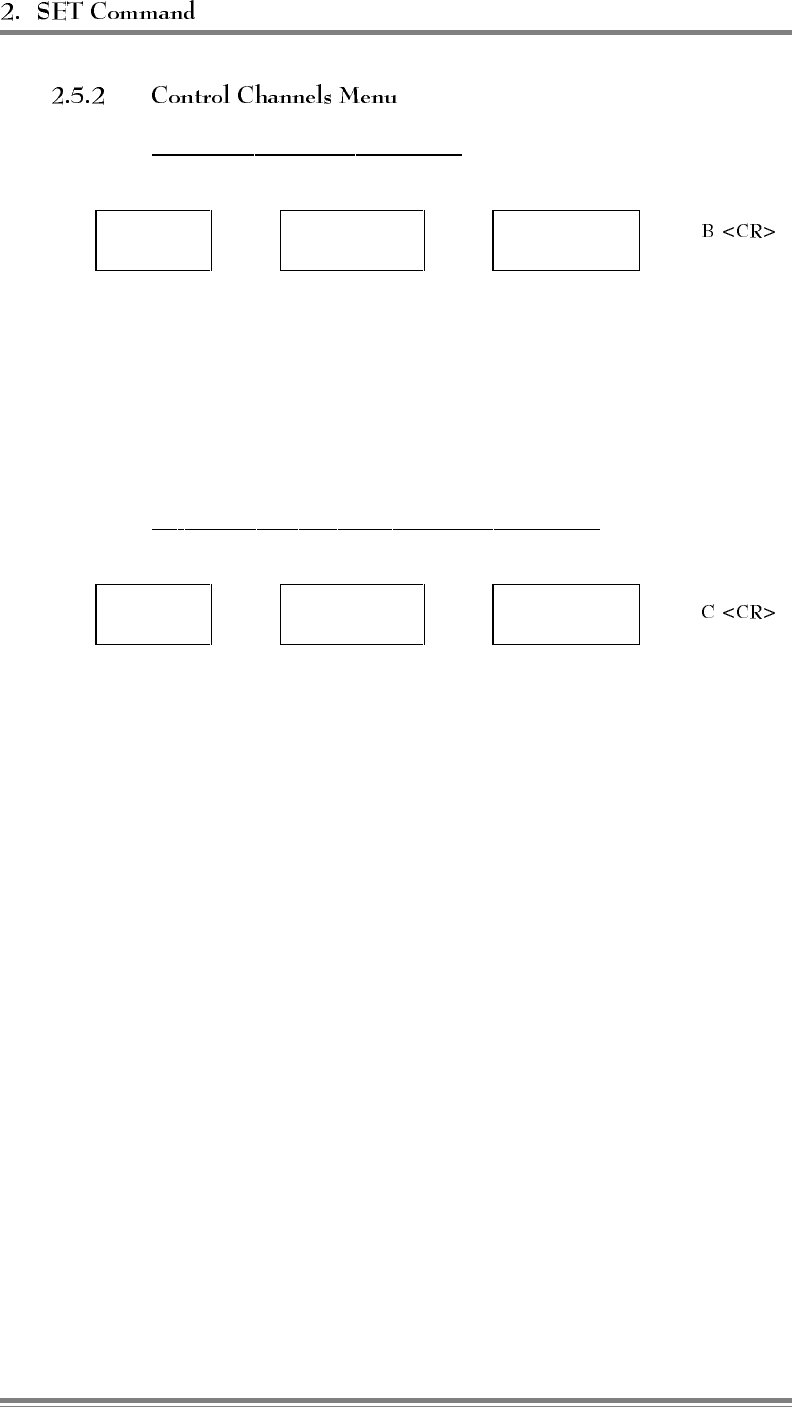
(Continued)
BOOSTED CONTROL CHANNEL
Entry:
Main Menu ⇒Sys. Par. Menu ⇒Control
Channels Menu ⇒
Purpose: To establish the boosted control channel number. This is the channel
to which combiner port 1 is tuned. Any changes to this parameter will
necessitate retuning the combiner.
Options:
• Allowable range: 1–799, 991–1023
• Default: 340
RF BOARD TO USE FOR CONTROL CHANNEL
Entry:
Main Menu ⇒Sys. Par. Menu ⇒Control
Channels Menu ⇒
Purpose: To assign one of the RF boards to boost the control channel.
Options:
• 0 VOICE CHANNELS ONLY: All channels will operate as voice
channels only. Appropriate only in a multi-cabinet configuration
of EAC-2000s for the units not boosting the control channel.
(Presumably, another EAC-2000 would be set up to boost the
control channel.)
• 1–11 CORRESPONDING RF BOARD POSITION: Allows assignment
of one of the RF boards (except board 6) to boost the control
channel. The associated combiner port should be tuned to the
Boosted Control Channel.
• Default: 1
Page 2-20 EAC-2000™ Manual: Vol. 2, Operating Procedures (27-7926-2, 12/95)
(Continued)
CONTROL CHANNEL STATE DURING "ALL CHANNELS BUSY"
Entry:
Main Menu ⇒Sys. Par. Menu ⇒Control
Channels Menu ⇒
Purpose: To establish the state of the boosted control channel when all boosted
voice channels are occupied.
Options:
• OFF: The best option for installations where there is no competing
service. Boosted control channel will be taken down during periods when
no voice channels are available for processing new calls. When the EAC-
2000 becomes busy, mobiles that are in the boosted coverage area (but
not on a call) will rescan and lock onto another control channel (possibly
a competitor's).
• BOOST ACCESSES: Use only if there is good coverage from the donor
cell in the booster coverage area. The boosted control channel will stay
up when all boosted voice channels are busy. Mobiles in the coverage
area will remain locked to the boosted control channel. If a call is
attempted while the EAC-2000 is busy, the call setup transmissions on the
control channel will be boosted. However, the EAC-2000 will not boost
the call on the voice channel, and the mobile will be left on the original-
donor-assigned voice channel. Thus the call will be set up but, if the
mobile is unable to communicate with the donor directly, the call will
drop.
• DENY ACCESSES: Forward boosted control channel will stay up, but
the reverse control boost path will be disabled. Therefore mobiles in the
booster coverage area will remain locked to the boosted control channel,
but if they try to place or answer a call they will be unable to signal back
to the donor on the reverse control channel. Mobiles' attempted call will
result in "fast busy" (reorder) at the mobile within about 1 second. Calls
to a mobile in a busy EAC-2000 coverage area will result in a "mobile
not in service area" message to the calling party.
• DENY ACCESSES, BUT COUNT: This is similar to "Deny Access";
the mobile is allowed to access the EAC-2000, but the access is not
repeated. This allows the call attempt to be logged. Mobile calls will
result in fast busy after about 5 seconds.
• DIRECTED RETRY: Default setting. Probably the best option for
installations where a competitive system exists. When the EAC-2000 is
busy, the boosted channel stays on the air. If more accesses or page
responses come in, the EAC-2000 sends the mobile a special "directed
retry" message. This message gives the mobile a list of up to six other
control channels on which to attempt the access. These directed retry
channels can be set by the user.
EAC-2000™ Manual: Vol. 2, Operating Procedures (27-7926-2, 12/95) Page 2-21
(Continued)
DIRECTED RETRY CHANNELS
Entry:
Main Menu ⇒Sys. Par. Menu ⇒Control
Channels Menu ⇒
Purpose: If the control channel state is set to this mode, this list of six
channels will be sent to the mobile in the directed retry message. The mobile
will scan this set of channels and will try its access on the strongest of the six
channels. The donor control channel and the control channel of cells adjacent
to the boosted coverage should be entered.
NOTE: The boosted control channel must not be in this list.
Options:
• Any valid channel
• Default: All disabled
BACK-UP CONTROL CHANNEL OPTION
Entry:
Main Menu ⇒Sys. Par. Menu ⇒Control
Channels Menu ⇒
Purpose: If enabled, board 6 will be used to boost the control channel if the
normal control channel board is disabled, either by the user or by an alarm.
Boosted channel will be the "Substitute Control Channel."
Options:
• Enabled
• Disabled (default)
Page 2-22 EAC-2000™ Manual: Vol. 2, Operating Procedures (27-7926-2, 12/95)
(Continued)
REVERTIVE CONTROL CHANNEL OPTION
Entry:
Main Menu ⇒Sys. Par. Menu ⇒Control
Channels Menu ⇒
Purpose: If enabled, board 1, or whichever board is assigned to boost the
control channel, will be used to boost the last call.
Options:
• Enabled
• Disabled (default)
SUBSTITUTE CONTROL CHANNEL
Entry:
Main Menu ⇒Sys. Par. Menu ⇒Control
Channels Menu ⇒
Purpose: To assign a control channel for use by board 6 when the control
channel equipment is disabled or is being used to boost the last voice call
Options:
• DISABLED: Default setting.
• Allowable range: 1–799, 991–1023
Use board 6 to boost the control channel onto the channel chosen in the
following situations:
• if the revertive control channel feature is enabled and the control channel
equipment is used to boost the last call; or
• if the backup control channel feature is enabled and the control channel
equipment is disabled (i.e., due to low PA power).
The substitute control channel number must be from the set of dedicated control
channels. The substitute control channel must be separated from the donor
control channel by at least three channels (90 kHz). If the revertive control
channel option is enabled, the substitute control channel must also be separated
from the boosted control channel by at least three channels (90 kHz).
If the revertive control channel option is disabled and the back-up control
channel option is enabled, the substitute control channel may be the same as the
boosted control channel. Since board 6 is used to transmit the substitute control
channel and since its output is not combined, the combiner tuning is not affected
by this channel choice.
EAC-2000™ Manual: Vol. 2, Operating Procedures (27-7926-2, 12/95) Page 2-23
(Continued)
NOTE: Interaction of Revertive Control Channel Option, Substitute Control
Channel, and Boosted Control Channel State When All Channels Busy:
If the Revertive Control Channel Option is enabled, then "All Channels Busy"
occurs when the control channel board is boosting the last call. Therefore, the
"Boosted Cntl Channel State When All Channels Busy" actually applies to board
6 when it is acting as the substitute cntl channel.
For example, if "State" is set to Disabled, then board 6 will not be brought up as
a substitute cntl channel even though it might otherwise be enabled. If "State" is
set to Directed Retry, board 6 will be used to send those messages.
BOOSTER LINK CHANNEL
Entry:
Main Menu ⇒Sys. Par. Menu ⇒Control
Channels Menu ⇒
Purpose: To identify the dedicated link channel used to signal between an
EAC-2000 and any listening EAC-2000s or EAC-IVs in a Multi-hop
configuration.
Options:
• Must be selected if:
- Multi-hop Feature is enabled.
• Allowable range: 1–799, 991–1023
BOOSTER LINK CHANNEL—PREVIOUS EAC
Entry:
Main Menu ⇒Sys. Par. Menu ⇒Control
Channels Menu ⇒
Purpose: Identifies the dedicated link channel used to receive call setup
information from the previous EAC-IV in a Multi-hop configuration (only
appears if Multi-hop feature is set to Mode 3 or 4).
Options:
• Allowable range: 1–799, 991–1023
• Set parameter to channel assigned as booster link channel in the previous
EAC-IV in a Multi-hop chain.
Page 2-24 EAC-2000™ Manual: Vol. 2, Operating Procedures (27-7926-2, 12/95)
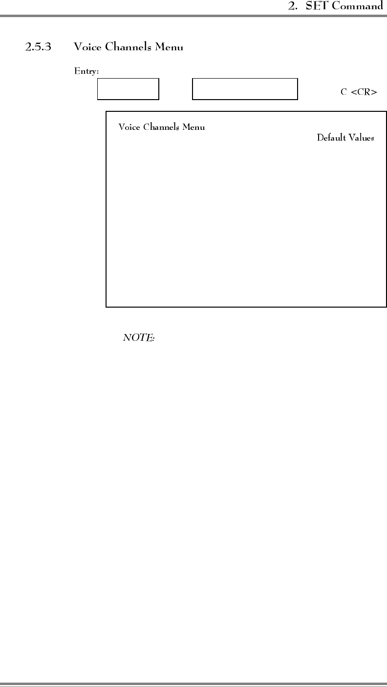
Main Menu ⇒System Parameters Menu ⇒
Menu:
A Donor Voice Channels (5970 Hz SAT) .............List
B Donor Voice Channels (6000 Hz SAT) .............List
C Donor Voice Channels (6030 Hz SAT) .............List
M Donor Voice Channels (Multiple SAT) ..............List
2 Boosted Voice Channel Position 2 .................361
3 Boosted Voice Channel Position 3 .................382
4 Boosted Voice Channel Position 4 .................403
5 Boosted Voice Channel Position 5 .................424
7 Boosted Voice Channel Position 7 .................445
8 Boosted Voice Channel Position 8 .................466
9 Boosted Voice Channel Position 9 .................487
10 Boosted Voice Channel Position 10 ................508
11 Boosted Voice Channel Position 11 ................529
Selection 1, Boosted Voice Channel 1, is displayed only
if the "Voice Channels Only" state is selected for "RF Board to Use
for Control Channel" on Control Channel Menu..
Purpose: Gives access to donor voice channel lists and boosted voice channels.
EAC-2000™ Manual: Vol. 2, Operating Procedures (27-7926-2, 12/95) Page 2-25

(Continued)
DONOR VOICE CHANNEL LISTS (5970–6030 Hz SAT)
Entry:
Main Menu ⇒Sys. Par. Menu ⇒Voice Channels
Menu ⇒, , or
Purpose: To display/change the list of donor voice channels, for the
corresponding SAT, which are scanned for mobile candidates to boost. When
scanned, a candidate is verified as having the correct SAT before being boosted.
Once the call is set up, the appropriate SAT is monitored.
Allowable Range:
• 1–799, 991–1023
Making Entries:
• Enter a given channel in only one list.
• Entering channels in lists:
- To add a channel: enter A [channel number] <CR>.
- To add 15 channels spaced 48 channels apart, precede channel
number with +. Remove unwanted channels.
- To remove a channel, enter R [channel number] <CR>.
- To add/remove multiple channels: enter A (add) or R (remove)
[multiple channel numbers separated by commas or spaces] <CR>.
• To change the SAT of a given channel, remove the channel from the old
SAT list, then add the channel to the new SAT list.
Page 2-26 EAC-2000™ Manual: Vol. 2, Operating Procedures (27-7926-2, 12/95)
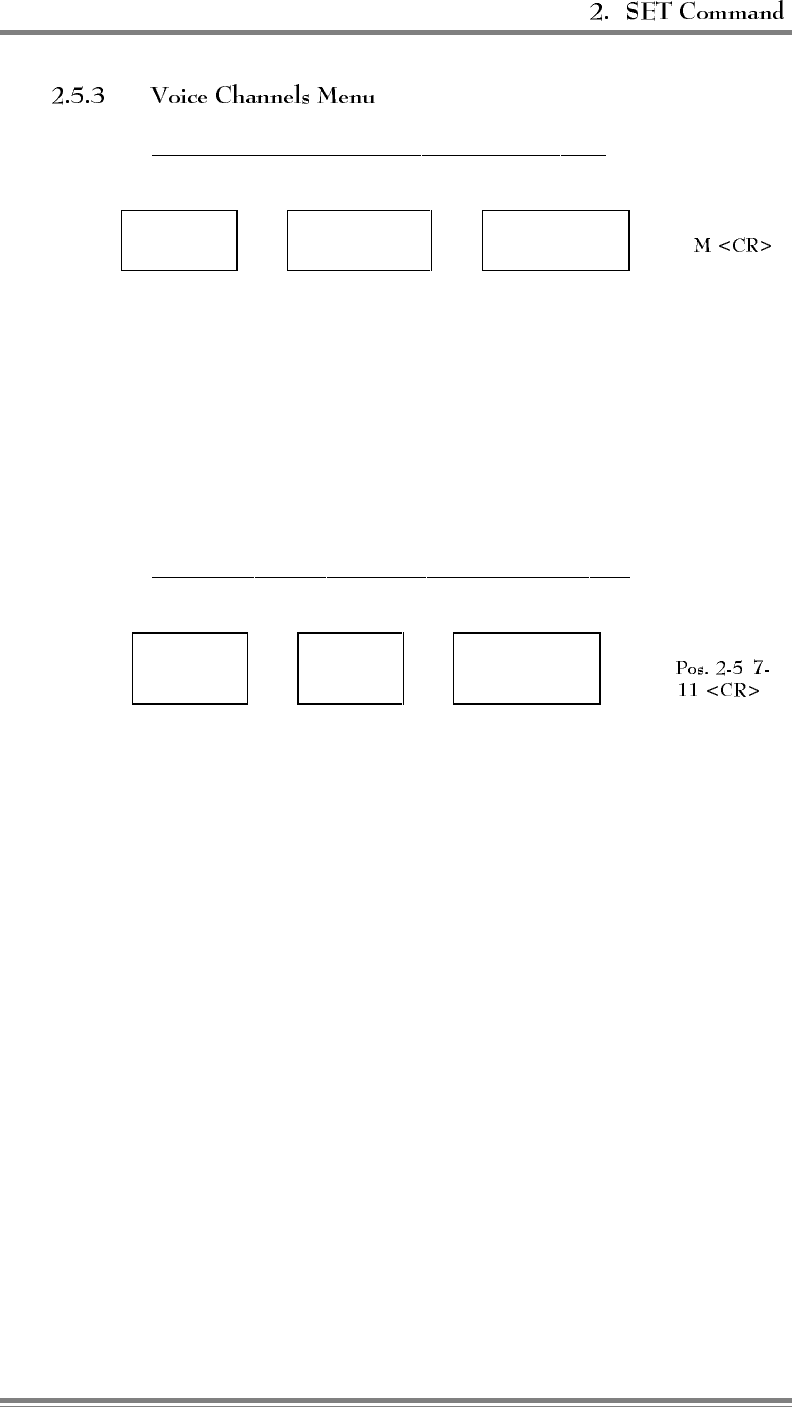
(Continued)
DONOR VOICE CHANNELS LIST (Multiple SAT)
Entry:
Main Menu ⇒Sys. Par. Menu ⇒Voice Channels
Menu ⇒
Purpose: To display and/or change the list of donor voice channels for use in
a Multi-hop. This parameter is needed when a call may be boosted on various
boosted channels (with different SATs) of the previous EAC-2000, depending
on which donor originally set up the call.
Enter channels in this list ONLY when—
• The EAC-2000 is one of the Multi-hop units (not adjacent to primary
donor cell).
• One of the previous EAC-2000s in the chain has multiple possible donors.
BOOSTED VOICE CHANNEL POSITIONS 2–5, 7–11
Entry:
Main Menu ⇒Sys. Par.
Menu ⇒Voice Channels
Menu ⇒,
Purpose: To assign boosted voice channels.
Options:
• Allowable range: 1–799, 991–1023
NOTE:
• "Boosted voice channel 1" appears if RF board to use for control channel
is set to 0.
• When boosted voice channels 2–5 and 7–11 are entered, the associated
combiners must be retuned.
EAC-2000™ Manual: Vol. 2, Operating Procedures (27-7926-2, 12/95) Page 2-27
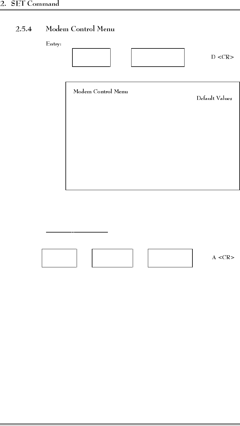
Main Menu ⇒System Parameters
Menu ⇒
Menu:
A Master Password ............................1234
B Restricted Password ..........................5678
C Console Time-out..................... 30 (x 10 Sec)
D Auto-dial Enable ...................... DISARMED
E Dial-up Phone Number 1 ................12163498684
F Dial-up Phone Number 2 .................... NONE
G Auto-dial Trials Max .......................... 10
H Delay Between Auto-dial Retries ........... 6 (x 10 Sec)
I Max Auto-dial Trial Period ............... 9 (x 10 Sec)
J Modem Setup ...................... PARAMETERS
K Modem Mobile MIN ....................1234567890
L Modem Mobile Power Step....................... 7
Purpose: Gives access to parameters associated with EAC-2000’s remote link
modem.
MASTER PASSWORD
Entry:
Main Menu ⇒Sys. Par.
Menu ⇒Modem Control
Menu ⇒
Purpose: To assign a master password unique to the site. When entered in
response to a password prompt, it unlocks the console unconditionally and
allows access to all system setup and monitor commands.
Options:
• Allowable entries: Any string of up to 12 characters
• Default: 1234
Page 2-28 EAC-2000™ Manual: Vol. 2, Operating Procedures (27-7926-2, 12/95)
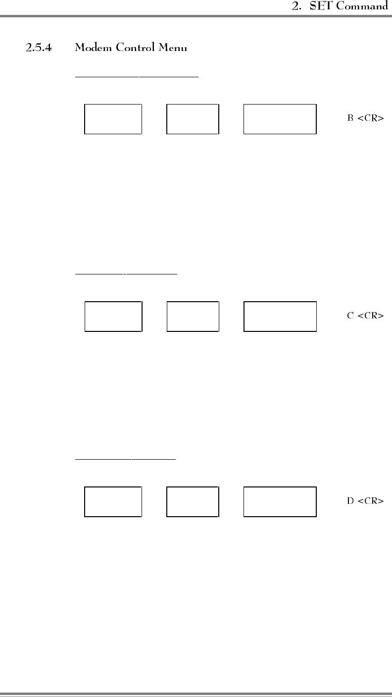
(Continued)
RESTRICTED PASSWORD
Entry:
Main Menu ⇒Sys. Par.
Menu ⇒Modem Control
Menu ⇒
Purpose: To assign a unique restricted password for the site. When entered
in response to a password prompt, it unlocks the console but only allows the
user access to the following system monitoring commands: ALA, HEL, LOC,
RSS, SSS, DCH, DCS, SSR, and SCS.
Options:
• Allowable entries: Any string of up to 12 characters
• Default: 5678
CONSOLE TIME-OUT
Entry:
Main Menu ⇒Sys. Par.
Menu ⇒Modem Control
Menu ⇒
Purpose: To set the maximum time the console will wait before locking during
periods of no keyboard activity.
Options:
• Displayed in multiples of 10 seconds
• Allowable range: 1–250 (10–2500 seconds)
• Default: 30 (300 seconds, or 5 minutes)
AUTO-DIAL ENABLE
Entry:
Main Menu ⇒Sys. Par.
Menu ⇒Modem Control
Menu ⇒
Purpose: To arm/disarm the modem's ability to automatically dial a designated
telephone number when critical alarms exist.
Options:
•ARMED
• DISARMED (default)
NOTE: This function automatically disarms after a successful auto-dial (to
prevent duplicate alarm reporting) or after the designated maximum number of
auto-dial trials have been made without a successful connection.
EAC-2000™ Manual: Vol. 2, Operating Procedures (27-7926-2, 12/95) Page 2-29
(Continued)
DIAL-UP PHONE NUMBERS (1 AND 2)
Entry:
Main Menu ⇒Sys. Par.
Menu ⇒Modem Control
Menu ⇒
Purpose: To assign numbers to be dialed by the EAC-2000 when a critical
alarm condition occurs. The second dial-up phone number is typically used to
alert a different location.
NOTE: If both numbers are entered, the EAC-2000 will alternately dial
both until a successful connection is made and a report is transmitted.
The EAC-2000 will continue dialing until a successful connection is made
and a report is transmitted to both numbers.
Options:
• Allowable entries: Any string of up to 48 characters. The following
special entries allow user to specify non-displayable characters and EAC
delays in string:
~
!
^@-^_
^1-^9
^~
^!
^^
causes EAC to delay .5 seconds
causes EAC to send an ASCII 0D hex (carriage return)
causes EAC to send non-displayable control characters
causes EAC to delay 1–9 seconds
causes EAC to send an ASCII 7E hex ("~" character)
causes EAC to send an ASCII 21 hex ("!" character)
causes EAC to send an ASCII 5E hex ("^" character)
NOTE: This allows any ASCII character 1–7E to be specified.
• Default:
–Dial-Up Phone #1: 12163498684 (Allen Telecom Systems, Systems
Engineering Department)
–Dial-Up Phone #2: None
Page 2-30 EAC-2000™ Manual: Vol. 2, Operating Procedures (27-7926-2, 12/95)
(Continued)
DIAL-UP PHONE NUMBERS (1 AND 2) (Continued)
EAC delays (specified by ~ and ^1 – ^9) cause the EAC to delay the specified
time before sending more characters (no characters are sent to the modem
during the delay time). This is not to be confused with "modem" delay
characters, which are actually sent to the modem, where the delay occurs.
Hayes compatible uses "," to specify a "pause" delay, which defaults to 2
seconds.
For example—
• Use ~ to give the modem time to process a command string; i.e., the ~ in
"~~~+++~~~ATH0!", the default hang-up string, specifies the 1.5 second delay
before and after the "+++" needed to guarantee a modem will enter
"command" mode.
• Use "," to specify dialing delays; i.e., in a dial string, "5493857,,,,1234"
specifies that the modem should dial 5493857, delay 8 seconds, then dial
1234. This might be used to dial a number, wait for an answer, then
overdial more digits (for example, a paging service).
AUTO-DIAL TRIALS MAX
Entry:
Main Menu ⇒Sys. Par.
Menu ⇒Modem Control
Menu ⇒
Purpose: To set the maximum number of auto-dial trials the modem will
attempt if there are critical alarms to be reported and a connection cannot be
made.
Options:
• Allowable range: 0–10 attempts
• Default: 10 attempts
EAC-2000™ Manual: Vol. 2, Operating Procedures (27-7926-2, 12/95) Page 2-31
(Continued)
DELAY BETWEEN AUTO-DIAL RETRIES
Entry:
Main Menu ⇒Sys. Par.
Menu ⇒Modem Control
Menu ⇒
Purpose: To set the length of time the modem will wait after an unanswered
auto-dial call (critical alarm report) before trying again.
Options:
• Displayed in multiples of 10 seconds
• Allowable range: 0–250 (0–2500 seconds)
• Default: 6 (60 seconds)
MAX AUTO-DIAL TRIAL PERIOD
Entry:
Main Menu ⇒Sys. Par.
Menu ⇒Modem Control
Menu ⇒
Purpose: To set the maximum length of time the modem will wait before
disconnecting an unanswered auto-dial call.
Options:
• Displayed in multiples of 10 seconds
• Allowable range: 0–250 (0–2500 seconds)
• Default: 6 (60 seconds)
Page 2-32 EAC-2000™ Manual: Vol. 2, Operating Procedures (27-7926-2, 12/95)
(Continued)
MODEM SETUP
Entry:
Main Menu ⇒Sys. Par.
Menu ⇒Modem Control
Menu ⇒
Menu:
A Init String ............. AT!~AT!~AT&FX0E0\D2S0=1S10=20)M1:E0*H1!
B Dial Prefix String........................................ ATDT
C Hangup String ..................................~~~+++~~~ATH0!
D Local Port Baud Rate ...................................... 9600
E Local Port Comm Params . . . 7 data, EVEN tx parity, IGNORE rx parity, 1 stop
F Remote Port Baud Rate .................................... 9600
G Remote Port Comm Params . . 7 data, EVEN tx parity, CHECK rx parity, 1 stop
H Remote Port Handshake ................................. CTS/RTS
Purpose: Gives access to parameters associated with setting up the modem.
INIT STRING
Entry:
Main
Menu ⇒Sys. Par.
Menu ⇒Modem
Control Menu ⇒Modem
Setup Menu ⇒
Purpose: To specify the string used to initialize the modem. This string is sent
at power-up and after LOC or console timeout; changes will be effective for the
next session.
Options:
• Allowable entries: Any string of up to 48 characters.
• The following special entries allow the user to specify nondisplayable
characters and EAC delays in a string:
~
!
^@ to ^_
^1 to ^9
^~
^!
^^
causes EAC to delay .5 seconds
causes EAC to send and ASCII 0D hex (carriage return)
causes EAC to send non-displayable control characters
causes EAC to delay 1–9 seconds
causes EAC to send an ASCII 7E hex ("~" character)
causes EAC to send an ASCII 21 hex ("!" character)
causes EAC to send an ASCII 5E hex ("^" character)
EAC-2000™ Manual: Vol. 2, Operating Procedures (27-7926-2, 12/95) Page 2-33
(Continued)
INIT STRING (Continued)
• Default string: AT!~AT!~AT&FX0E0\D2S0=1S10=20)M1:E0*H1!
Descriptions of default string elements:
AT!~AT!~ Sends "AT" carriage return, delays .5 seconds, then
sends it again. This allows modem two chances to
auto baud.
AT&F Causes modem to set factory defaults.
X0E0 Causes modem to use standard result codes, no echo
in command mode, both required by EAC-2000
interface software.
\D2 Causes modem CTS to be inactive when no carrier is
detected; CTS is used as handshake during connection.
S0=1 Causes modem to auto-answer after one ring.
S10=20 Causes modem carrier timeout to be 2 seconds.
Default timeout of 6 seconds falses with modem
mobile supplied dial tone.
)M1:E0*H1! This is the setup string recommended by Microcomm
for modems connected to cellular mobile, with these
exceptions:
- /N3 not specified (so still can dial with an older
modem)
- @M18 not specified (because modem mobile
works better at default level)
DIAL PREFIX STRING
Main
Menu ⇒Sys. Par.
Menu ⇒Modem
Control Menu ⇒Modem
Setup Menu ⇒
Purpose: To specify the string sent to the modem before the dial strings.
Allows modem to be set up differently for answer than for originate.
Options:
• Allowable entries: Any string of up to 16 characters.
• Special entries to specify EAC delays and nondisplayable characters are
the same as listed under INIT STRING.
• Default: ATDT
Page 2-34 EAC-2000™ Manual: Vol. 2, Operating Procedures (27-7926-2, 12/95)
(Continued)
HANG UP STRING
Entry:
Main
Menu ⇒Sys. Par.
Menu ⇒Modem
Control Menu ⇒Modem
Setup Menu ⇒C
<CR>
Purpose: To specify the string sent to the modem after LOC or console
timeout to cause the connection to end.
Options:
• Allowable entries: Any string of up to 16 characters.
• Special entries to specify EAC delays and nondisplayable characters are
the same as listed under INIT STRING.
• Default: ~~~+++~~~ATHO!
(Hayes compatible modems enter command mode if they receive +++
without receiving any other characters 1.5 seconds before or after the
plusses. ATHO! causes the modem to hang up.)
LOCAL PORT BAUD RATE
Entry:
Main
Menu ⇒Sys. Par.
Menu ⇒Modem
Control Menu ⇒Modem
Setup Menu ⇒
Purpose: To specify the baud rate used for the local port. This rate should be
kept higher than or equal to the remote baud rate. The EAC-2000 software
maximum transmit rate is about 1 character per millisecond, so effective
throughput does not increase beyond 9600. Changes for this parameter will take
effect after a LOC or reset (i.e., during the next session).
Options:
• Allowable entries: 150, 300, 600, 1200, 2400, 4800, 9600, 19200
• Default: 9600
NOTE:
• If the password bypass switch (see Volume 2, Section 1.2.1) is enabled
when the EAC-2000 is LOCed or reset, the local port operates at the
default baud rate.
• For some older revision controller boards, 2400 is the maximum baud rate
supported. If this is the case, the displayed options list will not include
4800, 9600, or 19200, and the default will be 2400. (The software
automatically determines the controller board revision.)
EAC-2000™ Manual: Vol. 2, Operating Procedures (27-7926-2, 12/95) Page 2-35
(Continued)
LOCAL PORT COMM PARAMS
Entry:
Main
Menu ⇒Sys. Par.
Menu ⇒Modem
Control Menu ⇒Modem
Setup Menu ⇒
Purpose: To specify parameters for the local communications port, including
number of data bits, parity, and number of stop bits. The two most commonly
used combinations are 7 even 1 stop and 8 no 1 stop. Changes for this
parameter will take effect after a LOC or reset (i.e., during the next session).
Options:
• Allowable entries:
- Data bits: 7 or 8
- Parity: Even, odd, mark, space, no transmit;
check or ignore receive parity
- Stop bits: 1 or 2
• Default: 7 data, EVEN tx parity, IGNORE rx parity, 1 stop
NOTE: If the password bypass switch (see Volume 2, Section 1.2.1) is enabled
when the EAC-2000 is LOCed or reset, the local port operates with the default
comm parameters.
REMOTE PORT BAUD RATE
Entry:
Main
Menu ⇒Sys. Par.
Menu ⇒Modem
Control Menu ⇒Modem
Setup Menu ⇒
Purpose: To specify the baud rate used for the connection to the modem.
Changes for this parameter will take effect after a LOC or reset (i.e., during the
next session).
This rate represents a maximum for the actual modem-to-modem link rate. For
example, with the remote port baud rate set to 9600, the Microcom modem can
connect at any standard rate less than or equal to 9600. The actual connection
rate is automatically determined by the modems according to capabilities of
each and the quality of the connection.
This parameter provides an easy way to force the modem to use a lower baud
rate (e.g., 2400 or 4800). If the EAC-2000 is dialed up with another high speed
modem, the modems tend to be optimistic in their initial determination of rate
and, if possible, connect at 7200 or even 9600. However, the cellular link may
not support these speeds very well, and the modems spend most of their time
retransmitting messages due to link errors.
Page 2-36 EAC-2000™ Manual: Vol. 2, Operating Procedures (27-7926-2, 12/95)
(Continued)
In these cases, higher throughput may be achieved if the remote port baud rate
is set to 4800 or 2400. Another way to limit the connection rate is to dial (or
answer) the modem with ah high speed modem whose serial rate is set to 4800
or 2400.
Options:
• Allowable entries: 150, 300, 600, 1200, 2400, 4800, 9600, 19200
• Default: 9600
NOTE: For some older revision controller boards, the maximum baud rate
supported is 2400. If this is the case, the displayed options list will not include
4800, 9600, or 19200, and the default will be 2400. (The software
automatically determines the controller board revision.)
REMOTE PORT COMM PARAMS
Entry:
Main
Menu ⇒Sys. Par.
Menu ⇒Modem
Control Menu ⇒Modem
Setup Menu ⇒
Purpose: To specify parameters for the local communications port, including
number of data bits, parity, and number of stop bits. The two most commonly
used combinations are 7 even 1 stop and 8 no 1 stop. Changes for this
parameter will take effect after a LOC or reset (i.e., during the next session).
Options:
• Allowable entries:
- Data bits: 7 or 8
- Parity: Even, odd, mark, space, no transmit;
check or ignore receive parity
- Stop bits: 1 or 2
• Default: 7 data, EVEN tx parity, CHECK rx parity, 1 stop
EAC-2000™ Manual: Vol. 2, Operating Procedures (27-7926-2, 12/95) Page 2-37
(Continued)
REMOTE PORT HANDSHAKE
Entry:
Main
Menu ⇒Sys. Par.
Menu ⇒Modem
Control Menu ⇒Modem
Setup Menu ⇒
Purpose: To specify the mechanism for handshaking on the remote port.
Handshaking (i.e., the mechanism the modem uses to stop and start character
flow from the EAC-2000) is required in two situations:
(1) For "reliable" connections, the modem may have to stop character flow
when link errors occur. For reliable links, the modem automatically retransmits
character blocks until the receiving modem indicates the data was received with
no error.
(2) Often the connection rate is lower than the modem port rate. In fact, it is
desirable to set the modem port rate as high as the highest desired connection
rate, so that the modem port is not the limiting link.
Changes to this parameter will take effect after a loc or reset (i.e., during the
next session).
Options:
• Allowable entries: None, Xon/Xoff, CTS/RTS
• Default: CTS/RTS
NOTE: The default init strings for the modems include commands that cause
them to operate with CTS/RTS handshaking.
MODEM MOBILE MIN
Entry:
Main Menu ⇒Sys. Par.
Menu ⇒Modem Control
Menu ⇒
Purpose: To enter the Mobile Identification Number (MIN) of the cellular
mobile used to establish the remote control link in the booster. The booster
uses the MIN to trap calls to and from the modem mobile and forces them to
stay on the donor voice channel and not occupy a boosted voice channel.
Options:
• Allowable entries: String of any 10 digits
• Default: 1234567890
Page 2-38 EAC-2000™ Manual: Vol. 2, Operating Procedures (27-7926-2, 12/95)
(Continued)
MODEM MOBILE POWER STEP
Entry:
Main Menu ⇒Sys. Par.
Menu ⇒Modem Control
Menu ⇒
Purpose: To set the mobile attenuation code (VMAC) for the mobile used to
establish the remote link. Modem mobile power should be kept as low as
possible to minimize front-end overload in the booster receivers.
Options:
• Allowable range: 0–7
- 0 = full power (3 watts)
- Each step corresponds to a 4 dB decrease in power (7 = 28 dB
below full power)
• Default: 7
EAC-2000™ Manual: Vol. 2, Operating Procedures (27-7926-2, 12/95) Page 2-39
Main Menu ⇒System Parameters Menu ⇒
Menu:
A Mobile Dynamic Power Control Threshold .................. -60 dBm
B Hand-in Threshold ................................... -90 dBm
C Multi-Donor Activation Threshold ......................DISABLED
D Hand-back Threshold ................................ -100 dBm
E Hand-in Mobile Power Step ................................. 0
F Hand-back Mobile Power Step ............................... 0
G RSSI Averaging Speed ............................... MEDIUM
H Delay Between Hand-in Attempts .......................... 5 Sec
I Station Power Class Selective Boosting . . BOOST ALL POWER CLASSES
Purpose: Gives access to the parameters associated with the hand-off algorithm
used by the EAC-2000.
NOTE: The thresholds chosen for Selections A–D should be in
descending order (i.e., A should always be higher than B, etc.), as
illustrated above.
MOBILE DYNAMIC POWER CONTROL THRESHOLD
Entry:
Main Menu ⇒Sys. Par.
Menu ⇒Thresholds and Power
Control Menu ⇒
Purpose: To set the signal level threshold at which the EAC-2000 will reduce
the power of the mobile.
Options:
• Allowable range: -120 dBm to -20 dBm
• Default: -60 dBm
• To disable: 0
NOTE: The EAC-2000 receivers have state-of-the-art intermod performance.
Nevertheless, signal strengths above -60 dBm (which may occur if mobiles
drive close to the booster location) may cause intermodulation interference to
weak mobiles on the other booster channels. To handle this possibility, the
EAC-2000 monitors the RSSIs on the reverse voice channels (i.e., from the
boosted mobiles). If the RSSI exceeds the Mobile Dynamic Power Control
Threshold, a power control message is sent to the mobile, causing it to lower
its power output by 3 VMAC steps (12 dBm) from the current setting. This is
triggered each time the threshold is exceeded.
Page 2-40 AMPS EAC-2000™ Manual: Vol. 2, Operating Procedures (27-7656-2, 12/95)

(Continued)
MOBILE DYNAMIC POWER CONTROL THRESHOLD (Continued)
For example, if a mobile running full power (VMAC = 0) comes close to the
booster, the power will be cut back to VMAC = 3. If the mobile still exceeds
the threshold, the power will be lowered to VMAC = 6, then finally to VMAC
= 7 (the minimum power setting). If the RSSI from the mobile with VMAC =
7 exceeds the threshold, a Reverse Channel High RSSI Alarm will be logged.
Mobiles that have been powered down by the EAC-2000 will be powered up
when the mobile RSSI decreases to -90 dBm unless the hand-back threshold is
>-90 dBm In this case, the power up message will be sent when the mobile
RSSI reaches the hand-back threshold.
HAND-IN THRESHOLD
Entry:
Main Menu ⇒Sys. Par.
Menu ⇒Thresholds and Power
Control Menu ⇒
Purpose: To set the signal level threshold at which a mobile on one of the
donor voice channels becomes a candidate for boosting.
Options:
• Allowable range: -120 dBm to -20 dBm
• Default: -90 dBm
• To disable: 0
AMPS EAC-2000™ Manual: Vol. 2, Operating Procedures (27-7656-2, 12/95) Page 2-41

(Continued)
MULTI-DONOR ACTIVATION THRESHOLD
Entry:
Main Menu ⇒Sys. Par.
Menu ⇒Thresholds and Power
Control Menu ⇒
Purpose: To set the signal level threshold at which a mobile being boosted will
trigger transmission of a boosted/donor channel relationship message to any
listening Multi-Donor Units (MDUs). (To enable operation with MDUs, this
threshold must be set at a level that will trigger data transmission—and the
subsequent untranslate action at the MDU—before the mobile gets too weak to
handle at the EAC-2000. Once sent, the relationship stays in effect at the MDU
for an ample time period. The strength of the mobile at the adjacent cell site
will determine when translation occurs, if at all.)
Options:
• -120 to -20 dBm
• 0 DISABLED: Default (appropriate if no MDUs are installed in
adjacent cell sites)
• A ALWAYS (sent whenever call setup does not depend on signal
level)
Setting the Level:
• If set too high, unnecessary transmissions to the MDUs will occur.
• If set higher than the hand-in threshold, a mobile may be handed from the
boosting EAC-2000 back to one cell site, then to another cell site, and
then picked up again by the EAC-2000.
• Reasonable setting: Half-way between hand-in threshold and hand-back
threshold.
NOTE: This parameter does not affect EAC-2000 hand-ins (controlled by
donor voice channel lists and hand-in threshold) or EAC-2000 hand-backs
(controlled by hand-back threshold). It only controls boosted/donor channel
relationship message transmission, which in turn affects cellular system-
generated hand-offs aided by the MDUs.
Page 2-42 AMPS EAC-2000™ Manual: Vol. 2, Operating Procedures (27-7656-2, 12/95)
(Continued)
HAND-BACK THRESHOLD
Entry:
Main Menu ⇒Sys. Par.
Menu ⇒Thresholds and Power
Control Menu ⇒
Purpose: To set the signal level threshold at which a mobile being boosted
becomes a candidate for returning to the original donor site voice channel.
Options:
• Allowable range: -120 dBm to -20 dBm
• Default: -100 dBm
• To disable: 0
HAND-IN MOBILE POWER STEP
Entry:
Main Menu ⇒Sys. Par.
Menu ⇒Thresholds and Power
Control Menu ⇒
Purpose: To set the mobile attenuation code (VMAC) sent to mobiles being
boosted to establish the power step.
Options:
• Allowable range: 0–7
- 0 = full power (3 watts)
- Each step corresponds to a 4 dB decrease in power (7 = 28 dB
below full power)
• Default: 0
HAND-BACK MOBILE POWER STEP
Entry:
Main Menu ⇒Sys. Par.
Menu ⇒Thresholds and Power
Control Menu ⇒
Purpose: To set the mobile attenuation code (VMAC) sent to mobiles during
hand-back attempts, which establishes the power level of mobiles handed back
to donor cell.
Options:
• Allowable range: 0–7
- 0 = full power (3 watts)
- Each step corresponds to a 4 dB decrease in power (7 = 28 dB
below full power)
• Default: 0
AMPS EAC-2000™ Manual: Vol. 2, Operating Procedures (27-7656-2, 12/95) Page 2-43

(Continued)
RSSI AVERAGING SPEED
Entry:
Main Menu ⇒Sys. Par.
Menu ⇒Thresholds and Power
Control Menu ⇒
Purpose: To select the algorithm used to average the RSSI readings taken on
the channels in the Donor Voice Channel Lists.
Mobiles operating on these channels are operating directly with the donor. The
channels are continuously scanned, and the readings are averaged and compared
to the hand-in threshold in order to identify mobiles that need boosting as they
drive into the boosted coverage area with a call already in progress.
Options:
• 1 SLOW:
- Causes the average RSSI to reflect the last 10–20 readings.
- Provides for an average that is extremely immune to
fluctuations in the signals but will require 10–20 seconds to
identify a hand-in candidate.
- Appropriate for reducing unsuccessful hand-in attempts for
installations that have relatively few (< 20) donor voice
channels and in which the terrain is relatively flat, such that
the EAC-2000 can "see" the mobiles for a long time before
they reach the hand-in threshold.
• 2 MEDIUM:
- Causes the average RSSI to reflect the last 4–8 readings.
- Provides for a compromise between immunity to signal
fluctuations and fast identification of hand-in candidates.
- DEFAULT setting.
• 3 FAST:
- Causes the average RSSI to reflect the last 2–5 readings.
- Provides for the least immunity to fluctuations but the fastest
possible identification of hand-in candidates.
- Appropriate for installations with a large number (> 60) of
donor voice channels or for installations with rugged terrain
where mobiles may suddenly "appear" to the EAC-2000 and
need boosting quickly.
Page 2-44 AMPS EAC-2000™ Manual: Vol. 2, Operating Procedures (27-7656-2, 12/95)
(Continued)
DELAY BETWEEN HAND-IN ATTEMPTS
Entry:
Main Menu ⇒Sys. Par.
Menu ⇒Thresholds and Power
Control Menu ⇒
Purpose: To set the amount of time between hand-in attempts on a mobile
identified as a candidate for boosting (i.e., when signal exceeds hand-in
threshold).
When a hand-in candidate is identified, a hand-in is attempted. The attempt will
be unsuccessful if the signal at the mobile is stronger from the donor than from
the EAC-2000. After an unsuccessful attempt, the EAC-2000 waits the period
set in the "Delay Between Hand-in Attempts" parameter before it resumes
scanning of that channel. This prevents repeated back-to-back hand-in attempts
on the candidate.
Options:
• Allowable range: 0–250 seconds
• Default: 5 seconds
NOTE: The total delay between repeated hand-in attempts on the same channel
will be equal to the SAT Fade Time-out (the time it takes to perform an
unsuccessful attempt), plus the Delay Between Hand-in Attempts, plus the time
it takes for the RSSI averaging to come back up (2–4 seconds for the MEDIUM
setting).
STATION POWER CLASS SELECTIVE BOOSTING
Entry:
Main Menu ⇒Sys. Par.
Menu ⇒Thresholds and Power
Control Menu ⇒
Purpose: Allows EAC-2000 to be configured to boost only lower-power units.
This would be useful in situations where the EAC-2000 is deployed primarily
to enhance portable coverage, but where it might also capture mobiles that do
not need boosting (i.e., a convention center or mall close to a major highway).
Options:
• BOOST ALL CLASSES
• BOOST I-III ONLY
• BOOST I-II ONLY
• BOOST I ONLY
AMPS EAC-2000™ Manual: Vol. 2, Operating Procedures (27-7656-2, 12/95) Page 2-45
Main Menu ⇒System Parameters
Menu ⇒
Menu:
A Donor RSSI ............................ -80 dBm
B SAT Fade Time-out ......................... 5 Sec
C Max Num of Hand-Back Attempts per Call .......... 10
D Minimum Delay Between Hand-back Attempts ..... 15 Sec
Purpose: Gives access to parameters associated with the call disconnect
function.
DONOR RSSI
Entry:
Main Menu ⇒Sys. Par.
Menu ⇒Disconnect
Control Menu ⇒
Purpose: To establish a minimum RF signal level the booster should expect
from the donor cell during a call. If the signal on the Donor Voice Channel in
use falls below this level, the booster will end the call.
Options:
• Allowable range: -100 dBm to -20 dBm
• Default: -80 dBm
• To disable: 0
Page 2-46 AMPS EAC-2000™ Manual: Vol. 2, Operating Procedures (27-7656-2, 12/95)
(Continued)
SAT FADE TIME-OUT
Entry:
Main Menu ⇒Sys. Par.
Menu ⇒Disconnect
Control Menu ⇒
Purpose: To set the time period the system will wait before terminating an
established call when proper SAT is not detected from a mobile.
Options:
• Allowable range: 0–250 seconds
• Default: 5 seconds
Setting the Time Period:
• A setting of > 15 seconds may cause calls to continue to be boosted when
no mobile is on the channel.
• A setting of > 5 seconds will affect the distribution of reasons for call
terminations reported by the DCS command.
•Do not set to > minimum delay between hand-back attempts (except for
system testing). Hand-back attempts are performed at that interval, and
after a hand-back attempt, the mobile gets a fresh SAT fade timeout
interval.
MAX NUM OF HAND-BACK ATTEMPTS PER CALL
Entry:
Main Menu ⇒Sys. Par.
Menu ⇒Disconnect
Control Menu ⇒
Purpose: To set the maximum number of hand-back attempts made on mobiles
identified as candidates for hand-back (i.e., signal below hand-back threshold).
If the hand-back is not successful before this maximum number is reached, the
booster assumes that the mobile is driving away from donor cell site and
maintains the call as long as possible.
Options:
• Allowable range: 0–250 attempts
• Default: 10
AMPS EAC-2000™ Manual: Vol. 2, Operating Procedures (27-7656-2, 12/95) Page 2-47
(Continued)
MINIMUM DELAY BETWEEN HAND-BACK ATTEMPTS
Entry:
Main Menu ⇒Sys. Par.
Menu ⇒Disconnect
Control Menu ⇒
Purpose: To set the time delay between hand-back attempts. This time delay,
along with the Hand-back Threshold and the Max Num of Hand-back Attempts
per Call, controls the hand-off of calls being boosted back to the donor cell.
The signal level from mobiles being boosted is constantly monitored. If it falls
below the Hand-back Threshold, a hand-back attempt is performed. If the call
is not successfully handed back to the donor (i.e., if the EAC-2000 still provides
a better signal than the donor), the EAC-2000 waits the time period set in the
Minimum Delay Between Hand-back Attempts parameter before again
monitoring the mobile signal. This spaces out hand-back attempts on a mobile
that has fallen below the hand-back threshold but cannot yet be handed back.
(This is important because the hand-back attempt causes a minimal audio
interruption.)
Options:
• Allowable range: 0–250 seconds
• Default: 15 seconds
NOTE: Do not set lower than SAT fade timeout (see note under SAT
fade timeout).
Main Menu ⇒System Parameters
Menu ⇒
Menu:
C Mobile RSSI > THRESHOLD Parameters ........... C1
D Hand-back/Grab-back Control .................... D1
E Recommendations
Purpose: To provide a mechanism for tailoring EAC-2000 operation for
specific switch manufacturers. The specific timings and algorithms being
controlled are too detailed to describe, and virtually impossible to set,
independently. Instead, combinations that have proven successful or desirable
are grouped together and referred to as "Options." In the future, as other useful
combinations are identified, more options will be added.
Page 2-48 AMPS EAC-2000™ Manual: Vol. 2, Operating Procedures (27-7656-2, 12/95)
(Continued)
MOBILE RSSI > THRESHOLD PARAMETERS
Entry:
Main Menu ⇒Sys. Par.
Menu ⇒Call Processing
Parameters Menu ⇒
Options:
• (1) Option C1 - Standard Call Processing
HAND-BACK/GRAB-BACK CONTROL
Entry:
Main Menu ⇒Sys. Par.
Menu ⇒Call Processing
Parameters Menu ⇒
Purpose:
Options:
• (1) Option D1 - Standard Call Processing
• (2) Option D2 - Dont Mute Reverse Carrier
AMPS EAC-2000™ Manual: Vol. 2, Operating Procedures (27-7656-2, 12/95) Page 2-49
2.6 Alarms Menu
Main Menu ⇒
Menu:
A Antenna Return Loss - Low Alarm Point ...........6 dB
B PA to Antenna High Loss Alarm Point.............9 dB
C PA Temp - High Alarm Point ............... 90 Deg C
D PA Temp - Fan Activation Point ............. 60 Deg C
E PA Temp - PA Power Cutback Point ......... 90 Deg C
F Mobile Power Control Causes PA Power Cutback DISABLED
G +28 Volt Supply - PA Power Cutback Point ..... 23.0 Volts
H +28 Volt Supply - Low Alarm Point .......... 23.0 Volts
I +12 Volt Supply - Low Alarm Point .......... 10.0 Volts
J +6 Volt Supply - Low Alarm Point ............5.4 Volts
K External Analog Inputs .............. ALARM POINTS
L External Digital Inputs .............. ALARM STATES
M External Digital Outputs .................... STATES
N Critical Alarms ................ALARMS REPORTED
O RSSI - Alarms .................... ALARM POINTS
Purpose: Gives access to parameters associated with generating alarm conditions
(conditions, such as temperature extremes or low battery voltage, that cause EAC-2000 to
register an alarm). Each condition may be designated "log only" (the EAC-2000 will
maintain a log of the alarms that occur) or "critical" (the EAC-2000 will automatically dial
a telephone number to report the alarm).
Entry:
Main Menu ⇒Alarms Menu ⇒
Purpose: To specify the alarm threshold for the return loss on the M1 antenna
port. When sufficient power is transmitted, the M1 antenna forward power
reading is compared to the reverse power reading. If forward minus reverse
power is equal or less than the Antenna Return Loss - Low Alarm Point
parameter, an alarm is generated. This is useful for detecting faulty antenna or
cable conditions.
With laboratory quality 50 ohm loads attached, the sensor will indicate 16 to 18
dB return loss. The default setting of 6 dB corresponds to a VSWR of 2. That
is, with the alarm point set to 6 dB, an alarm will be generated if the VSWR
is higher than 2.
Options:
• Allowable range: 0 (DISABLED), 1 to 20 dB
• Default: 6 dB
Page 2-50 AMPS EAC-2000™ Manual: Vol. 2, Operating Procedures (27-7656-2, 12/95)
Entry:
Main Menu ⇒Alarms Menu ⇒
Purpose: To specify the threshold for the PA to antenna high loss alarm. At
power-on, and once per hour during operation, a test is conducted. Because the
test requires that one PA at a time be keyed, the test is conducted only when no
calls are up. (If a new call is detecting during the test, the test is aborted.)
Each nondisabled board/PA is individually keyed, and the PA power reading is
compared to the M2 (for board 6) or M1 (for all other boards) forward power
reading.
If the PA power minus the antenna power is equal to or greater than the
threshold, an alarm is generated. This indicates problems with the combiner,
duplexer, or cabling. A mistuned combiner will cause these alarms to occur.
Options:
• Allowable range: 0 (DISABLED—TEST IS NOT CONDUCTED), 1 to
20 dB
• Default: 9 dB
Entry:
Main Menu ⇒Alarms Menu ⇒
Purpose: To define the upper PA temperature limit. Temperatures above this
limit cause an alarm to be logged.
Options:
• Allowable range: 0–100°C
• Default: 90°C
Entry:
Main Menu ⇒Alarms Menu ⇒
Purpose: To identify the temperature that will cause the heat exchanger fan to
be activated. The temperature must drop at least 8oC below the fan activation
point before the fan will turn off.
Options:
• Allowable range: 0–100°C
• Default: 60°C
AMPS EAC-2000™ Manual: Vol. 2, Operating Procedures (27-7656-2, 12/95) Page 2-51
DYNAMIC FORWARD POWER CONTROL ALGORITHM:
The next three parameters control the dynamic forward power control algorithm.
This algorithm dynamically adjusts the forward PA output power step according to:
• PA temperature
• Mobile VMAC power level
• +28 volt supply voltage
Each of the three controlling parameters can be individually disabled and adjusted.
The algorithm is not cumulative—for example, if the PA temperature is too high,
and the +28 volt supply is too low, the PAs will be reduced by only one step, not
two. Also, the PA low power alarm threshold is effectively reduced when the
algorithm has caused PA step reduction. That is, a FORWARD PA POWER LOW
ALARM WILL not be caused by this algorithm (unless the power measured at a
particular step is lower than it should be at that step).
Entry:
Main Menu ⇒Alarms Menu ⇒
Purpose: To specify one of the three parameters that control the Dynamic
Forward Power Control algorithm.
If the temperature on a forward PA reaches the PA temp - PA Power Cutback
Point, that PA's power step will be lowered one step below the user-specified
Forward PA Power Step. Normally, this will result in significant cooling.
When that PA's temperature drops 8oC below the cutback temperature, the
normal operating power step will be restored (unless one of the other
mechanisms has imposed a power cutback).
Options:
• Allowable range: 0 (DISABLED), 1–100oC
• Default: 90oC
Page 2-52 AMPS EAC-2000™ Manual: Vol. 2, Operating Procedures (27-7656-2, 12/95)
Entry:
Main Menu ⇒Alarms Menu ⇒
Purpose: To specify the second of the three parameters that control the
Dynamic Forward Power Control algorithm. If enabled, this causes the forward
PA power step to be reduced in conjunction with the mobile power reduction
(which, in turn, is controlled by the Mobile Dynamic Power Control Threshold).
If enabled, for each two-step reduction in mobile power, the forward PA power
is reduced one step. This mechanism is commonly employed to reduce the total
amount of RF power in the system to the minimum, which statistically lowers
the carrier to interference ratio.
Options:
• ENABLED
• DISABLED (Default)
Entry:
Main Menu ⇒Alarms Menu ⇒
Purpose: To specify the third of the three parameters that control the Dynamic
Forward Power Control algorithm.
If the +28 volt supply voltage as measured at the controller board is equal to or
lower than the +28 Volt Supply - PA Power Cutback Point parameter, all
forward PA power steps will be lowered one step below the user specified
Forward PA Power Step parameter. This will result in significantly less current
drain. When the voltage goes back up by 1 volt, the normal operating power
step will be restored (unless one of the other mechanisms has imposed a power
cutback).
Options:
• Allowable range: 0 (DISABLED), .1 TO 50.9 VOLTS
• Default: 23.0 VOLTS
AMPS EAC-2000™ Manual: Vol. 2, Operating Procedures (27-7656-2, 12/95) Page 2-53
Entry:
Main Menu ⇒Alarms Menu ⇒
Purpose: To specify the +28 volt supply voltage alarm threshold. An alarm
is generated if the +28 volt reading is equal to or lower than this voltage. The
+28 volt is maintained by the system power supply and, optionally, by backup
batteries. The EAC-2000 will continue to function down to about 19 volts.
Normally, this alarm is used to signal loss of ac power. If set close to +28
volts, an alarm will be generated very quickly after the ac is lost. The voltage
may be lowered to cause alarms to generate after some amount of battery
discharge.
Options:
• Allowable range: 0 (DISABLED), .1 TO 50.9 VOLTS
• Default: 23.0 VOLTS
Entry:
Main Menu ⇒Alarms Menu ⇒
Purpose: To specify the +12 volt supply voltage alarm threshold. An alarm
is generated if the +12 volt reading is equal or lower than this voltage. This
alarm indicates a problem with the +28 to +12 volt dc-dc converter, harness
wiring, or connectors.
Options:
• Allowable range: 0 (DISABLED), .1 TO 14.9 VOLTS
• Default: 10.0 VOLTS
Entry:
Main Menu ⇒Alarms Menu ⇒
Purpose: To specify the +6 volt supply voltage alarm threshold. An alarm is
generated if the +6 volt reading is equal to or lower than this voltage. This
alarm indicates a problem with the +28 to +6 volt dc-dc converter, harness
wiring, or connectors.
Options:
• Allowable range: 0 (disabled), .1 to 9.9 volts
• Default: 5.4 volts
Page 2-54 AMPS EAC-2000™ Manual: Vol. 2, Operating Procedures (27-7656-2, 12/95)
Entry:
Main Menu ⇒Alarms Menu ⇒
Menu:
PA 1–6 Cage:
1 Ext. Analog Input 1 Alarm State . . DISABLED; Input Currently 0.0 V
2 Ext. Analog Input 2 Alarm State . . DISABLED; Input Currently 0.0 V
3 Ext. Analog Input 3 Alarm State . . DISABLED; Input Currently 0.0 V
4 Ext. Analog Input 4 Alarm State . . DISABLED; Input Currently 0.0 V
PA 7–11 Cage:
5 Ext. Analog Input 1 Alarm State . . DISABLED; Input Currently 0.0 V
6 Ext. Analog Input 2 Alarm State . . DISABLED; Input Currently 0.0 V
7 Ext. Analog Input 3 Alarm State . . DISABLED; Input Currently 0.0 V
8 Ext. Analog Input 4 Alarm State . . DISABLED; Input Currently 0.0 V
Purpose: Allows setting of the alarm conditions for the external analog inputs
available on a connector at the back of each PA cage. Up to four analog inputs
per PA cage may be connected.
Options:
• Allowable entries:
(0) DISABLED
(1) ABOVE
(2) BELOW
• The input alarm points are individually controllable; if above or below is
selected, a threshold between .1 and 5.0 volts may be specified.
• Default: (0) Disabled
AMPS EAC-2000™ Manual: Vol. 2, Operating Procedures (27-7656-2, 12/95) Page 2-55

Entry:
Main Menu ⇒Alarms Menu ⇒
Menu:
PA 1–6 Cage:
1 Ext. Digital Input 1 - Alarm State . DISABLED; Input Currently LOW
2 Ext. Digital Input 2 Alarm State . . DISABLED; Input Currently LOW
3 Ext. Digital Input 3 Alarm State . . DISABLED; Input Currently LOW
4 Ext. Digital Input 4 Alarm State . . DISABLED; Input Currently LOW
PA 7–11 Cage:
5 Ext. Digital Input 1 Alarm State . . DISABLED; Input Currently LOW
6 Ext. Digital Input 2 Alarm State . . DISABLED; Input Currently LOW
7 Ext. Digital Input 3 Alarm State . . DISABLED; Input Currently LOW
8 Ext. Digital Input 4 Alarm State . . DISABLED; Input Currently LOW
Purpose: Allows setting of the alarm conditions for the external digital inputs
available on a connector at the back of each PA cage. Up to four digital inputs
per PA cage may be connected.
Options:
• Allowable entries:
(0) DISABLED
(1) HIGH
(2) LOW
• Default: (0) DISABLED
Page 2-56 AMPS EAC-2000™ Manual: Vol. 2, Operating Procedures (27-7656-2, 12/95)

Entry:
Main Menu ⇒Alarms Menu ⇒
Menu:
PA 1–6 Cage:
1 Ext. Digital Output 1 State ............. LOW
2 Ext. Digital Output 2 State ............. LOW
3 Ext. Digital Output 3 State ............. LOW
4 Ext. Digital Output 4 State ............. LOW
PA 7–11 Cage:
5 Ext. Digital Output 1 State ............. LOW
6 Ext. Digital Output 2 State ............. LOW
7 Ext. Digital Output 3 State ............. LOW
8 Ext. Digital Output 4 State ............. LOW
Purpose: Allows setting of the state for the external digital outputs available
on a connector at the back of each PA cage. Up to four digital outputs per PA
cage may be connected. The outputs may be used to control external equipment
via the EAC-2000 remote link. Also, options (1) and (2) support using external
monitoring equipment to be connected to the EAC-2000.
Options:
• Allowable entries:
(0) LOW
(1) LOW IF CRITICAL ALARM EXISTS
(2) HIGH IF CRITICAL ALARM EXISTS
(3) HIGH
• Default: (0) LOW
AMPS EAC-2000™ Manual: Vol. 2, Operating Procedures (27-7656-2, 12/95) Page 2-57
Entry:
Main Menu ⇒Alarms Menu ⇒
Menu:
A BOARD OUT-OF-SERVICE ALARM ........ CRITICAL
B Board ROM Alarm...................... CRITICAL
C Board Calibration Memory Alarm ........... CRITICAL
D Serial Data Link Alarm................... CRITICAL
E Personality Mismatch Alarm ............... CRITICAL
F Synthesizer Unlocked Alarm ............... CRITICAL
G RVS PA Pwr Low Alarm ................. CRITICAL
H RSSI Alarm.......................... LOG ONLY
I PA Out-of-Service Alarm ................. CRITICAL
J PA Temp - High Alarm ................. LOG ONLY
K PA Power - Low Alarm .................. CRITICAL
L PA to Antenna High Loss Alarm ............ CRITICAL
M Antenna Ret Loss Alarm.................. CRITICAL
N ROM Alarm .......................... CRITICAL
O RAM Alarm .......................... CRITICAL
P NOVRAM Alarm ....................... CRITICAL
Q SAT Detector Alarm .................... CRITICAL
R Power Supply Voltages - Low Alarm ......... CRITICAL
S External Analog Input Alarm .............. LOG ONLY
T External Digital Input - Alarms ............ LOG ONLY
Purpose: Displays the alarms of which the EAC-2000 maintains a log. Any
of the alarms can be set to "Log Only" (the EAC-2000 enters the alarm in its
log) or "Critical" (the EAC-2000 logs the alarm and also automatically dials a
designated telephone number to report the alarm). To set an alarm, select the
letter in front of the alarm and select the state. (See Volume 2, Section 3.8 for
alarm descriptions.)
Page 2-58 AMPS EAC-2000™ Manual: Vol. 2, Operating Procedures (27-7656-2, 12/95)
Entry:
Main Menu ⇒Alarms Menu ⇒
Menu:
A Donor Control Channel RSSI - High Alarm Point DISABLED
B Donor Control Channel RSSI - Low Alarm Point . . -80 dBm
C Donor Voice Channel RSSI - High Alarm Point . DISABLED
Purpose: Displays the RSSI signal levels that generate alarms.
DONOR CONTROL CHANNEL RSSI - HIGH ALARM POINT
Entry:
Main Menu ⇒Alarms
Menu ⇒RSSI Alarms
Menu ⇒
Purpose: To set the upper level for RSSI reading on the forward control
channel. If the signal exceeds this level, an alarm is logged.
Options:
• Allowable range: -100 to -20 dBm
• Default: Disabled
DONOR CONTROL CHANNEL RSSI - LOW ALARM POINT
Entry:
Main Menu ⇒Alarms
Menu ⇒RSSI Alarms
Menu ⇒
Purpose: To set the lower level for RSSI reading on the forward control
channel. If the signal falls below this level, an alarm is logged.
Options:
• Allowable range: -100 to -20 dBm
• Default: -80 dBm
AMPS EAC-2000™ Manual: Vol. 2, Operating Procedures (27-7656-2, 12/95) Page 2-59
(Continued)
DONOR VOICE CHANNEL RSSI - HIGH ALARM POINT
Entry:
Main Menu ⇒Alarms
Menu ⇒RSSI Alarms
Menu ⇒
Purpose: To set the upper level for RSSI reading on the forward voice
channel. If the signal exceeds this level, an alarm is logged.
Options:
• Allowable range: -100 to -20 dBm
• Default: Disabled
2.7 Set Defaults
Main Menu ⇒
Purpose: To return all parameters to default settings.
CAUTION! Using selection E, Set Defaults, will default all
parameters, including channels. Be sure to record ALL data before
invoking this selection so that parameters may be reentered.
Page 2-60 AMPS EAC-2000™ Manual: Vol. 2, Operating Procedures (27-7656-2, 12/95)

6HFWLRQ 6\VWHP0RQLWRULQJ&RPPDQGV
3.1 Introduction
The EAC-2000 software allows the operator to obtain information on the status and
performance of the system through a variety of simple commands. Each command is
entered from the command entry level prompt (>). The following commands are described
in this section of the manual:
• SSS (Show System Status) Command
• SCS (Show Call Status) Command
• RSS (RSSI Report) Command
• SSR (Scanned RSSI Report) Command
• PWR (PA Power Display) Command
• SAT (SAT Report) Command
• ALA (Alarm Report) Command
• DCS (Display Call Statistics) Command
• DCH (Display Call History) Command
• TIM (Time Display and Change) Command
• MIN (Mobile ID Number) Command
• REV (Show Hardware Revisions) Command
3.2 SSS (Show System Status) Command
Entry: At the > prompt, enter SSS <CR>.
Purpose: Lists a one-page report of selected EAC-2000 operating parameters, along with
the conditions of inputs that are monitored, then returns to the command entry level. Figure
3-1 shows a sample SSS report. Items listed in the report are described on the following
pages.
AMPS EAC-2000™ Manual: Vol. 2, Operating Procedures (27-7656-2, 12/95) Page 3-1

3.2 SSS (Show System Status) Command (Continued)
Figure 3-1. Sample SSS Report
>SSS
BOARD/PA 12345678 91011
BD MODE CNTL VOICE STBY STBY STBY SCAN STBY STBY DSABL DSABL DSABL
BD TYPE AMPS AMPS AMPS AMPS AMPS AMPS AMPS AMPS NONE NONE NONE
DON. CHAN 333 84 63 105 84 329 105 84
BOOST CHAN 319 112 133 154 175 105 196 217
DON. RSSI -64 -650 <-100 <-100 <-100 <-100 <-100 <-100
MOB. RSSI <-120 -87 <-120 <-120 <-120 <-120 <-120 <-120
MOB.VMAC 00000000 000
ANT. SEL M1 M1/2 M1/2 M1/2 M1/2 M1 M1/2 M1/2 M1/2 M1/2 M1/2
RVS PA SET +20 +20 +20 +20 +20 +20 +20 +20 +20 +20 +20
RVS PA PWR <0 +21 <0 <0 <0 <0 <0 <0
FWD PA MODE KEYED KEYED OFF OFF OFF OFF OFF OFF OFF OFF OFF
FWD PA STEP 0 0 0 0 0000 000
FWD PA PWR +46 +46 +0 +0 +0 +0 +0 +0 +0 +0 +0
FWD PA TEMP 46 42 40 34 34 34 36 38 0 0 0
M1 ANT PWR FWD: +44 REFL: +0
Press RETURN when ready for more. . .
SUPPLY VOLTAGES +28V +12V +6V
AT PA1-6 CAGE: 27.1 12.0 6.0
AT PA7-11 CAGE: 27.1 12.0 6.0
AT CNTLR BOARD: 12.1 6.0
EXT.ANALOG VOLTAGES: XAD1 XAD2 XAD3 XAD4
AT PA1-6 CAGE: 0.0 0.0 0.0 0.0
AT PA7-11 CAGE: 0.0 0.0 0.0 0.0
EXT. DIGITAL INPUTS: XIN1 XIN2 XIN3 XIN4
AT PA1-6 CAGE: LOW LOW LOW LOW
AT PA7-11 CAGE: LOW LOW LOW LOW
EXT. DIGITAL OUTPUTS XOUT1 XOUT2 XOUT3 XOUT4
AT PA1-6 CAGE: LOW LOW LOW LOW
AT PA7-11 CAGE: LOW LOW LOW LOW
EAC SERIAL NUMBER: SOFTWARE VERSION 20.03
Page 3-2 AMPS EAC-2000™ Manual: Vol. 2, Operating Procedures (27-7656-2, 12/95)

3.2 SSS (Show System Status) Command (Continued)
Reported Items:
• BD MODE: Operating mode of each IF board (Standby, Control, Voice, Scan, or
Disabled).
Status Indicates
CNTL
VOICE
STBY
SCAN
DSABL
Control
Voice
Standby
Scan (Scanning donor voice channels)
Disabled (Board disabled by user, or alarm
has occurred on board)
( If a board or PA is disabled, the matching element will
not be used by the system. If a forward PA is out of service due
to an alarm, the associated forward board will be Standby.)
• BD TYPE: RF board type as read from the actual hardware. The installed RF boards
have a built-in personality identifier which is read and reported.
– Possible board types: JTACS, AMPS or ETACS
– NONE=No board is detected, or there is a hardware communication problem
between the RF board and the controller. (The channel display for that board
will be blank.)
• DONOR CHAN: Forward transmit / reverse receive.
• BOOST CHAN: Forward transmit / reverse receive (blank if no board is installed).
• DONOR RSSI: Current RSSI from donor.
• MOBILE RSSI: Current RSSI from mobile.
• MOBILE VMAC: Current power level of mobile. 0 = Max power, 1 = 4 dB down,
etc.
• ANTENNA SEL: Antenna selected via the SET command.
• RVS PA SET: Power level setting of the reverse PA.
• RVS PA PWR: Power reading of the reverse PA.
• FWD PA MODE: "KEYED," "OFF," or "DSABL."
AMPS EAC-2000™ Manual: Vol. 2, Operating Procedures (27-7656-2, 12/95) Page 3-3

3.2 SSS (Show System Status) Command (Continued)
• FWD PA STEP: Power level step (0=maximum power; 1=down 4 dB, etc.).
• FWD PA PWR: Power output reading of the forward PA output (ahead of combiner).
• FWD PA TEMP: Temperature reading of the PA associated with the board. A
hyphen (-) indicates the PA has no temperature sensor.
• M1 ANT PWR: Forward and reflected power readings at the M1 antenna sensor.
Represents PA 1–5, 7–11 forward powers after combiner and duplexer loss.
• SUPPLY VOLTAGES: +28, +12, and +6 volt supply voltage readings at various
monitoring points.
• EXT. ANALOG VOLTAGES: Voltages at the external alarm/control connector on
each PA cage. Range 0 to 5 volts.
• EXT. DIGITAL INPUTS: The state (LOW or HIGH) of the digital inputs on the
external alarm/control connector. LOW = nothing connected, or less than 2 volts.
• EXT. DIGITAL OUTPUTS: State of the digital outputs on the external alarm/control
connector. LOW = pulled to ground; HIGH = open collector off.
Page 3-4 AMPS EAC-2000™ Manual: Vol. 2, Operating Procedures (27-7656-2, 12/95)
3.3 SCS (Show Call Status) Command
Entry: At the > prompt, enter SCS <CR>.
Purpose: Displays a short report of the current status of the RF boards. The system then
pauses but continues to monitor the status. If the status of a board pair changes, a new
report will be displayed. This command is especially useful in monitoring call activity in
the boosted coverage area. Figure 3-2 shows a sample SCS report.
Figure 3-2. Sample SCS Report
>scs
BD STATUS DONOR BOOST MOBILE REASON
CHAN CHAN VMAC
1 CONTROL 333 319 - VOICE CHANNEL AVAILABLE
2 VOICE 84 112 0 MOBILE ORIGINATED CALL MIN=1231231234
3 STANDBY - - - MOBILE RELEASE DETECTED
4 STANDBY - - - MOBILE RSSI < THRESHOLD
5 STANDBY - - - MOBILE SAT FADED
6 SCAN - - - SYSTEM SETUP
7 STANDBY - - - UNSUCCESSFUL SETUP
8 STANDBY - - - SYSTEM SETUP
9 DISABLED - - - SYSTEM SETUP
10 DISABLED - - - SYSTEM SETUP
11 DISABLED - - - SYSTEM SETUP
Commands to Use During SCS:
Command Action
R or rDisplay the board RSSIs.
P or pDisplay PA power readings.
S or sDisplay board SAT readings.
H or hHold screen update (to be used if heavy call activity is
causing information to go by too quickly). Use any
keystroke to resume normal screen updating.
T or tTurn time stamp on or off.
A or aLists number of handback attempts that have occurred
since call began or, if board is STANDBY, the total
number for the least call on that board.
Space or <CR> Update screen (even if no status change has occurred).
<ESC> or
<CTRL> Z Exit the SCS command and return to the > prompt.
AMPS EAC-2000™ Manual: Vol. 2, Operating Procedures (27-7656-2, 12/95) Page 3-5

3.3 SCS (Show Call Status) Command (Continued)
Items Listed for Each Board Pair:
• STATUS: Current usage of the board: Standby, Control, Voice, or Disabled.
- Board 1 is normally used to boost the control channel.
- Boards 2-5 and 7-11 are used to boost the voice channels (on
standby when no call is up).
- Board 6 is used to scan (sometimes as CNTL).
-Disabled means the board or the associated forward PA has been
disabled by the user or because of an alarm.
-Pre-voice occurs briefly at the beginning of mobile-originated or
mobile-answered calls. This status occurs after the initial mobile
access or page response on the reverse control channel and lasts
until the voice channel assignment on the forward control channel.
• MOBILE VMAC: Current mobile power setting. Dynamic power control
actions can be monitored by watching this column.
- 0 = Maximum power
- 7 = Minimum power (-28 dB)
• DONOR CHAN: Donor channel: control or voice. This is the input channel
of the forward board and the output channel of the reverse board.
• BOOST CHAN: Boosted channel: control or voice. This is the output
channel of the forward board and the input channel of the reverse board.
• REASON: Reason for the Status shown. Possible reasons are explained in
the following chart.
Page 3-6 AMPS EAC-2000™ Manual: Vol. 2, Operating Procedures (27-7656-2, 12/95)

3.3 SCS (Show Call Status) Command (Continued)
Reason Given For ... Indicates . . .
SYSTEM SETUP Status Board status was set at power up, after restore-to-service, or as
result of SET command.
MOBILE ORIGINATED
CALL
Voice System detected a mobile-originated call.
MOBILE ANSWERED
CALL
Voice System detected a land-originated call.
MOBILE RSSI >
THRESHOLD
Voice Mobile RSSI exceeded the hand-in threshold.
MOBILE RELEASE
DETECTED
Standby (when
formerly Voice)
Mobile release (1.8 seconds of signaling tone) was detected.
MOBILE SAT FADED Standby (when
formerly Voice)
Mobile SAT was invalid for the SAT Fade Timeout period.
MOBILE RSSI <
THRESHOLD
Standby (when
formerly Voice)
Mobile RSSI receiver fell below the hand-back threshold.
DONOR RSSI <
THRESHOLD
Standby (when
formerly Voice)
Signal received from donor by forward receiver fell below donor
RSSI threshold.
UNSUCCESSFUL SETUP
(for RSSI candidates)
Standby (when
formerly Voice) EAC-2000 unable to send mobile to boosted voice channel. (After
a call setup is attempted, a boost path is set up and SAT from the
mobile is monitored. If SAT does not verify within SAT Fade
Timeout, call is ended. This means the mobile did not take hand-off
message from booster, but remained on donor voice channel. This
indicates that even though the mobile was identified as a candidate
for boosting, the mobile was still in good contact with its donor cell
site.)
SETUP ABORTED Standby (when
formerly Voice)
Setup attempt aborted before any hand-off messages were sent to
the mobile. (Occurs occasionally on RSSI > Threshold calls if a
mobile-originated or -answered call candidate is detected during
setup process. In this case, the EAC-2000 will abort the RSSI call
to handle the mobile-originated or -answered call, which is higher
priority. Normally the RSSI candidate will be reidentified and
handled shortly after the other call is completed.)
ALARM DETECTED Disabled Either a board or the associated PA is disabled because of an
alarm. (More information about a disabled board can be obtained
from the ALA command.)
VOICE CHANNELS
LOADED; VOICE
CHANNEL AVAILABLE
Standby; Control For the CNTL board only, indicates if EAC-2000 channels
available. (The cntl board switches to Standby when all voice
channels are loaded only if the Control Channel State During All
Channels Busy parameter is set to OFF. For all other settings of
the Control Channel State parameter, the CNTL board remains
active when all voice channels are loaded.)
Continued . . .
AMPS EAC-2000™ Manual: Vol. 2, Operating Procedures (27-7656-2, 12/95) Page 3-7

3.3 SCS (Show Call Status) Command (Continued)
Reason Given For ... Indicates . . .
NO SERVICE ON
DONOR CONTROL
CHANNEL
Standby; Control System data receiver listening to the forward control channel data
stream from the donor cell site cannot obtain or maintain word
synchronization. (The CNTL board switches to Standby when there
is No Service on Donor Control Channel only if the Control Channel
State During All Channels Busy parameter is set to OFF. For all
other settings of the Control Channel State parameter, the CNTL
board remains active even if no donor control channel is received.)
DEDICATED CONTROL
BACKUP Standby (CNTL
board only) Sometimes listed for a short duration after reset, automatic restore-
to-service attempt, or switchover from board 6 boosting the control
channel.
CALL TRANSFERRED Standby (CNTL
board only)
Voice call being boosted by the CNTL board was transferred to a
voice board. (The EAC-2000 CNTL channel always goes through
this state on a call transfer, but SCS may not show it every time
because the board switches to CNTL very quickly.)
PAGE RESPONSE
DETECTED
Pre-Voice Mobile-answered call was detected (by monitoring the reverse
control channel data stream).
MOBILE ACCESS
DETECTED
Pre-Voice Mobile-originated call was detected (by monitoring the reverse
control channel data stream).
FALSE PRELIMINARY
SETUP
Standby (when
just previously
Pre-Voice)
Although a mobile access or page response was detected, the system
did not assign a voice channel within 5 seconds. (Could be caused
by a busy system. Some false accesses will also be decoded from
noise. Occasional False Preliminary Setups are no cause for
concern. For more information about why the false preliminary
setup occurred, escape out of SCS and type MIN; the exact reason
will be given here.)
UNSUCCESSFUL
PRELIMINARY SETUP
(Multi-Hop systems only)
Standby (when
just previously
Pre-Voice)
EAC-2000 unable to identify boosted channel chosen by the
previous EAC-2000 in the chain. (Could be caused by incorrect
channels entered for the Booster Link Channels on this or the
previous EAC-2000, by interference on the booster link channel, or
by the previous EAC-2000 having no voice channels available at the
time of the call or incorrect Multi-Hop Mode parameter setting.)
Page 3-8 AMPS EAC-2000™ Manual: Vol. 2, Operating Procedures (27-7656-2, 12/95)

3.4 RSS (RSSI Report) Command
Entry: At the > prompt, enter RSS.
Purpose: Repeatedly lists the mobile RSSI readings on the installed boards (a header
followed by a continuously updated display of the RSSI readings). To stop the display and
return to the > prompt, hit ESC or <CTRL> Z. Figure 3-3 shows a sample list of RSSI
readings. To display the donor RSSI readings, enter RSS D at the > prompt.
Figure 3-3. Sample List of RSSI Readings
>rss
BOARD/PA 1 2 3 4567891011
MOBILE RSSI <-120 -87 <-120 <-120 <-120 <-120 <-120 <-120
<ESCAPE>
>rss d
BOARD/PA 1 2 3 4567891011
DONOR RSSI -64 -65 <-100 <-100 <-100 <-100 <-100 <-100
<ESCAPE>
Mobile RSSI reflects the signal strength being received from the mobile at the M1 or M2
antenna connector; report range is -120 to -20 dBm.
• Mobile RSSI for the board boosting the control channel (defaults to board 1) will most
often indicate <-120, since mobile transmissions on the reverse control channel are
very brief (about 100 milliseconds).
• Mobile RSSI for boards involved in a call will vary according to the subscriber
location.
• Mobile RSSI for board 6 will vary as the board is used to scan channels.
• Mobile RSSI for standby or disabled boards will indicate <-120.
• Mobile RSSI for positions with no board installed will be blank.
Donor RSSI reflects the signal strength being received from the donor as measured at the
D1 antenna connector; report range is -100 to -20 dBm.
• Donor RSSI for the board boosting the control channel (defaults to board 1) should
be steady and greater than -75 dBm (minimum signal level required from the donor).
• Donor RSSI for boards involved in a call should be steady and within a few dB of the
donor RSSI on the control channel. Sometime during the last 5 seconds of a call, the
signal level will drop to <-100. Donor RSSI for board should show <-100, unless
board 6 is boosting the control channel.
• Donor RSSI for standby or disabled boards will indicate <-100.
• Donor RSSI for positions with no board installed will be blank.
AMPS EAC-2000™ Manual: Vol. 2, Operating Procedures (27-7656-2, 12/95) Page 3-9

3.5 SSR (Show Scanned Report) Command
Entry: At the > prompt, enter SSR <CR>, or SSR followed by a channel number.
Purpose: Repeatedly lists the averaged reverse RSSI readings on the donor voice channels
as measured at the M1 or M2 antenna using board 6. Readings for 15 channels are shown;
if no channel number is entered with the SSR command, then the 15 lowest channels in the
list are displayed. If a channel is specified with SSR, then the 15 channels in the list equal
to or greater than that are displayed. (It is not required that a channel in the list be entered
to cause display of higher channels.)
Most often, the RSSI displayed is from mobiles in the donor area. Strong signals indicate
mobiles that are approaching the EAC-2000.
In certain cases, the RSSI on a channel may be strong, but the EAC-2000 does not attempt
to hand the candidate in. SSR precedes the RSSI with * or L to indicate channels that are
not currently being considered for hand-in:
•A
* that shows steady for 10 seconds, then disappears briefly, then is steady for
another 10 seconds, and so on, indicates that the signal on the channel has RSSI above
the Hand-in Threshold, but incorrect SAT.
• A steady * indicates the channel is one of the donor channels being boosted. In this
case, SSR continues to display the RSSI being received on the channel, but the signal
is coming from the EAC-2000 board boosting the call, not the mobile. (The mobile
has been switched to the boosted voice channel.)
• If a channel has good RSSI and good SAT, but the mobile does not take the hand-in
message (i.e., the EAC-2000 does repeated unsuccessful setups on the channel), then
the SSR display will show no * briefly. When the * appears, it is because hand-in has
been attempted. Typically, the RSSI will increase also, since there will be a board
actively trying to boost the channel. After SAT Fade Timeout, the board will drop the
boost, and the SSR displayed RSSI for the channel will drop, but the * will continue
to display for the Delay Between Hand-in Attempts duration, after which the whole
cycle will repeat.
• If SSR displays the RSSI with L preceding it, the channel is currently occupied by the
modem mobile. In this case, the displayed RSSI is from the modem mobile as
transmitted at the mobile antenna and received at the M1 or M2 antenna. Since the
mobile transmit power is known, the isolation can be computed. Example:
Suppose the Modem Mobile Power Step is set to 4, and SSR shows -35 dBm on
the designated channel. Then, the mobile to M1 or M2 antenna isolation
would be +34 (max Power) - 16 (step 4 => 16 dB down) + 35 = 53 dB.
Page 3-10 AMPS EAC-2000™ Manual: Vol. 2, Operating Procedures (27-7656-2, 12/95)
3.5 SSR (Show Scanned Report) Command (Continued)
VERY IMPORTANT: The SSR reported for a channel that is currently being
boosted by the EAC-2000 can be used to compute the isolation from the donor
antenna to the antenna being used for board 6 (M1 or M2 as chosen in SET) in the
mobile transmit band. Example:
(1) The Reverse PA Power Set is +20 dBm (the default).
(2) The Diversity parameter for board 6 is set to M1 (the default).
(3) SCS shows a call up with donor channel 300.
(4) SSR indicates -55 for channel 300.
In this case, the EAC-2000 would be transmitting channel 300 with +20 dBm
on the D1 antenna. Board 6 would continue to scan the channel and receive -
55 dBm at the M1 antenna.
The isolation on channel 300 would simply be the difference between +20 dBm
and -55 dBm, or 75 db. Not that this shows the isolation on a single channel
in the mobile transmit band only. A adequate reading is no guarantee that the
isolation meets the specified minimum across the band and in the mobile receive
band.
Use the following chart as a guide to see the strongest RSSI reading that should be
displayed by SSR for channels being boosted. If stronger (i.e., lower) RSSIs occur,
then the isolation is less than 75 db.
Reverse PA
Power Set Max SSR Displayed RSSI During Call
for Isolation > 75 dB
+20 dBm
+15 dBm
+10 dBm
+5 dBm
-55
-60
-65
-70
AMPS EAC-2000™ Manual: Vol. 2, Operating Procedures (27-7656-2, 12/95) Page 3-11

3.6 PWR (PA Power Display) Command
Entry: At the > prompt, enter PWR <CR>, or PWR X <CR> where X is 1–6 indicating
the display option desired.
Purpose: Mainly, PWR allows the user to continuously monitor the forward PA power.
Also, PWR allows continuous monitoring of other PA parameters by choosing options 2–6.
Each of the PWR options causes a selected SSS display line to be displayed on a
continuously updated basis. The information has the same meaning as with SSS. Figure 3-4
shows a sample list of power readings.
Figure 3-4. Sample List of Power Readings
>pwr
OPTIONS: 1-FWD PA PWR; 2-FWD TEMP; 3-FWD MODE; 4-FWD STEP
5-RVS PA PWR; 6-MOBILE VMAC... ENTER CHOICE: (1-6): 1
BOARD/PA 1 234567891011
FWD PA PWR +46 +46 +0 +0 +0 +0 +0 +0 +0 +0 +0
<ESCAPE>
NOTE: PWR can be used to see the forward dynamic power control algorithm in action.
The controlled parameter (FWD PA STEP), and two of the three controlling inputs (FWD
PA TEMP and MOBILE VMAC) can be viewed. The third controlling input is the +28 Volt
Supply Voltage reading.
Page 3-12 AMPS EAC-2000™ Manual: Vol. 2, Operating Procedures (27-7656-2, 12/95)

3.7 SAT (SAT Report) Command
Entry: At the > prompt, enter SAT <CR>.
Purpose: Repeatedly lists the SAT readings on the boards (displays a header followed by
a continuously updated display of the SAT readings for all boards). Figure 3-5 shows a
sample list of SAT readings.
Figure 3-5. Sample List of SAT Readings
>sat
BOARD/PA 1234567891011
DONOR SAT XXXX 6000 XXXX XXXX XXXX XXXX XXXX XXXX XXXX XXXX XXXX
MOBILE SAT XXXX 6000 XXXX XXXX XXXX XXXX XXXX XXXX XXXX XXXX XXXX
<ESCAPE>
• Displayed values:
- 5970, 6000, or 6030 = Valid SAT tone detected.
- XXXX = Valid SAT tone not detected. (May indicate the board is being used
for control channel boost or that a call is not currently up on the board.
• To stop the display and return to the > prompt, hit ESC or <CTRL> Z.
AMPS EAC-2000™ Manual: Vol. 2, Operating Procedures (27-7656-2, 12/95) Page 3-13

3.8 ALA (Alarm Report) Command
Entry: At the > prompt, enter ALA <CR>.
Purpose: Displays a one-page report of the number of times various alarm conditions have
occurred since the last system reset, then returns to the > prompt. Figure 3-6 shows a
sample ALA report. Reported alarms are described on the following pages.
• Counts stop at 255.
• All counts are zeroed after a power reset or a RES command. Counts may be zeroed
by entering ALA =0.
•Alarm log rate: Some alarms are checked as often as five times a second. to
prevent a single alarm condition from running up the count, a given alarm is logged
at most one time in 10 minutes. The alarm counts may be interpreted as the number
of 10-minute intervals in which the alarm occurred.
There are two exceptions to this: the board and PA Out of Service alarms, which are
really not logs at all, but reflect the current condition of the board or PA.
•Automatic Restore to Service: If an alarm condition causes a board or PA to be
taken out of service, the system will continue to process calls using available boards
and PAs until no calls are up. At that time, the controller will attempt to restore out-
of-service boards to service by resetting the boards.
After the boards reset, the controller power-on diagnostics are run on all boards and
PAs. These diagnostics check for all alarms that may cause a board or PA to be out
of service, and if an alarm of that type occurs, the board or PA remains out of service.
If a board or PA fails to come back in service, the controller repeatedly tries to restore
boards or PAs to service (during times when no calls are up) up to 10 times, the last
7 of which are spaced apart at least 1 hour. Note that regardless of whether the board
or PA comes back in service, the original alarm that caused the problem is still
maintained in the log. Except for the Out of Service alarms, the only way alarms will
be zeroed is with ALA=0 or a system reset.
Page 3-14 AMPS EAC-2000™ Manual: Vol. 2, Operating Procedures (27-7656-2, 12/95)

Figure 3-6. Sample ALA Report
>ala
RF BOARD ALARMS RECORDED. . .
BOARD #: 1234567891011
BOARD OUT-OF-SERVICE ALARM 00000000000
BOARD ROM ALARM 00000000000
BOARD CALIBRATION MEMORY ALARM 00000000000
SERIAL DATA LINK ALARM 00000000000
PERSONALITY MISMATCH ALARM 00000000000
SYNTHESIZER UNLOCK ALARM 00000000000
RVS PA PWR LOW ALARM 00000000000
DONOR RSSI HIGH ALARM - CNTL CHAN 0
DONOR RSSI LOW ALARM - CNTL CHAN 0
DONOR RSSI HIGH ALARM - VOICE CHAN 00000000000
MOBILE RSSI HIGH ALARM - VOICE CHAN 00000000000
PA ALARMS RECORDED. . .
PA #: 1234567891011
PA OUT-OF-SERVICE ALARM 00000000000
PA TEMP HIGH ALARM 00000000000
PA POWER LOW ALARM 00000000000
PA TO ANTENNA HIGH LOSS ALARM 00000000000
Press RETURN when ready for more...
M1 ANTENNA RET LOSS ALARM ................0
CNTLR BOARD ALARMS RECORDED...
ROM ALARM.................................0
RAM ALARM.................................0
NOVRAM ALARM..............................0
SAT DETECTOR #1 ALARM.....................0
SAT DETECTOR #2 ALARM.....................0
SUPPLY VOLTAGE ALARMS: +28V +12V +6V
AT PA1–6 CAGE: 0 0 0
AT PA7–11 CAGE: 0 0 0
AT CNTLR BOARD: 0 0
EXT. ANALOG ALARMS: XAD1 XAD2 XAD3 XAD4
AT PA1–6 CAGE: 0 0 0 0
AT PA7–11 CAGE: 0 0 0 0
EXT. DIGITAL ALARMS: XIN1 XIN2 XIN3 XIN4
AT PA1–6 CAGE: 0 0 0 0
AT PA7–11 CAGE: 0 0 0 0
Alarms Reported for Each Board:
• BOARD OUT-OF-SERVICE ALARM: Board currently out of service due to a Board
ROM alarm, Board Calibration Memory alarm, Synthesizer Unlock alarm, or RVS PA
Pwr Low alarm. A call being boosted with that board will be dropped; however, other
calls will continue. The system will continue to set up and boost calls using available
boards until no calls are up, at which time the controller will attempt to restore the
out-of-service board by resetting all boards. Boards that have been returned to service
will not show a Board Out-of-Service alarm.
• BOARD ROM ALARM: Problem in the RF board read only memory. Checked for
at power-up or restore-to-service by the RF board controller by computing a checksum
and comparing to a store checksum. Causes board to be taken out of service.
• BOARD CALIBRATION MEMORY ALARM: Problem with the RF board
nonvolatile memory, which is used to store calibration data for RSSI reporting, reverse
PA power level set and reporting, etc. Checking is performed by the RF board
controller by computing a checksum and comparing to stored checksum. Checked for
at power-up or restore-to-service attempts. Causes board to be taken out of service.
AMPS EAC-2000™ Manual: Vol. 2, Operating Procedures (27-7656-2, 12/95) Page 3-15

3.8 ALA (Alarm Report) Command (Continued)
• SERIAL DATA LINK ALARM: Problem in serial link between controller board and
RF board(s). This alarm is checked on each message received from the RF boards.
If all installed boards have pegged counts, a problem on the controller board or the
back plane is likely. If only one board has alarms, that board alone is suspect. If this
alarm occurs, the board is taken out of service.
• PERSONALITY MISMATCH ALARM: Wrong type of board installed in a slot (e.g.,
a JTACS board in an AMPS EAC-2000). Checked for at power-up and restore-to-
service attempts. Causes board to be taken out of service.
• SYNTHESIZER UNLOCKED ALARM: Unlocked synthesizer. Synthesizer lock is
monitored continuously. Causes board to be taken out of service.
• RVS PWR LOW ALARM: The RVS PA Power reading reached or fell below the
Reverse PA Power Low Alarm Point (- Voice or - Control, as appropriate).
- For voice boards, checked at power-up, restore-to-service attempts, and once per
minute when a call is up. Mobile RSSI must be at least -100 dBm and the
alarm condition must persist for at least 1 second for this alarm to log on a
voice board. Always causes voice board to be taken out of service.
- For the cntl board (and also for board 6 when it is active as cntl), checked at
power-up, restore-to-service attempts, and once every 10 minutes during
operation during the next reverse control channel transmission.
Causes the cntl board to be taken out of service if the Backup Control Channel
option is enabled; otherwise, the cntl board is left active and the alarm is just
logged.
• DONOR RSSI HIGH ALARM - CNTL CHAN: RSSI on CNTL board above the
Donor Cntl Chan RSSI High Alarm Point parameter.
• DONOR RSSI LOW ALARM CNTL CHAN: RSSI on CNTL board below the Donor
Cntl Chan RSSI Low Alarm Point parameter.
• DONOR RSSI HIGH ALARM - VOICE CHANNEL: Donor RSSI on board above
the Donor Voice Channel RSSI - High Alarm Point during a call. The alarm
condition must persist for 1 second before an alarm is logged.
• MOBILE RSSI HIGH ALARM - VOICE CHANNEL: RSSI from mobile above the
Mobile Dynamic Power Control Threshold even after mobile has been powered back
to step 7 (i.e., minimum power). Indicates mobiles were operating very close to EAC-
2000. The alarm condition must persist for 1 second before an alarm is logged.
Page 3-16 AMPS EAC-2000™ Manual: Vol. 2, Operating Procedures (27-7656-2, 12/95)

3.8 ALA (Alarm Report) Command (Continued)
Alarms Reported for Each Power Amplifier:
• PA OUT-OF-SERVICE ALARM: PA currently out of service due to PA Power Low
alarm.
• PA TEMP HIGH ALARM: PA temperature above the PA Temperature High Alarm
Point parameter. The alarm condition must persist for 5 seconds before an alarm is
logged.
• PA POWER LOW ALARM: PA output power equal to or below the PA Power Low
Alarm Point parameter.
- For CNTL PA and for PA 6 when it is active as CNTL, checked at power-up,
restore-to-service attempts, and once per minute thereafter. The alarm condition
must persist for at least 3 seconds before an alarm is logged. Causes the CNTL
PA to be taken out of service if the Backup Control Channel option is enabled;
otherwise, the CNTL PA is left active and the alarm is just logged.
- For Voice PAs, the alarm is checked continuously during a call but will only
log if the signal being received from the donor exceeds -80 dBm. The low
power condition must persist for 3 seconds for an alarm to be logged. A logged
alarm will cause the PA to be taken out of service.
- For PA 6, the alarm is checked during the brief interval the PA is used to set
up a call.
A PA POWER LOW ALARM may be accompanied by or caused by a tripped PA dc
breaker. Refer to Appendix A, Section A.15.4, before resetting a tripped PA dc
breaker.
• PA TO ANTENNA HIGH LOSS ALARM: Loss from forward PA to M2 (for PA
6) or M1 (for all others) was measured to be equal or greater than the PA to Antenna
High Loss Alarm Point.
This indicates a problem with the combiner, duplexer, or cabling. A mistuned
combiner cavity will cause these alarms. Note: Check the connectors in the PA cage;
sometimes, if not properly aligned, plugging in PAs will push the RF connector out
of the housing.
This alarm is checked for at power-on, restore-to-service attempts, and once per hour
during operation. The alarm condition must persist for 2 seconds before an alarm is
logged. Because the test requires that one PA at a time be keyed, the test is only
conducted when no calls are up. If a new call is detected, the test is aborted. Each
nondisabled board/PA is individually keyed, and the PA power reading is compared
to the M2 (for board 6) or M1 (for all others) forward power reading.
If the PA power minus the antenna power is equal or greater than the threshold, an
alarm is logged. This alarm does not cause out-of-service on board or PA.
AMPS EAC-2000™ Manual: Vol. 2, Operating Procedures (27-7656-2, 12/95) Page 3-17

3.8 ALA (Alarm Report) Command (Continued)
System Alarm Conditions Reported:
• ROM ALARM: Problem in Read Only Memory. (Checked at power-up by
computing a ROM checksum and comparing it with a stored checksum.)
• RAM ALARM: Problem in Random Access Memory. (Checked at power-up by
writing distinguishable patterns to the entire external RAM and then checking for
them. The ability to write all bits (both high and low) and non-shorted address lines
is checked.)
• NOVRAM ALARM: Problem in Nonvolatile Memory. (Checked at power-up by
looking for several "signature bytes" which indicate if data have ever been written and
if gross memory loss has occurred. If a signature cannot be found, the system tries
to write the defaults and the signature to the NOVRAM.)
Alarm readings:
0 = No problems.
1 = Signature not found, but system was able to write it successfully. (All
operating parameters will revert to their default values.) Software
upgrades usually result in this reading, since different versions employ
different signatures. Repeated occurrence indicates an intermittent
NOVRAM.
2 = Signature not found; system could not write the signature. Indicates
faulty NOVRAM circuitry.
• SAT DETECTOR #1 AND #2 ALARMS: Problem with the SAT detection circuitry
on the controller board, specifically, that the SAT PLL free running frequency cannot
be adjusted to the desired point. SAT detector #1 is used for boards 1–6; #2 is used
for boards 7–11. Most likely, this will cause calls on the associated boards to be
dropped due to SAT Fade or Unsuccessful Setup. The direct symptoms can be
temporarily bypassed by setting the SAT Fade Time-out to 250 seconds, which would
allow a call to be boosted at least that long.
• SUPPLY VOLTAGE ALARMS: The +28, +12, or +6 Volt supply went below the
associated Low Alarm Point. The voltages are monitored at the controller board, at
PA 1–6 cage, and at PA 7–11 cage (if installed). A monitored supply voltage point
must be in the alarm condition for at least 5 seconds before an alarm is logged.
Shorter duration dips below the alarm points are ignored.
- The +12 and +6 Volt alarms indicate problems with the associated dc-dc
converter in the regulator module (which plugs into the back of the card cage)
if they occur at all monitoring points, and/or problem with the power
distribution wires or connectors if they occur at a single monitoring point.
Page 3-18 AMPS EAC-2000™ Manual: Vol. 2, Operating Procedures (27-7656-2, 12/95)

3.8 ALA (Alarm Report) Command (Continued)
- The +28 Volt alarm may indicate several things, depending upon how the +28
Volt Supply - Low Alarm Point is set. The +28 volts is supplied by the large
switching power supplies in the bottom of the cabinet. If external batteries are
connected, they are parallel with the outputs of the switching supplies. If ac
power is lost, the reading indicates the battery voltage, which drops according
to battery capacity and EAC-2000 call activity.
The +28V alarm point may be set close to +28 volts; in this case, a +28 volt
alarm will be logged very quickly after c power is lost. The alarm point may
be set lower, depending upon the particular battery voltage to remaining
capacity relationship. In this case, the alarm will not be logged for short
duration ac power outages, but will be logged when battery discharge is
imminent. If the +28 Volt alarm point is set equal to the +28 Volt Supply - PA
Power Cutback Point, the +28 Volt alarm will also indicate that the PAs were
powered back due to low supply voltage.
• EXT. ANALOG ALARMS: Indicates the number of times the voltage on the general
purpose analog input has gone above or below the threshold specified in the Ext.
Analog Input Alarm State parameter. An external analog input alarm condition must
persist for at least 1 second before an alarm is logged. Shorter durations are ignored.
• EXT. DIGITAL ALARMS: Indicates the number of times the input has been different
from the Ext. Digital Input Alarm State parameter if enabled. An external digital
input alarm condition must persist for at least 1 second before an alarm is logged.
Shorter durations are ignored.
AMPS EAC-2000™ Manual: Vol. 2, Operating Procedures (27-7656-2, 12/95) Page 3-19

3.9 DCS (Display Call Statistics) Command
Entry: At the > prompt, enter DCS <CR>.
Purpose: Lists the total number and duration of calls handled per board.
• Separate totals are given according to reasons for call setup or termination.
• Statistics continue to accumulate indefinitely unless zeroed. (Statistics may be zeroed
by entering DCS=0.
Figure 3-7 shows a sample DCS report. Listed statistics are described below.
Statistics Listed:
• NUMBER OF CALLS HANDLED - MOBILE ORIGINATED: Number of calls
handled by the EAC-2000 that were set up because a mobile in the boosted coverage
area placed a call. (These calls are processed through the boosted control channel; the
booster identifies the mobile as a candidate for boosting by monitoring the data
streams.)
• NUMBER OF CALLS HANDLED - MOBILE ANSWERED: Number of calls
handled by the EAC-2000 that were set up because a mobile in the boosted coverage
area answered a call. (These calls are processed through the boosted control channel;
the booster identifies the mobile as a candidate for boosting by monitoring data
streams.)
• NUMBER OF CALLS INITIATED - MOBILE RSSI > THRESH: Number of calls
handled by the EAC-2000 that were set up because a mobile with a call up directly
with the donor drove into the boosted coverage area. (The EAC-2000 identifies the
mobile as a candidate for boosting because the RSSI on one of the channels in the
donor voice channels lists goes above the hand-in threshold.)
• CALL TIME - MOBILE ORIGINATED: Total duration of all calls handled that were
originated by a mobile in the booster coverage area. (In minutes, accurate to 1
minute.)
• CALL TIME - MOBILE ANSWERED: Total duration of all calls handled that were
answered by a mobile in the booster coverage area. (In minutes, accurate to 1
minute.)
• CALL TIME - MOBILE RSSI > THRESH: Total duration of all calls handled that
were answered by a mobile in the booster coverage area. (In minutes, accurate to 1
minute.)
Page 3-20 AMPS EAC-2000™ Manual: Vol. 2, Operating Procedures (27-7656-2, 12/95)

Figure 3-7. Sample DCS Report
>dcs
EXTEND-A-CELL CALL STATISTICS - SINCE *** 00-00-00 00:00:00 SCREEN 1
NUMBER OF CALLS HANDLED
MOBILE MOBILE MOBILE TOTAL
ORIG ANSWER RSSI>THRESH
BD 1 0 0 0 0
BD 2 3 5 1 9
BD 3 0 0 0 0
BD 4 0 0 0 0
BD 5 0 0 0 0
BD 7 0 0 0 0
BD 8 0 0 0 0
BD 9 0 0 0 0
BD 10 0 0 0 0
BD 11 0 0 0 0
TOTAL 3 5 1 9
Press RETURN when ready for more. .
EXTEND-A-CELL CALL STATISTICS - SINCE *** 00-00-00 00:00:00 SCREEN 2
CALL TIME (MINUTES)
MOBILE MOBILE MOBILE TOTAL AVERAGE
ORIG ANSWER RSSI>THRESH
BD 1 0 0 0 0 0.0
BD 2 2 3 4 10 1.1
BD 3 0 0 0 0 0.0
BD 4 0 0 0 0 0.0
BD 5 0 0 0 0 0.0
BD 7 0 0 0 0 0.0
BD 8 0 0 0 0 0.0
BD 9 0 0 0 0 0.0
BD 10 0 0 0 0 0.0
BD 11 0 0 0 0 0.0
TOTAL 2 3 4 10 1.1
AVERAGE 0.9 0.6 4.3 1.1
Press RETURN when ready for more . .
EXTEND-A-CELL CALL STATISTICS - SINCE *** 00-00-00 00:00:00 SCREEN 3
NUMBER OF CALL TERMINATED
MOBILE MOBILE MOBILE DONOR TOTAL
RELEASE SAT FADE RSSI<THRESH RSSI<THRESH
BD 1 0 0 0 0 0
BD 2 6 0 2 1 9
BD 3 0 0 0 0 0
BD 4 0 0 0 0 0
BD 5 0 0 0 0 0
BD 7 0 0 0 0 0
BD 8 0 0 0 0 0
BD 9 0 0 0 0 0
BD 10 0 0 0 0 0
BD 11 0 0 0 0 0
TOTAL 6 0 2 1 9
Press RETURN when ready for more . .
AMPS EAC-2000™ Manual: Vol. 2, Operating Procedures (27-7656-2, 12/95) Page 3-21

Figure 3-7. Sample DCS Report (Continued)
EXTEND-A-CELL CALL STATISTICS - SINCE *** 00-00-00 00:00:00 SCREEN 4
NUMBER OF CALLS
-- UNSUCCESSFUL SETUP -- SHORT
ORIG+ANSW RSSI>THRESH DURATION
BD 1 1 0 0
BD 2 2 2 0
BD 3 0 0 0
BD 4 0 0 0
BD 5 0 0 0
BD 7 0 0 0
BD 8 0 0 0
BD 9 0 0 0
BD 10 0 0 0
BD 11 0 0 0
TOTAL 3 2 0
Press RETURN when ready for more . .
EXTEND-A-CELL CALL STATISTICS - SINCE *** 00-00-00 00:00:00 SCREEN 5
NUMBER OF UNSUCCESSFUL ACCESS ATTEMPTS:. . . . . . . . . . . . . . . . . . 1
EAC MULTI-HOP SIGNALING FAILED. . . . . . . . . . . . . . . . . . . . 0
DONOR DENIED ACCESS TO CONTROL CHANNEL. . . . . . . . . . . . . . . . 0
DONOR ISSUED NO RESPONSE MESSAGE. . . . . . . . . . . . . . . . . . . 1
DONOR ISSUED DIRECTED RETRY . . . . . . . . . . . . . . . . . . . . . 0
DONOR ISSUED REORDER OR INTERCEPT . . . . . . . . . . . . . . . . . . 0
DONOR ISSUED RELEASE. . . . . . . . . . . . . . . . . . . . . . . . . 0
NUMBER OF CALL ATTEMPTS WHILE BUSY . . . . . . . . . . . . . . . . . . . . 0
NUMBER OF TIMES ALL EAC CHANNELS BUSY. . . . . . . . . . . . . . . . . . . 5
TIME ALL EAC CHANNELS BUSY (MINUTES) . . . . . . . . . . . . . . . . . . .37
NUMBER OF CALLS TRANSFERRED. . . . . . . . . . . . . . . . . . . . . . . . 0
NUMBER OF HANDBACK GRABBACK ATTEMPTS THAT CONTINUED ON EAC . . . . . . . .19
NUMBER OF DYNAMIC POWER CONTROL ACTIONS (POWER DECREASES) . . . . . . . .12
NUMBER OF DYNAMIC POWER CONTROL ACTIONS (POWER INCREASES). . . . . . . . . 1
LAST EAC RESET THU 10-28-93 16:53:33
• NUMBER OF CALLS TERMINATED - MOBILE RELEASE DETECTED: Number
of calls terminated because mobile release was detected by the EAC-2000. Mobile
release occurs if the mobile or land user hangs up. (Most calls should end because
of mobile release, but some releases will be missed, especially in weak signal
conditions. If release is missed or ignored, one of the other termination mechanisms
should end the call.)
• NUMBER OF CALLS TERMINATED - MOBILE SAT FADED: Number of calls
terminated because the SAT received by the EAC-2000 from the mobile was incorrect
for the SAT Fade Timeout period. (Usually indicates that the mobile drove out of
range of the booster and could not be handed back to the donor cell. Excessive
terminations of this type will occur if mobile release is consistently missed.)
• NUMBER OF CALLS TERMINATED - MOBILE RSSI < THRESH: Number of
calls terminated because the RSSI from the mobile fell below the hand-back threshold,
and the EAC-2000 was able to hand the mobile back to the donor.
Page 3-22 AMPS EAC-2000™ Manual: Vol. 2, Operating Procedures (27-7656-2, 12/95)

3.9 DCS (Display Call Statistics) Command (Continued)
• NUMBER OF CALLS TERMINATED - DONOR RSSI < THRESH: Number of
calls terminated because the signal being received from the donor fell below the donor
RSSI threshold for 2 seconds.
• NUMBER OF UNSUCCESSFUL SETUPS - ORIG+ANSW: Indicates that the
mobile never arrives on the assigned voice channel. High numbers of these, along
with high numbers of SAT fades, indicate a problem with the mobile-to-booster path
or the board.
• NUMBER OF UNSUCCESSFUL SETUPS - RSSI>THRESH: Number of times the
EAC-2000 tried to set up a mobile that was detected as having strong RSSI, but the
mobile did not take the hand-off message. (This does not mean that the call ended,
but merely that the donor cell continued to handle the call.)
• Too many of this type for all boards may indicate one of the following:
- Hand-in threshold too low.
- Antennas facing the boosted coverage area also cover a significant portion
of the donor cell coverage area. (This will cause the booster to falsely
identify mobiles as candidates for boosting when they are in good contact
with the donor cell.)
- Intermod signal (with correct SAT) of sufficient strength on one of the
channels in the donor voice channel list.
• Too many for one board, and not others, indicates a problem with that board.
• NUMBER OF CALLS OF SHORT DURATION: Number of calls that lasted less
than 10 seconds. A large number for all boards may indicate a coverage area overlap.
AMPS EAC-2000™ Manual: Vol. 2, Operating Procedures (27-7656-2, 12/95) Page 3-23

3.9 DCS (Display Call Statistics) Command (Continued)
• NUMBER OF UNSUCCESSFUL ACCESS ATTEMPTS: Number of call setups that
were unsuccessful because the donor cell site did not assign a voice channel to the
candidate.
– EAC MULTI-HOP SIGNALING FAILED: Only applies when Modes 3 and
4 are selected in Multi-Hop Feature.
– DONOR DENIED ACCESS TO CONTROL CHANNEL: Donor does not
properly manipulate B/I bit.
– DONOR ISSUED NO RESPONSE MESSAGE: Access was successful, but
donor ignored.
– DONOR ISSUED DIRECTED RETRY: Usually indicates that the donor is
busy.
– DONOR ISSUED REORDER OR INTERCEPT: Usually indicates that the
donor is busy.
– DONOR ISSUED RELEASE: Possible indication that the mobile is denied
service due to authentication failure, but varies from system to system.
• NUMBER OF CALL ATTEMPTS WHILE BUSY: The number of accesses that were
attempted in the EAC-2000 coverage area while all channels were busy. This statistic
can only be logged if the Control Channel State During All Channels Busy parameter
is set to BOOST ACCESSES, DENY ACCESSES BUT COUNT, or DIRECTED
RETRY. If set to OFF or DENY ACCESSES, accesses will not occur during all busy
(so they cannot be counted).
• NUMBER OF TIMES ALL EAC CHANNELS BUSY: Number of times that the last
available board was used to set up a call, causing the EAC-2000 to be fully loaded.
(See note on next page.)
• TIME ALL CHANNELS BUSY (MINUTES): Total time that all available boards
were being used to boost calls. (See note on next page.)
• NUMBER OF CALLS TRANSFERRED (Revertive Control Channel Option only):
Number of calls initially handled by the control channel equipment and subsequently
transferred to voice channel equipment.
Page 3-24 AMPS EAC-2000™ Manual: Vol. 2, Operating Procedures (27-7656-2, 12/95)
3.9 DCS (Display Call Statistics) Command (Continued)
If this option is enabled, some calls will be handled by the control
channel equipment initially. Calls that are transferred to (normal) voice
channel boards will be logged completely on that board (i.e., the
statistics will log as if the call were initially handled on the voice pair).
If a call is handled initially on the control channel and ends without
being transferred, the statistics are logged on the control channel board.
If the Revertive Control Channel Option is enabled—
• NUMBER OF TIMES ALL CHANNELS BUSY: Number of
calls initially handled by the control channel equipment. ("All
busy" in this case is defined as "all available voice channels busy"
+ "control channel boosting a voice call.")
• TIME ALL CHANNELS BUSY: Time the control channel
equipment was being used to boost a voice call.
• NUMBER OF CALLS HANDLED by the control channel board,
the NUMBER OF CALLS TRANSFERRED, and the NUMBER
OF TIMES ALL CHANNELS BUSY will not add up as might be
expected because some calls handled on the control channel
equipment may be detected as UNSUCCESSFUL SETUPS.
• NUMBER OF HANDBACK GRABBACK ATTEMPTS THAT CONTINUED ON
EAC: During a call, if a mobile's RSSI falls below the Handback Threshold, a
handback/grabback will be performed. The mobile is handed back to the donor voice
channel, then another handback message is sent in competition with the signal from
the donor. This second handback message is referred to as the grabback. If the donor
signal is stronger, the mobile will remain on the donor channel; the call will end on
the EAC-2000 and be logged in the MOBILE RSSI < THRESHOLD call terminate
category. Of the EAC-2000 signal is stronger, the mobile will take the grabback; the
call will continue on the EAC-2000 and a statistic will be logged here. A single call
may result in several occurrences of this statistic.
High numbers of this statistic (i.e., 2 to 3 times the total number of calls) indicates
that the EAC-2000 is doing more handback/grabbacks than is needed. This can be
reduced by decreasing the Handback Threshold, decreasing the Maximum Number of
Handback Attempts Per Call, or increasing the Minimum Delay Between Handback
Attempts.
AMPS EAC-2000™ Manual: Vol. 2, Operating Procedures (27-7656-2, 12/95) Page 3-25

3.9 DCS (Display Call Statistics) Command (Continued)
• NUMBER OF DYNAMIC POWER CONTROL ACTIONS (POWER DECREASES):
Number of times a mobile's power level was decreased because it was too close to the
booster. (Too many decreases could indicate that the Mobile Dynamic Power Control
parameter is set too low.)
• NUMBER OF DYNAMIC POWER CONTROL ACTIONS (POWER INCREASES):
Number of times a mobile's power level was increased after previously having been
decreased. (Too many power increases and decreases may indicate that there is not
enough difference between the Mobile Dynamic Power Control Threshold and the
threshold that triggers power increase (hand-back threshold).
• LAST EAC RESET: Date and time of last reset. (If ALA=0 has not been entered,
this indicates how long the alarm counts reported in ALA have been accumulating.)
NOTE: A new EAC-2000 will show some amount of call activity in the DCS and
DCH reports. This represents the results of factory burn-in testing. Enter DCS=0/
and DCH=0/ to clear these out.
Page 3-26 AMPS EAC-2000™ Manual: Vol. 2, Operating Procedures (27-7656-2, 12/95)

3.10 DCH (Display Call History) Command
Entry: At the > prompt, enter DCH <CR>.
Purpose: To display incremental totals of certain call statistics. Figure 3-8 shows a sample
DCH report.
• Totals are computed each hour and maintained in a week-long record. For the call
history to be correct, the time must be accurate.
NUMBER OF CALLS HANDLED listed for MON 5 is the total
number of calls initiated for one hour on Monday, between 5:00 a.m. and 5:59
a.m. The entry for MON 22-4 includes calls between Monday 10:00 p.m. and
Tuesday 4:59 a.m.
• DCH statistics are maintained in nonvolatile memory (i.e., a temporary power outage
or a RES command will not destroy the week's history).
• To zero the statistics (all except the totals, which accumulate indefinitely), enter
DCH=0.
NOTE: A new EAC-2000 will show some amount of call activity in the DCS and
DCH reports. This represents the results of factory burn-in testing. Enter DCS=0/
and DCH=0/ to clear these out.
Statistics Displayed:
• TOTAL SYSTEM RUN TIME (HOURS): Number of hours the system (or at least
the controller board) has been running. After being zeroed at the factory, this statistic
accumulates indefinitely.
• TOTAL NUMBER OF CALLS HANDLED BY SYSTEM: Number of calls handled
by the system (accumulates indefinitely).
• TOTAL CALL TIME HANDLED BY THE SYSTEM (MINUTES): Number of call
minutes boosted by the system (accumulates indefinitely).
• NUMBER OF CALLS HANDLED: Number of calls initiated during the hour for all
board pairs for all reasons.
• CALL TIME: Number of call minutes handled by the booster during the hour. (If
nine boards are available for boosting, the total available call minutes during an hour
is 9 x 60 = 540.)
AMPS EAC-2000™ Manual: Vol. 2, Operating Procedures (27-7656-2, 12/95) Page 3-27

Figure 3-8. Sample DCH Report
>dch
TOTAL EAC RUN TIME (HOURS). . . . . . . . . . . . . . . . . . . . 5
TOTAL NUMBER OF CALLS HANDLED BY EAC. . . . . . . . . . . . . . . 9
TOTAL CALL TIME HANDLED BY EAC (MINUTES). . . . . . . . . . . . . 9
Press RETURN when ready for more . .
EXTEND-A-CELL HOURLY CALL HISTORY
NUMBER OF CALLS HANDLED BY EAC
5678910111213141516171819202122-4
MON000000000000000000
TUE000000000000000000
WED000000000000000000
THU000000000000000000
FRI000000000000000000
SAT000000000000000000
SUN000000000000000000
CALL TIME HANDLED BY EAC (MINUTES)
5678910111213141516171819202122-4
MON000000000000000000
TUE000000000000000000
WED000000000000000000
THU000000000000000000
FRI000000000000000000
SAT000000000000000000
SUN000000000000000000
Press RETURN when ready for more . .
NUMBER OF CALL ATTEMPTS WHILE ALL CHANNELS BUSY
5678910111213141516171819202122-4
MON000000000000000000
TUE000000000000000000
WED000000000000000000
THU000000000000000000
FRI000000000000000000
SAT000000000000000000
SUN000000000000000000
TIME ALL EAC CHANNELS BUSY (MINUTES)
5678910111213141516171819202122-4
MON000000000000000000
TUE000000000000000000
WED000000000000000000
THU000000000000000000
FRI000000000000000000
SAT000000000000000000
SUN000000000000000000
• NUMBER OF CALL ATTEMPTS WHILE BUSY: The number of accesses that were
detected in the EAC-2000 coverage area while all channels were busy. The hourly
record is shown for this if the Control Channel State During All Channels Busy
parameter is set to BOOST ACCESSES, DENY ACCESSES BUT COUNT, or
DIRECTED RETRY.
• NUMBER OF TIMES ALL CHANNELS BUSY: (Displayed if the Control Channel
State During All Channels Busy is set to OFF or DENY ACCESS, because for those
settings, accesses do not occur.) Indicates the number of times that the last available
board was used to set up a call during the hour, causing the EAC-2000 to be fully
loaded.
• TIME ALL CHANNELS BUSY: Total time (in minutes) that all available boards were
being used to boost a call during the hour.
Page 3-28 AMPS EAC-2000™ Manual: Vol. 2, Operating Procedures (27-7656-2, 12/95)
3.11 TIM (Time Display and Change) Command
Entry: From the > prompt, enter TIM <CR>.
Purpose: To display and change the time and date on the EAC-2000 clock. The EAC-2000
uses this clock to determine (1) when to update the incremental statistics kept for the DCH
command and (2) which records to update.
The clock circuitry is located on the controller board. The clock has lithium battery backup
with 10 years minimum battery life. Accuracy is ±1 minute at 25oC. The unit properly
maintains the date, even during leap years.
Figure 3-9 shows a sample TIM screen.
Figure 3-9. Sample TIM Screen
>tim
Currently WED 08-02-94 10:13:04
Enter new time (HH:MM) : 10:25
Enter new date (MM_DD_YY) : 8-2-94
Enter number for new day (1=MON, 2=TUE ... 7=SUN) : 3
Currently WED 08-02-94 10:25:33
>
AMPS EAC-2000™ Manual: Vol. 2, Operating Procedures (27-7656-2, 12/95) Page 3-29

3.12 MIN (Mobile ID Number) Command
Entry: From the > prompt, enter MIN <CR>.
Purpose: To display a listing of the last five mobile-answered or mobile-originated access
attempts by mobiles.
The EAC-2000 decodes both mobile and cell site control channel data upon call origination
or answer. It then keeps track of channel assignments by the mobile telephone number
(MIN) which is part of every data transmission. The MIN received from the mobile and the
donor channel assignment sent by the cell site is available as a troubleshooting aid through
the MIN command.
Like the SCS display, the MIN display is a refreshed listing of the last five access attempts.
Each listing includes the 10-digit MIN, type of access (mobile-originated or mobile-
answered), and activity.
Figure 3-10 shows a sample MIN screen.
Figure 3-10. Sample MIN Screen
A>min
MIN ACTIVITY
8015606385 MOBILE ANSWERED CALL DONOR CHAN = 245
8015601407 MOBILE ORIGINATED CALL DONOR CHAN = 308
8015609843 MOBILE ORIGINATED CALL DONOR CHAN = 56
8015605627 MOBILE ANSWERED CALL DONOR CHAN = 98
8015609843 MOBILE ORIGINATED CALL DONOR CHAN = 203
The chart on the next page explains the Activities that may occur.
Page 3-30 AMPS EAC-2000™ Manual: Vol. 2, Operating Procedures (27-7656-2, 12/95)

3.12 MIN (Mobile ID Number) Command (Continued)
Activity Meaning
DONOR CHAN = XXX Most often displayed; indicates that the access
was repeated, and the donor assigned a channel.
NOT BOOSTED - DONOR ISSUED RELEASE
NOT BOOSTED - DONOR ISSUED REORDER
NOT BOOSTED - DONOR ISSUED INTERCEPT
NOT BOOSTED - DONOR ISSUED DIRECTED RETRY
These indicate that the access was repeated and
received by the donor, but that the donor
responded with the indicated message. These
messages from the donor are used in various
ways by different system manufacturers, but
most often indicate that the cell site was busy,
that there was a problem with the dialed
number, or that the subscriber was not
validated.
NOT BOOSTED - DONOR DENIED ACCESS In this case, a valid access or page response
was received by the EAC-2000, but when the
EAC-2000 tried to access the donor, the donor
denied the access (i.e., did not flip the B/I bit
properly). This could be because the donor is
busy or could indicate a problem in the EAC-
2000 to donor reverse control channel path or
equipment.
NOT BOOSTED - DONOR ISSUED NO RESPONSE In this case, a valid access or page response
was received by the EAC-2000, and repeated to
the donor, but the donor failed to respond
within the maximum allowable time (5
seconds). This could indicate a busy cell site,
or could also indicate EAC-2000 to donor
reverse control channel problems.
NOT BOOSTED - STATION POWER CLASS = 1 Indicates that the EAC-2000 did not boost the
mobile because of the mobile’s power class,
which is also displayed. This action is
controlled by the Station Power Class Selective
Boosting parameter.
AMPS EAC-2000™ Manual: Vol. 2, Operating Procedures (27-7656-2, 12/95) Page 3-31

3.13 REV (Show Hardware Revisions) Command
Entry: From the > prompt, enter REV <CR>.
Purpose: To display a listing of hardware revisions of the various assemblies in the EAC-
2000. Also shows the RF board software revision, date code, and serial number.
Page 3-32 AMPS EAC-2000™ Manual: Vol. 2, Operating Procedures (27-7656-2, 12/95)

6HFWLRQ 6SHFLDO&RPPDQGV
4.1 Introduction
In addition to the commands for system setup and monitoring (described in
Sections 2 and 3), there are special commands intended for hardware
verification. These lower-level commands are less "user friendly" than the
commonly used commands; their use requires detailed knowledge of the
hardware and software. However, they are more flexible and therefore more
powerful.
WARNING!! It is not recommended that these commands be used
in the field. Contact Allen Telecom Systems, Systems Engineering
Department, before using them.
4.2 Commands
A summary of these commands is given below. In the command syntax
shown—
• Each command is entered at the > prompt.
• A, B, and C represent hex data to be entered.
• Brackets [ ] enclose optional entries.
Entry Purpose
RFC Invokes a mode (signified by a # prompt) which allows
communication with the RF boards directly. The protocol
used is beyond the scope of this document. This command
must be used with caution because it could destroy
personality and calibration data stored on the RF boards.
Exit this command using ESC.
RUN AAAA Causes program execution to begin at location AAAA in
EPROM.
CBY AAA[-BBBB] Displays Code BYte[s] (i.e., in EPROM) from location
AAAA [to BBBB] in hex.
AMPS EAC-2000™ Manual: Vol. 2, Operating Procedures (27-7656-2, 12/95) Page 4-1

4.2 Commands (Continued)
Entry Purpose
DBY AA[-BB][=CC] Displays Data BYte[s] in internal RAM from hex location
AA [to location BB], or if =CC is included, changes the
bytes in the range to CC in hex.
XBY AAAA[-BBBB][=CC] Displays/changes eXternal memory BYtes or memory
mapped i/o in the range from AAAA [to BBBB].
CHK Computes and displays the CHecKsum of program memory
(i.e., uses the move instruction) and also displays the stored
checksum.
WRP AAAA[=BB] Creates a continuous WRite Pulse to external memory
location AAAA; data written is 55 hex or BB hex if
included. Exit this command by pressing ESC.
RDP AAAA[-BBBB] Creates a continuous ReaD Pulse to external memory
locations in the range AAAA [to BBBB], and displays the
values read on the screen (max of 15 locations displayed).
Exit by pressing ESC.
WAT Causes pulsing of the WATchdog timer to be suspended,
thus allowing it to expire. A power-on reset should follow
shortly.
Page 4-2 AMPS EAC-2000™ Manual: Vol. 2, Operating Procedures (27-7656-2, 12/95)

9ROXPH
7HFKQLFDO,QIRUPDWLRQ
27-7657-2
Issue 7/95
© Copyright 1995 The Antenna Specialists Co.
All Rights Reserved

Field Support
If you need technical assistance with the EAC-2000™, contact
at one of the following telephone numbers:
Extend-A-Cell : (800) 800-EAC4 (3224)
or (216) 349-8413
Systems Engineering Department: (216) 349-8413

&RQWHQWV
...................................v
.......................................... 1-1
1.1 About This Volume ................................ 1-1
1.2 Introduction to Cellular Boosters ........................ 1-2
1.2.1 Use of Cellular Boosters ....................... 1-2
1.2.2 Frequency Allocation Plan ...................... 1-4
................................. 2-1
2.1 Introduction ....................................... 2-1
2.2 EAC-2000 Concept ................................. 2-1
2.2.1 Control Channel Amplifiers ..................... 2-1
2.2.2 Voice Channel Amplifiers ...................... 2-2
2.3 EAC-2000 Operation ................................ 2-3
2.3.1 Antennas .................................. 2-3
2.3.2 Forward Path Operation ........................ 2-4
2.3.3 Reverse Path Operation ........................ 2-4
2.3.4 Hand-off Messages ........................... 2-5
2.4 System Board Functions .............................. 2-6
2.4.1 RF Boards ................................. 2-6
2.4.2 Backplane Board ............................ 2-7
2.4.3 Forward Preamp............................. 2-8
2.4.4 Reverse Preamp ............................. 2-8
2.4.5 Reverse Combiner ........................... 2-8
2.4.6 45-Watt PA ................................ 2-8
2.4.7 PA Interface Board ........................... 2-9
2.4.8 Mobile Shelf ............................... 2-9
2.4.9 Power Supply ............................... 2-9
2.5 How Calls Are Processed ............................ 2-10
2.5.1 Calls Placed/Answered from Within
Booster Coverage Area ....................... 2-10
2.5.2 In-Progress Calls Entering the Booster Coverage Area . 2-11
2.5.3 Hand-backs ............................... 2-12
AMPS EAC-2000™ Manual: Vol. 3, Technical Information (27-7657-2, 7/95) Page iii

(Continued)
2.6 Multi-Hop Operation ............................... 2-14
2.6.1 Control Channel Response or Access ............. 2-14
2.6.2 Repeating the Response or Access ............... 2-15
2.7 Local/Remote Link ................................. 2-16
2.7.1 Local Link ................................ 2-16
2.7.2 Remote Link .............................. 2-16
2.8 Programmable Parameters ............................ 2-16
2.9 Alarms ......................................... 2-16
.............................. 3-1
3.1 Specifications ..................................... 3-1
3.2 Equipment Characteristics ............................. 3-5
3.2.1 Accessories ................................ 3-5
3.2.2 Interchangeability ............................ 3-5
3.2.3 Compliance with Standards ..................... 3-5
3.2.4 Reliability ................................. 3-7
3.2.5 Service Skills Required for the EAC-2000 ........... 3-7
3.3 EAC-2000 Illustrations ............................... 3-8
3.4 EAC-2000 Diagrams ................................ 3-8
Page iv AMPS EAC-2000™ Manual: Vol. 3, Technical Information (27-7657-2, 7/95)

1-1. Cellular Booster Operation ................................. 1-3
1-2. Channel Assignment and Frequency Allocation ................... 1-4
2-1. EAC-2000 Concept ...................................... 2-2
2-2.RF Board Block Diagram.................................. 2-7
3-1. Specifications . . . . ..................................... 3-1
3-2. EAC-2000, Front View (Door Removed) ...................... 3-12
3-3. EAC-2000, Back View (Door Removed) ...................... 3-13
3-4. Regulator Module Wiring Diagram .......................... 3-15
3-5. AMPS Power Supply Shelf Wiring Diagram ................... 3-17
In addition, the following foldout diagrams are included in this section:
• Block Diagram
• Main Harness Wiring Diagrams
• Card Cage Wiring Diagram
• Backplane Wiring Diagram
• PA Cage Wiring Diagram
• Mobile Shelf Wiring Diagram
AMPS EAC-2000™ Manual: Vol. 3, Technical Information (27-7657-2, 7/95) Page v
6HFWLRQ ,QWURGXFWLRQ
1.1 About This Volume
This volume is the third of three volumes pertaining to the AMPS EAC-2000™
booster. It contains descriptions, specifications, and drawings for the EAC-2000.
Volume 1 includes installation procedures, and Volume 2 contains operating
procedures. A set of appendices, a glossary, an index and a parts and
accessories order information section accompany the three volumes.
This volume has been divided into three sections, described below.
• Outlines the contents of this volume, defines
key terms, and provides an overview of cellular boosters.
• Describes EAC-2000 operation,
including the operational concept, functions of each of the system boards,
and how calls are processed.
• Provides specifications for
power, environment, mechanical, interface, RF, and alarm/control
connections. Describes equipment characteristics, and provides illustrations
and diagrams.
AMPS EAC-2000™ Manual: Vol. 3, Technical Information (27-7657-2, 7/95) Page 1-1
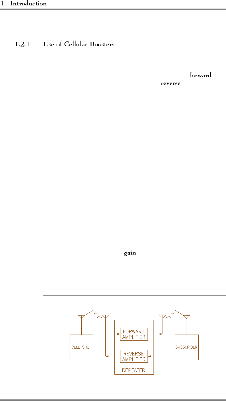
1.2 Introduction to Cellular Boosters
Cellular telephone systems transmit signals in two directions between
cell sites and mobile telephones within the signal coverage area. The
signal path from the cell site to the mobile is called the path,
and the path from mobile to cell site is the path.
Weak signal transmissions may occur within the coverage area
because of indoor applications, terrain obstructions, or distance from
the transmitter. For example—
• Within a large building, signals may be marginal because of
signal attenuation by the building or because subscribers are on
lower floors.
• Steep terrain may shield a portion of the coverage area, causing
unsatisfactory signal levels.
• Coverage of a rural highway may be unsatisfactory because of
its distance from the cell-site transmitter.
One solution in these situations is to add more cell sites. However,
in low-traffic areas, a signal booster may be a much less expensive
way to extend the transmission range. As shown in Figure 1-1, the
booster has an amplifier in each cell-site/mobile path, which receives
the signal, amplifies it, and reradiates it.
The range is extended by the of the receiving and transmitting
antennas and of the booster amplifier itself. Also, the path from the
cell site to the booster is typically line-of-sight and therefore has very
low propagation loss when compared to the typical path to a mobile.
Figure 1-1. Cellular Booster Operation
Page 1-2 AMPS EAC-2000™ Manual: Vol. 3, Technical Information (27-7657-2, 7/95)
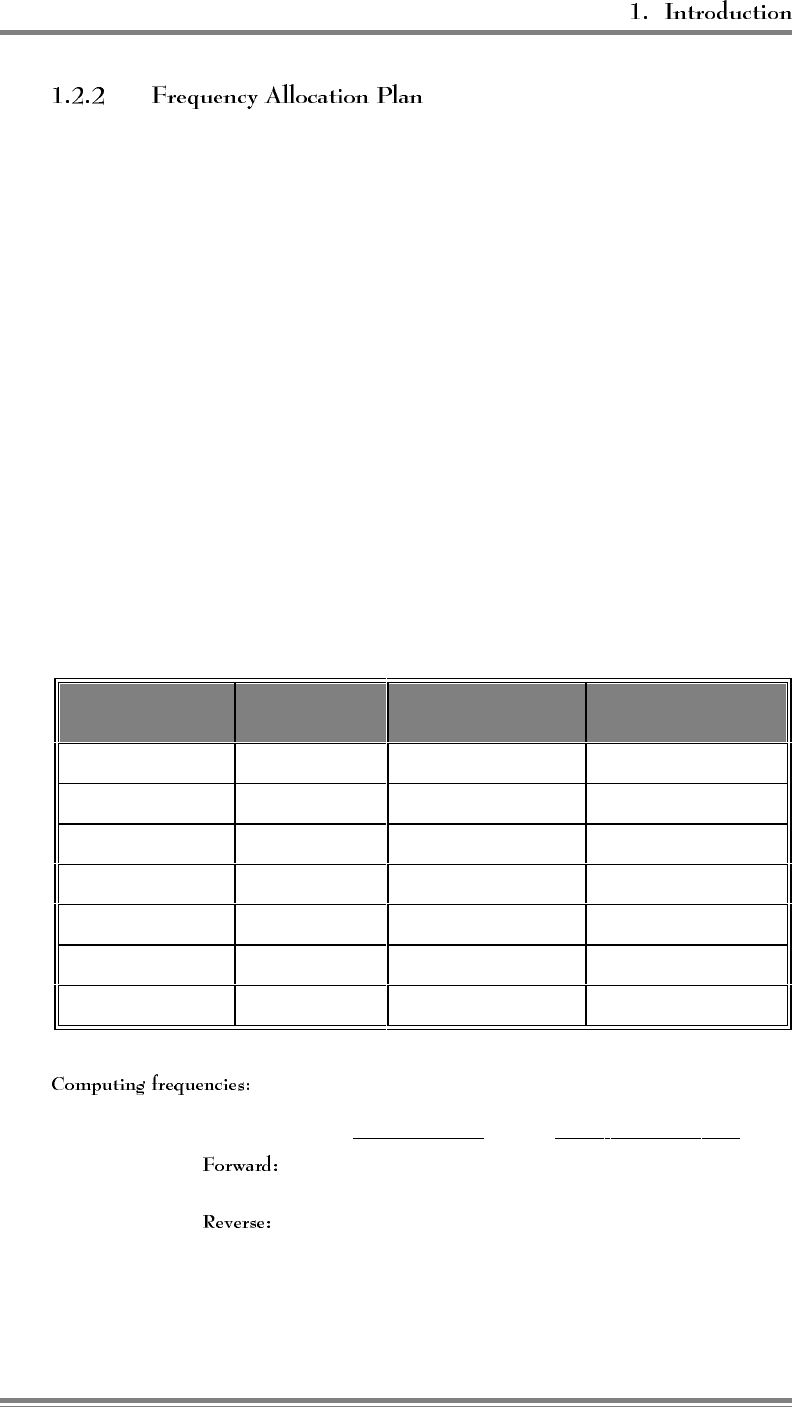
Cellular frequencies for AMPS-compatible systems are allocated as
shown in Figure 1-2. Frequencies 824–849 MHz are used for reverse
path transmissions, and 869–894 MHz are used for forward path
transmissions. These bands of frequencies are divided into 666 full-
duplex channel pairs, each 30 kHz wide. The channels are divided
between two independent systems (A and B), each system receiving
333 channels. Of the 333 channels, 21 are control channels and 312
are voice channels. The control channels for the A and B systems
are next to each other in the center of the band.
The expanded band segments (A', A", and B") provide an additional
2.5 MHz of bandwidth to each licensee. The nonwireline Band A
expansion is provided in two segments: a 1.5 MHz segment (A')
above the B band and a 1 MHz segment ((A") below the A band.
The entire 2.5 MHz wireline band B expansion is above the A'
segment. The formulas for calculating AMOS frequencies from
channel numbers are provided in Figure 1-2.
Figure 1-2. Channel Assignment and Frequency Allocation
Band Designation Channel
Numbers Mobile Transmit
Frequency Land Transmit
Frequency
Band A" 991 1023 824.040 825.000 869.040 870.000
Band A Voice 1 312 825.030 834.360 870.030 879.360
Band A Control 313 333 834.390 834.990 879.390 879.990
Band B Control 334 354 835.020 835.620 880.020 880.620
Band B Voice 355 666 835.650 844.980 880.650 889.980
Band A’ 667 716 845.010 846.480 890.010 891.480
Band B’ 717 799 846.510 848.970 891.510 893.970
For a given channel, the frequencies may be computed as follows:
Channel Number Center Frequency, MHz
1 ≤ N ≤ 7998 0.03N + 870.000 MHz
991 ≤ N ≤ 1023 0.03 (N-1023) + 870 MHz
1 ≤ N ≤ 799 0.03N + 825.000 MHz
991 ≤ N ≤ 1023 0.03 (N-1023) + 825 MHz
AMPS EAC-2000™ Manual: Vol. 3, Technical Information (27-7657-2, 7/95) Page 1-3
6HFWLRQ ($& 'HVFULSWLRQ
2.1 Introduction
This section of the manual describes and illustrates the EAC-2000 design
concept and operation and provides descriptions of the various system boards.
2.2 EAC-2000 Concept
The EAC-2000 booster uses 21 separate narrowband amplifiers. The simplified
diagram in Figure 2-1, shows 4 narrowband amplifiers: 2 (forward and reverse)
for the control channel and 2 (forward and reverse) for the voice channel.
A forward amplifier boosts and translates the frequency of the control
channel transmitted from the donor cell site to the mobiles. A
reverse amplifier boosts and translates the frequency of the control
channel transmitted from the mobiles to the donor cell site.
The narrowband amplifiers are a single channel (30 kHz) wide and
have dual synthesizers that control input and output channels
independently. For example, if the cell site, the EAC-2000, and the
mobiles in the primary coverage area communicate on control
channel 340, the EAC-2000 could be set up to receive control
channel 340, amplify it, and reradiate it on channel 335. The mobiles
in the booster coverage area that are unable to receive channel 340
would lock onto channel 335 and communicate with the cell site
through the EAC-2000. The translated control channel is referred to
as the .
This concept of control channel translation is possible because the
mobiles lock onto the strongest control channel. This is significant
because the mobiles will receive only one signal, even if on the
fringe of the weak coverage area. Therefore, there is no interfering
signal.
AMPS EAC-2000™ Manual: Vol. 3, Technical Information (27-7657-2, 7/95) Page 2-1
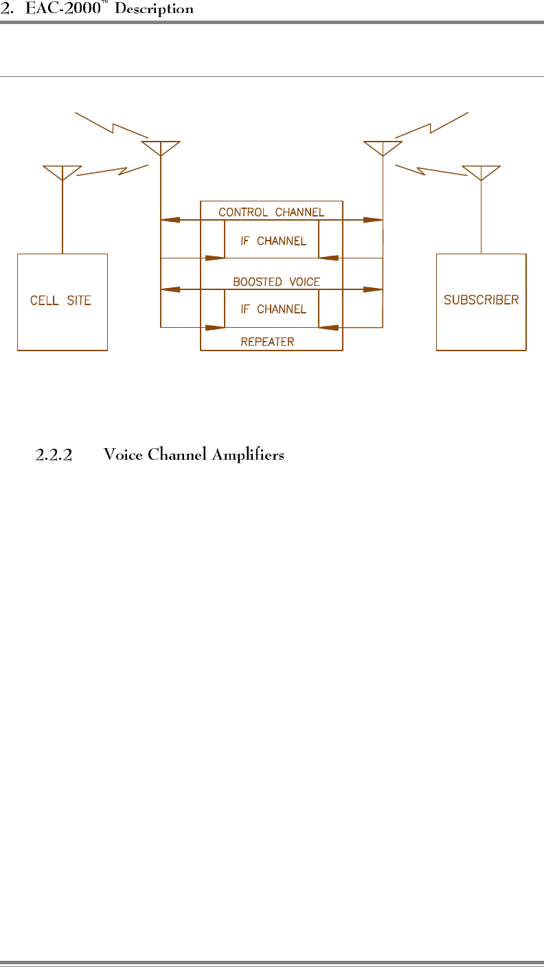
Figure 2-1. EAC-2000 Concept
The EAC-2000 also contains narrowband forward and reverse
amplifiers for boosting voice channels. These amplifiers, which are
keyed as needed when voice channel activity is detected in the
boosted coverage area, translate the frequency of the boosted signal.
When a mobile is detected in the coverage area, a voice channel
booster is set up, and a hand-off message is sent to the mobile,
causing it to switch to the boosted voice channel.
Page 2-2 AMPS EAC-2000™ Manual: Vol. 3, Technical Information (27-7657-2, 7/95)
2.3 EAC-2000 Operation
Several aspects of EAC-2000 operation are described in this section:
• Antennas
• Forward path operation
• Reverse path operation
• Hand-off messages
Refer to the block diagram at the end of Section 3 in conjunction with the
written descriptions.
The EAC-2000 uses four antennas:
• (lower right corner of block diagram): Primary
antenna facing donor cell site(s), used for:
- Reception of control and voice channel signals from donor
cell site(s).
- Transmission of control and voice signals back to cell
site(s).
• (lower left corner of block diagram): Primary
antenna facing mobiles in the booster coverage area, used for:
- Transmission of boosted control channel and boosted voice
channels to mobiles.
- Diversity reception from mobiles.
• (center bottom of block diagram): Second antenna
facing mobiles in the booster coverage area, used for:
- Sending hand-off messages to mobiles.
- Diversity reception from mobiles.
- Sending control data to Multi-Donor Units, when installed
• (not shown): Antenna for the installed
cellular mobile, facing the donor cell site.
AMPS EAC-2000™ Manual: Vol. 3, Technical Information (27-7657-2, 7/95) Page 2-3

RF signals transmitted by the cell site (on both control and voice
channels) are received at the D1 antenna and passed through the
duplexer to the forward preamplifier. The forward preamp amplifies
the signal and provides RF output to the narrowband forward receiver
of the RF boards.
The signals coming out of the forward transmitter of each RF board
are fed to a 45-watt power amplifier (PA). The PA outputs are
combined in a transmit combiner. Note that the output channels for
the forward direction are fixed by this combiner. The output of the
combiner is fed to another duplexer, which is coupled to the M1
antenna facing the desired coverage area.
The reverse path through the system, starting with signals transmitted
by the mobiles and received at the M1 antenna, is similar to the
forward path. The reverse preamp has an additional RF input from
the M2 antenna. Each RF board attached to the preamp can
individually select the M1 or the M2 input as part of a diversity
algorithm.
An important difference between the two paths is in the output power
capability. The forward path employs separate 45-watt PAs, which
are combined through a conventional transmit combiner. PAs 1–5
and 7-11 must operate on the fixed channel to which their associated
combiner cavity is tuned. By contrast, the reverse path signals are
amplified on each board and passively combined in a reverse
combiner assembly, allowing the reverse transmitted signals to
operate on any channel.
The reverse signals operate at a much lower power level, however,
because the link between the cell site and the EAC-2000 is fixed (and
probably line-of-sight), whereas the link between the EAC-2000 and
mobiles is not as reliable. A balanced system (that is, a system with
similar forward and reverse gains) requires higher power PAs in the
forward direction. In addition, since the signal from the mobiles may
be weak, diversity is employed by the reverse path receivers on each
RF board.
Page 2-4 AMPS EAC-2000™ Manual: Vol. 3, Technical Information (27-7657-2, 7/95)

The sixth RF board is used for scanning and sending handoff
messages.
• The reverse path portion is used to scan the donor voice
channels for mobiles that may enter the booster coverage area.
• The forward path portion of this board is connected
to a 45-watt PA 6, which is connected to the M2 antenna
duplexer. Since this path is not combined, the hand-off/locating
board can transmit with high power level on any channel. This
capability is used to send hand-off messages to mobiles, causing
the mobile to tune to one of the fixed forward channels
associated with boards 1–5 and 7–11.
• Board 6 is also used as a backup control channel booster.
AMPS EAC-2000™ Manual: Vol. 3, Technical Information (27-7657-2, 7/95) Page 2-5
2.4 System Board Functions
The EAC-2000 system includes the following boards:
• RF boards
• Backplane board
• Controller board
• Forward pre amp
• Reverse pre amp
• Reverse combiner
• 45-watt power amplifier
• DC-DC converter shelf
• PA interface
• Mobile shelf
Figure 2-3 shows a more detailed block diagram of one RF path on
the RF boards. Forward and reverse paths differ only in tuning.
In the forward direction, one of the signal paths from the preamp
board is fed to a mixer/synthesizer on the narrowband forward path.
The signal is translated down to the 45 MHz intermediate frequency
(IF), where it is further filtered and amplified. The IF filter is one
channel (30 kHz) wide, allowing only the selected channel to be
amplified. After passing through the IF filter, the signal is translated
back up by another mixer/synthesizer. Since the two synthesizers are
not tied together, the receive and transmit channels can be set
independently.
A on the narrowband boards controls all outputs
(input channel, output channel, gain, and antenna select output),
monitors inputs (RSSI and synthesizer lock), runs the diversity
algorithm and detects signaling tone.
Page 2-6 AMPS EAC-2000™ Manual: Vol. 3, Technical Information (27-7657-2, 7/95)
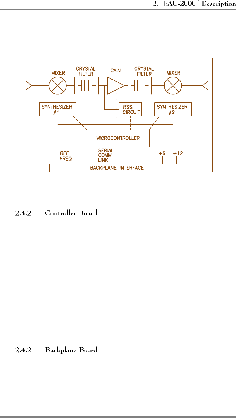
Figure 2-3. RF Board Block Diagram
The controller board contains—
• Controller microprocessor
• 128 kilobytes of EPROM
• 32 kilobytes of nonvolatile RAM
• Watchdog timer
• RS-232 interface
• Reference oscillator
Because all system parameters (e.g., channel numbers, gains) are
stored in non-volatile RAM, the system will resume operation after
a power outage in the same state as before the outage. The RS-232
interface connects a serial port to a local terminal. Monitor software
allows system parameter entry and system monitoring.
The RF boards and the controller board plug into the backplane
board. Connectors on the backplane connect dc and RF with the rest
of the system.
AMPS EAC-2000™ Manual: Vol. 3, Technical Information (27-7657-2, 7/95) Page 2-7
The forward preamp board receives input from the D1 antenna via
the D1 duplexer. The board amplifies then splits the signal,
providing output to each of the 11 RF boards. The board has net loss
of 7 dB typical. The amplifier section is designed for high intercept
point.
The reverse preamp board receives input from the M1 and M2
antennas via duplexers. The board amplifies and splits both signals.
Each RF board has a control line connecting to the reverse preamp
that controls which signal is used (M1 or M2). The reverse preamp
is designed for good sensitivity and provides about 11 dB gain
typical.
The reverse combiner is entirely passive and broadband. Signals
from the reverse transmitter of the RF boards are fed in at about +33
dBm. The signals are passively combined to a single output with net
loss about 12 dB.
The 45-watt PA is a standard base station design with added front
end gain. The unit has a pot on the front which allows the power
output to be manually adjusted downward 7 to 10 dB. The PA also
has three digital inputs (only two are used) which allow digital setting
of the power output to one of four steps:
• Step 0/ = full power
• Step 1 = 4 dB down
• Step 2 = 8 dB down
• Step 3 = 12 dB down
The PA has forward power sense and temperature sense outputs.
Page 2-8 AMPS EAC-2000™ Manual: Vol. 3, Technical Information (27-7657-2, 7/95)
Each PA cage may contain up to six 45-watt PAs and will contain
one PA interface board. The purpose of this board is to condense the
numerous control and sense leads required for the PAs to a relatively
low number of wires, which are connected to the controller board via
the cabinet harnessing. This board can be viewed as an "I/O
Expander" which is fully controlled by the controller board.
The PA interface board has power control outputs to each PA, a
temperature sense, and forward power sense coming from each PA.
The PA interface board also contains some undedicated outputs and
inputs which are routed to the external alarms/controls connector at
the back of the PA cage.
The mobile shelf contains—
• Interface to cellular mobile
• External dialer modem
This setup allows remote control of the system via the mobile. The
system can be set up to initiate a call over this link when an alarm
condition occurs.
The power supply system consists of—
• Dual switching 28 volt supplies (supply power for the PAs and
for dc-dc converters)
• 28-to-12 volt dc-dc converter (supplies power for the RF
portions of the boards)
• 28-to-6 volt dc-dc converter (supplies power for the logic
portions of the system)
The dc-dc converters are contained in the regulator module.
AMPS EAC-2000™ Manual: Vol. 3, Technical Information (27-7657-2, 7/95) Page 2-9
2.5 How Calls Are Processed
The EAC-2000 is capable of boosting up to 10 channels at once, while the donor
cell may employ 15 or more channels. The EAC-2000’s call processing
algorithms dynamically allocate the RF boards to service only mobiles in the
booster coverage area.
The EAC-2000 identifies mobiles in the booster coverage area by two methods:
one for identifying mobiles that place or answer calls from within the booster
coverage area and another for identifying mobiles that enter the area with a call
in progress.
To identify calls placed or answered from within the booster coverage
area, the EAC-2000 monitors the data streams on the boosted control
channel, both forward and reverse. When a mobile that is not
engaged on a call drives into the booster coverage area, it normally
rescans and locks onto the strongest control channel (the boosted
control channel). If, once inside the booster coverage area, that
mobile places or answers a call, the following sequence occurs:
1. The mobile accesses the reverse boosted control channel. The
EAC-2000 receives the access, then accesses the reverse donor
control channel.
• The EAC-2000 waits for the corresponding voice channel
designation message on the forward channel.
• The EAC-2000 modifies the voice channel designation
message by substituting one of its boosted voice channels
for the donor voice channel, thus sending the mobile to
one of the boosted voice channels.
2. A boost path is set up between the mobile and the primary
donor cell site, with the mobile operating on the boosted voice
channel, the donor operating on the donor voice channel, and
the EAC-2000 translating and boosting between the two.
The is defined as the cell site whose control
channel the EAC-2000 is boosting. All mobiles that originate or
answer calls through the EAC-2000's boosted control channel will be
.
Page 2-10 AMPS EAC-2000™ Manual: Vol. 3, Technical Information (27-7657-2, 7/95)
To identify mobiles that may
drive into the boosted coverage area with a call in progress (i.e.,
already on a voice channel), the EAC-2000 scans the donor voice
channel in the mobile transmit band and maintains an RSSI average
for each channel. If the average RSSI exceeds a preset
, and the SAT on the channel is correct, the mobile on that
channel is considered a candidate.
Once a candidate is identified, the EAC-2000 forces
the mobile to one of the boosted voice channels. To do this, the
transmit portion of the hand-off/locating board (board 6) and PA 6 is
used to send a hand-off message to the mobile. A boost path is set
up for that channel in the same fashion as if the candidate had been
identified by decoding the data streams.
To provide for situations in which in-
progress calls may be linked to various neighboring cell sites, the
monitoring system allows for entry of three separate
, one for each possible SAT frequency.
• If the booster is adjacent to a single cell site, the control
channel of that cell site is the . The
voice channels used in that cell site may be entered into the
donor voice channel list with the SAT of that cell site to handle
mobiles that drive between the donor and booster with a call up.
• If the booster is adjacent to several cell sites, the voice channels
of all the neighboring cells are entered into the scan list with the
SAT of the neighboring cells. The control channel of one of
the cell sites is chosen as the donor control channel, and this
cell is then referred to as the .
As noted earlier, calls placed or answered from
within the booster coverage area (and identified by decoding data
streams) are boosted back to the primary donor cell. By contrast, in-
progress calls identified by the channel scanning process are
. That is,
if a mobile drives in with a call-up to a neighboring cell, the EAC-
2000 will boost the call back to that neighbor. This means that the
RF path between the EAC-2000 and any possible donor must support
booster operation.
Note that if multiple donors are used, the D1 antenna system at the
EAC-2000 must be specially designed for this operation.
Specifically, signal strength at the D1 antenna must be close to
identical (within ±2 dB) from all possible donor cell sites.
AMPS EAC-2000™ Manual: Vol. 3, Technical Information (27-7657-2, 7/95) Page 2-11
Once a booster pair has been set up, the EAC-2000 monitors for one
of the following conditions to determine when to hand back the
mobile (that is, take down the booster on that channel):
•SAT fade
• Mobile release (1.8 seconds of signaling tone on the reverse
voice channel)
• Weak mobile RSSI (RSSI received from the boosted mobile
goes below a preset )
• Weak donor RSSI
Weak mobile RSSI identifies the mobile as a hand-back candidate.
Once a hand-back candidate is identified, the EAC-2000 sends the
mobile a hand-off message directing it back to the original donor
voice channel. This allows the mobile to be covered as it drives out
of the booster coverage area back into the donor cell site coverage
area.
Sometimes a mobile
leaving the booster area will drive out of cellular coverage. In this
situation, handing the mobile back to the original donor cell would
result in a weaker or nonexistent signal.
To handle this situation, the EAC-2000 uses the .
Shortly after sending the hand-off message, the EAC-2000 tries to
hand the mobile back to the booster by sending it a second hand-off
message (called a ) directing the mobile to come
back to the boosted voice channel. When the grab-back message is
sent, however, the mobile (because of the first hand-off message) is
on the donor voice channel and possibly is receiving signal from the
donor cell site.
• If the signal from the donor is stronger than the signal from the
EAC-2000, the mobile will ignore the grab-back message and
remain on the donor voice channel. The EAC-2000 will then
free up the equipment it was using to boost the call, since the
mobile is now being handled directly by the donor.
• If the EAC-2000 signal is stronger during the grab-back
message (as would be the case if the mobile were driving away
from the EAC-2000 but not toward the donor cell that was
handling the call), the mobile will come back to the booster
voice channel, and the EAC-2000 will continue to boost the
mobile.
Page 2-12 AMPS EAC-2000™ Manual: Vol. 3, Technical Information (27-7657-2, 7/95)

(Continued)
The entire hand-back/grab-back process takes only about 500
milliseconds. Once a mobile comes back to the booster after a hand-
back/grab-back, that mobile will not be considered a hand-back
candidate again for several seconds (a programmable parameter),
regardless of its signal level. The EAC-2000 will periodically send
hand-back/grab-backs but continue to handle the mobile until the
signal level is unusable.
If a mobile being boosted back to one
donor cell drives toward another donor cell, a dilemma occurs. The
serving cellular system thinks the mobile is on one voice channel,
while the booster actually has it translated to another channel.
The signal level from the booster to the donor is set such that it is
below the donor’s hand-off candidate threshold. The donor will thus
always identify the boosted mobile as a candidate for hand-off, and
the cellular system will try to find the mobile in the cell sites adjacent
to the donor. Since the mobile is actually on the booster’s translated
voice channel, it will not be seen in any cell site, so a system hand-
off will not occur.
A solution is to provide a means for the adjacent cell sites to see the
mobile on the voice channel that the cellular system thinks it is on.
Once this is accomplished, the cellular system can determine which
adjacent cell the mobile is driving into, assign a voice channel in that
cell, and then send a hand-off message for the mobile to go to that
channel.
This can be achieved by placing a reverse-translating
(Allen Telecom Systems) at each of the cell sites adjacent to
the booster. The unit is connected to the cell-site receive antennas to
scan for boosted mobiles and then translate those mobiles back to the
donor’s voice channel for presentation to the cell-site locating
receiver.
The Multi-Donor Units must know the relationships in effect between
boosted and donor channels for calls being handled by the EAC-2000
booster(s). This is accomplished by data signaling between the EAC-
2000 and any adjacent Multi-Donor Units on a booster link channel.
AMPS EAC-2000™ Manual: Vol. 3, Technical Information (27-7657-2, 7/95) Page 2-13
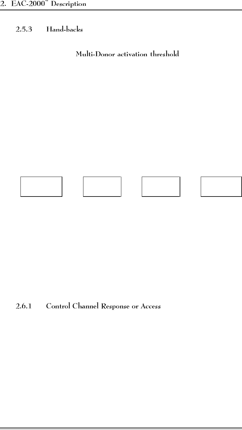
(Continued)
The EAC-2000 looks for the boosted mobile signal level to fall below
a settable . If this happens, the
booster encodes and transmits the channel relationships to any Multi-
Donor Units that may be listening. However, this does not mean the
mobile will necessarily be handed off. Transmission of this
information merely allows the Multi-Donor Unit to know (if it is able
to see the mobile signal at sufficient level) to which channel it should
"untranslate" the mobile.
2.6 Multi-Hop Operation
Multi-hop operation (illustrated below) involves setting up two or more EAC-
2000 units (or EAC-2000 units and EAC-IV units) to operate together in a
line—for example, along a major corridor leading into a metropolitan area.
Donor
Cell ⇔Booster
#1 ⇔Booster
#2 ⇔Booster
#3
The boosters are set up so that there is a two-way RF path between the donor
and booster #1 and between each pair of adjacent boosters. This arrangement
can be used to handle situations in which a mobile—
• Places or answers a call while in the coverage area of any of the boosters.
• Drives across the coverage boundary:
- Donor-to-booster
- Booster-to-booster (away from donor)
- Booster-to-booster (toward donor)
- Booster-to-donor
When a mobile places or answers a call, the first exchange of
information occurs on the reverse control channel (from mobile to
donor). If the call is a mobile-answered call, the exchange is a page
response. If it is a mobile-originated call, the mobile does an access.
There is little difference in the way EAC-2000 boosters handle these
two. Since the mobiles self-locate, the control channel chosen for the
access determines in which booster's coverage area (if any) the
mobile is located.
Page 2-14 AMPS EAC-2000™ Manual: Vol. 3, Technical Information (27-7657-2, 7/95)
All boosters between the terminating booster and the donor cell
repeat the access or page response and decode it. From the decoding
they extract the mobile identification number (MIN). Next, the
cellular system assigns a voice channel to that particular mobile by
sending, over the forward control channel, an initial voice channel
designation (IVCD) message consisting of the mobile’s MIN and a
voice channel that will be used by the donor for the call.
The multi-hop boosters are all monitoring the forward control channel
data stream. The boosters that decoded the access or page response
on the reverse control channel also decode the corresponding IVCD
message on the forward channel.
Booster #1 substitutes its chosen boosted channel for the donor voice
channel in the IVCD message and sets up a boost path between the
donor-assigned voice channel and the boosted voice channel of
booster #1. Likewise, booster #2 changes the channel number in the
IVCD message and sets up a boost path between the boosted voice
channels of boosters #1 and #2.
All of the boosters between the terminating EAC-2000, where the call
is placed, and the donor cell will in this fashion identify that
particular mobile as a candidate for repeating and will have decoded
the donor channel assigned.
The mobile will decode the IVCD message from the terminating
EAC-2000 and go to the boosted voice channel assigned by it. All
EAC-2000s between the donor and the terminating one will
simultaneously set up boost paths between the previous EAC-2000
(or donor) and the next EAC-2000. Thus the path from mobile to
donor is complete.
AMPS EAC-2000™ Manual: Vol. 3, Technical Information (27-7657-2, 7/95) Page 2-15

2.7 Local/Remote Link
The operating parameters of the EAC-2000 can be programmed and monitored
locally, through a serial link attached to a standard RS-232, ASCII terminal.
The same control can be exercised remotely via a telephone line, modem, and
the same kind of terminal.
The local link is established by connecting a conventional ASCII, RS-
232 terminal to the 25-way D-sub connector on the EAC-2000
controller board. The terminal should be set for 9600 baud, even
parity, 7 data bits, 1 stop bit, full duplex (no local echo), all capitals,
disable auto XON/XOFF and soft scroll, and "carriage return only."
The EAC-2000 comes equipped with an integral modem attached to
an installed cellular mobile radio.
This equipment makes it possible to dial up and communicate with
the EAC-2000 using a remote terminal and compatible modem. The
EAC-2000 can also be set up to automatically dial a predetermined
telephone number if a major fault occurs.
Once the remote link is established, the interface with the system is
exactly like that on the local link, but at a different baud rate. If both
links are up, characters typed on either terminal are echoed to both,
along with the resulting EAC-2000 output. This makes it possible for
an experienced operator to exercise the system remotely while
someone watches locally, or for the two to exercise the system
together.
2.8 Programmable Parameters
Virtually all of the operating parameters of the EAC-2000 are under software
control. For descriptions of the programmable parameters and the available
options for each, refer to Volume 2, Section 2.
2.9 Alarms
The EAC-2000 constantly monitors and logs a variety of alarm conditions. For
descriptions of these alarm conditions, see Volume 2, Section 3.8.
Page 2-16 AMPS EAC-2000™ Manual: Vol. 3, Technical Information (27-7657-2, 7/95)

6HFWLRQ 6SHFLILFDWLRQVDQG'UDZLQJV
3.1 Specifications
Specifications for power, environment, mechanical, RF, interface, and general
purpose alarm/control connections are given in Figure 3-1.
Figure 3-1. Specifications
Power
Recommended ac service:
AC power requirements
(for 10 channel operation):
28 Vdc power supply
without battery plant
28 Vdc power supply
with battery plant
System dc power requirements
(supplied by 28 V power supply):
200–240 Vac, single-phase
50/60 Hz
20 amp min.
2900 watts max.
4000 watts max.
19–30 Vdc
100 amps max.
Environment
Operating temperature:
Relative humidity:
Storage temperature:
-30o to +60oC
95% max @ +50oC
-40o to +75oC
Mechanical
Outdoor cabinet dimensions (HxWxD):
Weight:
68 x 24 x 40 in
(169.7 x 62.2 x 101.6 cm)
Approximately 690 lbs (363 kg)
AMPS EAC-2000™ Manual: Vol. 3, Technical Information (27-7657-2, 7/95) Page 3-1

Figure 3-1. Specifications (Continued)
RF
Gain:
Overall reverse path noise figure:
Channel filter bandwidth
Maximum input signal level:
Frequency tracking accuracy
(for channel boost mode):
RSSI range:
Reverse:
Forward:
RF power amplifiers:
PAs 1–10 (forward direction):
PA 6 (hand-off transmitter):
Reverse direction:
> 120 dB
< 12 dB
> 26 kHz @ -6 dB
> 75 kHz @ -60 dB
-40 dBm
±1.5 Hz max per MHz of translation
-120 to -20 dBm
-100 to -20 dBm
45-watt
45-watt
10 x 2-watt (combined linearly)
Programmable frequency control:
Spacing:
Range:
Channels:
Output frequency accuracy
(for data transmission mode):
30 kHz
824–849 MHz
869–894 MHz
1–799, 991–1023
±1.5 ppm ±0.25 ppm ±0.25 ppm
max. max. max.
Maximum usable power output:
(Measured at antenna connector,
after internal combiner and duplexer
losses)
M1 antenna port (forward
direction):
M2 antenna port (hand-off):
D1 antenna port (reverse
direction):
5-Channel 10-Channel
20 watts/channel 15 watts/channel
100 watts total 150 watts total
20 watts max.
100 milliwatts per channel
1.0 watt total
Page 3-2 AMPS EAC-2000™ Manual: Vol. 3, Technical Information (27-7657-2, 7/95)

Figure 3-1. Specifications (Continued)
Interface
Antenna connectors:
Local diagnostic interface:
Remote diagnostic interface:
Type N
RS232, ASCII
9600 baud, even parity, 7 data bits, 1 stop
bit, full duplex
Microcomm TravelPorte™ (high-speed, error
correcting, data compression modem)
General Purpose Alarm/Control
Connections
Digital Inputs (pins 6, 7, 8, 9):
Load:
Low:
High:
Open Collector Outputs
(pins 2, 3, 4, 5):
Analog inputs
(pins 10, 11, 12, 13):
Load:
Range:
+5 Vdc source (pin 1):
> 100 kΩ
< 2 Vdc
> 4 Vdc max. +28 Vdc
Max. +15 Vdc, 20 mA
Impedance 733 Ω
1 MΩ
0–5 Vdc, 20 mV resolution
+5 Vdc ±5%, 100 mA max.
AMPS EAC-2000™ Manual: Vol. 3, Technical Information (27-7657-2, 7/95) Page 3-3
3.2 Equipment Characteristics
EAC-2000 accessories, module interchangeability, compliance, and reliability are
described in this section, along with skills required for servicing the equipment.
The following items are supplied with the EAC-2000:
• EAC-2000 Technical Manual (Volumes 1, 2, and 3), power
supply manual, mobile manual, modem manual
Inside the EAC-2000, the following modules are interchangeable:
• RF boards (positions 1–11)
• 45-watt PAs
The EAC-2000 complies with the applicable agency rules regarding
cellular base stations for AMPS systems.
• The unit is designed to work in
systems that comply with—
- EIA/TIA 553A Cellular System Mobile Station–Land
Station Compatibility Specification
- EIA/TIA IS-20A, Recommended Minimum Standards for
800 MHz Cellular Land Stations
- EIA/TIA IS-19B, Recommended Minimum Standards for
800 MHz Cellular Subscriber Units
- RSS-118, Radio Standards Specification, Canada
• The EIA/TIA IS54A and IS54B
Cellular system Dual-Mode Mobile Station - Base Station
Compatibility Standard specifies both analog and digital modes
of operation. The EAC-2000 is not capable of boosting digital
calls. However, the EAC-2000 can operate with dual mode
systems and dual mode mobiles. The EAC-2000 control
channel always transmits with the "PCI" bit clear. Dual mode
radios operating on the boosted control channel therefore access
using the EIA 553 (i.e., analog) protocol. The donor cell,
whether dual mode or not, will assign an analog channel, and
the EAC-2000 will boost the call.
Page 3-4 AMPS EAC-2000™ Manual: Vol. 3, Technical Information (27-7657-2, 7/95)
(Continued)
• The Motorola NAMPS Air
Interface Specification specifies both a 30 kHz wide channel
operation and a 10 kHz wide channel operation. The EAC-2000
is not capable of boosting calls assigned to narrow channels.
However, the EAC-2000 can operate with both NAMPS radios
and NAMPS systems. The EAC-2000 control channel always
transmits with the "EP" bit clear. NAMPS radios operating on
the boosted control channel therefore access using the EIA 553
protocol. The donor cell, whether NAMPS capable or not, will
assign a wide channel, and the EAC-2000 will boost the call.
• This modem is compatible with the
following modem standards:
Bell 103
Bell 212A
CCITT V.21
CCITT V.22
CCITT V.22 BIS
CCITT V.32
CCITT V.42
CCITT V.42 BIS
MNP Class 5
MNP Class 10
• The cellular radio used for remote mode
operation is a standard unit and complies with applicable
standards.
Careful consideration has been given to the reliability of the unit
during design.
• In most cases, is based on derating component
specifications to 50% or less of guaranteed limits.
•The has transient protection to guard against
lightning and power line surges.
•The circuitry has a low voltage reset and
watchdog timer to provide firmware program reliability.
The microprocessor components and circuitry require service by
personnel skilled in repairing firmware-driven logic assemblies. The
RF circuitry contains surface-mounted components that require
special care when being repaired.
AMPS EAC-2000™ Manual: Vol. 3, Technical Information (27-7657-2, 7/95) Page 3-5

3.3 EAC-2000 Illustrations
Figures 3-2 and 3-3 illustrate front and back views of the AMPS EAC-2000 with
the doors removed.
3.4 EAC-2000 Diagrams
Figure 3-4 shows the regulator module wiring diagram, and Figure 3-5 shows
the power supply shelf wiring diagram. In addition, the following foldout
diagrams are included in this section:
• Block Diagram
• Main Harness Wiring Diagrams
• Card Cage Wiring Diagram
• Backplane Wiring Diagram
• PA Cage Wiring Diagram
• Mobile Shelf Wiring Diagram
Page 3-6 AMPS EAC-2000™ Manual: Vol. 3, Technical Information (27-7657-2, 7/95)
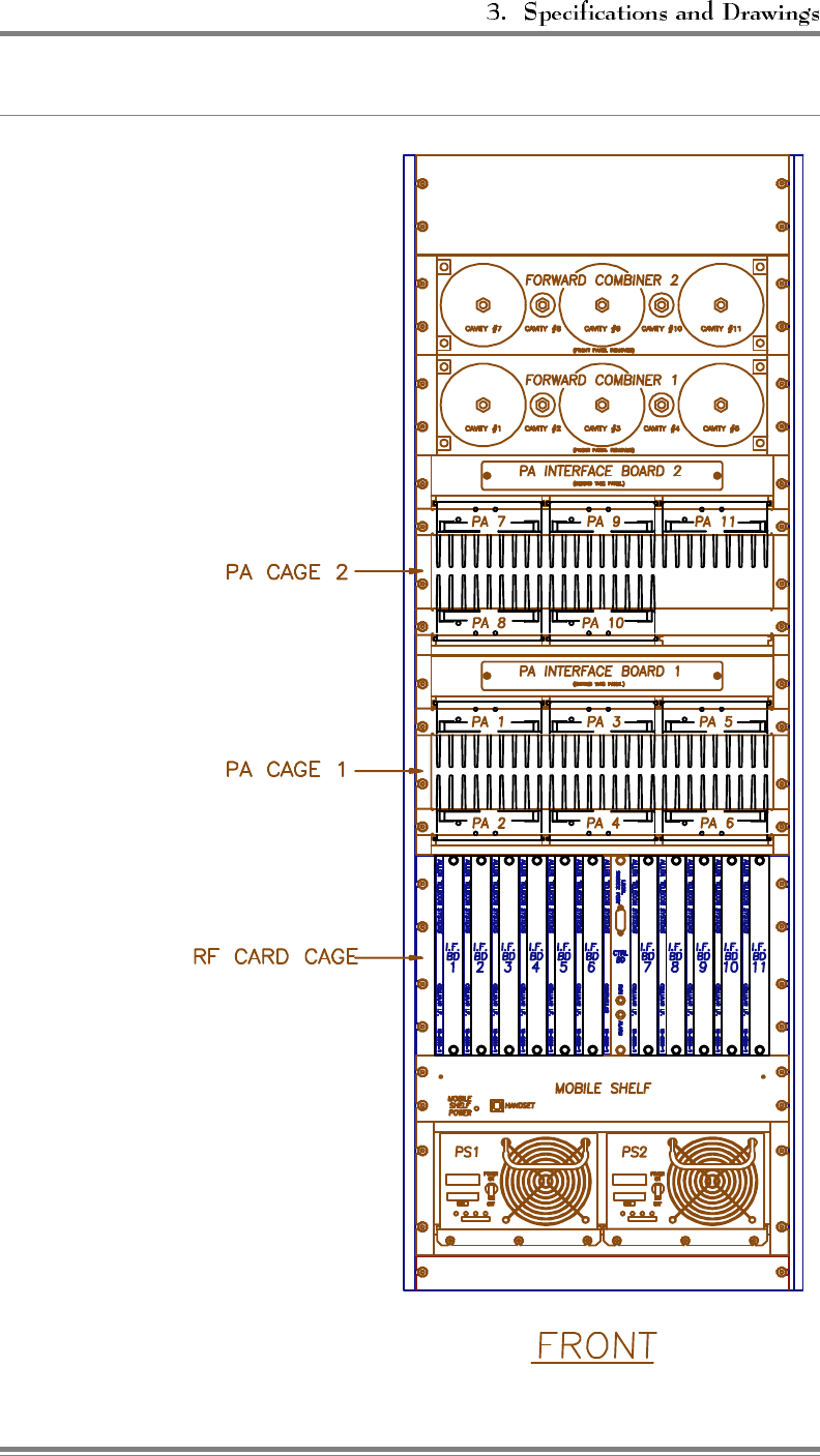
Figure 3-2. AMPS EAC-2000, Front View (Door Removed)
AMPS EAC-2000™ Manual: Vol. 3, Technical Information (27-7657-2, 7/95) Page 3-7
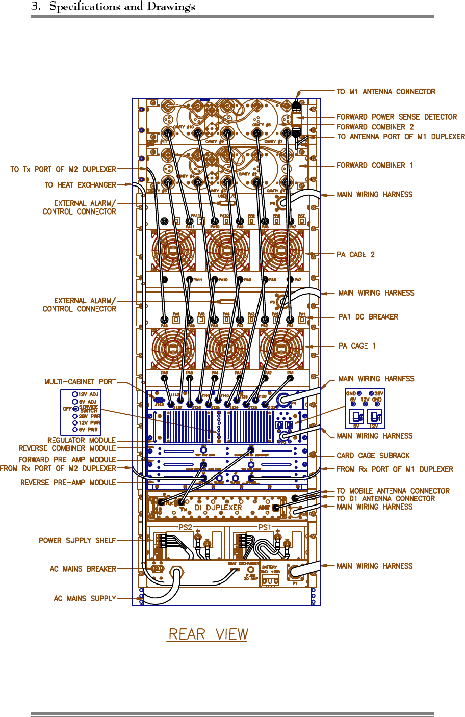
Figure 3-3. AMPS EAC-2000, Back View (Door Removed)
Page 3-8 AMPS EAC-2000™ Manual: Vol. 3, Technical Information (27-7657-2, 7/95)
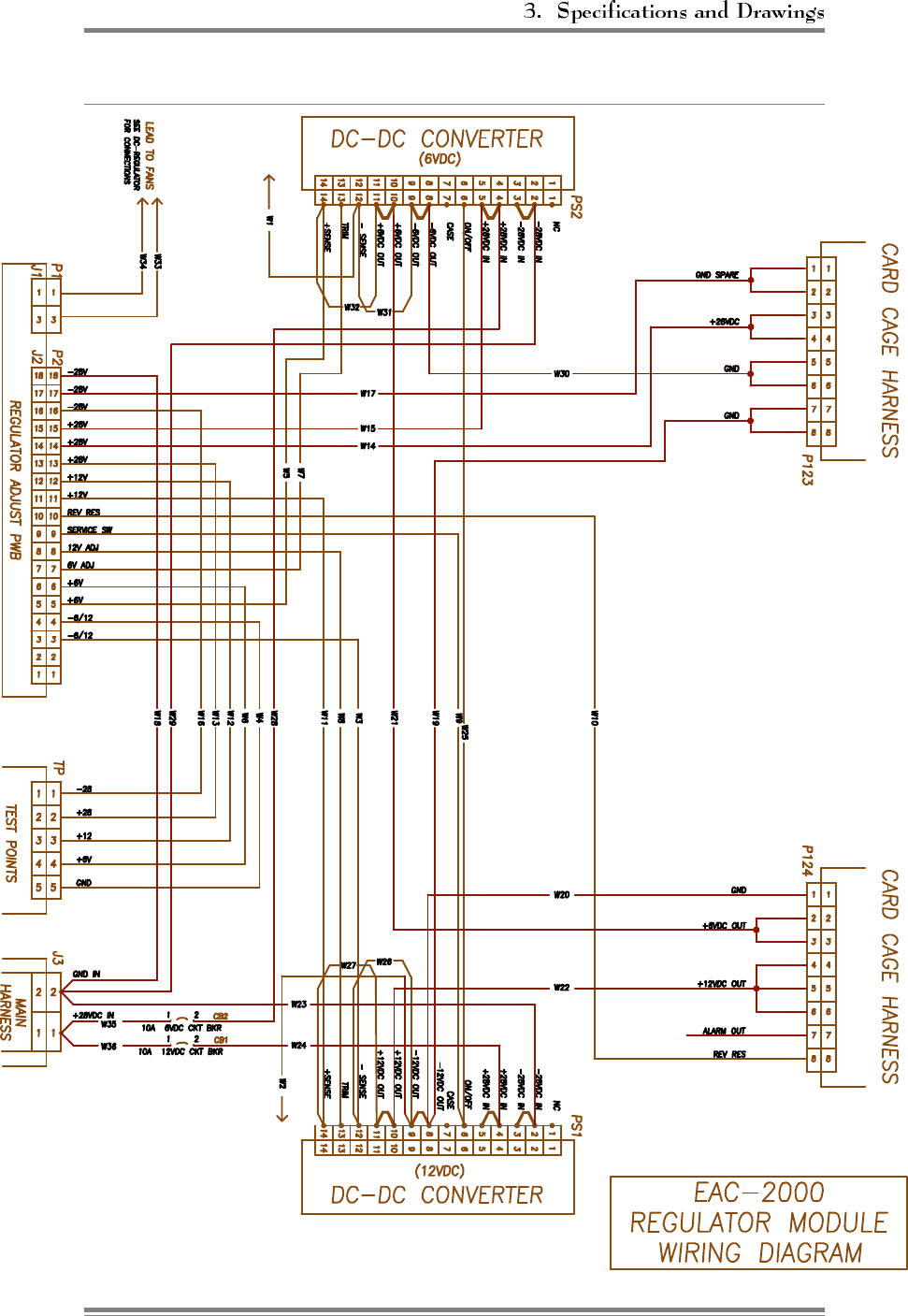
Figure 3-4. Regulator Module Wiring Diagram
AMPS EAC-2000™ Manual: Vol. 3, Technical Information (27-7657-2, 7/95) Page 3-9
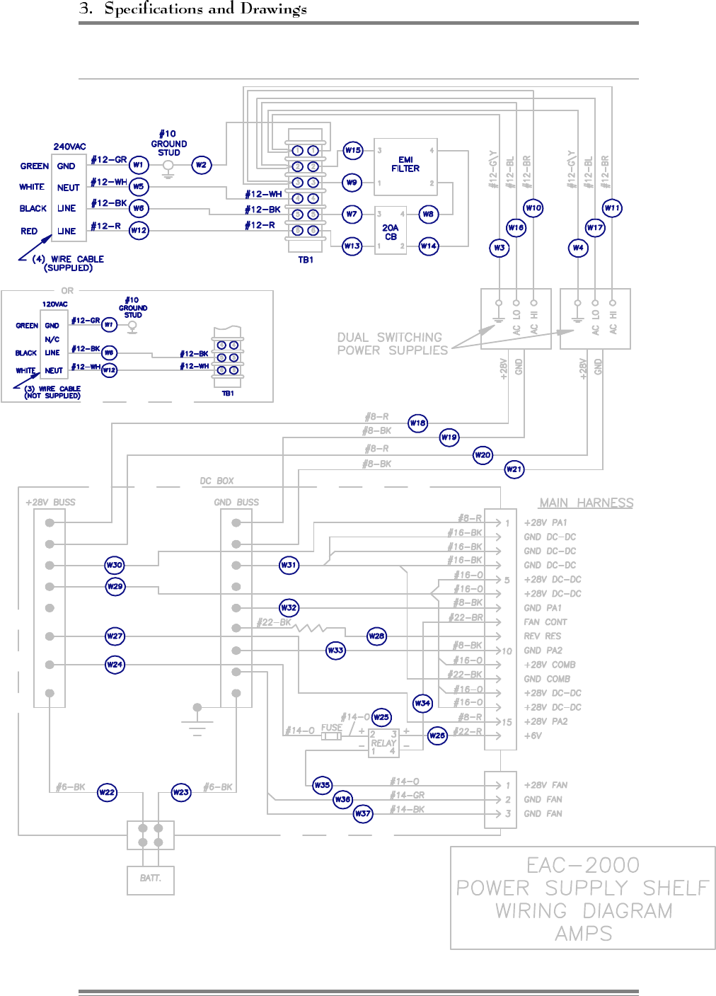
Figure 3-5. Power Supply Shelf Wiring Diagram
Page 3-10 AMPS EAC-2000™ Manual: Vol. 3, Technical Information (27-7657-2, 7/95)

$SSHQGLFHV
27-7658-3
Issue 12/95
© Copyright 1995 Allen Telecom Systems
All Rights Reserved

Field Support
If you need technical assistance with the EAC-2000™, contact
at one of the following telephone numbers:
Extend-A-Cell : (800) 800-EAC4 (3224)
or (216) 349-8413
Systems Engineering Department: (216) 349-8413

$SSHQGL[$
7URXEOHVKRRWLQJ*XLGH
Contents
A.1 Getting Help .........................................A-3
A.2 Basic Troubleshooting Tips ............................... A-3
A.2.1 Illegible Display ...............................A-3
A.2.2 No Display................................... A-3
A.2.3 No Power on Channel ........................... A-4
A.3 Donor-Dropped Calls ...................................A-6
A.3.1 Weak Signals from Donor ........................A-6
A.3.2 Cellular System Hand-offs ........................A-7
A.3.3 Donor RSSI < Threshold Counts (Nominal Number) ...... A-8
A.3.4 Donor RSSI < Threshold Counts (Large Number) ........ A-9
A.4 Calls Not Processed ................................... A-10
A.5 Poor Talk-Back Range (Mobile-to-Booster) ................... A-11
A.6 Dropped Calls Near Edge of Booster Coverage Area ............ A-13
A.7 Excessive Hand-backs/Hand-ins on Voice Channel .............. A-15
A.8 No Hand-in ......................................... A-16
A.9 No Hand-back ....................................... A-16
A.10 Dropped Calls Along Multi-Hop Path ....................... A-17
A.11 Unsuccessful Setups ................................... A-18
A.12 Dropped Calls Due to SAT Fades ......................... A-19
A.13 Cross-Talk.......................................... A-20
A.14 Erratic Operation of Remote Modem ....................... A-22
AMPS EAC-2000™ Manual: Appendices (27-7658-3, 12/95) Page A-1

Contents (Continued)
A.15 Alarms ............................................ A-23
A.15.1 SYN LOC Alarms ............................ A-23
A.15.2 I2C and EEPROM Alarms ....................... A-23
A.15.3 RF COM Alarms ............................. A-23
A.15.4 Personality Alarms ............................ A-23
A.16 Noise . . ........................................... A-26
A.16.1 Burst Noise at the Mobile ....................... A-26
A.16.2 Transmitter Output Noise, Forward Direction .......... A-28
A.17 Trouble Locking Onto Control Channel...................... A-29
Page A-2 AMPS EAC-2000™ Manual: Appendices (27-7658-3, 12/95)
A.1 Getting Help
The procedures in this appendix may be used in case of trouble. For help
with these or any other problems, feel free to contact Allen Telecom
Systems’, Extend-A-Cell Technical Hotline:
1-800-800-EAC4 (1-800-800-3224)
International: 1-216-349-8413
Office hours are 8:00 a.m. to 5:30 p.m. EST, Monday–Friday. Twenty-
four hour emergency paging is available by following the directions on the
Hotline voicemail message. Routine assistance at other times can be
arranged in advance.
A.2 Basic Troubleshooting Tips
Symptom: Illegible display when terminal is turned on.
Solution: Check terminal setup.
Symptom: No display when terminal is turned on.
Solution: Power down. Recheck power hookup, terminal
hookup, and terminal setup.
AMPS EAC-2000™ Manual: Appendices (27-7658-3, 12/95) Page A-3
Symptom: No power on one or more channels.
Check the ALA screen:
Is there an RF board Out-of-Service alarm? If yes—
Is it due to a Personality Mismatch?
Solution: Check to make sure that the right IF board
has been installed and that it is seated correctly on
the back plane connector.
Is it due to Serial Data Link alarms?
Solution: Swap the board with another position in
the card cage. If the Serial Data Link alarm stays
with the slot position, replace the back plane board.
If the Serial Data Link alarm goes with the suspect
RF board, replace that RF board.
Is it due to Synthesizer Unlock alarms?
Solution: Replace the defective RF board.
Are there PA Low Power alarms and a PA Out-of-
Service alarm?
Solution: Continue with the following check items.
If no other cause is found, PAs may need to be
exchanged or replaced.
Page A-4 AMPS EAC-2000™ Manual: Appendices (27-7658-3, 12/95)

(Continued)
Are any connections loose? Check, especially, the
"Phoenix" connectors that seat in the PA ’D’
connectors (accessible through the back of the unit).
Solution: Tighten loose connections.
Where is power being lost? (Use normal RF
troubleshooting procedures to determine this.)
• When keyed, the IF board output should
be above -8 dBm, measured at the TNC
connector input to the PA shelf.
• The 45W PA output can be checked at the
N connector on the panel below the TNC
connectors.
Does the power supply current rise by about
5–7A when the PA is keyed?
If so, the PA is receiving drive and putting out
power. This indicates a problem somewhere
between the output connector and the combiner.
AMPS EAC-2000™ Manual: Appendices (27-7658-3, 12/95) Page A-5

A.3 Donor-Dropped Calls
Customers complain that calls are being dropped. SCS and DCS show
that an excessive number of calls are being terminated due to "DONOR
RSSI < THRESHOLD."
(If customer complaints are few, but call statistics indicate a high
percentage of DONOR < RSSI THRESHOLD counts, refer to sections
A.3.3 and A.3.4 below.)
Signals from the donor cell site may be below the default donor
disconnect threshold (-80 dBm). The EAC-2000 equipment will
disconnect the call and record it as a DONOR RSSI <
THRESHOLD if the received donor signal is below this level.
The minimum recommended donor signal level is -75 dBm (-70
dBm for Multi-Hop), although operation to -85 dBm can be
expected with some degradation. If this is acceptable, the donor
minimum disconnect threshold should be changed to -90 dBm.
Under no circumstance should reliable operation be expected
below -85 dBm.
Weak signals from the donor may be a result of—
Improperly engineered donor-repeater RF path.
Improperly oriented donor antenna.
Insufficient gain in the donor antenna.
Excessive loss in the RF cable between the donor antenna
and the EAC-2000.
Nearby obstructions affecting or blocking the donor
antenna.
Lossy or bad RF antenna connectors.
Defective duplexer within the EAC-2000.
Defective forward preamp module.
Defective internal RF cabling within the EAC-2000.
Page A-6 AMPS EAC-2000™ Manual: Appendices (27-7658-3, 12/95)

The cellular system hands the EAC-2000-processed mobile to
another cell site.
This will occur if there is another nearby cell site where the
signal from the EAC-2000 is stronger than at the selected donor
cell site, and if the signal from the EAC-2000 to the donor cell
site is below the donor’s hand-off candidate threshold (typically
-85 dBm). This will result in a dropped call if the mobile is out
of range of the other cell site. If this is happens, any one of the
following steps can be used to solve the problem:
• Increase the signal level from the EAC-2000 to above the
desired cell site's hand-off candidate threshold.
• Reduce the hand-off candidate threshold at the desired
donor cell site to below the signal being received from the
EAC-2000.
• Reorient and/or replace the donor antenna at the EAC-
2000 with a more directional antenna to reduce the signal
level at the nearby cell site to less than that at the desired
donor cell site.
• Select the stronger nearby cell site as the donor.
Note that the signal level received at the donor cell site from the
EAC-2000 will nominally be 20 to 25 dB below that received
at the EAC-2000 from the donor cell. That is, a signal of -60
dBm from the donor cell site at the EAC-2000 generally
correspond to a -80 to -85 dBm signal at the donor cell site
from the EAC-2000. This difference in power levels is neces-
sary to prevent the EAC-2000 from interfering with the channel
reuse pattern of the other cell sites within the cellular system.
Thus, in most cases the signal level from the EAC-2000 at the
cell site will be below that cell site's hand-off candidate
threshold.
AMPS EAC-2000™ Manual: Appendices (27-7658-3, 12/95) Page A-7

Calls are processed normally, but DCS statistics indicate that
a small percentage (up to 20%) are recorded as being
terminated at the EAC-2000 due to DONOR RSSI <
THRESHOLD.
This is considered to be a normal condition. The majority of
calls should end due to MOBILE RELEASE DETECTED.
However, there will always be mobiles that drive out of range
of the EAC-2000, away from the cellular system while trying to
maintain the call. These calls will drop due to SAT FADES
either at the EAC-2000 or at the donor cell site. Usually, the
SAT fade timer at the EAC-2000 is synchronized with the timer
at the donor cell site. Thus, if the donor cell site drops the call
due to a SAT fade before the EAC-2000’s SAT timer has
expired, the EAC-2000 will record the call as a DONOR <
THRESHOLD reason for termination (as explained below).
This number can be reduced if the EAC-2000 SAT fade timer
is set to a shorter interval than the cell site’s SAT fade timer.
This is not recommended, however, since it may result in some
marginal calls being dropped that otherwise could continue.
The recommended setting for the SAT fade timer at the EAC-
2000 is the same setting that is used at the cell site (usually 3
to 5 seconds). This setting allows the majority of call
terminations under these weak-signal conditions to be recorded
as SAT FADES, with some nominal number being recorded as
DONOR < THRESHOLD.
Page A-8 AMPS EAC-2000™ Manual: Appendices (27-7658-3, 12/95)

Calls are processed normally, but a large DONOR < THRESH-
OLD count, along with a low number of SAT FADE counts,
shows up in DCS statistics as the reason for calls being
terminated.
This situation happens when the SAT fade timer in the EAC-
2000 is set to a period longer than the SAT fade timer at the
donor cell site. That is, weak mobiles that are dropped by the
donor cell site due to SAT fade will show up as a
donor-dropped call at the EAC-2000 because the EAC-2000 is
still looking for the mobile to reappear.
Setting the SAT fade timer at the EAC-2000 to a period longer
than the donor cell site fade timer is not necessary (nor is it
recommended), but it does not cause any harm to system
operation. The SAT fade timer may be set longer than the cell
site if the operator wishes, as long as it is understood that this
will result in an unusually high number of DONOR RSSI <
THRESHOLD counts.
AMPS EAC-2000™ Manual: Appendices (27-7658-3, 12/95) Page A-9
A.4 Calls Not Processed
Mobile-originated calls through the EAC-2000 result in an immediate "fast
busy" in the earpiece. Also, calls placed to mobiles in the EAC-2000
service area receive an OUT-OF-SERVICE message from the cellular
system. Mobiles otherwise lock onto the EAC-2000 control channel.
This condition may occur for one of two reasons:
• This can
occur if the mobile is at the edge of the booster coverage area. The
signal from the EAC-2000 must be above -110 to -105 dBm for
consistently reliable reverse-path control channel operation. Also,
note that many manufacturers' mobiles are capable of locking onto a
weak control channel at signal levels far below that usable for voice
communication.
• Check the
following hardware to confirm that a reverse RF path exists for the
mobile to obtain service with the donor cell:
RF board in slot 1 (switch with another board)
Presence of power to the Reverse Combiner module
Reverse RF preamp module
*Defective duplexers
*Defective mobile M1 or M2 antenna system/cabling
*RF cables for open, short, or intermittent connections
The mobiles may operate satisfactorily for the last three
conditions (marked *) when near the EAC-2000, but will exhibit
these symptoms when operated at any distance from the EAC-2000.
Page A-10 AMPS EAC-2000™ Manual: Appendices (27-7658-3, 12/95)

A.5 Poor Talk-back Range (Mobile-to-Booster)
Talk-out range seems to be significantly better than the talk-back range.
This problem exhibits itself as particularly noisy signals from the mobile
while the mobile is receiving relatively noise-free signals from the EAC-
2000.
This condition may occur for several reasons:
• If the signal from the
EAC-2000 back to the donor cell site exceeds the power reduction
threshold at the cell site, then the cell site will attempt to reduce the
"mobile signal" from the EAC-2000.
Since the output from the EAC-2000 is limited at +20 dBm, the cell
site may reduce the mobile to its minimum power step. One way to
resolve this problem is to work through the SET functions to reduce
the reverse PA power, which is adjustable from +5 to +20 dBm.
In addition, the power cutback threshold at the donor cell may be
increased, if necessary, to maintain the signal from the EAC-2000
below the cutback threshold. At least a 6 dB margin below the
cutback threshold is recommended to prevent the mobiles from
erroneously being powered down.
• If base station antennas that are
optimized for the cellular transmit band are used, then the mobile
receive signals in the cellular receive band (mobile transmit band) at
the EAC-2000 will suffer. Antennas that offer gain over the entire
transmit-receive band should be used. This applies to both the
mobile M1/M2 antennas and the donor D1 antenna.
AMPS EAC-2000™ Manual: Appendices (27-7658-3, 12/95) Page A-11
A.5 Poor Talk-back Range (Mobile-to-Booster) (Continued)
• Poor isolation between the donor (D1) and mobile service
(M1/M2) antennas at the EAC-2000 result in an increased noise floor
(and possibly cross-talk) at the EAC-2000's reverse preamp input.
This will also reduce the effective mobile EAC-2000 range since this
noise floor will mask weak signals.
Note that the antenna connected to the modem mobile within the
EAC-2000 must also have sufficient isolation from the D1 and
M1/M2 antennas. Otherwise, the local mobile may cause preamp
overload within the EAC-2000, and hence noisy operation for other
mobiles that are being repeated.
Normally, vertical separation of 40 feet or more between the D1, the
M1/M2, and the modem mobile antennas will provide adequate
isolation. Appendix D describes how much isolation is needed, how
to achieve it, and how to measure it.
• A defective reverse preamp will also
cause poor talk-back range. First, check to see if the gain through
the preamp is within specification (better than 9 dB for each path,
exclusive of duplexer losses). If gain is less than this value on either
path, then the preamp should be replaced. Ordinarily, diversity will
select the better path if one side of the preamp is bad, but it is
possible that for both paths to be bad, particularly if lightning damage
is involved.
• Defective duplexers and/or cables
with excessive insertion loss (> 2 dB) will also affect talk-back range.
• Since the EAC-2000 (and cell sites)
transmit at higher ERPs than the mobiles, some imbalance between
talk-out and talk-back will exist. Diversity and low-noise preamps
are typically used to minimize this imbalance, but some imbalance
usually remains even with these measures.
Page A-12 AMPS EAC-2000™ Manual: Appendices (27-7658-3, 12/95)

A.6 Dropped Calls Near Edge of Booster Coverage Area
Calls are set up either to or from mobiles when they are relatively close
to the EAC-2000 but are dropped abruptly when they are near the edge of
the EAC-2000 coverage area away from the donor cell.
This situation may occur if the power output from PA 6 (the hand-in PA)
is low. Normal operation is for the forward voice channel (PAs 2–5 and
7-11) to hand the mobile back to its originally assigned channel when that
mobile drops below the hand-back threshold at the EAC-2000. The
hand-in transmitter (PA 6) is used to hand the mobile back to the boosted
channel, assuming that PA 6 again captures the mobile after it has been
sent to its original channel. Thus, low PA 6 power will not hand a mobile
back to the booster, thereby causing that mobile to be abruptly dropped if
it is not within range of the donor cell.
Low power from PA 6 may be caused by one of the following:
• PA 6 power output adjusted too low. The PA 6 power level should
be set to at least as high as the voice channel power output setting.
• Defective PA 6, providing low power output.
• Low RF board 6 output (should be at least -8 dBm).
• Defective M2 antenna, including improper vertical alignment.
• Defective duplexer associated with PA 6.
• Defective RF cabling associated with PA 6.
AMPS EAC-2000™ Manual: Appendices (27-7658-3, 12/95) Page A-13

A.6 Dropped Calls Near Edge of Booster Coverage Area
(Continued)
In addition to the causes just described, calls may be dropped unnecessarily
by the EAC-2000 if the system parameters are improperly set. The
following two conditions should be checked if an abnormal number of
dropped calls are being reported.
• This will place the mobile in
a noisy path situation before attempting the hand-back/grab-back
sequence. A mobile in a noisy path situation will have a higher
probability of missing the subsequent grab-back message after it is
handed back to its original donor channel. If the mobile does not
correctly decode the grab-back message, and if it is out of range of
the donor cell, the call will then be dropped.
•
This would increase the probability of a grab-back
transmission being missed by the mobile, particularly if a low hand-
back threshold is programmed, as in the previous paragraph. The
number of attempts should be reduced to minimize the probability of
a missed hand-in transmission under these circumstances.
Page A-14 AMPS EAC-2000™ Manual: Appendices (27-7658-3, 12/95)

A.7 Excessive Hand-backs/Hand-ins on Voice Channel
The mobile user notices an excessive number of hand-offs when in the
EAC-2000 area.
A certain number of hand-back/hand-in operations are to be expected in
normal system operation. These hand-offs will occur when the mobile is
near the fringe of the EAC-2000 area and away from the donor coverage
area. Excessive hand-offs may occur due to improper selection of
hand-back and hand-in thresholds, as follows:
• A
minimum of 6 dB between these two thresholds is required, and
10 dB is recommended to keep the hand-back attempts to a
minimum.
• The hand-in
threshold should always be higher than the hand-back threshold (for
example, -75 dBm for hand-in and -85 dBm for hand-back).
• This situation will occur if
there is a minimum of overlap between the donor and the EAC-2000.
The EAC-2000 attempts to hand back to the donor, but it is always
stronger than the donor because it attempts the hand-back when the
mobile is still relatively close (and therefore strong) to the EAC-2000.
•After determining that the thresholds are properly set, the time
between the hand-back attempts may be adjusted along with the
maximum number of attempts to minimize the effect of excessive
hand-offs to the user.
• If a
multiple-donor installation is involved, improper signal balancing
from the EAC-2000 back to the donor cell sites can also cause
excessive hand-offs. Refer to the Multi-Donor application note and
troubleshooting guide if this type of installation is involved.
Reverse RF boards with improperly calibrated or defective reverse RSSI
circuitry can also cause excessive hand-backs and hand-ins on the voice
channel. However, this will usually be noticed with a particular channel
rather than with all channels in the EAC-2000.
AMPS EAC-2000™ Manual: Appendices (27-7658-3, 12/95) Page A-15
A.8 No Hand-in
Mobiles drive into the area of the EAC-2000 from the donor area but are
not handed-in until they drive close to the EAC-2000. Calls are otherwise
processed normally to and from the mobiles within the EAC-2000 coverage
area.
This situation will occur if there is significant overlap of coverage between
the donor and the EAC-2000. The signal from the EAC-2000 must be a
few dB stronger than the donor at the mobile before hand-in will occur.
If desired, the hand-in threshold can be raised to minimize the number of
unnecessary hand-in transmissions.
A.9 No Hand-back
Mobiles do not hand-back to the donor when driving from the EAC-2000
coverage area to the donor coverage area.
This condition may occur in the following situations:
• If the hand-back threshold is set too high, the EAC-
2000 will exceed the maximum number of hand-back attempts
allowed before the mobile is close enough to the donor to keep the
EAC-2000 from capturing it with its subsequent hand-in attempt.
The hand-back threshold should be decreased while the number of
hand-back attempts is increased.
• This condition would be associated with
one channel only, rather than all channels. This can be checked by
keying the suspect forward channel via the SET mode, and then
monitoring the transmitted signal for power output, proper deviation,
and the data waveform for excessive distortion.
Page A-16 AMPS EAC-2000™ Manual: Appendices (27-7658-3, 12/95)

A.10 Dropped Calls Along Multi-Hop Path
Mobiles are abruptly dropped or are handed back to the donor channel
while driving along a multi-hop corridor.
This situation will occur if the hand-in and hand-back thresholds are
improperly set at each EAC-2000 along the corridor. Also, minimum or
nonexistent overlapping coverage between the EAC-2000s cause calls to
be dropped.
• In a multi-hop system, the
hand-back thresholds at each EAC-2000 must be set so that they are
at least 10 to 15 dB below the received level from the next EAC-
2000 down the corridor. This level is determined when the EAC-
2000 down the corridor is transmitting back to the current EAC-2000
at its maximum limited output (normally +20 dBm).
The 10 to 15 dB margin is necessary to allow the mobile to operate
down to nominally -110 dBm at any EAC-2000. Otherwise, any
EAC between the donor and the EAC-2000 serving the mobile could
erroneously hand-back a mobile to the wrong channel and cause a
dropped call if the 10 to 15 dB margin is not provided. (For
example, if the maximum received level from the next EAC-2000
down the corridor is at -90 dBm, then the hand-back threshold should
be set at -105 dBm.)
•Calls could also be dropped if there is minimum overlap coverage
between the EAC-2000s, and if the hand-in threshold is set too high.
That is, the mobile could drive down the corridor to an area that is
below the hand-back threshold of its current EAC-2000 and still not
be above the hand-in threshold of the next EAC-2000. The hand-in
threshold of the next EAC-2000 down the corridor should be set such
that it will attempt hand-ins to the mobile before that mobile drops
below the hand-back threshold of its current EAC-2000. Note that
this is the case only for those mobiles that are driving down the
corridor away from the donor.
AMPS EAC-2000™ Manual: Appendices (27-7658-3, 12/95) Page A-17

A.10 Dropped Calls Along Multi-Hop Path (Continued)
• For mobiles that are traveling
toward the donor up a corridor, a too-high hand-back threshold at its
current EAC-2000 could also cause a call to be dropped. That is, the
current EAC-2000 may have depleted its hand-back attempts to the
mobile if that mobile has not progressed to the point where the signal
from the next EAC-2000 up the corridor is stronger than the current
EAC-2000. This is not likely to occur because the hand-back
thresholds must be set to a reasonably low level, as described earlier.
• It also is possible to have a multi-hop
system with adequate signal levels for the interconnecting path (due
to antenna heights at the EAC-2000s), but to have a gap between the
mobile coverage areas of the EAC-2000s. If this is the case, then
mobiles traveling either down or up the corridor will likely have their
calls dropped when they reach this area. To prevent this from
occurring, the mobile coverage areas should be designed such that
overlapping coverage is provided, preferably with received signal
levels from the mobiles at or above -95 dBm in the overlap area.
A.11 Unsuccessful Setups
Mobile is identified as "RSSI > Threshold," and call setup is attempted, but
the mobile does not go to the boosted voice channel. These calls are
labeled as "unsuccessful setup" by SCS at the EAC-2000.
In this situation, mobiles are not being handed-in from their original voice
channel by the EAC-2000. This can occur in areas where signals are
approximately the same at the mobile from the donor and from the
EAC-2000. The EAC-2000 must be at least a few dB stronger than the
donor at the mobile before the EAC-2000 will capture that mobile. This
is a desirable condition in that it keeps the mobile on the donor when
signals from the donor are adequate.
Page A-18 AMPS EAC-2000™ Manual: Appendices (27-7658-3, 12/95)
A.12 Dropped Calls Due to SAT Fades
An excessive number of SAT fades are noted in the call statistics, or
customers are complaining that calls are being dropped.
• If excessive SAT fades are noted with one RF board, then a problem
may exist with the reverse receiver portion (450 kHz
limiter-amplifier, discriminator, audio filter, audio switch) of that
board. In this case, the RF board must be replaced.
• If excessive SAT fades are noted with half or all RF boards, then
check for SAT detector operation as follows:
Enter the command. Check to see if the SAT
free run frequency reads 6100 ± 50 Hz. Press to exit.
Note that SAT fades will be recorded if the mobile subscriber hangs up
within 10 seconds after the call is placed. This will result in a nominal
number of SAT fades in the call statistics, which is considered normal.
A defective reverse preamplifier could also cause an excessive number of
SAT fades. Check the reverse preamplifier for proper gain (9 dB
minimum) and monitor its output with a spectrum analyzer to make sure
that it is not generating noise or other spurious signals.
AMPS EAC-2000™ Manual: Appendices (27-7658-3, 12/95) Page A-19

A.13 Cross-Talk
Cross-talk is heard through the booster on some channels, particularly if
two or more mobiles are close to the EAC-2000.
Cross-talk can be a result of insufficient isolation between the M1/M2 and
donor antennas, and/or too-close spacing between the donor and boosted
channel assignments.
• A minimum of 75 dB
antenna isolation is recommended.
Operation with antenna isolations of less than 80 dB is feasible if
signal levels from the donor cell are stronger than -65 dBm. Refer
to the appendix on isolation for suggestions on achieving and
measuring antenna isolation.
For multi-hop installations, adjacent EAC-2000s along
the corridor should not use channels from the same 21-channel
spacing set. If the same channel set is used, the intermodulation
products from the transmitter outputs in both directions will fall
directly on the receiver inputs. In many cases, the randomness
of the channel assignment by the donor site will minimize this
problem, but there will be channel assignment combinations that
could result in significant cross-talk due to intermod. It is best
to avoid this possibility by offsetting the channel sets between
adjacent EAC-2000s.
• Two or more mobiles that
are very close to the EAC-2000 (within a quarter of a mile or so)
could cause cross-talk to a weak signal at the EAC-2000 from a
distant mobile. The EAC-2000 automatically powers down the two
strong mobiles to minimize this condition, but there could be a few
seconds of cross-talk to the weak mobile until the EAC-2000 has had
time to power down the strong mobiles.
Page A-20 AMPS EAC-2000™ Manual: Appendices (27-7658-3, 12/95)
A.13 Cross-Talk (Continued)
• Other noncellular transmitters
that may be operating near the EAC-2000 may also cause cross-talk.
Standard procedures for solving this type of problem should be used.
The presence of a foreign signal on one of the boosted reverse path
channels can be checked as follows:
1. Enter SET, disable RF board 1, select the hand-in threshold
menu, record the value, and then set it to 0 (disabled).
2. Exit SET, and monitor SCS for current call activity.
3. When all current calls are terminated, enter the following
sequence:
Entry Function
Invokes RF board communication mode
Enables "receive only" mode.
Either command shows reverse signal
levels.
4. Repeat the commands several times and note the
RSSI levels on each reverse channel. A channel that has an
abnormally high RSSI reading (i.e., -100 dBm or so) compared
to the other channels probably has a foreign signal present on
one of the boosted reverse channels.
5. When this test is completed, exit the RFC mode by pressing
, and then enter SET to restore board 1 back to service
and restore the hand-in threshold to its original value.
• Nonlinear or oxidized
connections near the EAC-2000 can also cause cross-talk. Again,
standard procedures should be used to solve this type of problem.
• A mobile operating in close proximity to the
EAC-2000 may be susceptible to overload by the voice channel or
hand-off transmitters. This may result in some mobiles responding
to a hand-off data transmission meant for a different mobile, thereby
causing it to end up on the wrong channel.
AMPS EAC-2000™ Manual: Appendices (27-7658-3, 12/95) Page A-21

A.14 Erratic Operation of Remote Modem
Remote dial-up of the cellular modem results in either not connecting, or
if a connection is made, excessive errors.
This situation may be caused by any of several different factors:
• If insufficient isolation exists
between the modem mobile antenna and the donor or the M1 and M2
antennas, RF overload of the mobile can cause modem connect prob-
lems. Antenna isolation problems also cause some modem calls to
be degraded, while others are okay. This is due to the donor cell
randomly assigning the mobile to channels that fall on a spurious
product that is generated due to mobile overload. The use of an
attenuator at the modem mobile's antenna connector can help in may
cases. Contact Field Service for assistance.
• Network limitations in some areas degrade
operation. The modems should be set to negotiate an acceptable
speed, but it may help to lower the baud rate to 2400 or even 1200,
to force the modems to use a lower speed.
• The direct path from
the donor to the mobile may be inadequate or noisy. The EAC-2000
normally does not boost the modem mobile, so that a voice channel
will not be used when remotely monitoring EAC-2000 If this is the
case, either a better antenna (gain) should be used with the modem
mobile or the EAC-2000 should be allowed to boost the modem
mobile.
• If poor results persist, then it may be possible
that the mobile is defective. Troubleshoot this condition by
substitution only after the conditions outlined above have been
checked.
Page A-22 AMPS EAC-2000™ Manual: Appendices (27-7658-3, 12/95)

A.15 Alarms
Occasional Synthesizer Unlocked alarms are being logged, but
the boards remain in service.
The unlock may be occurring only when transient conditions
(e.g., high temperature or an adjacent board keyed) exist. The
board should be replaced. The board should be replaced, but as
long as the software does not take the board out of service, it
can be left in operation.
RF COM alarms are reported.
A RF COM alarm indicates that a particular RF board failed to
respond correctly to a command from the main controller board.
An occasional RF COM alarm may be experienced, which
should be of no concern because the board will continue to
operate normally. If a hardware problem exists, the main
controller board will take the affected RF board out of service
and generate an alarm for subsequent auto-dialing.
An IF board generates a personality alarm and the board is
taken out of service.
A personality alarm indicates the wrong board type in the EAC-
2000 (i.e., a JTACS board in an AMPS system).
The system is logging PA alarms.
PA alarms on a single PA are most often caused by PA failure.
PA alarms on multiple PAs indicate a problem with the PA
cage wiring or PA interface board. The following may also
cause PA alarms:
• PA Power Low Alarm Point set too low
• PA power potentiometer set too low
• PA improperly seated in page cage
• Connectors on PA cage or connectors on PA damaged
• Faulty RF board (produces low input power to PA)
AMPS EAC-2000™ Manual: Appendices (27-7658-3, 12/95) Page A-23

(Continued)
• Faulty PA interface board
• Faulty PA cage or system wiring harness
• Installation of PA into unit with power on (causing PA dc
breaker to trip)
• Faulty PA dc breaker
The following troubleshooting procedure is recommended.
1. Using the SET command, examine the PA Power Low
Point. Use Key Forward PA (Main Menu → Power
Amplifiers Menu → Key Forward PA) to key the PA and
examine the reported power. If the reported power is only
slightly low, follow the PA power adjustment procedure
(see Volume 1, Section 4.7) or adjust the PA Power Low
Alarm Point.
2. If the power reported with Key Forward PA is acceptable,
bring the PA back into service. (See the NOTE following
step 10 for instructions on how to do this.) Place test calls
until the call comes up on the board/PA. If an alarm
occurs then, the RF board should be replaced. (Note:
Certain failures on the RF board may cause power to be
generated with Key Forward PA but not when used to
repeat a call. This is because the RF board uses a locally
generated oscillator signal with Key Forward PA and uses
the received signal when a call is being repeated.)
3. If zero or very low PA power is reported, unkey the PA.
Remove it from the card cage and examine the connectors
on the PA and in the associated PA slot. In particular,
pay close attention to the RF power connectors and the dc
power pins.
• If an RF connector in the PA is pushed in, then the
PA will have to be replaced.
• If the RF connector on the card cage receptacle is
pushed out, it is possible to reseat the RF connector
by pushing it in from the rear of the PA cage while
the PA is installed.
4. Examine the coaxial cables that connect the RF card cage
to the PA cage, looking for loose connections, broken
coaxial, etc.
Page A-24 AMPS EAC-2000™ Manual: Appendices (27-7658-3, 12/95)

(Continued)
5. Examine the PA dc breaker associated with the alarmed
PA (refer back to Figure 4-3 in Volume 1 for breaker
locations). If the breaker is tripped, reset it.
6. Even if no visible problem is seen, reinstall the alarmed
PA. Key it again, and examine the reported power. If the
power is acceptable now, the problem may be that the PA
was improperly seated, or that an earlier PA replacement
caused the breaker to trip.
7. If reseating the PA does not fix the problem, or if alarms
occur on the same PA within a few days, replace the PA.
Key the new PA and examine the power reported.
8. If replacing the PA does not correct the problem, replace
the RF board (or temporarily exchange the board with a
board from another slot).
9. If replacing the PA and the RF board does not correct the
problem, replace the PA interface board.
10. If none of the above procedures correct the problem,
replace the PA cage.
Once a PA alarm occurs, that PA will show an Out-
of-Service Alarm for an indefinite period of time and will not
be used for calls. To cause the system to more quickly test an
out-of-service PA, the operator may reset the system either by
using the RES command or by powering off and then on.
However, boosted control channel service will be lost for a few
seconds.
It is possible to cause the software to retest a single RF board
and PA without loss of service. To do this, use the SET
command to bring up RF board status (Main Menu → RF
Boards Menu → Position x → Status), and select ENABLED.
When the ENABLED option is chosen (even if the board is
already enabled) the board and PA will be fully initialized and
retested. The board/PA will be momentarily keyed and all
major functions—including synthesizer lock, PA power output,
etc.—will be checked. If no alarms occur, the board and PA
will be returned to service. This operation will not cause
control channel interruption unless it is performed on the board
that is repeating the control channel. To see the results, exit
SET and use the ALA command.
AMPS EAC-2000™ Manual: Appendices (27-7658-3, 12/95) Page A-25

Page A-26 AMPS EAC-2000™ Manual: Appendices (27-7658-3, 12/95)
A.16 Noise
Customers complain about noise bursts or periods of muted
audio.
Under certain circumstances, noise bursts or periods of muted
audio may happen due to the following:
• If the
mobile is in the fringe area of the EAC-2000 out of range
from the donor cell, then the mobile will undergo a series
of noise bursts as the EAC-2000 attempts to hand the
mobile back to the donor cell, and then takes it back.
Since the EAC-2000 has no way of knowing whether the
mobile is driving back to the donor or out into oblivion,
this is a normal consequence.
The impact of this operation can be reduced by increasing
the length of time between hand-back attempts, reducing
the number of hand-back attempts, and/or changing the
handback threshold. This can be accomplished through
the SET menu under System Parameters.
• There have been reported
instances of noise bursts occasionally being heard on
boosted mobiles when the EAC-2000 is setting up a new
call. These noise bursts occur when the hand-off
transmitter (PA 6) is keyed on for a hand-in transmission
and when the correct combination of boosted donor
channels exist.
The EAC-2000 uses a different channel set for its boosted
channel set. The intermodulation products generated by the
high-power voice channel signals therefore fall on a channel set
different from that used by the donor cell. Thus, these
intermodulation products do not fall on the donor channels that
are being boosted. Using a different channel set in this manner
allows the EAC-2000 to receive -75 dBm signals with just a
few channels separation from the high-power +43 dBm boosted
signals.
AMPS EAC-2000™ Manual: Appendices (27-7658-3, 12/95) Page A-27

A.16.1 Burst Noise at the Mobile (Continued)
However, hand-in transmissions by PA 6 are performed on the
donor channels. This allows an intermodulation product to be
generated, where the difference in frequency between any two
EAC-2000 boosted voice channels is mixed with the PA 6
transmission. This product will thus fall on the adjacent (or a
multiple of the adjacent, depending on the combination of EAC-
2000 voice channels that are active) donor channel on which the
hand-off transmission is made. If this product falls on one of
the active donor channels which is being boosted, and it is of
sufficient amplitude, then a noise burst will be passed through
the EAC-2000 to the mobile.
If poor antenna isolation exists at the EAC-2000 the hand-off
burst could be stronger than the donor voice signal that is being
boosted. In this case, the hand-off intermodulation product will
capture the forward voice channel in the EAC-2000 and the
hand-off transmission will be passed to the mobile.
In this case, the mobile would be handed to the new channel
with obvious disastrous results. This has been rare and has
occurred only where the installer has completely disregarded the
minimum recommended antenna separation requirements.
Meeting the minimum antenna isolation requirements described
in the appendix on isolation will ensure that erroneous hand-off
transmissions are not passed to currently boosted mobiles.
The noise burst can be minimized by increasing the isolation
between the donor and the M1/M2 antennas. This is most
easily accomplished by placing a 10 dB pad (with TNC
connections) at the input to the forward preamplifier. This pad
would normally be placed on the RCV port of the donor
duplexer, with the preamp cable being attached to the pad. In
most cases, the EAC-2000 has sufficient forward gain margin
to allow this to be done, even at the minimum acceptable donor
input signal level of -75 dBm. The donor signal will now read
10 dB lower (i.e., -85 dBm). If the EAC-2000 is being
operated at the minimum recommended input signal level, be
sure to also move the Donor RSSI Disconnect level in the SET
menu down by 10 dB.
Page A-28 AMPS EAC-2000™ Manual: Appendices (27-7658-3, 12/95)
(Continued)
For donor signals that are stronger than -60 dBm or so, it is
recommended that the pad be placed in the D1 antenna lead
rather than at the forward preamp input. The reason for this is
that the reverse signal will likely need to be reduced to prevent
the signals arriving at the donor from being "too hot" and
therefore being above the mobile power cutback threshold at the
donor. This pad may be placed either externally on the D1 type
N connector, or on the antenna port (TNC) of the donor
duplexer. In either case, the power handling capacity of the pad
should be one watt minimum.
The noise burst problem does not exist in the reverse
direction since there are no "equivalent" transmissions made in
the reverse direction.
An alternative approach to eliminating the PA 6 hand-off noise
burst would be to use a boosted channel set separation that is
different than the separation used at the donor cell. For
example, if the donor cell uses a 21-channel spacing, then the
EAC-2000 can be assigned a 22-20-22-20-22 channel spacing
scheme. This will ensure that intermodulation products
generated by PA 6 and the boosted output channels will not fall
in one of the EAC-2000 input channels.
The EAC-2000 PA outputs occasionally remain with a very
noisy signal output after a call has been terminated.
This can happen with an improperly set donor RSSI threshold
or if the donor RSSI threshold has been disabled, and partic-
ularly if the SAT fade timer is set for an abnormally long peri-
od. To prevent this from happening, the SAT fade time in the
EAC-2000 should be set to match the donor cell SAT fade time,
and the donor RSSI threshold should be set 10 dB below the
signal level received from the donor cell site.
AMPS EAC-2000™ Manual: Appendices (27-7658-3, 12/95) Page A-29

A.17 Trouble Locking Onto Control Channel
Subscribers have trouble locking onto the EAC-2000 boosted control
channel.
The EAC-2000 contains a crystal-based reference oscillator. The frequency
calibration of the reference oscillator is trimmed as close as possible at the
factory. However, like all crystals, the oscillator exhibits an aging
characteristic, and the calibration may drift over time.
If drifting does occur, the frequency of the EAC-2000 boosted control
channel may need to be adjusted.
Refer to Appendix C for adjustment procedures.
Page A-30 AMPS EAC-2000™ Manual: Appendices (27-7658-3, 12/95)

$SSHQGL[%
,VRODWLRQ
Contents
B.1 Need for Isolation ...................................... B-3
B.2 Achieving Antenna Isolation ............................... B-4
B.2.1 Physical Separation .............................. B-4
B.2.2 Hints for Optimizing Physical Separation ............... B-6
B.2.3 Operation with Antenna Isolation of Less Than 80 dB ...... B-9
B.2.4 Additional Techniques ............................ B-9
B.3 How to Measure Antenna Isolation .......................... B-10
B.3.1 Using a Spectrum Analyzer with Tracking Generator ...... B-10
B.3.2 Using a Spectrum Analyzer with Signal Generator ....... B-11
B.3.3 Using a Spectrum Analyzer and EAC-2000 ............ B-11
AMPS EAC-2000™ Manual: Appendices (27-7658-3, 12/95) Page B-1

B.1 Need for Isolation
In order to discuss narrowband high-power frequency translated repeaters, it
is necessary to understand the concept of antenna isolation. This is most
easily explained by discussing broadband on-frequency boosters (bi-
directional amplifiers).
Broadband cellular boosters, such as the Antenna Specialists Co.’s Extend-A-
Cell® II and Decibel Products' Prism Plus™, require isolation between the
donor and coverage antennas to prevent direct RF oscillation. This oscillation
is induced by positive feedback when the output signal is being received and
re-amplified by the input. This condition is similar to the audio feedback that
sometimes occurs in public address systems (the squeal or screech).
In general, this isolation must be at least 10 dB in excess of the gain set in
the device. If a broadband booster gain of 75 dB is desired, antenna isolation
must be at least 85 dB. This isolation may vary as a function of frequency,
so it is important that the isolation be checked across the entire cellular
spectrum. It is also important to note that isolation may be degraded by
antenna icing, additional antennas or feedlines installed on the antenna
support, as well as other factors.
The EAC-2000 high-power translating repeater system also needs a
significant amount of isolation to operate properly. System gain in the EAC-
2000 exceeds 120 dB, but direct RF oscillation is not a factor due to
frequency translation and narrowband filtering. Isolation can be significantly
below 120 dB.
There are two reasons that antenna isolation is required in the EAC-2000
system:
• Because only a few channels may exist between the input and output
frequencies, the inherent in the high-power transmitting path
can the donor (forward path) receiver.
• The high-power sent by PA 6 on the M2 antenna can
mix with the control channel and any voice channels in use and cause
. If one of these products falls on the donor
input channel of a call in progress, the mobile may hear a noise burst,
or worse, respond to a hand-in message. The result would be a "cross-
connected" call or two mobiles on the same EAC-2000 output channel.
AMPS EAC-2000™ Manual: Appendices (27-7658-3, 12/95) Page B-3
B.1 Need for Isolation (Continued)
If antenna isolation in excess of 80 dB is achievable, then the EAC-2000 will
operate successfully with no other action being required. This appendix
describes—
• Recommended installation techniques and practical hints for achieving
antenna isolation.
• Techniques for obtaining successful operation under less than ideal
conditions (< 80 dB antenna isolation).
• Techniques for measuring isolation.
B.2 Achieving Antenna Isolation
There are two primary ways of achieving antenna system isolation:
• between the antennas. This is sometimes
augmented by placing physical barriers between the antennas if there is
insufficient physical space.
• in series with the donor antenna path.
Physical isolation can be achieved by either vertical or horizontal
separation. Horizontal separation is generally not recommended by
itself as it requires a significantly greater distance to obtain the
equivalent isolation that would be provided by vertical separation.
Horizontal separation is generally successful only when there is
some physical barrier between the antennas.
Figure B-1 illustrates the isolation typically obtainable with
horizontal separation, unity gain antennas, and no intervening
structures. Note that more than 200 feet (60 meters) is required to
obtain only 65 dB of isolation. This distance is impractical for
most installations. However, this isolation would be increased by
the front-to-back ratios of directional antennas and transmission
line losses.
Figure B-2 shows the isolation obtainable with vertical separation.
Twenty-five feet can give up to 65 dB, while 60 feet (18.3 meters)
provides more than 75 dB. This will vary depending upon the
vertical beamwidths of both antennas, their directional
characteristics (if any), their placement on the supporting structure,
and the composition of the supporting structure.
Page B-4 AMPS EAC-2000™ Manual: Appendices (27-7658-3, 12/95)
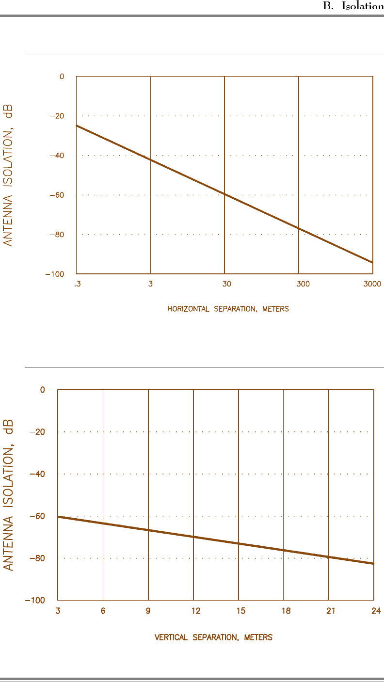
Figure B-1. Antenna Isolation versus Horizontal Separation
Figure B-2. (Dipole) Antenna Isolation versus Vertical Separation
AMPS EAC-2000™ Manual: Appendices (27-7658-3, 12/95) Page B-5

(Continued)
Higher isolations for a given antenna separation are possible where
directional antennas are used and their coverage patterns do not
overlap. Metal towers often give better isolation than wooden
poles when directional antennas are mounted on opposite sides of
the tower. Note that reflections from nearby structures (within
several hundred feet) become predominant when trying to achieve
isolation in excess of 80 dB.
The following list illustrates some of the antenna installation
techniques that may be used to optimize antenna isolation. Figure
B-3 depicts a typical tower-mounted antenna installation.
1. Place the antennas vertically in-line on the mounting structure
to take full advantage of the deep nulls off the ends of high-
gain vertically polarized antennas.
2. Use high gain antennas. High gain antennas typically have
sharper nulls off the ends of the antenna. The use of a
circular dish-type parabolic reflector donor antenna reduces
the vertical as well as the horizontal beamwidth of the
antenna and thus provides higher isolation to antennas
mounted above or below it than does a partial parabolic
reflector or corner reflector with a single dipole element.
Consider a 60-degree 17 dBd gain sector type antenna over a
partial parabolic antenna with a dipole element as this antenna
typically has a 6–7 degree vertical beamwidth.
3. Consider using a metal antenna support instead of a wooden
pole. Isolations observed on wooden poles have been highly
variable, with some installations having excellent isolation
(particularly with directional antennas for both the mobile
coverage and donor antennas) while others have had poorer
isolation than that achievable on a metal tower. Also,
wooden poles with their attendant antenna installation
arrangements (e.g., wooden cross-arms) are subject to
warpage or out-of-plumb installation. This can seriously tilt
the antennas and cause poor coverage.
Page B-6 AMPS EAC-2000™ Manual: Appendices (27-7658-3, 12/95)
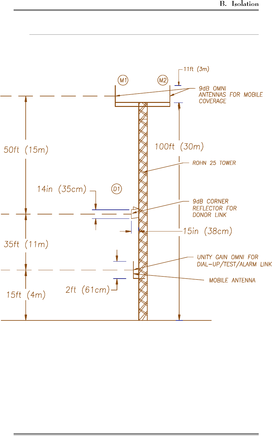
Figure B-3. Tower Mounted Antenna Installation
AMPS EAC-2000™ Manual: Appendices (27-7658-3, 12/95) Page B-7

(Continued)
4. In addition to vertical separation, place the donor and M1/M2
antennas on opposite sides of a metal tower. While this
contradicts technique 1 above somewhat, the presence of the
metal structure between the two antenna systems, while
maintaining vertical separation, can sometimes provide an
additional 10 dB, or more, of isolation.
5. In difficult cases, the use of an ice shield or other metal flat-
screen structure between the vertically separated donor and
M1/M2 antennas can be used to improve isolation. The metal
screen should have bonded joints and be a minimum of 3 feet
(1 meter) square. A 10-feet-square (3-meter-square) screen
gives superior performance, but may prove to be physically
impossible to keep on the tower or pole. The screen should
be mounted 1 to 2 feet (.5 to 1 meter) above the donor
antenna, shielding it from all view of the coverage antennas.
It may be necessary to "fine-tune" the shield placement for
optimum performance.
6. Structures found on the roofs of many buildings can provide
isolation between antennas even if little or no vertical
separation is possible. For example, mount the donor antenna
over the side of the building and mount the coverage
antennas at the other side of the roof, preferably with a
penthouse or elevator shaft between. Sometimes a penthouse,
especially if it is of metal construction, can give sufficient
isolation by itself. If construction is of wood or block, metal
sheeting may be placed on the inside or outside walls to
increase isolation.
7. Very high isolations can be achieved by using earth as the
blocking medium. Isolations in excess of 130 dB have been
reported for tunnel applications.
Nearby structures, such as other towers or
buildings, can degrade antenna isolation if both
antennas are exposed to reflections from these
structures.
Page B-8 AMPS EAC-2000™ Manual: Appendices (27-7658-3, 12/95)
When separation alone cannot give the required isolation, it is
necessary to use attenuators in the donor signal path. Attenuators,
or "pads," will increase isolation dB for dB. That is, a 10 dB
pad will improve the isolation by 10 dB.
Although a -75 dBm donor input level is specified, this includes a
10 dB fade margin which is seldom needed on the point-to-point
paths found in typical EAC-2000 installations. Also, a high D1
input signal level from the donor equates to a high signal level
being sent back to the donor from the EAC-2000. This can cause
the cell site to make power control decisions based on EAC signal
strength, which could cause dropped calls.
In view of the above, the following attenuation guidelines are
recommendations:
• With donor signal > -65 dBm, use a 10 dB or greater pad at
the D1 duplexer ANT port. Aim for donor RSSI of -75 dBm
± 5 dBm
• With donor signal < -65 dBm but > -76 dBm, use a 10 dB
pad at the D1 duplexer LOW port. Donor signal levels (after
the pad) should not fall below -85 dBm. If the signal levels
may fall below -78 dBm, the Donor RSSI release threshold
must be reset to -90 dBm.
If interference or cross-connected calls still persist after all
attempts at improving antenna isolation (either physically or
artificially with attenuators) have been exhausted, the following
suggestions may yield further improvement:
• Interference due to the transmitter noise floor can be reduced
by increasing the separation between the donor and boosted
channel sets. Increasing the separation to at least 6 and no
more than 11 channels will help many stubborn cases.
AMPS EAC-2000™ Manual: Appendices (27-7658-3, 12/95) Page B-9
(Continued)
• If short noise bursts or cross-connected calls due to hand-off
PA intermod are reported, they can be eliminated by adopting
an alternating boosted channel set spacing. That is, instead of
setting the boosted channel set spacing to the same increment
(usually 21) as the donor, alternate the channel spacing on a
20-22-20-22-20 channel basis. This will move any locally
generated intermodulation products off the channels that are
being received from the donor.
B.3 How to Measure Antenna Isolation
Antenna isolation is most effectively measured using a spectrum
analyzer with tracking generator.
1. Connect the tracking generator output to the end of the
transmission line going to the M1 or M2 antenna.
2. Connect the spectrum analyzer to the end of the transmission
line going to the D1 antenna.
3. Set the tracking generator output at maximum (usually
0 dBm). Use an accessory amplifier, if available, to boost
this output to at least +20 dBm.
4. Set the spectrum analyzer to sweep first the low split and
then the high split. The isolation is then the spectrum
analyzer reading plus the tracking generator output. (For
example, if the spectrum analyzer reads -50 dBm and the
tracking generator output is +20 dBm, the isolation is 70 dB.)
Note that isolation is often frequency dependent, with several
nulls and peaks possible in each band. The highest peak in
either band defines the minimum isolation that is achieved
with this particular antenna configuration. Be sure to
discount any signals being received by the antenna connected
to the spectrum analyzer. Note these signals with the
tracking generator turned off. These signals will likely be
higher than the signal being generated by the tracking
generator and may make measuring the actual isolation
difficult. Also, many spectrum analyzers have difficulty
measuring signals below -60 dBm to -70 dBm
Page B-10 AMPS EAC-2000™ Manual: Appendices (27-7658-3, 12/95)
(Continued)
when sweeping a broad bandwidth. This may limit the ability to
accurately measure isolation unless smaller bandwidths are used.
A second method of measuring isolation uses a signal generator
rather than the tracking generator as the signal source. The signal
generator frequency and amplitude can be manually changed to
avoid conflict with existing strong signals from the donor (and
other) cell sites. The spectrum analyzer sweep bandwidth can also
be narrowed to achieve greater sensitivity for measuring actual
isolation. The signal generator should be manually swept through
both the low split and the high split bands to determine the
minimum isolation point.
A third method to measure isolation uses the EAC-2000 itself as
the signal source and is relatively simple to accomplish with a
spectrum analyzer and the following procedure. (This procedure
should be done after the unit is programmed and the combiner is
tuned.)
1. Connect the D1 antenna feedline to a spectrum analyzer.
2. Go into SET and select menu B, Power Amplifiers.
3. Key up PA 1 through PA 11 in sequence and note the level
on the spectrum analyzer for each channel. Also note the PA
power reading in dBm.
4. Calculate the isolation:
Isolation = PA dBm -3 dB (combiner/duplexer loss) - D1 dBm.
Since this D1 dBm measurement is a negative number, this
can be simplified:
Isolation = PA dBm + |D1 dBm| -3
AMPS EAC-2000™ Manual: Appendices (27-7658-3, 12/95) Page B-11
(Continued)
PA dBm = 46, D1 dBm = -30, |D1 dBm| = 30
Isolation = 46 +30 -3
Isolation = 73 dB
5. Take the highest readings obtained from PAs 1–5 and 7–11 to
calculate an isolation value for the M1 antenna. Take the
readings from PA 6 to calculate the isolation value for the
M2 antenna. To get a more accurate reading of isolation on
the M2 antenna, we recommend temporarily exchanging the
M1/M2 antenna connections and rereading the values
received when keying PAs 1–5 and 7–11.
Page B-12 AMPS EAC-2000™ Manual: Appendices (27-7658-3, 12/95)
$SSHQGL[&
5HIHUHQFH2VFLOODWRU$GMXVWPHQW
C.1 Adjusting the Reference Oscillator (If Needed)
The EAC-2000 contains a crystal-based reference oscillator. The frequency
calibration of the reference oscillator is trimmed as close as possible at the
factory and .
However, like all crystals, the oscillator exhibits an aging characteristic, and
the calibration may drift over time. To maintain the specified accuracy over
time, the frequency of the EAC-2000 boosted control channel should be
checked periodically and adjusted, if necessary, to compensate for long-term
aging.
Do NOT use voice channels as a basis for frequency adjustment,
since the EAC-2000 oscillator accuracy contributes only a small part of the
accuracy on voice channels.
There are two approved vendors for the oscillator. The
following shows a typical adjustment session for one of them.
The procedure for the other vendor merely uses T8 in place of
T7 in the following sequence.
The easiest way to tell which vendor oscillator is installed is
simply to try one. If the software indicates "acknowledge
errors," or if the frequency does not move, then use the other.
At the command entry level prompt >:
RFC<CR> TYPE "H" FOR HELP
#T7<CR> TRIMMING POT 7
ENTER C, U or D (Center, Up, or
Down); RET when finished:
CUUUUUDDU<CR> (no response)
#<ESC> >
AMPS EAC-2000™ Manual: Appendices (27-7658-3, 12/95) Page C-1
(Continued)
The pot should be centered any time an adjustment is made.
This not only centers the pot, but also ensures that the
software and hardware variables are initialized properly. This
may actually cause the frequency to move several parts off.
If the frequency seems to be very far off,
especially at installation time, be sure the measurement
equipment you are using is calibrated accurately.
The U’s and D’s may then be used to trim it back in.
Page C-2 AMPS EAC-2000™ Manual: Appendices (27-7658-3, 12/95)

*ORVVDU\DQG,QGH[
27-7659-2
Issue 12/95
© Copyright 1995 Allen Telecom Systems
All Rights Reserved

*ORVVDU\
AMPS – Advanced Mobile Phone System. Cellular standard that provides compatible operation
in the 824–849 and 869–894 MHz band.
Boost – To receive, amplify, and reradiate signals to fill in weak coverage areas.
Boosted Control Channel – The control channel used between the booster and the mobiles in the
booster coverage area (a different frequency than the donor control channel).
Booster – A system that boosts or repeats.
Booster Coverage Area – The area where subscribers obtain coverage through the booster.
Booster Link Channel – A dedicated channel in an EAC-2000 in Multi-hop configuration. When
the EAC-2000 responds to a call, it transmits a continuous data message over the booster link
channel, which the next booster in the chain decodes in order to identify the channel on which the
call is boosted.
Command Entry Level – The level at which the software system accepts three-letter commands.
Indicated by the prompt character >.
D1 Antenna – The primary antenna facing the donor cell site, used for reception of control and
voice channel signals from the donor cell site and for transmission of control and voice signals
back to the cell site.
Donor Cell Site – The cell site in communication with the booster.
Donor Control Channel – The control channel used between the cell site and the booster (and all
the mobiles in direct contact with the cell site).
EAC-2000™ – The trademarked name for a booster made by Allen Telecom Systems.
Forward Path – The path taken by the RF signal transmitted by the donor cell, which is received,
amplified, and reradiated by a booster and received ultimately by a subscriber in the booster
coverage area.
Grab-back Message – A second voice channel assignment message sent to a mobile leaving the
booster coverage area, directing the mobile to come back to the boosted voice channel. If the
donor's signal is stronger, the mobile will ignore the grab-back message; if the EAC-2000 signal
is stronger, the mobile will come back to the boosted voice channel.
Hand-back Threshold – Signal level at which a mobile being boosted becomes a candidate for
returning to the original donor site voice channel. This threshold is set as an operating parameter
for the individual system.
AMPS EAC-2000™ Manual: Glossary and Index (27-7659-2, 12/95) Glos-1

Hand-in Threshold – Signal level at which a mobile on one of the donor voice channels becomes
a candidate for boosting. This threshold is set as a parameter for the individual system.
Hand-off – The process of transferring a boosted call back to the donor cell or to another booster
or cell.
Inactivity Timeout – A programmable period of time after which, if no keyboard entries have
been received, the EAC-2000 software system will terminate any running commands and end the
session.
M1 Antenna – Primary antenna facing the mobiles in the booster coverage area. Used for
transmission of the boosted control channel and boosted voice channels to the mobiles, and for
diversity reception from the mobiles.
M2 Antenna – Secondary antenna facing the mobiles in the booster coverage area, used for
sending hand-off messages to the mobiles and for diversity reception from the mobiles.
Mobile Antenna – Antenna for the installed cellular mobile facing the donor cell site.
Modem Mobile MIN – Assigned mobile identification number of the mobile cellular telephone.
Multi-hop Operation – Two or more EAC-2000 units set up to operate together in a line to
provide seamless cellular coverage (e.g., along a traffic corridor). Each booster in the line
communicates with the previous and next unit.
PA – Power Amplifier
Primary Donor Cell – When a booster is adjacent to several cell sites, the control channel of the
cell with the best signal is chosen as the donor control channel, and this cell is referred to as the
primary donor cell.
Remote Link – Modem link between the EAC-2000 and another terminal. The remote terminal
may be used to exercise the system.
Repeater – Synonymous with booster, usually applied to boosters that translate frequencies. The
EAC-2000 is type-accepted as a repeater.
Reverse Path – The path taken by the RF signal transmitted by a subscriber mobile in the booster
coverage area, which is received, amplified, and reradiated by a booster and received ultimately
by the donor cell site.
RSSI – Received Signal Strength Indicator.
SAT – Supervisory Access Tone.
Glos-2 AMPS EAC-2000™ Manual: Glossary and Index (27-7659-2, 12/95)

,QGH[
Bold Roman
numerals indicate volume
numbers.
Accessories, III: 3-4
replacing, Apps.: Parts-1 to -5
ac
breaker locations, I: 4-3, 4-4
connections, I: 3-5
(See also Power)
ALA. (See Command(s))
Alarm report. (See Command(s), ALA)
Alarm(s), Apps.: A-23
connecting external, I: 3-7 to -9, III: 3-3
critical, I: 4-23 to -24, 5-5, II: 2-11, 2-58
log only, I: 4-24
programming, I: 4-19 to -24
RSSI, II: 2-11
(See also individual alarms—e.g., PA
alarms)
Amplifiers. (See Control channel amplifiers,
PAs, Voice channel amplifiers)
Antenna(s)
connectors, illustrated, I: 3-6
D1, I: 1-7,2-4,2-5,2-6,2-7,2-9, III: 2-3
installation, illustrated, I: 2-8, Apps.: B-7
installing, I: 3-6, Apps.: B-6 to -12
isolation, I: 2-6, 2-7 to -8, 3-6, 7-3,
Apps.: B-4 to -10
M1/M2, I: 2-4, 2-5, 2-6, 2-7, III: 2-3
mobile, I: 2-4, 2-5, 2-6, 2-7, III: 2-3
placement/location of, I: 2-2, 2-6
return loss low alarm point, II: 2-10, 2-50
separation, I: 2-6
types, I: 2-4 to-5, III: 2-3
Auto-dial
delay between retries, II: 2-6, 2-32
dial-up phone numbers, II: 2-6, 2-30
enable, II: 2-5, 2-29
max trial period, II: 2-6, 2-32
trials max, II: 2-6, 2-31
Backplane. (See EAC-2000,
diagrams, System boards)
Back-up control channel option, II: 2-4, 2-22
Baud rate. (See Modem—setup, local port,
remote port)
Block diagram. (See EAC-2000, diagrams)
Boards. (See System boards)
Boosted control channel(s), II: 2-4, 2-20,
III: 2-1
defined, I: 1-3
Boosted control channel(s) (Continued)
selecting, I: 2-12, 7-4 to -5
setting, I: 4-16
Boosted voice channel(s), II: 2-5, 2-27
defaults, II: 2-5
selecting, I: 2-16, 7-4 to -5
setting, I: 4-19
Booster link channel, I: 4-15, 8-5, II: 2-4,
2-24
- previous EAC, I: 4-15, II: 2-5, 2-24
Breaker. (See ac)
Burse noise, Apps.: A-26
Cabinet
footprint, illustrated, I: 3-4
size, I: 2-3, III: 3-1
Call processing
described, I: 5-4 to -6III: 2-10 to -13
parameters, II: 2-9
problems, Apps.: A-10
recommendations, II: 2-9
Card cage wiring diagram. (See EAC-2000,
diagrams)
Cellular boosters
operation, illustrated, III: 1-2
use of, III: 1-2
Channel(s)
assignment, III: 1-3
for combined multi-cab/-hop/-donor
operation, I: 10-2
selecting, I: 2-11
(See also Control channel(s); Directed
retry channels)
Combined operation. (See Multi-cabinet,
Multi-hop, Multi-donor)
Combiner
cavity, illustrated, I: 4-27
reverse, III: 2-8
tuning, I: 4-26 to -30
Command(s)
ALA, I: 4-13, II: 3-14 to -19
basic, I: 4-7 to -10
DCH, II: 3-27 to -28
AMPS EAC-2000™ Manual: Glossary and Index (27-7659-2, 12/95) Index-1

Command(s) (Continued)
DCS, II: 3-20 to -26
entering, I: 4-8, II: 1-6 to -8
listed, I: 4-9, II: 1-9
LOC, I: 4-10, II: 1-8
MIN, II: 3-30 to -31
Command(s) (Continued)
PWR, II: 3-12
RES, I: 4-8, 4-10, II: 1-8
REV, II: 3-32
RSS, II: 3-9 to -10
SAT, II: 3-13
SCS, II: 3-5 to -8
SET, I: 4-8, II: 2-1 to -60
special, II: 4-1 to -2
SSR, I: 4-9, II: 3-11
SSS, I: 4-13, II: 3-1 to -4
syntax, I: 4-7, II: 1-6
system monitoring, II: 3-1 to -32
TIM, I: 4-32, II: 3-29
Communication parameters. (See
Modem—setup, Local port, Remote
port)
Compliance with standards, III: 3-4
Console timeout, II: 2-5, 2-29
Continuous cycles, escaping from, I: 4-8,
II: 1-8
Control channel(s)
amplifiers, III: 2-1
boosting, I: 1-5
parameters, II: 2-4
response, I: 7-1, III: 2-14 to -15
RF board to use for, II: 2-4, 2-20
state during "all channels busy",
II: 2-4, 2-21
(See also Boosted control channel(s);
Donor control channel(s); Revertive
control channel; Substitute control
channel)
Controller board. (See System boards)
Critical alarm(s). (See Alarms)
Cross-talk, Apps.: A-21
D1. (See Antenna(s))
DCH. (See Command(s))
DCS. (See Command(s))
Delay between hand-in attempts.
(See Hand-in)
Dial command. (See Modem—setup)
Dial prefix string (See Modem—setup)
Dial-up phone numbers. (See Auto-dial)
Directed retry channels, I: 2-14, 4-15,
II: 2-4, 2-22
setting, I: 4-16
Disconnect parameters, II: 2-9
Donor control channel(s), I: 1-6, 4-24,
II: 2-4, 2-19, III: 2-11
defined, I: 1-3
identifying, I: 2-11
Donor control channel(s) (Continued)
RSSI, alarm points, I: 4-24, II: 2-59
setting, I: 4-15
(See also Control channel(s))
Donor RSSI, II: 2-9, 2-46
Donor voice channel(s)
identifying, I: 2-15 to -16
lists, I: 1-6, II: 2-5, 2-26 to -27, III: 2-11
RSSI, high alarm point, I: 4-24, II: 2-60
setting, I: 4-17 to -18
Doors, securing, I: 3-5
Dropped calls, Apps.: A-6, A-14, A-18,
A-20
Dynamic forward power control algorithm,
II: 2-52
EAC-2000
answering, I: 5-4
combined with EAC-IVs, I: 7-4
concept, III: 2-1 to -2
diagrams, end of Vol. 3
illustrated, I: 3-2, 3-3, III: 3-6, 3-7, 3-8
operation, I: 1-4 to -7, II: 1-2 to -5,
III: 2-3 to -5
originating, I: 5-5
specifications, III: 3-1 to -3
Environment, III: 3-1
Equipment characteristics, III: 3-4 to -5
Erratic operation of EAC-2000, Apps.: A-23
External alarms/controls. (See Alarms)
Fan activation. (See PA, temperature)
Figures, listed, I: vi, II: vi, III: v
Footprint. (See Cabinet)
Forward PA
power low alarm point, II: 2-3, 2-15
power step, II: 2-3, 2-15
(See also Key forward PA)
Forward path, I: 1-2, 1-4, III: 2-4
defined, I: 1-3
Frequency allocation, I: 1-4, III: 1-3
Gain, III: 3-2
Grab-back, I: 1-7, III: 2-12
Index-2 AMPS EAC-2000™ Manual: Glossary and Index (27-7659-2, 12/95)

Hand-back, I: 1-6, III: 2-12
max num attempts per call, II: 2-9, 2-47
min delay between attempts, II: 2-9, 2-48
mobile power step, II: 2-8, 2-43
Hand-back/grab-back control, II: 2-9, 2-49
Hand-back threshold(s), II: 2-8, 2-43,
III: 2-12
determining, I: 6-1
setting, I: 6-2
setting for Multi-hop, I: 7-5 to -7
Hand-in, III: 2-11
delay between attempts, II: 2-8, 2-45
excessive, Apps.: A-15
mobile power step, II: 2-8, 2-43
none (troubleshooting), Apps.: A-16
Hand-in threshold(s), II: 2-8, 2-41
determining, I: 6-1
setting, I: 6-2
Hand-off(s)
cellular system, Apps.: A-7
messages, III: 2-5
noise bursts, Apps.: A-26
to a new cell, III: 2-13
Hang-up string (See Modem—setup)
Hardware installation, I: 3-1 to -10
Inactivity timeout, I: 4-10, II: 1-8
Initialization string (See Modem—setup)
Inputs/outputs
alarm states, II: 2-10
electrical specifications for, I: 3-8
external analog, II: 2-55
external digital, II: 2-56, 2-57
typical wiring for, I: 3-9
Interchangeability of equipment, III: 3-4
Interface specifications, III: 3-3
Isolation
achieving, Apps.: B-4 to -9
measuring, I: 2-9, Apps.: B-10 to -12
need for, Apps.: B-3
Key forward PA, II: 2-3, 2-16
Key reverse PA, II: 2-3, 2-16
Local link, III: 2-16
establishing, II: 1-2 to -3
Local port
baud rate, II: 2-7, 2-35
comm params, II: 2-7, 2-36
Locking onto control channel, Apps.: A-29
Log only alarms (See Alarms)
M1, M2. (See Antenna(s))
Main harness wiring diagram. (See
EAC-2000, diagrams)
MDU (See Multi-donor operation)
Mechanical
installation, I: 3-4 to -5
specifications, III: 3-1
Menu(s)
Alarms, II: 2-50
Call Processing Parameters, II: 2-48
Control Channels, II: 2-19
Menu(s) (Continued)
Critical Alarms, II: 2-58
Disconnect Control, II: 2-46
External Analog Inputs, II: 2-55
External Digital Inputs, II: 2-56
External Digital Outputs, II: 2-57
Modem Control, II: 2-28
Power Amplifiers, II: 2-14
RF Board Position, II: 2-13
RF boards, II: 2-12
SET Main, II: 2-12
SET, using, I: 4-11, II: 1-7
SET menu map, I: 4-12, II: 2-2
Site ID, II: 2-17
System Parameters, II: 2-17
Thresholds and Power Control, II: 2-40
Voice Channels, II: 2-25
Microcontroller, III: 2-6
MIN. (See Command(s))
Mobile
antenna (See Antenna(s))
checking out, I: 5-2
dynamic power control threshold, II: 2-8,
2-41
power control causes PA power
cutback, II: 2-10, 2-53
power step, I: 4-25, II: 2-6, 2-39
programming, I: 5-2
RSSI > threshold, II: 2-9, 2-49
shelf, III: 2-9 (See also EAC-2000,
diagrams)
setting up service, I: 5-2
Modem, III: 3-5
control parameters, II: 2-5 to -6
equipment, I: 5-1
erratic operation, Apps.: A-22
mobile MIN, I: 4-25, II: 2-6, 2-38, 3-30
mobile power step, II: 2-6, 2-39
setup parameters, II: 2-6 to -7
setup strings, II: 2-6, 2-33 to -35
AMPS EAC-2000™ Manual: Glossary and Index (27-7659-2, 12/95) Index-3

Mounting
the cabinet, I: 3-4
surface, I: 2-4
Multi-cabinet operation, I: 10-1 to -3
Multi-donor activation threshold, I: 8-2, 8-4,
II: 2-8, 2-42, III: 2-14
Multi-donor operation, I: 1-6, 2-1, 2-6,
8-1 to -4, III: 2-13
installing EAC-2000 for, I: 8-2
with Multi-cabinet/-hop, I: 10-1 to -3
Multi-hop operation, I: 2-2, 2-6, 4-13,
7-1 to -8, II: 2-4, 2-18,
III: 2-14 to -15
Multi-hop operation (Continued)
enabling, I: 7-3 to -4
installing EAC-2000 for, I: 7-2 to -8
with Multi-cabinet/-donor, I: 10-1 to -3
selecting boosted channels for, I: 7-4
Noise, Apps.: A-27
Optimizing performance, I: 6-1 to -2
Output power, setting, I: 4-26 to -31
Outputs. (See Inputs/Outputs)
Parameter(s)
alarm, II: 2-10 to -11
initial, I: 4-13 to -25
power amplifier, II: 2-3
RF board, II: 2-3
summaries, II: 2-3 to -11
system, II: 2-4 to -9
Parts, ordering, Apps.: Parts-1 to -5
PA(s)
45-watt, III: 2-8
cage wiring diagram. (See EAC-2000,
diagrams)
to antenna loss - high alarm point,
II: 2-10, 2-51
interface board, III: 2-9
power levels, adjusting, I: 4-26 to -30
power potentiometer, illustrated, I: 4-28
setting power low alarm points, I: 4-31
temp - fan activation point, II: 2-10, 2-51
temp - high alarm point, II: 2-10, 2-51
temp - PA power cutback point, II: 2-10,
2-52
Password(s), I: 4-25, II: 2-5, 2-28 to -29
bypassing, I: 1-3
Pin out, external alarm/control connector,
I: 3-7
Power
class. (See Station power class)
control parameters, II: 2-8, 2-40 to -45
cutback point. (See PA, temp)
levels (See PAs)
output, III: 3-2
service requirements, I: 2-3
specifications, III: 3-1
(See also ac connections)
Power supply
described, III: 2-9
shelf wiring diagram, III: 3-10
voltage parameters, II: 2-10, 2-53 to -54
Powering up/down, I: 4-3
Preamplifiers, III: 2-8
Primary donor cell, I: 1-7, III: 2-10, 2-11
PWR. (See Command(s))
Quick start procedures, I: ix
Reference oscillator adjustment,
Apps.: C-1 to -2
Regulator module, III: 2-9
wiring, illustrated, III: 3-9
Reliability, III: 3-5
Remote link, III: 2-16
EAC-2000 answering, I: 5-3
EAC-2000 originating, I: 5-4
establishing, II: 1-4 to -5
installing, I: 5-1 to -6
testing, I: 5-4 to -6
Remote port
baud rate, II: 2-7, 2-36
comm params, II: 2-7, 2-37
handshake, II: 2-7, 2-38
Report values, setting, I: 4-32
Reports/readings, examples
ALA, II: 3-15
DCH, II: 3-28
DCS, II: 3-21
MIN, II: 3-30
PWR, II: 3-12
RSSI, II: 3-9
SAT, II: 3-13
SCS, II: 3-5
SSS, II: 3-2
TIM, II: 3-29
REV. (See Command(s))
Reverse PA
power low alarm point, II: 2-3, 2-16
power set, II: 2-3, 2-15
(See also Key reverse PA)
Index-4 AMPS EAC-2000™ Manual: Glossary and Index (27-7659-2, 12/95)

Reverse path, I: 1-3, 1-4, III: 1-2, 2-4
setting output power, I: 4-30
Revertive control channel option, I: 2-12,
II: 2-4, 2-23, 3-25
RF board(s), III: 2-6
diversity, II: 2-3, 2-14
status, II: 2-3, 2-13
to use for control channel, II: 2-4, 2-20
RF specifications, III: 3-2
RSS. (See Command(s))
RSSI, III: 3-2
alarm points, II: 2-11, 2-59
averaging speed, II: 2-8, 2-44
(See also Donor RSSI, Mobile RSSI,
Donor control channel(s), Donor voice
channel(s))
SAT
fade timeout, II: 2-9, 2-47
(See also Command(s))
SCS. (See Command(s))
Separation of antennas, I: 2-6, 3-6,
Apps.: B-4 to -6
(See also Antenna(s))
Service
for mobile, setting up, I: 5-2
skills required , III: 3-5
SET, II: 2-1 to -60
exiting, I: 4-11, II: 1-7
menu map, I: 4-12, II: 2-2
moving through menus, I: 4-11, II: 1-7
Set defaults feature, II: 2-60
Setups, unsuccessful, Apps.: A-18
Signal level/strength, I: 2-6, 3-7, 7-3
at MDU, I: 8-3
measuring, I: 2-9 to -10
weak, from donor, Apps.: A-6
Site
ID, I: 4-14, II: 2-4, 2-18
requirements, I: 2-2 to -4
Space recommendations, I: 2-3
Specifications, III: 3-1 to -4
SSS. (See Command(s))
Start-up procedures. (See Quick start)
Station power class selective boosting,
II: 2-8, 2-45
Substitute control channel, I: 2-13, 4-15,
II: 2-4, 2-23
SYN LOC alarms, Apps.: A-23
System boards, III: 2-6 to -9
backplane, III: 2-7
controller, III: 2-7
PA interface, III: 2-9
(See also RF boards)
System status, I: 4-13
Talk-back range, Apps.: A-11
Temperature. (See PA, temperature)
Terminal
connecting, I: 4-5
location of connector, illustrated, I: 4-5
Threshold(s)
parameters, II: 2-8, 2-40 to -45
programming, I: 4-19 to -24
TIM. (See Command(s))
Time values, setting, I: 4-32
Transmitter combiner. (See Combiner)
Transmitter output noise, Apps.: A-28
Troubleshooting, Apps.: A-1 to -27
Voice channel(s)
amplifiers, III: 2-2
boosting, I: 1-5
parameters, II: 2-5
(See also Boosted voice channel(s);
Donor voice channel(s))
Warranty, iii
Wiring diagrams. (See EAC-2000, diagrams)
AMPS EAC-2000™ Manual: Glossary and Index (27-7659-2, 12/95) Index-5
3DUWV$FFHVVRULHV
2UGHU,QIRUPDWLRQ
This section provides procedures for ordering or exchanging parts and accessories, a
list of replaceable assemblies for the EAC-2000™, and reference drawings. Warranty
information is given in the front of this manual.
Construction is comprised of machine-placed surface
mount components. Special factory test fixtures are required for repair.
Replacing Parts and Accessories
To order spare or replacement assemblies, refer to the following instructions:
Failed EAC-2000 parts or assemblies that are still under the manufacturer’s
warranty can be exchanged by following these procedures:
1. Obtain the EAC-2000 serial number. The serial number is labeled on each
of the system components.
2. Call the Extend-A-Cell Hotline: (800) 800-EAC4 (3224) or 216-349-8413.
Be prepared to supply the unit serial number and any other pertinent
information. Refer to the following parts list and reference drawings to
identify specific parts and their locations.
3. Repair parts/assemblies will be shipped. Allen Telecom Systems will ship
replacement parts or assemblies with a Return Materials Authorization
form. This form must be used to return failed parts or assemblies to Allen
Telecom Systems. All parts are shipped next day air, free of charge,
unless otherwise instructed by the customer.
4. Return failed parts/assemblies to Allen Telecom Systems according to
instructions on the Return Materials Authorization form.
AMPS EAC-2000™ Manual: Parts & Accessories (27-7660-1, 1/95) Parts-1
Selected EAC-2000 parts or assemblies that are no longer under warranty can
be replaced through Allen Telecom Systems’ exchange program. This program
permits customers to exchange a failed part or assembly for a working part or
assembly, for a nominal charge. Contact Allen Telecom Systems, Systems
Engineering Department, to determine which parts and assemblies can be
exchanged under this program.
To take advantage of this program, follow the procedures listed above under I.
Exchange Procedures: Units Under Warranty.
Spare parts for the EAC-2000 can be purchased by contacting Allen Telecom
Systems, Customer Service Department at or
for prices and delivery. Refer to the following list and illustrations to identify
specific parts and their locations.
Parts-2 AMPS EAC-2000™ Manual: Parts & Accessories (27-7660-1, 1/95)
Replaceable Parts/Assemblies for EAC-2000
The following list includes service parts/assemblies that are frequently purchased as
spares and is not inclusive of all parts/assemblies that are available for the EAC-2000.
Items not included in this list may be ordered by contacting Allen Telecom Systems
Customer Service Department.
1 19-5612-1 Reverse Combiner Module
2 19-5598-1 Controller Board
3 19-5838-1 D1 Duplexer
4 19-5613-1 Forward Preamp Module
5 19-5599-1 RF Board
6 21-117-1 45-Watt Power Amplifier
7 19-5588-1 PA Interface Board
8 19-5627-1 Power Sensor
9 59-12-1 28 Vac Power Supply
10 19-5620-1 Regulator Module
11 19-5614-1 Reverse Preamp Module
AMPS EAC-2000™ Manual: Parts & Accessories (27-7660-1, 1/95) Parts-3
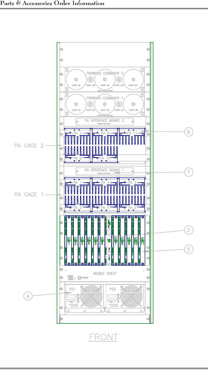
Reference Drawings
Parts-4 AMPS EAC-2000™ Manual: Parts & Accessories (27-7660-1, 1/95)
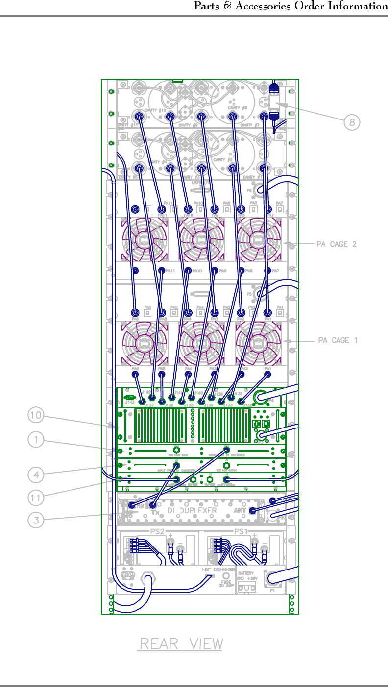
Reference Drawings (Continued)
AMPS EAC-2000™ Manual: Parts & Accessories (27-7660-1, 1/95) Parts-5