Andrew Wireless Innovations Group BCEL-1915BA TFB 1915 BOOSTER AMP User Manual MN004 00
Andrew Wireless Innovations Group TFB 1915 BOOSTER AMP MN004 00
USER GUIDE

OPERATIVE ANDOPERATIVE AND
MAINTENANCEMAINTENANCE
HANDBOOKHANDBOOK
Copyright 1998Tekmar Sistemi S.r.l.
All Rights Reserved

Rel 00 08/04/98 BriteCell Dual Band Operative and maintenance Handbook
Tekmar Sistemi S.r.l. keeps the right of any change or improvement without prior notice. Pag.2/15
SYSTEM: BRITECELL Class 1 (High Dynamic Range)
OPERATING BAND: Rel.00-980408
¨ AMPS 800 + DCS 1800
¨ AMPS 800 + PCS 1900
¨ GSM 900 + DCS 1800
¨ GSM 900 + PCS 1900
INDEX
1. DECLINE OF RESPONSIBILITY.................................................................................... 3
2. CONFORMITY DECLARATION ..................................................................................... 4
3. INSTALLATION CONDITIONS....................................................................................... 5
4. ASSISTANCE AND WARRANTY CONDITIONS............................................................ 6
5. WARNING LABELS........................................................................................................ 7
6. SYSTEM THEORY ......................................................................................................... 8
7. TECHNICAL DETAILS ................................................................................................... 9
7.1 OPTICAL CONNECTORS......................................................................................... 9
7.2 LOCAL INTERFACE.................................................................................................. 9
7.2.1 6HE SUBRACK TPR912............................................................................................................. 9
7.2.2 PLUG IN LOCAL INTERFACE MODULE.................................................................................... 9
7.2.3 STANDALONE LOCAL INTERFACE UNIT............................................................................... 10
7.2.4 TFL BSI .................................................................................................................................... 11
7.2.5 CROSSBAND COUPLER TLC2501.......................................................................................... 11
7.2.6 2-WAYS RF COMBINER TLC 2502/TFL-UDD.......................................................................... 11
7.2.7 3-WAYS RF COMBINER TLC 2503.......................................................................................... 11
7.2.8 PAGER DL COMBINER TLC-DB.............................................................................................. 11
7.3 REMOTE RF OPTICAL TRANSCEIVER................................................................. 11
7.3.1 PAGER REMOTE PANEL ACTIVE ANTENNA TPA320 ........................................................... 12
7.3.2 MINIPANEL ANTENNA TPA302............................................................................................... 12
7.3.3 FLAT PANEL MULTIBAND ANTENNA TPA 3020..................................................................... 12
7.3.4 DOWNLINK AGC ..................................................................................................................... 12
7.3.5 UPLINK GAIN SETTING........................................................................................................... 12
7.3.6 POWER SUPPLY..................................................................................................................... 13
8. INSTALLATION HINTS ................................................................................................ 14
8.1 INSTALLATION OF LOCAL INTERFACE ............................................................... 14
8.2 INSTALLATION OF REMOTE RF OPTICAL TRANSCEIVER ................................ 14
9. POWER LEVELS.......................................................................................................... 14

Rel 00 08/04/98 BriteCell Dual Band Operative and maintenance Handbook
Tekmar Sistemi S.r.l. keeps the right of any change or improvement without prior notice. Pag.3/15
1. DECLINE OF RESPONSIBILITY
This handbook provides all necessary information about the device, namely:
• installation
• usage and possible problem solving
• maintenance
Tekmar Sistemi advises the accurate reading of this handbook and the respect of the
operating instructions given here below, in order to get all necessary information for a
correct installation, usage and maintenance of the device.
Tekmar Sistemi declines all responsibilities with respect to any possible damage due to
an inappropriate usage of this handbook, or to a non-compliance of the rules set up in this
handbook.

Rel 00 08/04/98 BriteCell Dual Band Operative and maintenance Handbook
Tekmar Sistemi S.r.l. keeps the right of any change or improvement without prior notice. Pag.4/15
2. CONFORMITY DECLARATION
Tekmar Sistemi S.r.l. DECLARES :
that the device related to this usage and maintenance handbook comply with the CE
mark requirements, according to the Low Tension Rules 73/23/CEE and Electro-magnetic
compatibility Rules 89/392/CEE , and particularly with the following laws and rules :
EN Rules
IEC Rules
Tekmar Sistemi will carefully retain the technical file related to the device design, together
with this usage and maintenance handbook, for a minimum time span of 10 years.
Signature : Legal Representative of Tekmar Sistemi S.r.l.

Rel 00 08/04/98 BriteCell Dual Band Operative and maintenance Handbook
Tekmar Sistemi S.r.l. keeps the right of any change or improvement without prior notice. Pag.5/15
3. INSTALLATION CONDITIONS
Environmental Conditions :
Temperature : 5-40°C
Chemical materials : Do not install in corrosive atmosphere or environments, in any
environment with explosive materials or with inflammable
substances ;
Installation site features:
The installation of the rack has to be carried out by proper and competent staff. Besides,
the system is supposed to be used for indoor installation.
The rack has to be positioned in indoor environments, dry and suitable for this purpose,
i.e.:
• no explosion risks is present ;
• the environment is not classified as a high-risk one in case of fire;
• powders in suspension are not to be found in great concentration;
• the environment is not subject to any traffic which could cause crash damages;
• the site is properly located with respect to the ergonomic positioning of the working
environments ;
• the system is placed in a private room, protected against any possible violation .
Connection to the electrical network
The connection to the electrical network has to be carried out following all necessary
precautions , and namely :
• it must be properly made according to the due diligence rules (ex. : CEI rules, IEC
rules, etc.) ;
• in accordance with the rules for the safety against direct or indirect contacts;
• in accordance with the rules for the safety against the overcurrent (short circuit,
overloading);
• in accordance with the rules for the safety against the overtensions;
• the connection is to be carried out by proper and competent staff

Rel 00 08/04/98 BriteCell Dual Band Operative and maintenance Handbook
Tekmar Sistemi S.r.l. keeps the right of any change or improvement without prior notice. Pag.6/15
4. ASSISTANCE AND WARRANTY CONDITIONS
Tekmar Sistemi S.r.l. grants an assistance service for all its products, either under or out of
warranty .
The warranty period for each product is mentioned on the Supply Contract. In case no specific
time period is mentioned, the warranty is supposed to be valid for a time span of 12 months
after the date of the Delivery Note.
The product is to be considered under warranty (according to the Italian D.P.R. 24/05/1988 n.
224) only on occurrence of the following conditions :
a) The warranty period is not expired;
b) The defect is imputable to the product .
The warranty expires if :
• The product shows violations and/or modifications effected by the customer;
• The fault is due to improper use, maintenance or installation.
The Assistance Service at Tekmar Sistemi evaluates if the product can be repaired or if it is
necessary to replace the unit.
In case the product is out of warranty, the customer is supposed to be charged with the
repair/replacement cost, according to the quotation issued by the manufacturer. The
intervention takes place only after the customer has acknowledged the quotation and
authorised the repair.
Before returning the goods, the customer is supposed to give prior notice to Tekmar Sistemi,
which will provide the necessary authorisation.
In order to obtain a fast and proper assistance, the customer should attach to the lot an
accompanying letter, including the following information:
Ref. : Invoice No.
Ref. : Delivery Note
Product References : N° of pieces, Model, Serial Number
Defect report
Tekmar Assistance Service issues a check report which is included in the packing
together with the product being returned.
If any Corrective Action is proposed by the Quality Assurance, the customer is informed
about it via fax.

Rel 00 08/04/98 BriteCell Dual Band Operative and maintenance Handbook
Tekmar Sistemi S.r.l. keeps the right of any change or improvement without prior notice. Pag.7/15
5. WARNING LABELS
Meaning: Attention - Flat polished connector.
Meaning: Attention - Angle polished connector.
Meaning: Attention - possible invisible laser radiation from this aperture -
flat polished connectors.
Meaning: attention - possible invisible laser radiation from this aperture -
angle polished connectors.
Meaning: attention - possible invisible laser radiation, max. power 30mW,
wavelength 1300nm, laser product class III b.

Rel 00 08/04/98 BriteCell Dual Band Operative and maintenance Handbook
Tekmar Sistemi S.r.l. keeps the right of any change or improvement without prior notice. Pag.8/15
6. SYSTEM THEORY
BRITECELL is an RF distribution/concentration system, based on electrical to optical conversion,
and fibre transmission.
It is mainly intended for cellular indoor coverage, because of its intrinsic high dynamic range, and
RF performances.
The DUAL BAND system provides coverage for two bands :one in the 800-1000 MHz range the
other in the 1700-2000 MHz1.
A local interface (composed of 6 plug in local interface modules or of 1 standalone local interface
unit) provides RF connection with BTS and conversion to optical in both UL and DL paths; each
Local interface has a single RF connector per path, while four optical connectors per path are
provided to interface the fibre cables driving the remote units.
The local interface modules can be combined in groups of two or three through one or more RF
combiners, according to the specific coverage and indoor cells design.
The local interface contains the required auxiliary circuitry, including AC mains power supply.
The remote transceivers provide air-interface to coverage area; each of them includes a high-
efficiency surface antenna, RF to optical interface in both UL and DL paths, RF LNA and PA,
control and auxiliary functions, and AC mains power supply.
An auxiliary RF port is available, to additionally connect a passive antenna for better coverage
shaping. The RF combiner is taken as part of the antenna feeder; the related loss is 3.8dB per
arm. The system can be provide with a customised feature (TFAad1H-c/2), which allows an
additional Pager transmit in Down link at 280 ± 5 MHz; it is suited to carry Flex or Pocsag signals.
1 please refer to the specification sheets

Rel 00 08/04/98 BriteCell Dual Band Operative and maintenance Handbook
Tekmar Sistemi S.r.l. keeps the right of any change or improvement without prior notice. Pag.9/15
7. TECHNICAL DETAILS
7.1 OPTICAL CONNECTORS
The system uses FC/APC optical connectors; DO NOT ATTEMPT TO INSERT OTHER
CONNECTORS, OTHERWISE SEVERE DAMAGE MAY OCCUR.
The FC/APC connector is a high precision optical alignment device; it must be handled with care,
to avoid scratches and other mechanical/optical damages that will impair or reduce the system’s
performance.
Do not touch the connector’s tip, and clean it with proper tissues before inserting them into the
sleeve. Do not leave connectors open. In case of better cleaning need, use only pure ethyl
alcohol.
Sleeves can be cleaned by injecting pure gas under pressure.
7.2 LOCAL INTERFACE
Refer to Table 1-2.
Two types of local interfaces are provided: a local interface composed of a 6 HE Subrack
(TPR912), 6 plug in local interface modules and one or more RF combiner, depending on the
system configuration or a standalone local interface.
The plug in interface modules must be handled with care and only by expert people paying
special attention to the optical fibre cables. In case you need to remove a local interface, you
should remove first the right adjacent module (whatever it is) or cover panel.
Local interfaces cannot be placed close to each other; one 7te module is always required.
IMPORTANT: prior to remove or insert any module make sure that power supply is off.
7.2.1 6HE SUBRACK TPR912
It can carry up to 6 Plug in local interfaces and the ancillary parts required by the system
configuration. The TPR912 includes the AC mains power supply, the required auxiliary circuitry
and alarms.
Alarm: a 9 pins sub D connector (male) on rear panel is used. See table 1 for functions and
pinout. All alarms are relay-contacts, where the relays are excited when NOT ALARMED.
If a local interface is not used, its related female connector on the backplane has to be closed by
a replacing male connector, which is provided together with the rack.
7.2.2 PLUG IN LOCAL INTERFACE MODULE
Refer to table 1.
The downlink laser transmitter is internally connected to an optical splitter, which provides four
outputs.
The RF input port (SMA-female) must be connected to the BTS TX path, at the appropriate level
(see specifications), eventually through the appropriate combiners configuration.

Rel 00 08/04/98 BriteCell Dual Band Operative and maintenance Handbook
Tekmar Sistemi S.r.l. keeps the right of any change or improvement without prior notice. Pag.10/15
The uplink optical receivers RF outputs are combined to a single RF port (SMA-female) to be
connected to the BTS RX path, eventually through the appropriate combiners configuration; this
connection might include an appropriate attenuator, not to desensitise or overload the BTS
receivers because of the noise floor and signals amplitude.
The local signalling (front panel) includes a green LED (PWR ON), plus status and/or alarm
LEDs as follows:
Laser transmitter A green LED lights when laser is biased (=).
Each of two red LEDS lights when the corresponding laser's power
decrease under limits and/or bias is not present ( ).
A yellow LED lights when laser has shut-down command (OFF).
Optical receivers A red LED lights if the input optical power is lower than -12dBm ( ).
No adjustments are required at Local Interface Module.
7.2.3 STANDALONE LOCAL INTERFACE UNIT
Refer to table 2.
The downlink laser transmitter is internally connected to an optical splitter, which provides four
outputs.
The RF input port (SMA-female) must be connected to the BTS TX path, at the appropriate level
(see specifications).
The uplink optical receivers RF outputs are combined to a single RF port (SMA-female) to be
connected to the BTS RX path; this connection must include an appropriate attenuator, not to
desensitise or overload the BTS receivers because of the noise floor and signals amplitude.
The local signalling (front panel) includes a green LED (PWR ON), plus status and/or alarm
LEDs as follows:
Laser transmitter A green LED lights when laser is biased (=)
Each of two red LEDS lights when the corresponding laser's power
decrease under limits and/or bias is not present ( ).
A yellow LED lights when laser has shut-down command (OFF).
Optical receivers A red LED lights if the input optical power is lower than -12dBm ( ).
Alarm/controls : a 15 pins sub D connector (Female) on rear panel is used. See table 2 for
functions and pinout. All alarm pins are O/C , low resistance to GND when NOT ALARMED.
No adjustments are required at Local Interface.

Rel 00 08/04/98 BriteCell Dual Band Operative and maintenance Handbook
Tekmar Sistemi S.r.l. keeps the right of any change or improvement without prior notice. Pag.11/15
7.2.4 TFL BSI
The Base Station Interface module TFL-BSI provides the required level optimization between the
Base Station Transmitters and the BriteCell system.
It includes two independently variable attenuators in uplink and downlink.
7.2.5 CROSSBAND COUPLER TLC2501
The TLC2501 Crossband Coupler allows coupling uplink and downlink signals of services in the
lower cellular band (800-1000 MHz) and in the upper cellular band (1700-2000 MHz).
7.2.6 2-WAYS RF COMBINER TLC 2502/TFL-UDD
These devices are based on hybrid two ways couplers, plus resistive attenuators. They provide
RF power splitting or combing for DL and UL paths.
The Downlink RF input must be connected to the TX path at the appropriate level. The two RF
outputs must be connected to the RF inputs - SMA female of the local interface.
The Uplink RF output must be connected to the BTS RX path.
The two RF inputs must be connected to the RF output of the local interface.
7.2.7 3-WAYS RF COMBINER TLC 2503
These devices are based on hybrid three ways couplers, plus resistive attenuators. They provides
RF power splitting or combing for DL and UL paths.
The Downlink RF input must be connected to the TX path at the appropriate level. The three RF
outputs must be connected to the RF input - SMA female of the local interface.
The Uplink RF output must be connected to the BTS RX path.
The three RF inputs must be connected to the RF output of the local interface
7.2.8 PAGER DL COMBINER TLC-DB
This device is a Dual -band coupler for POCSAG pager injection at local interface. It combines a
280 MHz POCSAG pager carrier on the downlink path at the appropriate level. It can be used in
conjunction with TFA2xx1H-x/2 and TPA320, to provide indoor extended coverage of POCSAG.
7.3 REMOTE RF OPTICAL TRANSCEIVER
Refer to Table 3.
This compact unit contains all the required functions. A stainless steel casing protects the
hardware.
Two RF ports and two optical connectors are placed on one side of the case.
When inserting the optical connectors, take care that handling is smooth enough not to damage
the fibre; remove dust cap only immediately before making connections.
A 50Ω termination must be present in the unused RF ports.
An additional SMB-plug connector carries Pager signals and DC to the auxiliary active radiators
TPA320, through the 3m connecting cable (only TFAad1H-c/2).
The TFA ad1H -c(see datasheet "Ordering information - Part number") version is not provided
with the internal antenna. 2 RF-ports are supplied in order to connect 2 external antennas.

Rel 00 08/04/98 BriteCell Dual Band Operative and maintenance Handbook
Tekmar Sistemi S.r.l. keeps the right of any change or improvement without prior notice. Pag.12/15
Two LEDs give local status information (LD1 red, LD2 green) as follows:
LD2 lights when power supply is on.
LD1 lights as resume alarm in case of no optical power at downlink input and/or in case of failure.
The uplink laser is switched on only if downlink optical power is present. In case of any failure, the
laser is switched off.
By this, the unit gives information on its operating status at local interface.
7.3.1 PAGER REMOTE PANEL ACTIVE ANTENNA TPA320
This device contains a power amplifier and a panel active antenna. It provides amplification and
radiation of pager carrier at 280 MHz.
The RF input (SMB-M) must be connected to the Paging RF port through a SMB-F/SMB-F cable.
The power supply is provided through RF cable.
7.3.2 MINIPANEL ANTENNA TPA302
This antenna has been designed for radiation of pager carrier at 280 MHz. It is provided with a
1-meter long N-female connectorised cable.
7.3.3 FLAT PANEL MULTIBAND ANTENNA TPA 3020
This antenna has been intended to include on a compact single element all the needed radiators
of a multiple BriteCell system; it allows to minimise visual impact and installation effort.
It carries on a single, compact radome the high gain radiators for GSM, DCS, PCS, VHF Paging.
7.3.4 DOWNLINK AGC
The AGC function is provided in the downlink path, to maintain a constant link gain versus optical
loss, within the expected range (0 to 3dB).
7.3.5 UPLINK GAIN SETTING
The unit includes an RF attenuator, which has been provided to give flexibility toward coverage
design. In case of closer mobiles forecast, the attenuator can reduce the uplink gain by 5 or 10
dB. Refer as follows for S1 attenuator settings (bits 1,2,3,4):
Bit 4 must be always on.
Bit 1 2 3 4
——————————————————————-
Full gain: 0 0 1 1
5dB reduction: 0 1 0 1
10dB reduction: 1 0 0 1

Rel 00 08/04/98 BriteCell Dual Band Operative and maintenance Handbook
Tekmar Sistemi S.r.l. keeps the right of any change or improvement without prior notice. Pag.13/15
7.3.6 POWER SUPPLY
Power supply is connected via a factory-provided AC cable; the unit complies with EC
safety rules.
Power supply is always on after the cable is connected to mains.
Suited mains voltage is 84 to 264Vac, 50 or 60 Hz for TFA a51H-c (see datasheet "Ordering
information - Part number").
For TFA a11H-c version needs a 15÷28V AC/DC low voltage.

Rel 00 08/04/98 BriteCell Dual Band Operative and maintenance Handbook
Tekmar Sistemi S.r.l. keeps the right of any change or improvement without prior notice. Pag.14/15
8. INSTALLATION HINTS
8.1 INSTALLATION OF LOCAL INTERFACE
Installation of Local Interface is as per standard rules related to fixed base equipment.
IMPORTANT: prior to remove or insert any module make sure that power supply is off
8.2 INSTALLATION OF REMOTE RF OPTICAL TRANSCEIVER
Installation of Remote RF optical Transceivers must be carried effect taking care that the units are
at least 2.5 m above the walking floor; while choosing their position, please remember that
mobiles should not come too close to the antenna.
The unit is intended to be installed on walls, flat or orthogonal; an additional bracket is included to
provide this last possibility.
The installation must provide the correct UP positioning, and cables must be laid so that
accidental damage is prevented.
9. POWER LEVELS
The following table shows BriteCell downlink maximum input and output power as a function of
the number of carriers being used.

Rel 00 08/04/98 BriteCell Dual Band Operative and maintenance Handbook
Tekmar Sistemi S.r.l. keeps the right of any change or improvement without prior notice. Pag.15/15
NUMBER
OF
CARRIERS
Maximum
POUT TFA/carrier (dBm)
Maximum
PIN TFL/carrier (dBm)
Total Input Power
(dBm)
210,00 3,00 6,01
37,67 0,67 5,44
46,67 -0,33 5,69
55,80 -1,20 5,79
65,23 -1,77 6,01
74,70 -2,30 6,15
84,27 -2,73 6,30
93,90 -3,10 6,44
10 3,57 -3,43 6,57
11 3,27 -3,73 6,68
12 3,00 -4,00 6,79
13 2,73 -4,27 6,87
14 2,53 -4,47 6,99
15 2,30 -4,70 7,06
16 2,10 -4,90 7,14
17 1,93 -5,07 7,24
18 1,77 -5,23 7,32
19 1,60 -5,40 7,39
20 1,43 -5,57 7,44
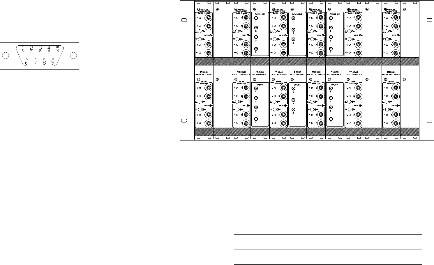
TPR912
ALARMS
INTERFACE CONNECTOR
(SUB D 9 pins male)
PIN 1 NC
PIN 2 COMMON RESUME ALARMS TX
PIN 3 NC
PIN 4 COMMON RESUME ALARMS RX
PIN 5 NC
PIN 6 CLOSED RESUME ALARMS TX OK
PIN 7 OPEN RESUME ALARMS TX OK
PIN 8 CLOSED RESUME ALARMS RX OK
PIN 9 OPEN RESUME ALARMS RX OK
THE SUB D 9 PINS FEMALE IS NOT USED
TABLE1 TPR 912
PLUG IN LOCAL INTERFACE MODULE
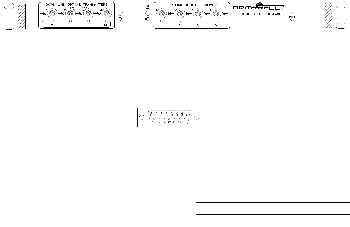
FRONT PANEL TFL X14H
ALARMS / CONTROLS
INTERFACE CONNECTOR
(SUB D 15 pins female)
PIN 1GND
PIN 2TX RESUME ALARM
PIN 3LASER SHUT-DOWN
PIN 4RX RESUME ALARM
PIN 5NC
PIN 6RX 1 ALARM
PIN 7RX 2 ALARM
PIN 8RX 3 ALARM
PIN 9TEMPERATURE ALARM
PIN 10 POWER FAULT ALARM
PIN 11 VAGC RX1
PIN 12 VAGC RX2
PIN 13 VAGC RX3
PIN 14 VAGC RX4
PIN 15 RX 4 ALARM
TABLE 2 STANDALONE UNIT
LOCAL INTERFACE
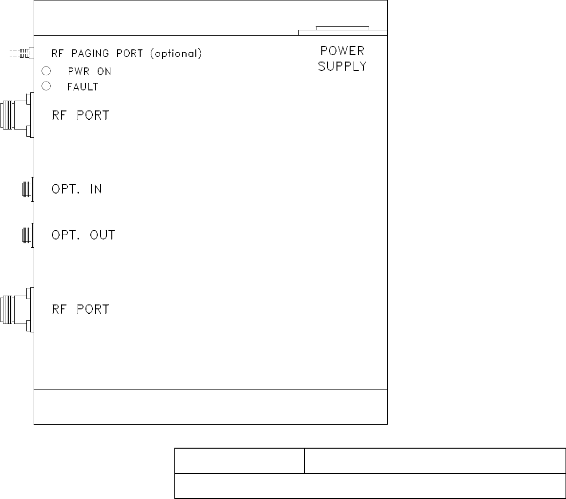
TABLE 3 TFA ALL DUALBAND VERSIONS
REMOTE RF OPTICAL TRANSCEIVER 2 RF-PORTS