Andrew Wireless Innovations Group BCEL-400 RF Signal Booster User Manual MN010 04
Andrew Wireless Innovations Group RF Signal Booster MN010 04
Contents
- 1. Manual 1 0f 2
- 2. Manual 2 0f 2
Manual 1 0f 2

SYSTEM INSTALLATION MANUAL
Rel. 4

BRITECELL System Manual MN010-04 June 2003 Page 2 of 78
The company has a policy of continuous product development and improvement and we therefore
reserve the right to vary any information quoted without prior notice.
Copyright Tekmar Sistemi s.r.l.
This document contains information, which is the property of Tekmar Sistemi S.r.l.
The contents are confidential, any reproduction of all or part of this publication, without
the written consent by Tekmar Sistemi s.r.l is forbidden.
This publication is issued to provide outline information and is not deemed to form any part
of any offer and contract. The company has a policy of continuous product development
and improvement and we therefore reserve the right to vary any information quoted
without prior notice.
Britecell is designed & manufactured by

BRITECELL System Manual MN010-04 June 2003 Page 3 of 78
The company has a policy of continuous product development and improvement and we therefore
reserve the right to vary any information quoted without prior notice.
1. INDEX
1. INDEX .......................................................................................................3
GENERAL INFORMATION ...................................................................................6
2. HOW TO READ THIS MANUAL.....................................................................7
3. INSTALLATION & SAFETY REQUIREMENTS..................................................8
3.1. Environmental conditions: .................................................................8
3.2. Installation site features....................................................................8
3.3. Power connection .............................................................................9
3.4. Safety and precautions during the installation..................................... 9
3.5. Safety and precautions for lasers .......................................................9
3.6. Warning Labels............................................................................... 10
BRITECELL SYSTEM......................................................................................... 11
4. SYSTEM DESCRIPTION............................................................................. 12
4.1. Services ......................................................................................... 13
4.2. Block diagram................................................................................. 13
4.3. Functional description ..................................................................... 14
5. EQUIPMENT DESCRIPTION....................................................................... 15
5.1. Britecell™ subracks ........................................................................ 15
5.2. Subrack modules ............................................................................ 15
5.3. Remote equipment ......................................................................... 16
TFL local unit .................................................................................................. 17
6. Introduction............................................................................................. 18
7. Part description ........................................................................................ 18
8. Warnings ................................................................................................. 19
8.1. Connectors care and cleaning .......................................................... 19
8.2. Laser caution.................................................................................. 19
9. Functional description............................................................................... 20
9.1. Block diagram................................................................................. 20
9.2. Down link operations ...................................................................... 20
9.3. Up link operations........................................................................... 21
10. Alarms and settings ................................................................................ 21
11. Installing and cabling.............................................................................. 23
11.1. TPR housing................................................................................ 23
11.2. Power supply .............................................................................. 23
11.3. RF inputs .................................................................................... 23
11.4. Optical connections ..................................................................... 24
12. Start-up ................................................................................................. 24
13. Troubleshooting ..................................................................................... 25
TFA remote unit .............................................................................................. 26
14. Introduction ........................................................................................... 27
15. Part description ...................................................................................... 27
16. Warnings ............................................................................................... 28
16.1. Connector care and cleaning ........................................................ 28
16.2. Laser caution .............................................................................. 28
17. Functional description ............................................................................. 29
17.1. Block diagram ............................................................................. 29
17.2. Down link operation..................................................................... 29
17.3. Up link operations. ...................................................................... 30
18. Alarms and settings ................................................................................ 30
18.1. LED alarms ................................................................................. 30
18.2. External alarms ........................................................................... 30
18.3. Setting uplink gain (PGR) ............................................................. 31
19. Installing and cabling.............................................................................. 32

BRITECELL System Manual MN010-04 June 2003 Page 4 of 78
The company has a policy of continuous product development and improvement and we therefore
reserve the right to vary any information quoted without prior notice.
19.1. Location...................................................................................... 32
19.2. Power supply and grounding ........................................................ 32
19.3. RF combined ports ...................................................................... 33
19.4. Optical fibres connection.............................................................. 33
20. Start-up ................................................................................................. 33
21. Troubleshooting ..................................................................................... 34
TPR 19" subrack.............................................................................................. 35
22. Introduction ........................................................................................... 36
23. Part description ...................................................................................... 36
24. Warnings ............................................................................................... 36
25. Functional description ............................................................................. 37
25.1. Block diagram ............................................................................. 37
26. Alarms ................................................................................................... 37
27. Installation and cabling ........................................................................... 40
27.1. Location...................................................................................... 40
27.2. Power supply .............................................................................. 40
28. Start up ................................................................................................. 42
29. Troubleshooting ..................................................................................... 42
TFL-BSI RF attenuator ..................................................................................... 43
30. Introduction ........................................................................................... 44
31. Part description ...................................................................................... 44
32. Warnings ............................................................................................... 44
33. Functional description ............................................................................. 44
33.1. Down link operation..................................................................... 44
33.2. Uplink operation .......................................................................... 45
34. Installation and cabling ........................................................................... 45
34.1. TPR housing................................................................................ 45
35. Calculation of attenuation setting ............................................................ 45
35.1. Downlink..................................................................................... 45
35.2. Uplink ......................................................................................... 45
TLC RF combiner - splitter................................................................................ 46
36. Introduction ........................................................................................... 47
37. Part description ...................................................................................... 47
38. Functional description ............................................................................. 47
39. Warnings ............................................................................................... 47
40. Installation and cabling ........................................................................... 47
40.1. TPR housing................................................................................ 47
THYB common path RF combiner ..................................................................... 48
41. Introduction ........................................................................................... 49
42. Part description ...................................................................................... 49
43. Functional description ............................................................................. 49
44. Warnings ............................................................................................... 49
45. Installation and cabling ........................................................................... 49
TFB booster .................................................................................................... 50
46. Introduction ........................................................................................... 51
47. Part description ...................................................................................... 51
48. Warnings ............................................................................................... 51
49. Functional description ............................................................................. 51
49.1. Block diagram ............................................................................. 51
49.2. Description.................................................................................. 52
50. Alarms ................................................................................................... 52
51. Installation and cabling ........................................................................... 52
51.1. Location...................................................................................... 52
51.2. Power supply and grounding ........................................................ 53
51.3. RF combined ports ...................................................................... 53
52. Start up ................................................................................................. 53
53. Troubleshooting ..................................................................................... 54

BRITECELL System Manual MN010-04 June 2003 Page 5 of 78
The company has a policy of continuous product development and improvement and we therefore
reserve the right to vary any information quoted without prior notice.
TPA antenna ................................................................................................... 55
54. Introduction ........................................................................................... 56
55. Functional description ............................................................................. 57
56. Installation and cabling ........................................................................... 58
56.1. Location...................................................................................... 58
56.2. Location examples....................................................................... 59
56.3. Wall mount ................................................................................. 59
56.4. Connectivity ................................................................................ 60
57. Troubleshooting & maintenance .............................................................. 60
SYSTEM INSTALLATION................................................................................... 61
58. Installation and cabling ........................................................................... 62
58.1. Local unit and subrack location .................................................... 62
58.2. Remote unit and antennas location............................................... 62
58.3. Fibre-Optic Cables ....................................................................... 62
58.4. Power Supply .............................................................................. 65
59. SYSTEM START-UP ................................................................................. 65
60. MAINTENANCE....................................................................................... 66
60.1. Plug-in cards removal .................................................................. 66
60.2. Optical equipment ....................................................................... 66
OTHER INFORMATION .................................................................................... 67
61. TERMINOLOGY....................................................................................... 68
62. WARRANTY CONDITIONS ....................................................................... 68
63. DECLARATION OF CONFORMITY............................................................. 70
64. TECHNICAL SUPPORT............................................................................. 70
APPENDIX....................................................................................................... 71
65. APPENDIX A - Britecell system design basics ............................................ 72
65.1. Indoor propagation...................................................................... 72
65.2. Fibre-optic transmission ............................................................... 73
65.3. Coverage method ........................................................................ 74
66. APPENDIX B - Britecell input power level setting....................................... 75
66.1. Down link power levels ................................................................ 75
66.2. Down link power levels: remote unit + booster ............................ 76
67. APPENDIX C - Classifying hazardous areas .............................................. 77
68. APPENDIX D - Health and safety warnings ............................................... 78

GENERAL INFORMATION
BRITECELL System Manual MN010-04 June 2003 Page 7 of 78
The company has a policy of continuous product development and improvement and we therefore
reserve the right to vary any information quoted without prior notice.
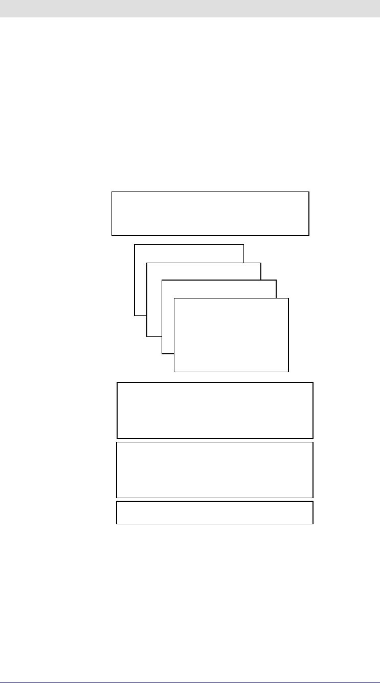
2. HOW TO READ THIS MANUAL
This manual provides equipment specifications, operational descriptions,
application, and installation information as well as a troubleshooting guide. It is
intended to be a comprehensive document used to install and operate a Britecell
system.
The manual consists of many sections.
The first main section includes a global description of the Britecell system, major
equipment warnings, warranty information, customer service and support as well
as troubleshooting guidelines.
Other sections describe specific components, which are used to build or expand a
Britecell system. Each section points out warnings and installation instructions.
GENERAL SECTION:
• general & safety requirements
• s
y
stem descri
p
tion
TFL section
TFA section
Subrack section
…
SYSTEM SECTION
• installation requirements
• start-up
• maintenance
OTHER INFORMATION
• terminology
• warranty & support
• declaration of conformit
y
APPENDIX

BRITECELL System Manual MN010-04 June 2003 Page 8 of 78
The company has a policy of continuous product development and improvement and we therefore
reserve the right to vary any information quoted without prior notice.
3. INSTALLATION & SAFETY REQUIREMENTS
3.1. Environmental conditions:
This equipment is designed to be installed inside buildings.
Operating temperature: +5 to +40°C
Do not install in corrosive atmosphere or in critical environmental conditions such
as hazardous classified areas (for example see appendix C).
3.2. Installation site features
A trained technician should carry out the installation of the donor rack. Since the
system is designed for indoor installation, the rack should be installed in a dry and
suitable location where:
• no explosion risks is present;
• the environment is not classified as a high-risk one in case of fire;
• suspended particles are not to be found in great concentration;
• the environment is not subject to any traffic which could cause crash
damages;
• the site is properly located with respect to the ergonomic positioning of the
working environments;
• the system is placed in a private room, protected against any possible
violation;
• the system must not be exposed to ultra-violet rays;
• the site must be accessible by maintenance personnel;
• the site must be dry, with low humidity;
• the site must guarantee proper space for cables and natural ventilation to the
system;
• 2 meters must be kept from the rack to any heating opening.
The remote units should be mounted in reasonable locations as well:
• do not install inside heating or conditioning;
• do not install inside cable pipeline, fire-prevention site, (fire escape, lift
tunnels, emergency exits, which have to guarantee defined safety standards);
• keep into consideration that the temperature in the upper part of a room is
higher than at 2 meters height. For false ceiling installation, verify that the
environment temperatures do not exceed allowed limits;
• remote unit requires its own power and a connection to the mains can be
needed;
• keep into consideration that the remote unit transmits RF signal and safety
volume must be respected (refer to country regulations for safety volume
magnitude);
• remote units are typically installed next to the ceiling and for safety reasons
they must be properly mounted;
• remote units must be accessible for tests and maintenance.

BRITECELL System Manual MN010-04 June 2003 Page 9 of 78
The company has a policy of continuous product development and improvement and we therefore
reserve the right to vary any information quoted without prior notice.
3.3. Power connection
Power connection has to be carried out following all the necessary precautions:
• it must be properly made according to the due diligence rules (ex.: CEI rules,
IEC rules, etc.);
• in accordance with the rules for safety against direct or indirect contacts;
• in accordance with the rules for safety against the over current (short circuit,
overloading);
• in accordance with the rules for safety against over tension;
• connection is to be carried out by proper and competent staff
3.4. Safety and precautions during the installation
During installation the following means and tools will be needed:
Typical electrician tools:
cross-point screwdriver, scissors, pliers, nippers, drill and bits, screw for fixing
remote units to the wall.
Typical means:
proper ladder, scaffolding or air platform for ceiling installation of remote units.
9
N.B: cautions should be used when installing at a height upper than 2 meters.
Personnel who are installing this equipment should be informed about the
possible risks and safety measures when elevated.
3.5. Safety and precautions for lasers
The laser used in Britecell contains an optical transmitter, which has a power level
that is not dangerous to a person's health. However it is classified as class III B
(norm EN60825) equipment. It is nevertheless prudent in the installation phase to
observe the following rules:
9
Never look directly at the internal optic connector exit of the transmitter
apparatus when it is switched on. The wavelength of the laser is not visible to
the human eye, which means that long-term damage will not immediately be
known.
9
When working with the optical connectors, check at each end that both
transmitting lasers are switched off.
BRITECELL System Manual MN010-04 June 2003 Page 10 of 78
The company has a policy of continuous product development and improvement and we therefore
reserve the right to vary any information quoted without prior notice.
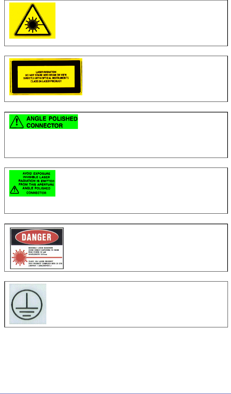
3.6. Warning Labels
Caution! - invisible laser radiation from
this aperture
Caution! - Laser radiation. Do not stare
into the beam or view directly with optical
instruments –
CLASS 3A laser product
Caution! - angled polished connector
Caution! - invisible laser radiation from
this aperture –
angle polished connectors
Caution! - possible invisible laser radiation,
max. power 30mW,
wavelength 1300nm,
laser product CLASS III B
GROUND - Use this terminal for a safety
ground connection of the equipment.

BRITECELL SYSTEM

BRITECELL System Manual MN010-04 June 2003 Page 12 of 78
The company has a policy of continuous product development and improvement and we therefore
reserve the right to vary any information quoted without prior notice.
4. SYSTEM DESCRIPTION
Britecell is a low power distribution system designed to provide indoor coverage for
mobile communication networks.
.The whole system is based on the fiberoptic transmission of multiple RF carriers
from an optical donor unit interfacing to the BTSs (TFL) and an optical remote unit
located in remote sites (TFA) near an antenna.
The transmission of the uplink and downlink RF signals is attained by using bi-
directional fiberoptic links. Furthermore it is possible to reach and feed multiple
remote antennas by distributing a number of fiberoptic links in a star configuration.
The system has been designed to make use of the concept of “low power
distributed antenna system” (DAS). The premise of the DAS system is to achieve
good link quality through the use of many lower power radiating points (fed by
TFAs).
The advantage of this system is lower costs and higher reliability. This is possible
because high power amplifiers are both costly and less reliable than low power
devises.
Britecell is very simply and including a built-in AGC. As such it requires a minimum
design, installation and set-up effort, in contrast with a comparable active cable
systems, which require considerable uplink and downlink design and optimisation.
The system.
A rack complete with 6 donor units (TFLs), a remote unit (TFA) and two antennas
BRITECELL System Manual MN010-04 June 2003 Page 13 of 78
The company has a policy of continuous product development and improvement and we therefore
reserve the right to vary any information quoted without prior notice.
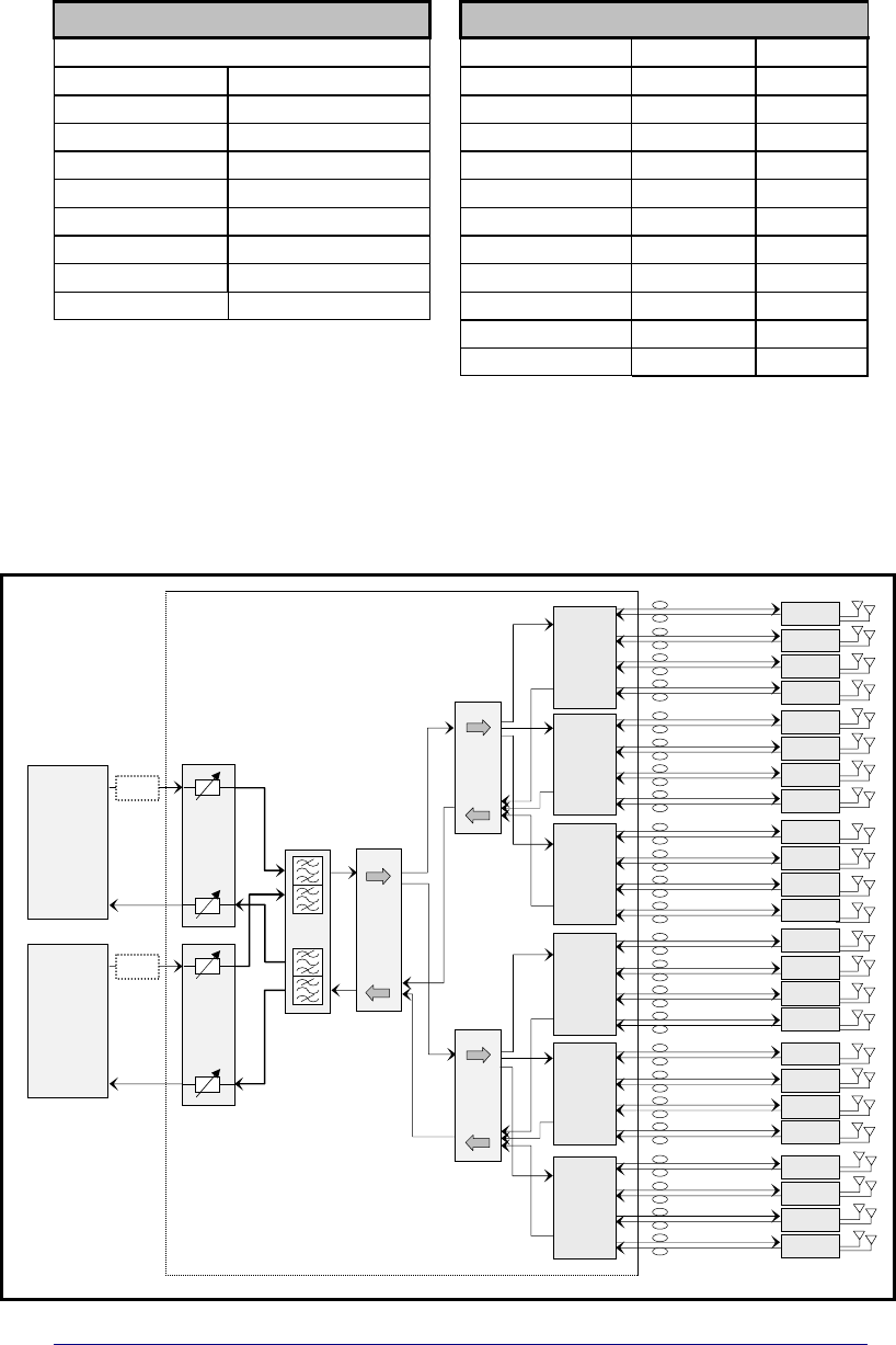
4.1. Services
The Britecell system can operate with single band or dual-band. The following is a
list of possible standards with related frequencies:
FREQUENCY OPTIONS BANDWIDTH [MHz]
uplink downlink
UHF GSM900+GSM1800 UHF 406:512 406:512
VHF paging GSM900+PCS VHF paging --- 270:290
TRUNKING RADIO AMPS+PCS
TRUNKING RADIO 805:825 850:870
AMPS AMPS+DCS PDC800 810:830 940:960
GSM900 TRUNKING+PCS AMPS 824:849 869:894
PDC1500 E-GSM+GSM1800 E-GSM 880:915 925:960
GSM1800 E-GSM+PCS GSM 890:915 935:960
PCS UMTS (UTRA FDD) PDC1500 1429:1453 1477:1501
E-GSM GSM1800 1710:1785 1805:1880
PCS 1850:1910 1930:1990
UMTS 1920:1980 2110:2170
Tab. 1 - services
4.2. Block diagram
This is a basic system configuration. The overall system design and coverage
project may need different architectures, and different ancillary configurations.
Fig. 1
TPR 912
Max 1.5 Km O
p
t. Fiber
TFA
TFA
TFA
TFA
Card 1
TFL
Card 3
TFL
Card 2
TFL
TLC
2503
-6 dB
-6 dB
TLC
2503
-6 dB
-6 dB
Card 4
TFL
Card 5
TFL
Card 6
TFL
TLC
2502
-4 dB
-4 dB
TLC
2501
TFL
BSI
UL-variable
Attenuator
DL-variable
Attenuator
TFL
BSI
UL-variable
Attenuator
DL-variable
Attenuator
TX
Low
Band
BTS
RX
A
TX
High
Band
BTS
RX
A
TFA
TFA
TFA
TFA
TFA
TFA
TFA
TFA
TFA
TFA
TFA
TFA
TFA
TFA
TFA
TFA
TFA
TFA
TFA
TFA
Fig. 2 - Block diagram

BRITECELL System Manual MN010-04 June 2003 Page 14 of 78
The company has a policy of continuous product development and improvement and we therefore
reserve the right to vary any information quoted without prior notice.
4.3. Functional description
The basic system blocks are the fiber donor unit TFL (Local Unit) and the fiber
remote unit TFA (Remote Unit).
They are connected in both directions (uplink and downlink) through single mode
optical fibre.
The system has a built-in Automatic Gain Control (AGC), which automatically
adjust the up link and down link gain in order to compensate for optical link loss1.
This allows the downlink transmit power and the up link sensitivity to be virtually
independent on fibre length and on the number of splices or optical connectors
present along the fibre link.
Each Local unit can support and constantly monitor up to 4 remote units.
Moreover up to 6 central units can be housed, together with power supply, in the
same subrack 19”.
The TFA feeds up to two coverage antennas. In this way it is possible to set up a
network of 24 transceivers and up to 48 coverage antennae (see Fig.2).
The connection between the BTS and Britecell system can either be direct or,
through a repeater.
In Fig. 1, a typical direct connection to BTS is showed for a dual band system. The
building blocks of the combining network are:
• two/three way combiners and splitters (TLC2502/3);
• cross-band couplers (TLC2501);
• variable attenuators (TFL-BSI).
The combining network has to be carefully designed in order to optimise the
connection to the BTS and the system performances.
1 provided that the specified limits are not exceeded (please refer to datasheets)
BRITECELL System Manual MN010-04 June 2003 Page 15 of 78
The company has a policy of continuous product development and improvement and we therefore
reserve the right to vary any information quoted without prior notice.
5. EQUIPMENT DESCRIPTION
Britecell is a modular system. Many options and accessories are available,
depending on the desired coverage area. The following is a list of main
accessories, suitable for most applications.
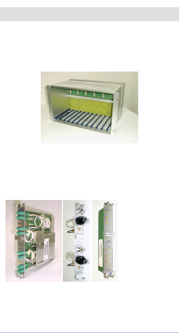
5.1. Britecell™ subracks
The Local Units are located inside a 19” 6HE sub-rack. From this rack, power is
supplied for the all fibre donor units (TFL).
Fig. 3 – 19” sub-rack
Subrack can be supplied by a -48V DC or by universal mains (85-264VAC). See
datasheets for further details.
Power switches and fuses are placed on subrack back panel (see TPR section
below).
5.2. Subrack modules
• TFL is the RF to optical converter.
• TFL-BSI is a variable RF attenuator (0-30dB)
• TLC2502 and TLC2503 are RF splitters/combiners
TFL - LOCAL UNIT TFL-BSI TLC2502

BRITECELL System Manual MN010-04 June 2003 Page 16 of 78
The company has a policy of continuous product development and improvement and we therefore
reserve the right to vary any information quoted without prior notice.
5.3. Remote equipment
Fig. 4 - TFA remote unit Fig. 5 - TPAxxx -
remote antenna
Fig. 6 - TFB - RF booster
TFA is the optical to RF converter.
TPA is the suggested indoor antenna family.
TFB is the RF booster if needed to extend the coverage area.
TFA can feed up to two antennas while TFB can be connected to one antenna.
Detailed descriptions of these components are available in the sections below.

TFL local unit
BRITECELL System Manual MN010-04 June 2003 Page 18 of 78
The company has a policy of continuous product development and improvement and we therefore
reserve the right to vary any information quoted without prior notice.
6. Introduction
This section describes the TFL (Local Unit). The TFL is the part of Britecell system
that provides E/O downlink conversion and O/E uplink conversion of RF signal.
The TFL is connected to remote TFA by means of two optical fibres.
The system forms a star configuration. One fibre is dedicated to the transmission
of the downlink signals received from BTS and re-transmitted to the mobile. The
other fibre supports the transmission of up-link signals, received from mobile
through the TFA remote units and destine for the BTS.
The TFL cards are 6HE plug-in modules and are contained in a standard 19”
subrack (TPR family).
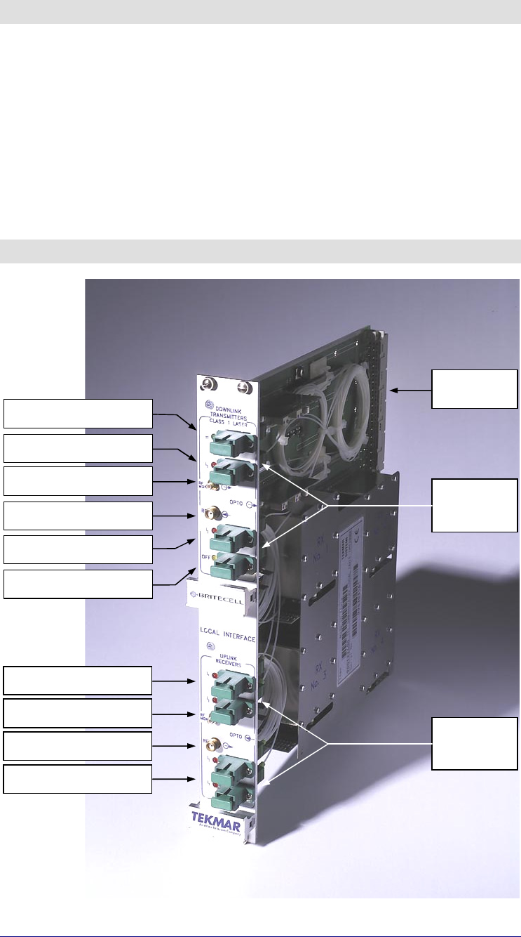
7. Part description
Fig. 7 – TFL Local Unit part description
Power Supply led (green)
DL Laser Alarm (red)
DL RF Test Port (SMB-m)
DL RF Input (SMA-f)
Dummy (used in other application)
Uplink
Optical
Connectors
UL Alarm leds (red)
UL RF Test Port (SMB-m)
UL RF Output (SMA-f)
Backplane
Connector
Downlink
Optical
Connectors
Laser off led (yellow)
UL Alarm leds (red)

BRITECELL System Manual MN010-04 June 2003 Page 19 of 78
The company has a policy of continuous product development and improvement and we therefore
reserve the right to vary any information quoted without prior notice.
8. Warnings
9
CAUTION! do not remove or insert any module into TPR subrack, without prior
switching power supply off.
8.1. Connectors care and cleaning
Optical connectors for single mode fibers are designed for submicron tolerances.
Such a connector has an optical section of only 9 µm diameter. The rules below
must be carefully followed
9
Do not leave optical connectors open, as they will attract dirt.
9
Do not touch the connector tip. Clean it with a proper tissue before inserting it
into the sleeve.
If a better cleaning is needed, use pure ethyl alcohol. Sleeves may be cleaned by
injecting pure gas under pressure.
9
Do not attempt to insert connectors mechanically incompatible. This will result
in severe damage.
The optical connector is a high precision device. It must be handled with care, to
avoid scratches and other mechanical/optical damages that will impair or reduce
the system’s performance.
8.2. Laser caution
The TFL contains semiconductor lasers. Precautions should be taken when
handling, installing or servicing this equipment.
Invisible laser radiation may be emitted from the optical transmitter orifice at the
TFL local interface:
9
Do not stare into the beam or use optical instruments with powered
equipment.
BRITECELL System Manual MN010-04 June 2003 Page 20 of 78
The company has a policy of continuous product development and improvement and we therefore
reserve the right to vary any information quoted without prior notice.
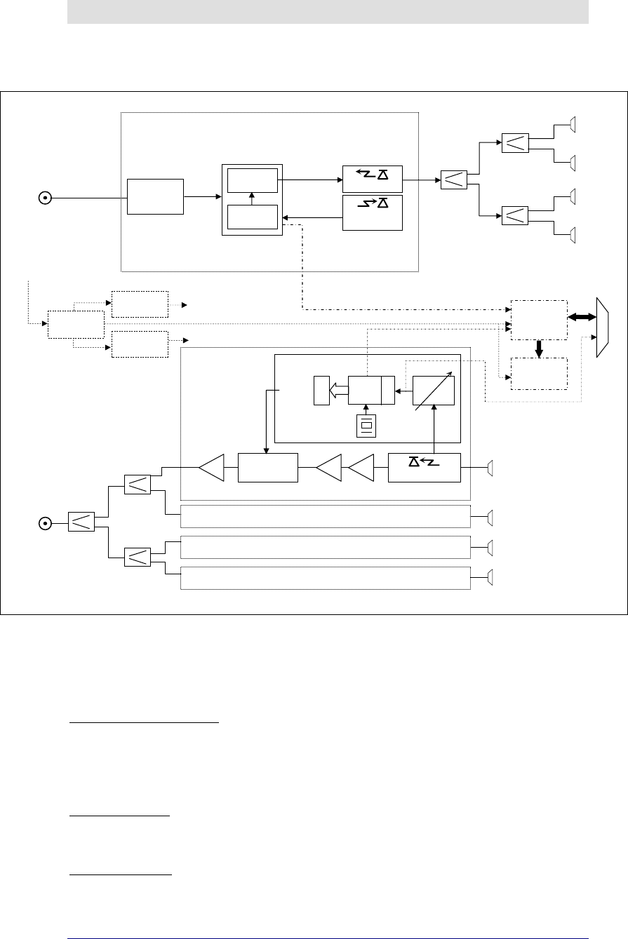
9. Functional description
9.1. Block diagram
Fig. 8 - block diagram
9.2. Down link operations
In down link the TFL fulfils the following operations:
Power level adjustment:
if the RF signal coming from the BTS has a power level which is not
adequate to TFL’s characteristics, an external adjustment is required. It
consists in an attenuation when BTS is connected through a coupler or
through repeater (please refer to TFL-BSI).
E/O Conversion:
RF signal modulates the intensity of an optical carrier through an electro-
optic device (laser). One laser is present on each TFL card.
Optical Splitting:
modulated optical carrier is split into 4 ways so that it may be transmitted
on a maximum of 4 optical links.
RF IN
50 Ω
CURRENT
GENERATOR
NOISE
GENERATOR
Laser bias
Opt. power
monitor
IMPEDANCE
MATCHING
NETWORK
VOPT
2-ways
combiner
+8V
VOLTAGE
REGULATOR
LASER module
MONITOR
PHOTODET.
LASER DIODE
STATUS MONITOR
LEDS AND ALARM
LEDS
ALARMS AND
COMMAD
CONNECTOR
VOLTAGE
REGULATOR
2-ways
combiner
VOLTAGE
CONTROLLED
ATTENUATOR PHOTODETECTOR
LNA AMP AMP
TFLMICRO module
VARIABLE
GAIN AMP.
4 MHz
D
A
C
A
D
C
µPROC.
2-ways
combiner
RF OUT
50 Ω
Optical
connectors
Pwr supply is
on
Pwr fault
TX
Low RX
opt.power
2-ways opt.
s
p
litter
Optical
connectors
POWER SUPPLY
U
NIT
+12V
Downlink Transmitter
ALARMS AND
COMMAND SIGNALS
MANAGEMENT
CIRCUITS
Uplink Receiver 1
Uplink Receiver 2
Uplink Receiver 3
Uplink Receiver 4
+5V
AC input from mains
2-ways opt.
s
p
litter
2-ways opt.
s
p
litter

BRITECELL System Manual MN010-04 June 2003 Page 21 of 78
The company has a policy of continuous product development and improvement and we therefore
reserve the right to vary any information quoted without prior notice.
9.3. Up link operations
In uplink, signals pass through a duplexer and are then subjected to the following
operations:
O/E Conversion:
there are 4 O/E conversion devices (or optical receivers) in one TFL (one
for each optical link).
Amplification:
amplification is needed to compensate the optical fibre loss (maintaining a
good signal to noise ratio) so that for each link a constant gain is obtained.
RF Combining:
signals coming from all the remotes are combined into a single RF port.
Power level Adjustment:
TFL output may need a level adjustment so that the RF signals are within
the optimum BTS receiving range (please refer to TFL-BSI).
10. Alarms and settings
Two types of local alarm are available:
Visual alarms:
the front panel of a TFL Local Unit shows the following status for alarm LEDs:
Link LED Colour Meaning (when lit)
= Green Laser is biased
Red Laser optical power under limits
and/or bias is not present.
Downlink
Transmitter
OFF Yellow Laser has shutdown command.
Uplink receivers Red Input optical power is lower
than pre-set.
Tab. 2 -Alarm LEDs
Relay logic alarms detectable on connector:
in the rear of TFL units an alarm interface connector passes information about
summary alarms and specific alarms which can be sent to an OMC (Operating and
Maintenance Centre) via the BTS. In addition the alarms may be monitored from
Britecell’s own OMC (please refer to TPR).
Settings:
No adjustments are required at local interface module.
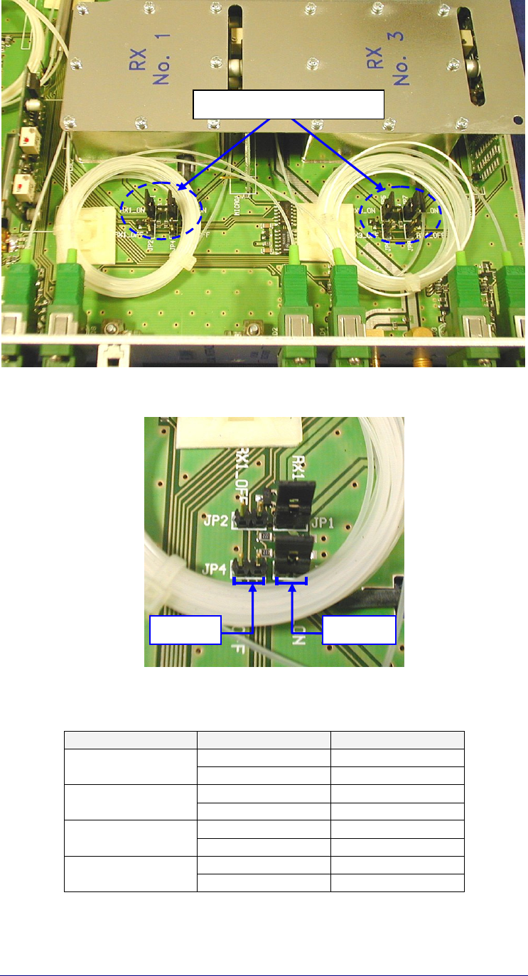
Four optical receivers are present at each TFL.
Unused receivers may cause uplink alarms if enabled. In order to avoid UL alarms
unused receivers must be turned off. This can be done simply changing jumper
position as shown on Fig. 9 and Fig. 10 .
Tab. 3 is a chart of the correct jumper positions.
Each receiver has a number silk screen printed on the metal protection, which
corresponds to the relevant UL optical port on the TFL front panel.
The jumper number and relevant receiver status are printed on TFA main board,
so that the operation results very simple.
BRITECELL System Manual MN010-04 June 2003 Page 22 of 78
The company has a policy of continuous product development and improvement and we therefore
reserve the right to vary any information quoted without prior notice.
Fig. 9- Uplink jumpers
Fig. 10- Uplink jumper positions
Receiver Status Jumper position
ON JP1
RX No.1 OFF JP2
ON JP3
RX No.2 OFF JP4
ON JP5
RX No.3 OFF JP6
ON JP7
RX No.4 OFF JP8
Tab. 3 - Jumper positions
Uplink receiver enabling Jumpers
RX ON RX OFF

BRITECELL System Manual MN010-04 June 2003 Page 23 of 78
The company has a policy of continuous product development and improvement and we therefore
reserve the right to vary any information quoted without prior notice.
11. Installing and cabling
11.1. TPR housing
The TFL modules are contained in a 6 HE sub-rack (TPR family). The local
interfaces cannot be placed next to each other.
The TFL local interface cards may only be fitted in slots 1, 3, 5, 7, 9, and 11 of the
sub-rack.
Fig. 11 - Subrack slots Fig. 12– Dummy plug
If any slots are unused the backplane connectors must be fitted with a dummy
plug (provided) to avoid alarms being generated (see Fig.15).
Installation of Local Interface should be implemented in accordance with standard
rules related to fixed base equipment.
9
WARNING: prior to removing or inserting any modules, make sure that the
power supply is off.
9
WARNING: the TFL cards must be handled with care in order to avoid
damages to electrostatic sensitive devices.
Should a Local Unit need to be removed, first remove the left adjacent module.
The sub-rack housing if correctly installed (see TPR section) provides also the
proper air circulation to the Local Unit.
11.2. Power supply
TFL cards are powered by the proprietary backplane (Sub-rack TPR family), power
consumption is 12W for each TFL.
11.3. RF inputs
The RF combining and interface section, if properly designed, provides the right
power levels to the TFL.
9
WARNING: Do not exceed the maximum RF level allowed for downlink input
(see TFL datasheets). Please refer to the system design for variable attenuator
settings (see system start-up section)
BRITECELL System Manual MN010-04 June 2003 Page 24 of 78
The company has a policy of continuous product development and improvement and we therefore
reserve the right to vary any information quoted without prior notice.
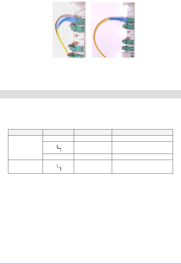
11.4. Optical connections
Optical connectors are designed to have proper alignment and mechanical support.
When inserting an optical connector, take care to handle it smoothly enough so as
not to damage the fibre.
Fasten the fibre cable to the provided seating base by means of the included
wrapper.
Remove the dust cap only immediately before making connections.
9
Do not force or stretch the fibre pigtail with curve radius less than 5 cm. See
Fig. 13 for optimal fibre cabling.
Fig. 13 – Fibre connection
12. Start-up
A preliminary verification of TFL correct operation is:
1. switch-on the TPR subrack
2. verify the following LED status
Link LED Colour Status
= Green ON
Red OFF
Downlink
Transmitter
OFF Yellow OFF
Uplink
receivers
Red
Depending upon TFA status,
always off if receiver alarm
disabled
For a full functionality test please refer to the system start-up section.
WRONG OPTIMAL

BRITECELL System Manual MN010-04 June 2003 Page 25 of 78
The company has a policy of continuous product development and improvement and we therefore
reserve the right to vary any information quoted without prior notice.
13. Troubleshooting
Correct alarm interpretation is very useful not only during the installation, but also
during maintenance
TFL laser failure:
replace the faulty transmitter by replacing the TFL unit with a new one.
RX alarm only:
first go to the TFL site and check if optical connectors of TFL are properly
cleaned.
If the problem still exists, go to the TFA site (the TFA which yields also
visual RX alarm at TFL). If the TFA shows a visual alarm, clean the
downlink optical connector.
If the TFA is still alarmed, measure the downlink optical power at TFA
input with an optical power meter and verify if it is higher than –5 dBm. If
it is not, the fibre cable (at least as far as the downlink fibre is concerned)
has some problems. If optical power is higher than –5 dBm, replace the
TFA.

TFA remote unit
BRITECELL System Manual MN010-04 June 2003 Page 27 of 78
The company has a policy of continuous product development and improvement and we therefore
reserve the right to vary any information quoted without prior notice.
14. Introduction
This section describes the TFA (Remote Unit).
The TFA is part of the Britecell system and provides O/E downlink conversion and
E/O uplink conversion.
The TFA is connected to passive antennas, which transmit and receive from and to
the mobiles.
Each TFA is connected to a TFL through two optical fibres.
This forms a star configuration. One fibre is dedicated to the reception of the
downlink signals that the TFA receives from TFL, and re-transmits to mobile
stations. The other fibre supports the transmission of uplink signals, which each
TFA gathers from the mobiles operating in its coverage area, to the TFL.
TFA can feed antennas through two external RF ports, except UMTS TFA where a
single RF TRx port is provided.
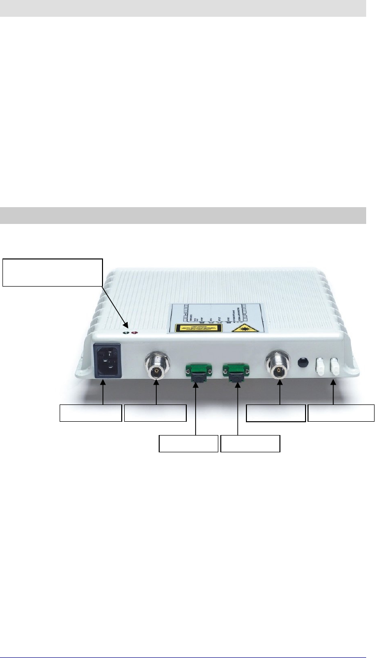
15. Part description
Fig. 14 – TFA Remote Unit part description
Power su
pp
l
y
RF TRx
p
ort
DL o
p
t.
p
ort UL o
p
t.
p
ort
RX TRx
p
ort External alarm
Green LED = power on
Red LED = alarm

BRITECELL System Manual MN010-04 June 2003 Page 28 of 78
The company has a policy of continuous product development and improvement and we therefore
reserve the right to vary any information quoted without prior notice.
16. Warnings
16.1. Connector care and cleaning
9
Do not leave connectors open. Unused optical connectors must always be
covered with their caps.
9
Do not touch the connector tip. Clean it with proper tissue before inserting
them into the sleeve.
If better cleaning is needed, use pure ethyl alcohol. Sleeves may be cleaned by
injecting pure gas under pressure.
9
Do not attempt to insert connectors mechanically incompatible. This will result
in severe damage.
The optical connector is a high precision device. It must be handled with care to
avoid scratches and other mechanical/optical damages that will impair or reduce
the system performance.
16.2. Laser caution
The TFA contains semiconductor lasers. Precautions should be taken when
handling, installing or servicing this equipment.
Invisible laser radiation may be emitted from the optical transmitter connector of
the TFA interface:
9
Do not stare into the beam or use optical instruments with the equipment
powered on.
BRITECELL System Manual MN010-04 June 2003 Page 29 of 78
The company has a policy of continuous product development and improvement and we therefore
reserve the right to vary any information quoted without prior notice.
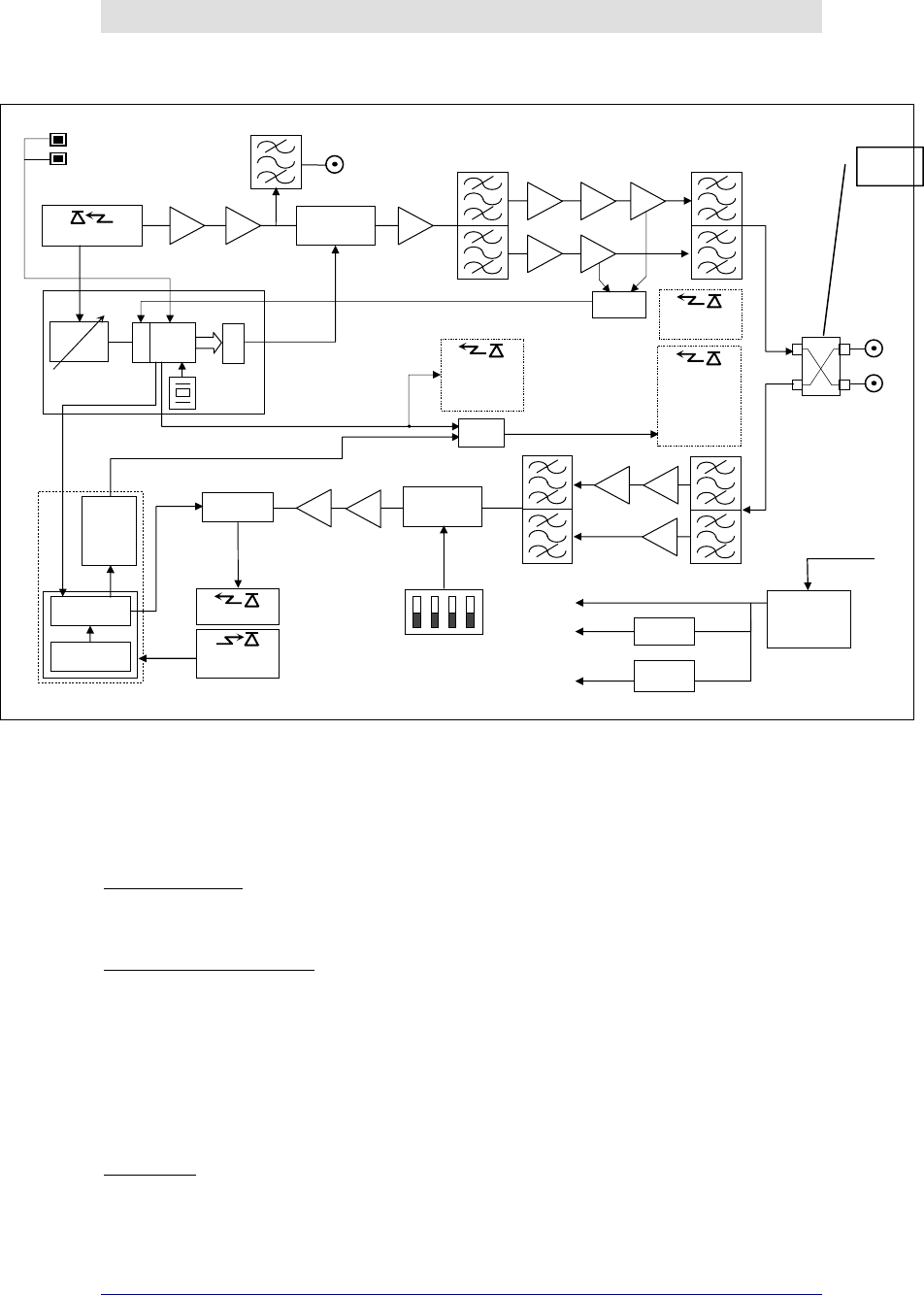
17. Functional description
17.1. Block diagram
Fig. 15 – TFA block diagram
Note 1: not present in UHF TDD version
17.2. Down link operation
In the downlink the TFA fulfils the following operations:
O/E Conversion:
the optical signal is demodulated through an opto-electronic device (p-i-n
photodiode).
Amplification & Filtering:
amplification is required to boost the downlink signal after is converted
from light back to RF. Maintaining a good signal-to-noise ratio is critical for
this operation; part of the amplification process automatically takes into
account the variable loss introduced by the optical fibre.
A clean-up filter is used after the amplification process to limit transmission
to the downlink band and to reduce spurious emissions in the uplink band
where they would interfere with the signal coming from the mobile.
Duplexing:
the RF signal enters a duplexer which combines downlink and uplink on a
single port which is then split and goes to two separate antenna ports.
PHOTODETECTOR LNA AMP
Paging RF SMA
connector 50 Ω
VOLTAGE
CONTROLLED
ATTENUATOR AMP
AMP
AMP
AMP
AMP
AMP
VARIABLE
GAIN AMP.
D
A
C
A
D
C
µPROC.
4 MHz
Diff. AMP
NOISE
GENERATOR
LASER module
MONITOR
PHOTODET.
LASER DIODE
VOLTAGE
CONTROLLED
ATTENUATOR
AMP
AMP
MATCHING
NETWORK
UL ATTENUATOR CONTROL
SWITCHES
attenuator
control
voltage
DL final amplifier stage
current monitor
LNA
AMP LNA
Green LED:
power on
Red LED: UL
final amplifier
stage current
out of allowed
range or low
o
p
tical
p
ower
RF N
50 Ω
RF N
50 Ω
POWER SUPPLY
UNIT
AC input from mains
DC/DC
converter
Voltage
Regulator
RX optical power monitor
Attenuator
control voltage
DL final amplifier stage out
of allowed range
Threshold
circuit
with
adjustable
threshold
level.
Low RX optical
power
CURRENT
GENERATOR
OR
circuit
LASER control
module
+12 V
-8 V
+5 V
Internal LED: DL
final amplifier
stage out of
allowed ran
g
e
External Booster alarms
(note1)

BRITECELL System Manual MN010-04 June 2003 Page 30 of 78
The company has a policy of continuous product development and improvement and we therefore
reserve the right to vary any information quoted without prior notice.
17.3. Up link operations.
In the uplink the TFA performs the following functions:
Filtering & Amplification:
a filter delimits the uplink band and a low noise amplifier increases the
signal level to minimise the noise figure of the link.
E/O Conversion:
the RF signal coming from the antennas modulates the intensity of an
optical carrier through a laser.
18. Alarms and settings
18.1. LED alarms
For TFA units only visual alarms are provided. Two LEDs represent them:
LED Colour Meaning (when lit)
LD1 Red No optical power at DL input and/or
amplifier failure
LD2 Green Power supply is on
Tab. 4 – TFA Alarm LEDs
NOTE:
the uplink laser is on only if downlink optical signal is present and
no failure occurs in the TFA; in case of any failure, the uplink laser is
switched off.
It is useful to note that as a downlink failure will be reported to both TFL a TFA, it
is possible to determine a fibre or TFA failure from either the TFA or TFL.
This information can be used in conjunction to others for troubleshooting (see
par.21).
18.2. External alarms
TFA is provided with two external alarm contacts.
These contacts are open under non-alarm condition (normally open).
Fig. 16 - External alarms (dry contacts)
Alarm when closed
BRITECELL System Manual MN010-04 June 2003 Page 31 of 78
The company has a policy of continuous product development and improvement and we therefore
reserve the right to vary any information quoted without prior notice.
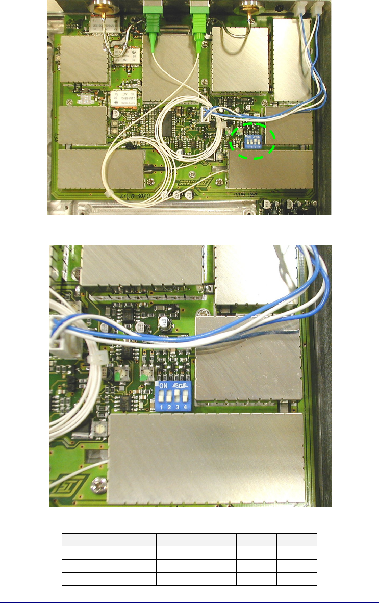
18.3. Setting uplink gain (PGR)
To optimise system performances related to “blocking level” (refer to system
design for further details), TFA units shall include an RF uplink attenuator to adjust
the uplink gain (Pre-settable Gain Reduction – PGR).
Up link gain setting can be easily executed removing the rear lid (see Fig. 17) and
setting SW1 bits (see Fig. 18) according to Tab. 5.
Fig. 17 – TFA PGR dip- switches
Fig. 18 – Dip-switches settings
Gain Reduction bit 1 bit 2 bit 3 bit 4
0 dB OFF OFF ON OFF
5 dB OFF ON OFF OFF
10 dB ON OFF OFF OFF
Tab. 5 - Uplink gain reduction settings
BRITECELL System Manual MN010-04 June 2003 Page 32 of 78
The company has a policy of continuous product development and improvement and we therefore
reserve the right to vary any information quoted without prior notice.
19. Installing and cabling
19.1. Location
TFA units shall be installed as close as possible to the radiating antennas, so as to
minimise coaxial cable length and reduce downlink power loss and uplink noise
figure.
However, the units should be installed no closer than 2.5 m to the closest mobiles
approach to avoid blocking. If remote units need to be installed very close to
where mobiles are, the internal variable attenuator should be used.
The TFA is intended to be installed on walls, false ceilings or other flat surfaces. A
mounting bracket is available for easy mounting.
Proper installation of the TFA is required for optimal performance. Take care to
install the TFAs "warm side out" as indicated in Fig. 14 The positioning of the unit
and the cables is important so as to avoid accidental damage.
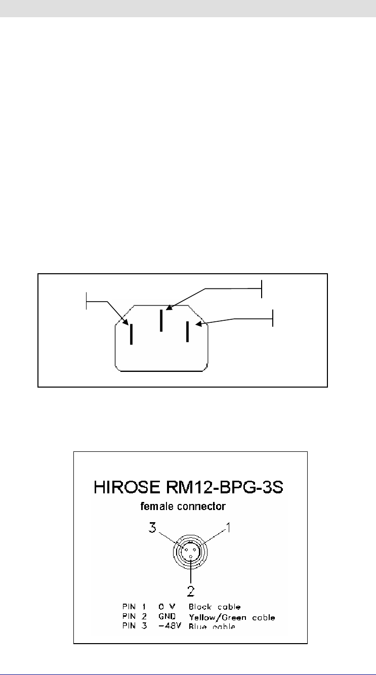
19.2. Power supply and grounding
19.2.1. Universal mains (85-264VAC, 50/60Hz)
Fig. 19 -Mains connector
19.2.2. DC negative supply –72 to –36 VDC.
Fig. 20 - VDC connector
mains
mains
GROUND
DC connector and part number:
BRITECELL System Manual MN010-04 June 2003 Page 33 of 78
The company has a policy of continuous product development and improvement and we therefore
reserve the right to vary any information quoted without prior notice.
19.3. RF combined ports
These ports should be directly connected to the radiating antennas through RF
jumper cables.
Unused RF output ports must be terminated with a dummy 50Ω load. Optional
boosters (TFB family) also can be connected to one or both of the combined ports
for additional RF downlink power.
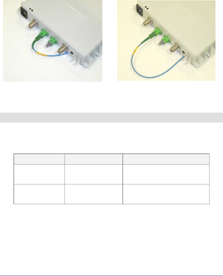
19.4. Optical fibres connection
Optical connectors need to have proper alignment and mechanical support. When
inserting an optical connector, take care to handle it smoothly enough so as not to
damage the fibre. Remove the dust cap only immediately before making
connections.
9
Do not force or stretch the fibre pigtail with curve radius less than 5 cm. See
Fig. 21 for optimal fibre cabling.
WRONG OPTIMAL
Fig. 21 - Fibre connection
20. Start-up
To perform a preliminary verification of the TFA:
• power-up the TPA;
• verify the following LED status:
LED Colour Status
LD1 Red
OFF if optical received power above
lower required limit and internal
operations ok
LD2 Green ON
For a full functionality test please refer to the system start-up section.

BRITECELL System Manual MN010-04 June 2003 Page 34 of 78
The company has a policy of continuous product development and improvement and we therefore
reserve the right to vary any information quoted without prior notice.
21. Troubleshooting
If an alarm LED is active, check the environmental conditions (operating
temperature, supply range, etc.).
If an alarm persists, it is essential to give a correct alarm interpretation is to solve
the problem.
The uplink laser is switched on only if downlink optical power is present. In case of
any failure, the laser is switched off. By doing this, the unit sends information
about its operating status to the TFL.
If the TFA is alarmed, clean the downlink optical connector.
If the TFA is still alarmed, measure the downlink optical power at TFA input with
an optical power meter and verify if it is higher than –5 dBm. If it is not, the fibre
(at least as far as the down link fibre is concerned) has some problems. If optical
power is higher than -5 dBm, replace the TFA.

TPR 19" subrack