Andrew Wireless Innovations Group BCEL-400 RF Signal Booster User Manual MN010 04
Andrew Wireless Innovations Group RF Signal Booster MN010 04
UserManual.wiki
>
Andrew Wireless Innovations Group
>
BCEL-400 User Manual
>
Manual 1 0f 2
Contents
1.
Manual 1 0f 2
2.
Manual 2 0f 2
Manual 1 0f 2
Navigation menu
Upload a User Manual
Namespaces
Wiki Guide
HTML
PDF
Info
Views
User Manual
Discussion / Help
Navigation

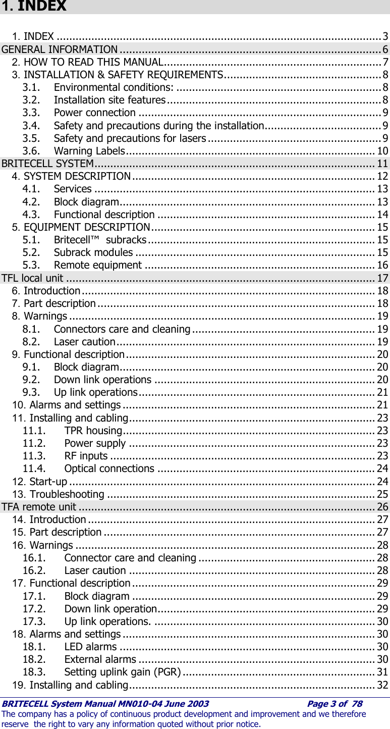

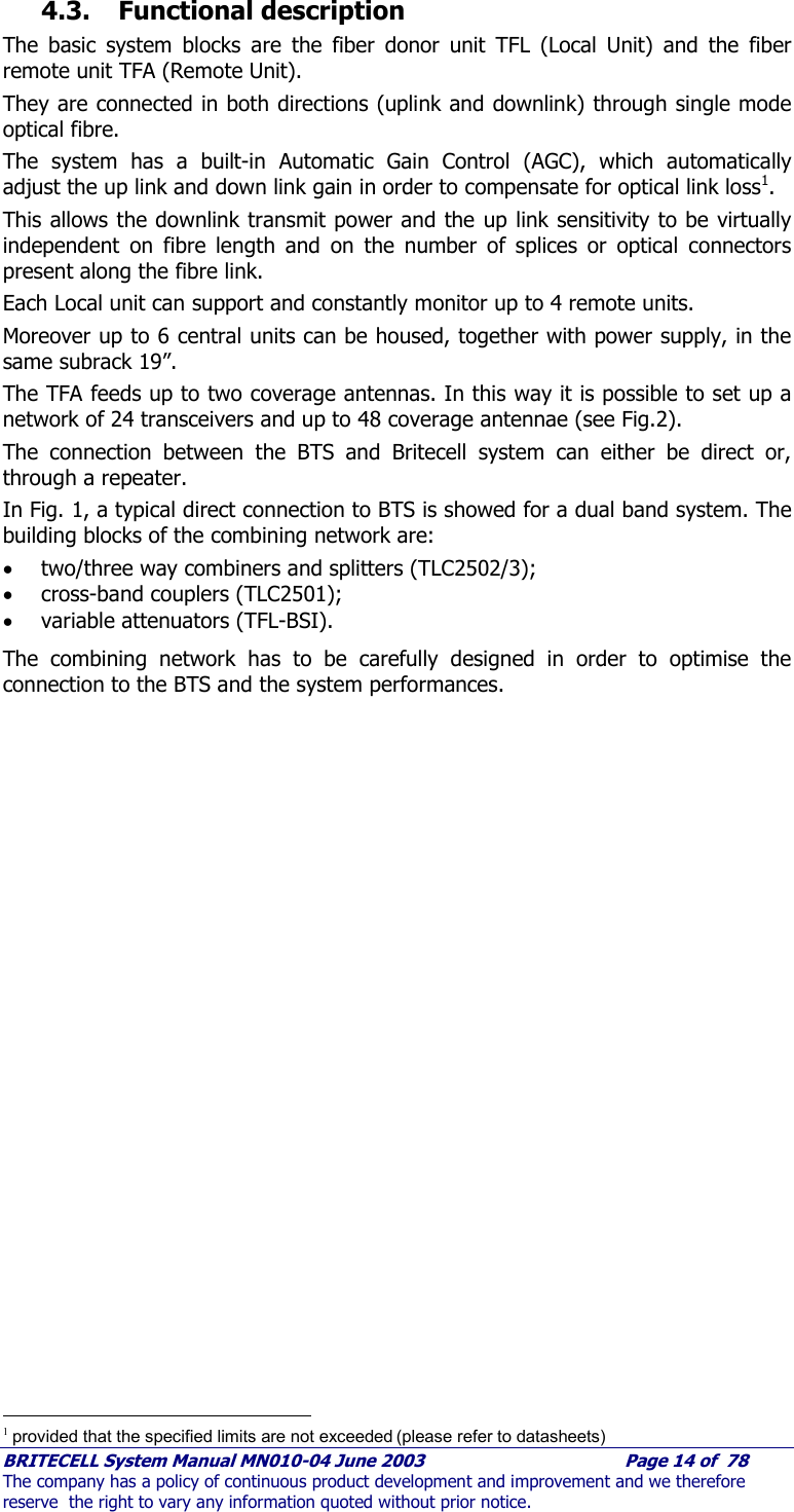
![BRITECELL System Manual MN010-04 June 2003 Page 13 of 78 The company has a policy of continuous product development and improvement and we therefore reserve the right to vary any information quoted without prior notice. 4.1. Services The Britecell system can operate with single band or dual-band. The following is a list of possible standards with related frequencies: FREQUENCY OPTIONS BANDWIDTH [MHz] uplink downlink UHF GSM900+GSM1800 UHF 406:512 406:512 VHF paging GSM900+PCS VHF paging --- 270:290 TRUNKING RADIO AMPS+PCS TRUNKING RADIO 805:825 850:870 AMPS AMPS+DCS PDC800 810:830 940:960 GSM900 TRUNKING+PCS AMPS 824:849 869:894 PDC1500 E-GSM+GSM1800 E-GSM 880:915 925:960 GSM1800 E-GSM+PCS GSM 890:915 935:960 PCS UMTS (UTRA FDD) PDC1500 1429:1453 1477:1501 E-GSM GSM1800 1710:1785 1805:1880 PCS 1850:1910 1930:1990 UMTS 1920:1980 2110:2170 Tab. 1 - services 4.2. Block diagram This is a basic system configuration. The overall system design and coverage project may need different architectures, and different ancillary configurations. Fig. 1 TPR 912 Max 1.5 Km Opt. Fiber TFA TFATFA TFA Card 1 TFL Card 3 TFL Card 2 TFL TLC 2503 -6 dB -6 dB TLC 2503 -6 dB -6 dB Card 4 TFL Card 5 TFL Card 6 TFL TLC 2502 -4 dB -4 dB TLC 2501 TFL BSI UL-variable Attenuator DL-variable Attenuator TFL BSI UL-variable Attenuator DL-variable Attenuator TX Low Band BTS RX A TX High Band BTS RX ATFA TFATFA TFA TFA TFATFA TFA TFA TFATFA TFA TFA TFATFA TFA TFA TFATFA TFA Fig. 2 - Block diagram](https://usermanual.wiki/Andrew-Wireless-Innovations-Group/BCEL-400.Manual-1-0f-2/User-Guide-354066-Page-13.png)