Andrew Wireless Innovations Group BCEL-400 RF Signal Booster User Manual MN010 04
Andrew Wireless Innovations Group RF Signal Booster MN010 04
UserManual.wiki
>
Andrew Wireless Innovations Group
>
BCEL-400 User Manual
>
Manual 2 0f 2
Contents
1.
Manual 1 0f 2
2.
Manual 2 0f 2
Manual 2 0f 2
Navigation menu
Upload a User Manual
Namespaces
Wiki Guide
HTML
PDF
Info
Views
User Manual
Discussion / Help
Navigation
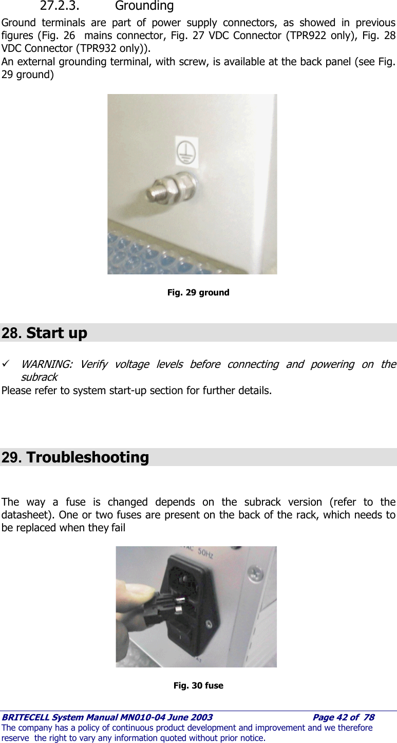
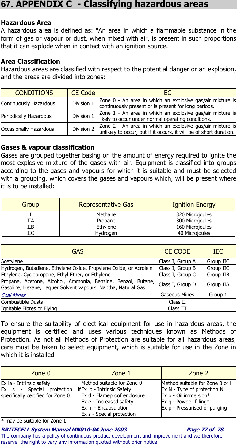
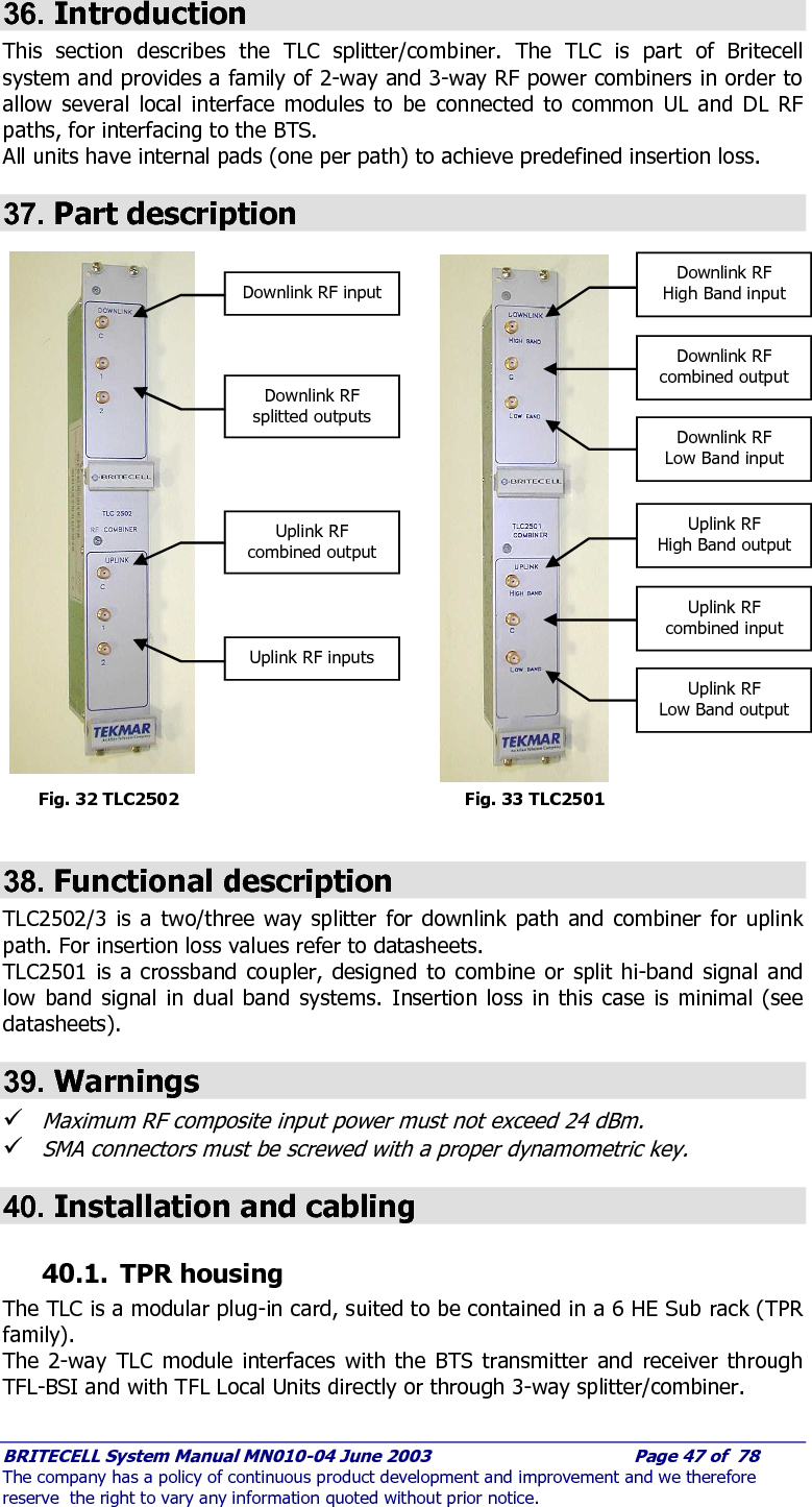
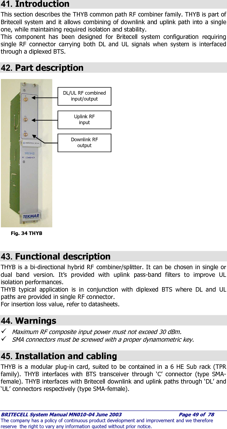
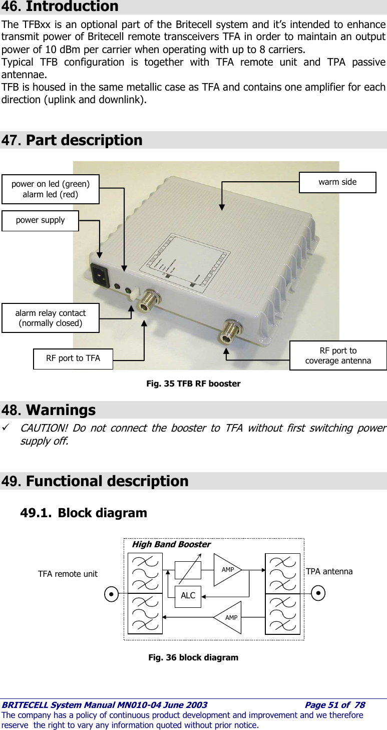
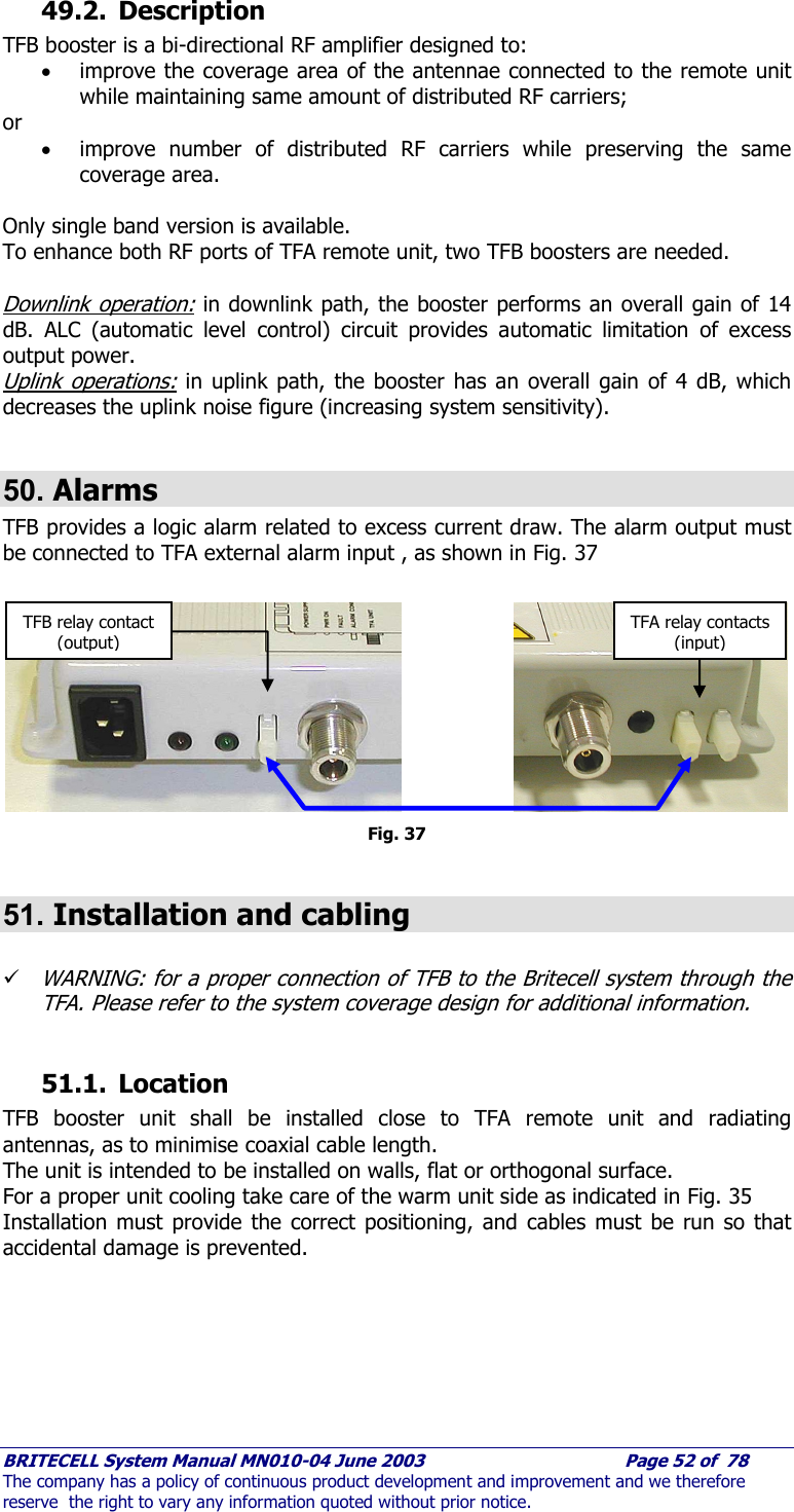
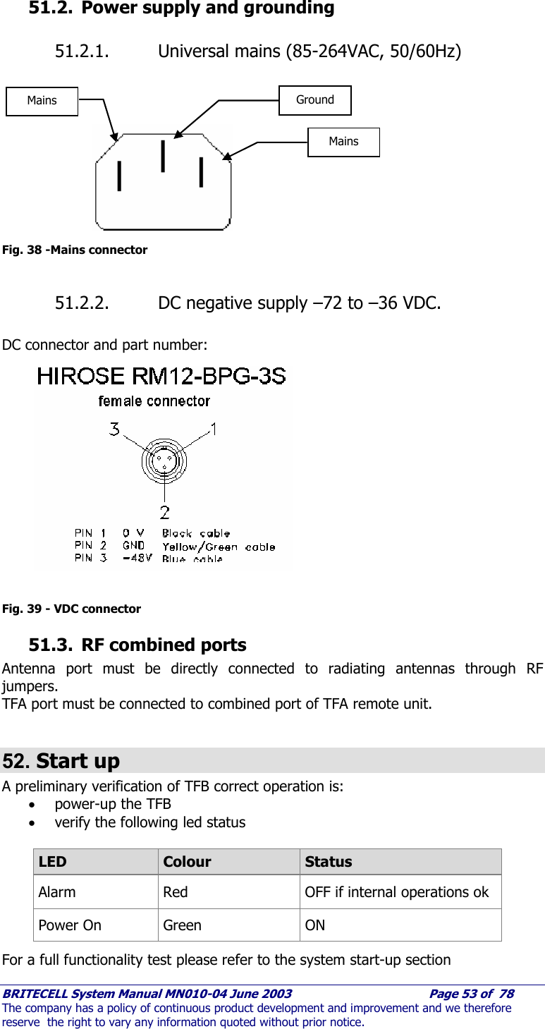
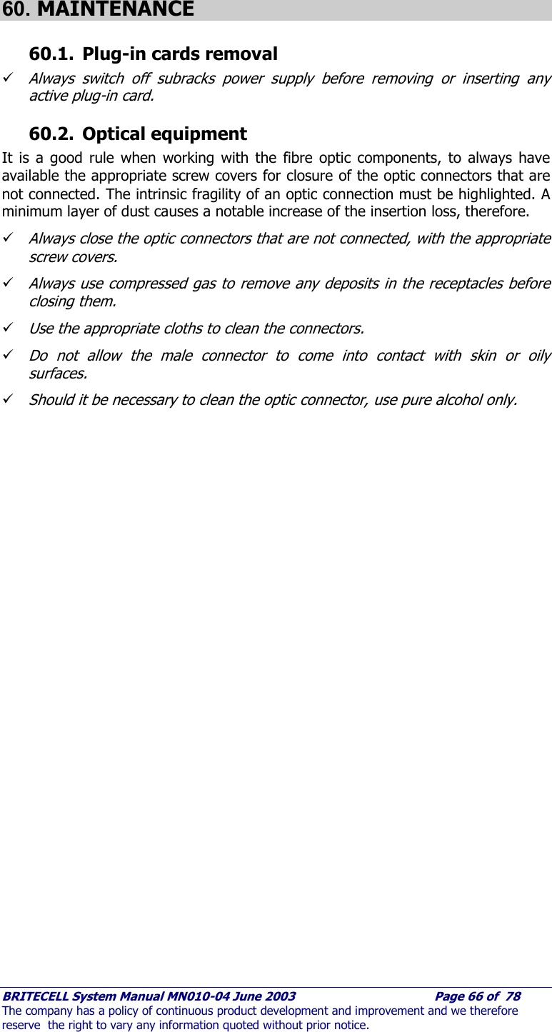
![BRITECELL System Manual MN010-04 June 2003 Page 45 of 78 The company has a policy of continuous product development and improvement and we therefore reserve the right to vary any information quoted without prior notice. 33.2. Uplink operation The RF signal coming from the mobile through the TFA and TFL in the uplink direction may not be an optimal level. When this is the case, the uplink attenuator is used to prevent the BTS from being over driven. 34. Installation and cabling 34.1. TPR housing The TFL-BSI is a modular plug-in card designed to be put in a 6 HE sub-rack (TPR family). The TFL-BSI interfaces with the BTS transmitter and receiver through N-female connectors and with Britecell with SMA-female connectors. The connection with the BTS may be direct, if the BTS’s transmitter and receiver are separated, or through a circulator or a common path RF combiner (please refer also to THYB section). When the system is air interfaced through a repeater a common path RF combiner is required in order to separate the uplink and downlink path. The connection between TFL-BSI and Local Units may be direct or through a combiner stage (please refer to TLC section) depending on the system’s configuration. 35. Calculation of attenuation setting 35.1. Downlink Calculation of Downlink TFL-BSI setting is made in order to supply Britecell Local Unit with correct DL input power. MaxBCDLNetbCCpouplerDirInputPOIDLBSI PILILPA __.om._@_ )(]dB[ −−−= where: P@POI_Input [dBm/c]= RF power level per carrier at POI input: ILDir.Coupler [dB]= Directional coupler insertion loss (if present); ILComb.Net. [dB]= Combining Network insertion loss; PDL_BC_Max [dBm/c]= Max input power per carrier at Local Unit input. 35.2. Uplink Calculation of Uplink TFL-BSI setting is made to meet BTS uplink blocking requirements. SMPILILPA BlockingBTSNetbCCpouplerDirBlockingULLUblkULBSI +−+−= @.om.@___ )]([]dB[ where: PLU_UL@Blocking [dBm]= Local Unit output power when Remote Unit is at blocking level (3 dB C/N degradation); PBTS@Blocking [dBm]= BTS receiver blocking level; SM = Safe margin (typically 3 dB).](https://usermanual.wiki/Andrew-Wireless-Innovations-Group/BCEL-400.Manual-2-0f-2/User-Guide-354067-Page-10.png)


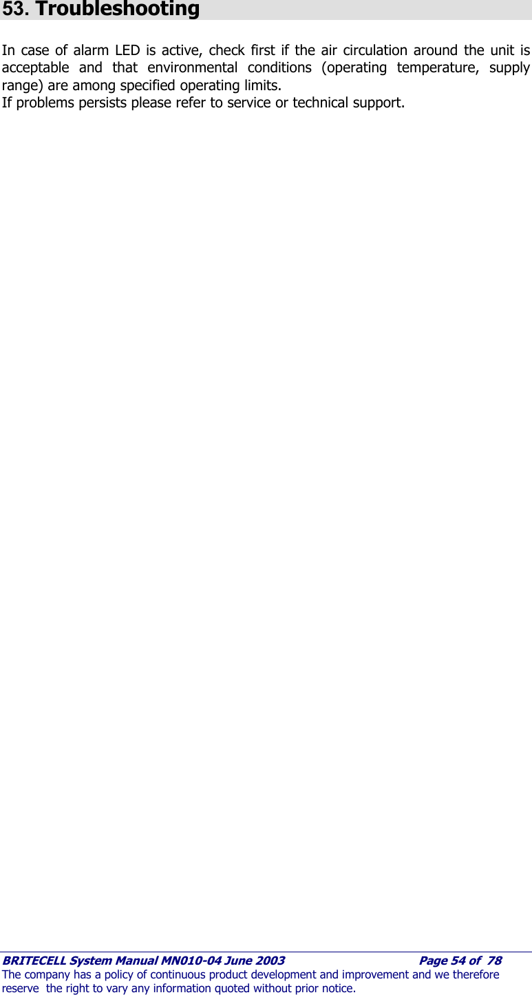
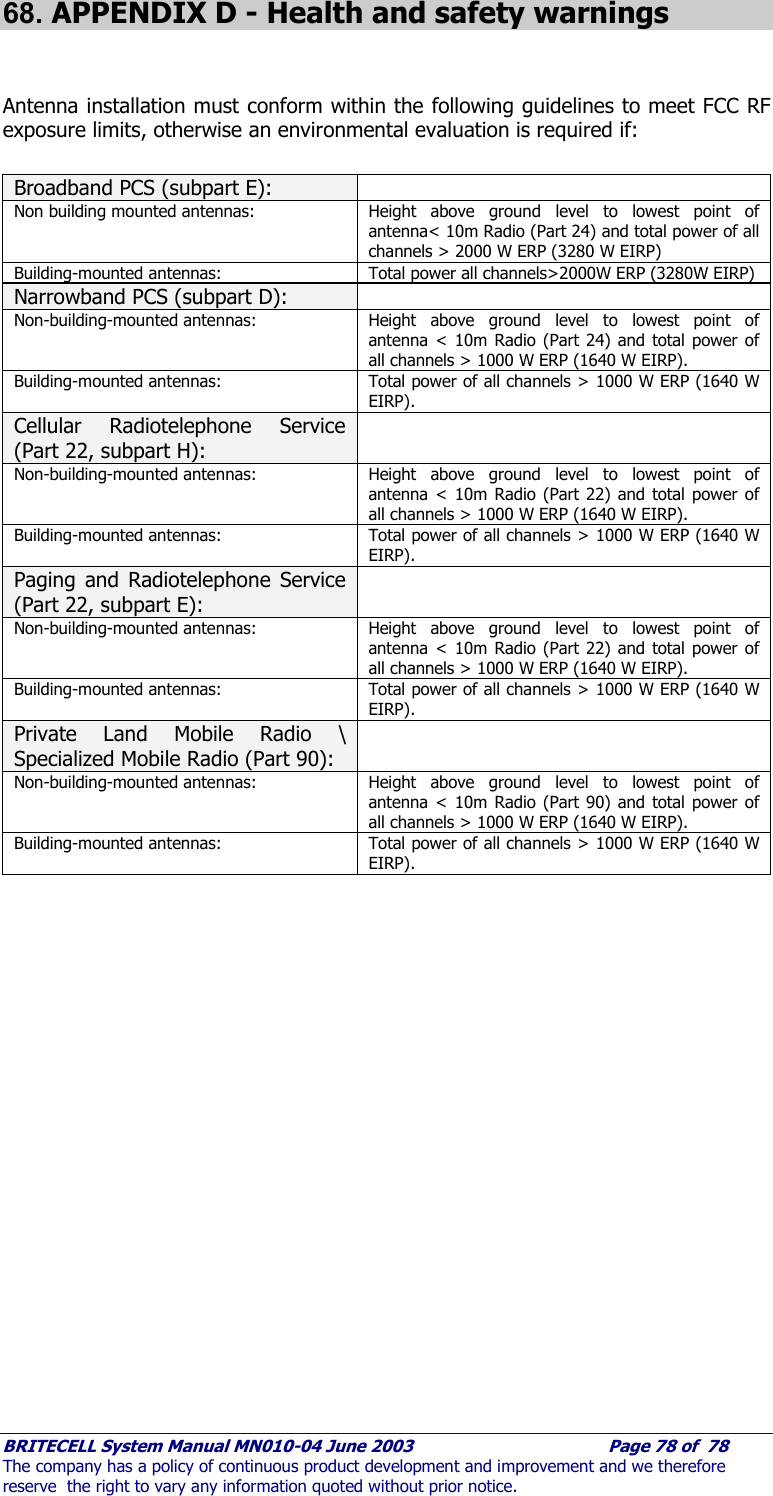
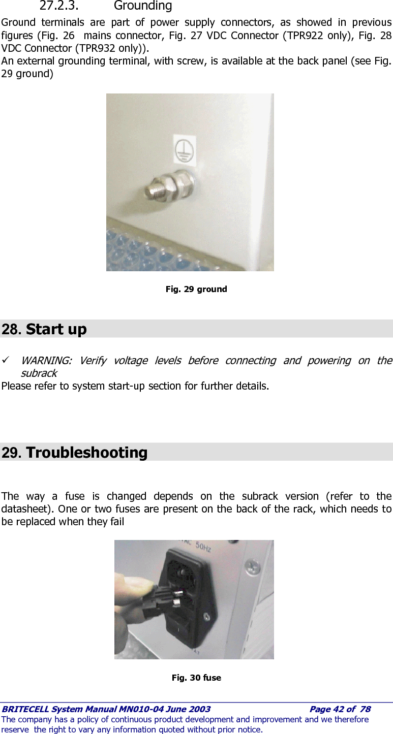
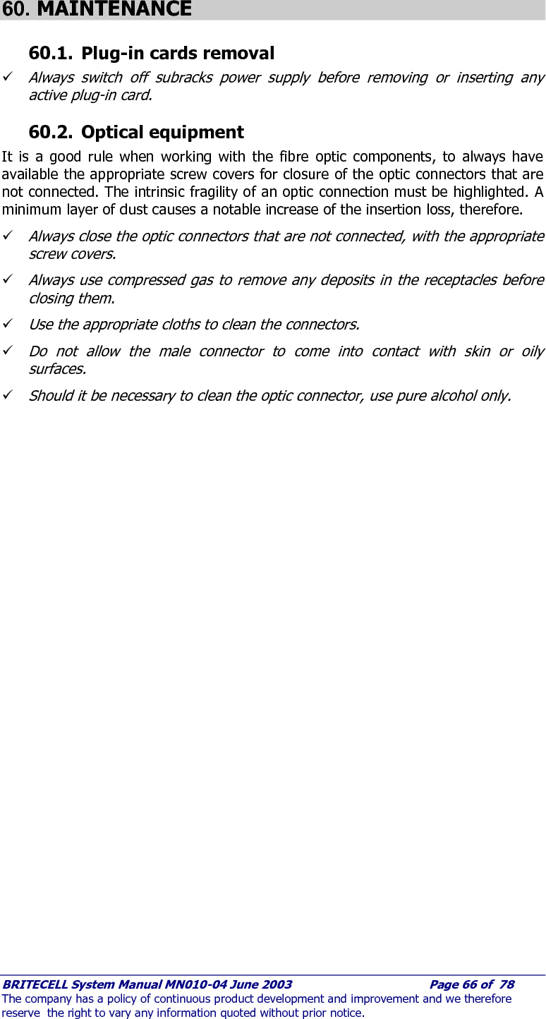
![BRITECELL System Manual MN010-04 June 2003 Page 65 of 78 The company has a policy of continuous product development and improvement and we therefore reserve the right to vary any information quoted without prior notice. 58.4. Power Supply A Britecell system may be locally (at each remote unit) or distributed powered. There are advantages with both methods. It may be faster and cheaper to use local power, however it is easier to back-up a system when the power originates at a single point. A power supply may be distributed in a composite cable (copper and fiber), or two separately parallel cables may be run. Note that the cable containing the copper conductors must carry the appropriate plenum rating and must be of sufficient conductor area to ensure adequate voltage at the furthest Remote Unit under full load. Refer to TFA datasheet for power consumption specifications. If Local Units subrack is to be co-located with a BTS it is often desirable to power the entire system from the battery-backed low voltage supply available. The Local Unit card is fitted with a universal AC power supply module but can be ordered with -48VDC modules instead. The overall power consumption of a full equipped subrack will not exceed 110W. A general rule for subrack power consumption is: (Local Unit consumption [W]) x (cards number) / 0.75 = overall consumption [W] 59. SYSTEM START-UP In order to avoid damaging the equipment, the following criteria must be used to start up the system: 1. Verify all the power supply connections. 2. Verify all the RF connections. 3. Verify all the optical connections. 4. Set all the adjustable attenuators on the TFL-BSI at the maximum value of attenuation. 5. Switch on the local units sub-racks. 6. Check for alarm status and in case of alarm refer to troubleshooting paragraph. 7. Connect the spectrum analyser at the input of one TFL and measure the level of the carriers for every operator. 8. Set the adjustable attenuators in order to have the right level of the carriers at the input of the TFL according to the technical specifications.](https://usermanual.wiki/Andrew-Wireless-Innovations-Group/BCEL-400.Manual-2-0f-2/User-Guide-354067-Page-30.png)
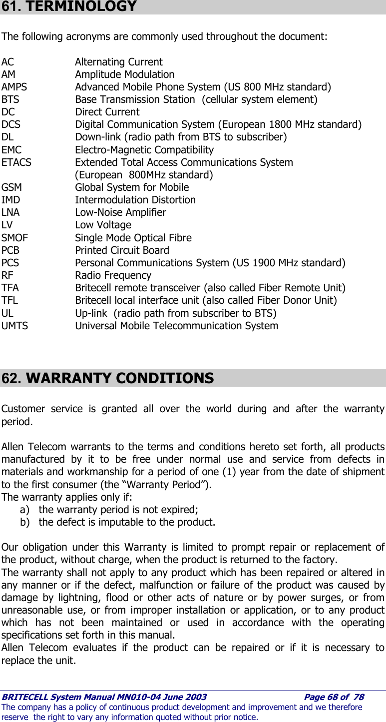

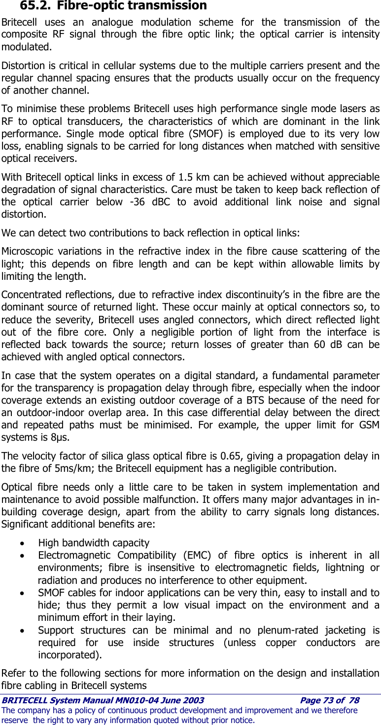
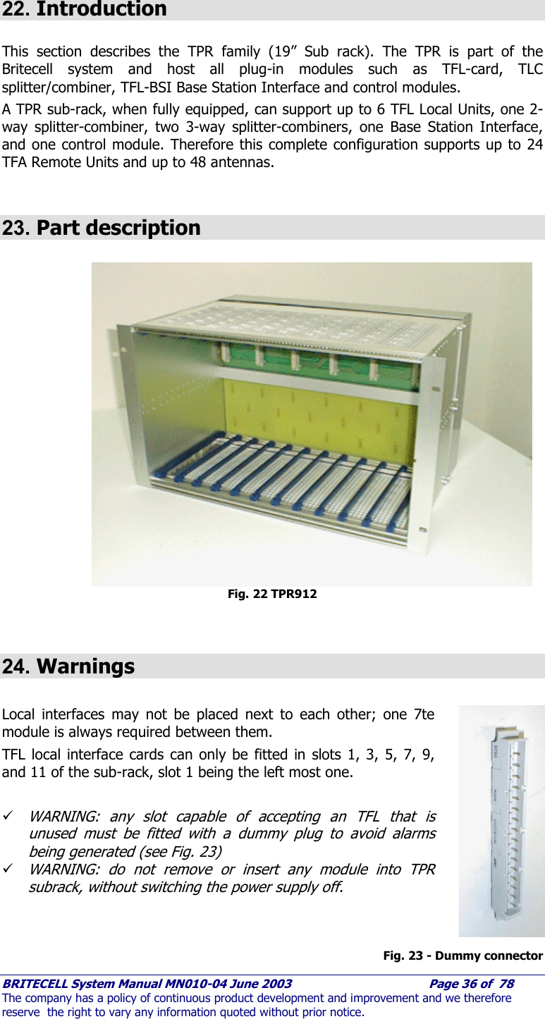
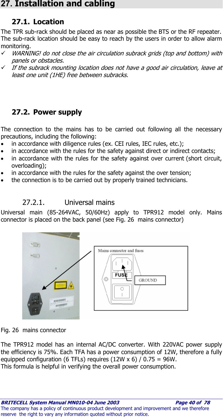
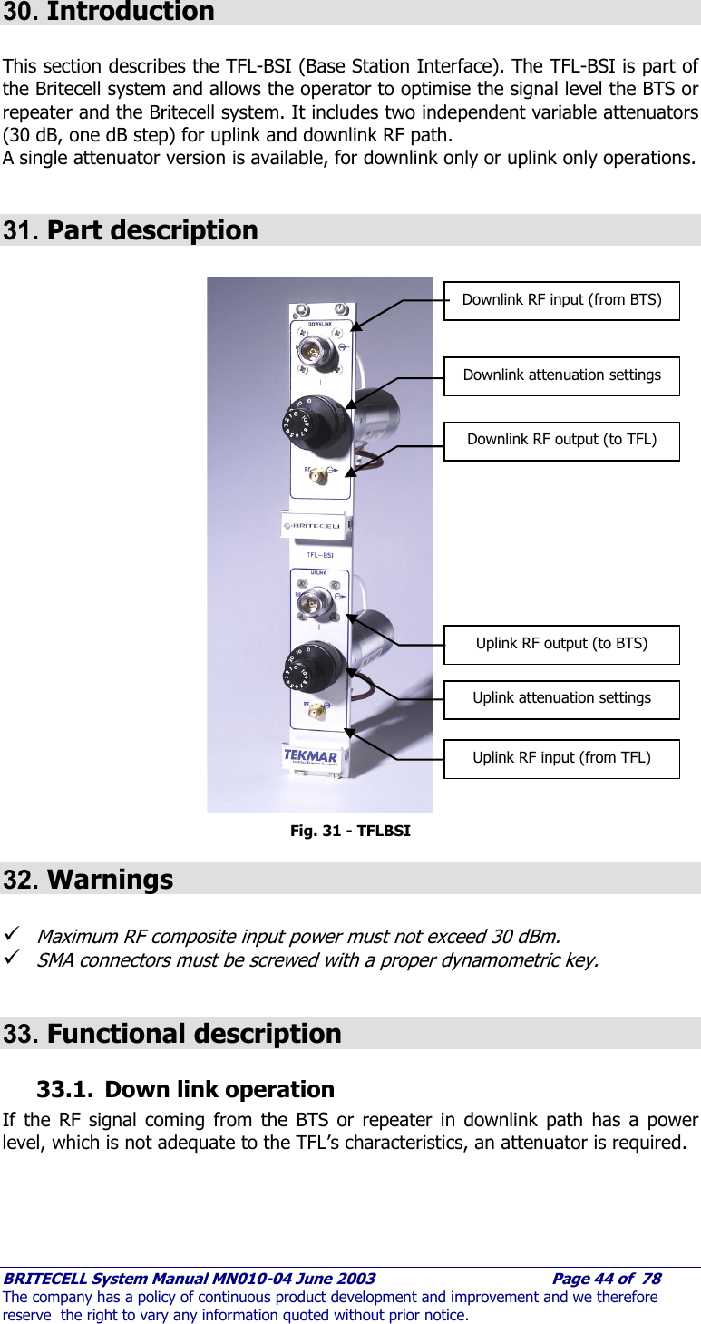
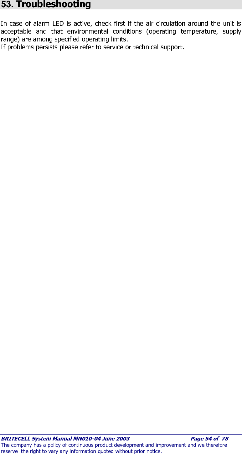
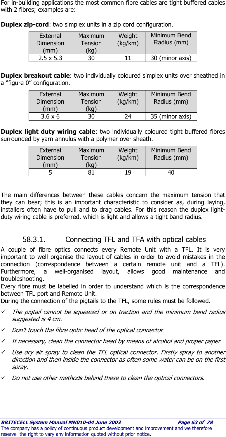
![BRITECELL System Manual MN010-04 June 2003 Page 75 of 78 The company has a policy of continuous product development and improvement and we therefore reserve the right to vary any information quoted without prior notice. 66. APPENDIX B - Britecell input power level setting 66.1. Down link power levels In order to achieve spurious products below the limits set forth in various governmental specifications (eg. -36 dBm for GSM900, –30 dBm for GSM1800) the input power at the TFL downlink input port should be set according to the following table. FCC specifications (-13 dBm- AMPS, PCS) are somewhat more lenient and are also dependent on spectral mask requirements. NUMBER OF CARRIERS (N) Max power per carrier at TFL DL RF input (a) PIN TFL /carrier [dBm] Max power per carrier at TFA RF output (b) POUT TFA /carrier [dBm] 2 3,0 10,0 3 0,7 7,7 4 -0,3 6,7 5 -1,2 5,8 6 -1,8 5,2 7 -2,3 4,7 8 -2,7 4,3 9 -3,1 3,9 10 -3,4 3,6 11 -3,7 3,3 12 -4,0 3,0 14 -4,5 2,5 16 -4,9 2,1 18 -5,2 1,8 20 -5,6 1,4 22 -5,8 1,2 26 -6,4 0,6 30 -7,1 -0,1 34 -7,6 -0,6 40 -8,3 -1,3 NOTES: DL power levels for Britecell 900 MHz and Britecell 1800 MHz TFLxxxx4H-x TFL DL RF input TFL UL RF output a b b TFAxxxx](https://usermanual.wiki/Andrew-Wireless-Innovations-Group/BCEL-400.Manual-2-0f-2/User-Guide-354067-Page-40.png)
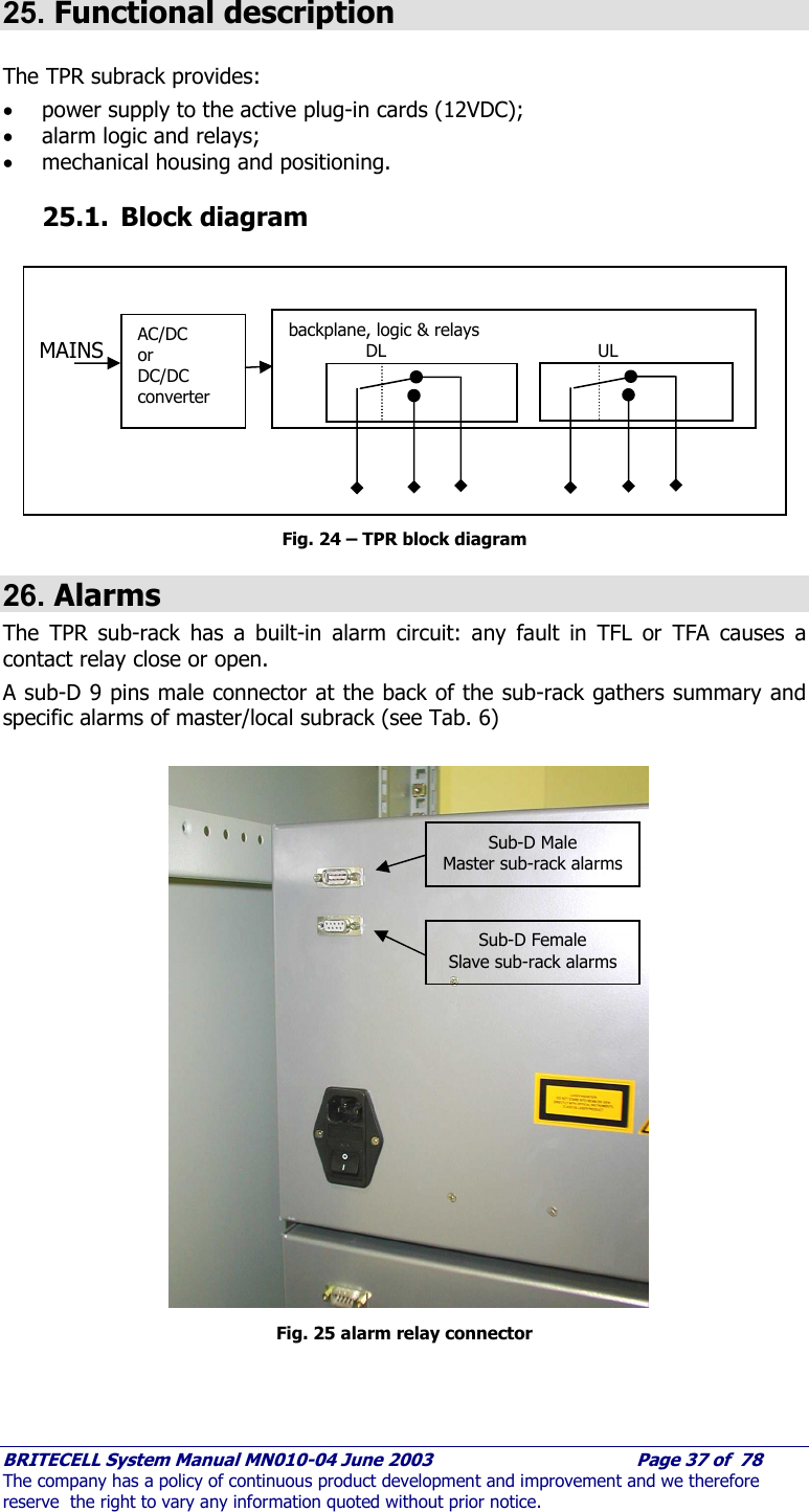
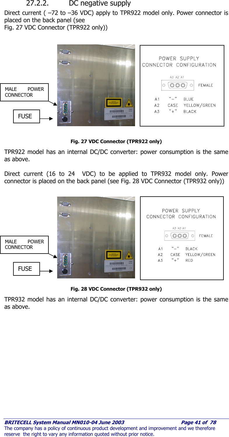
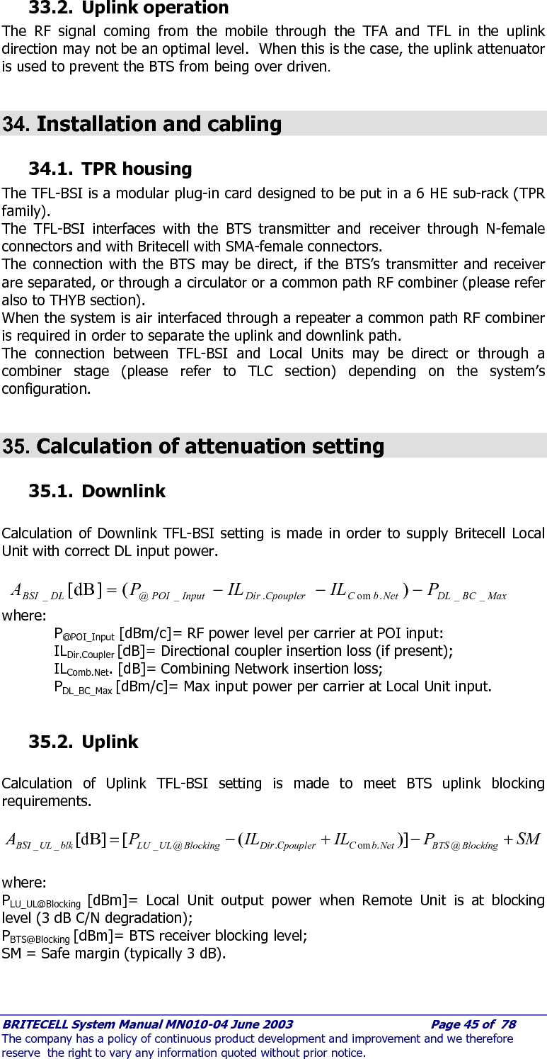
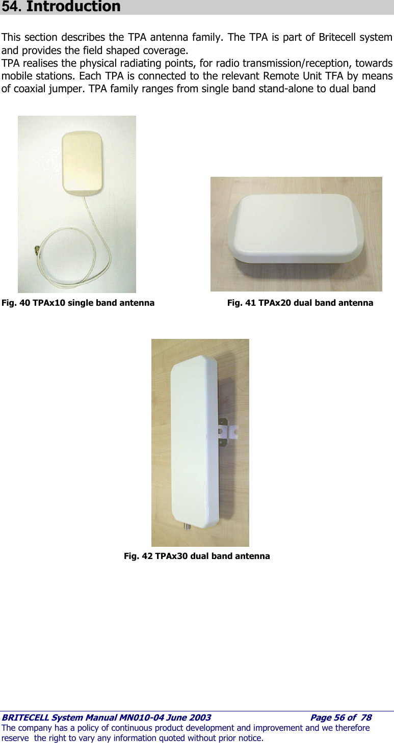
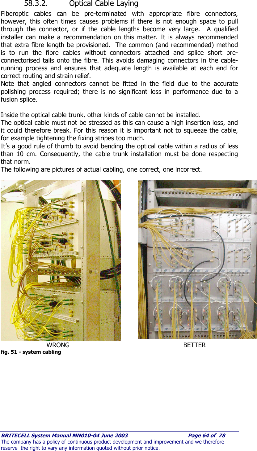
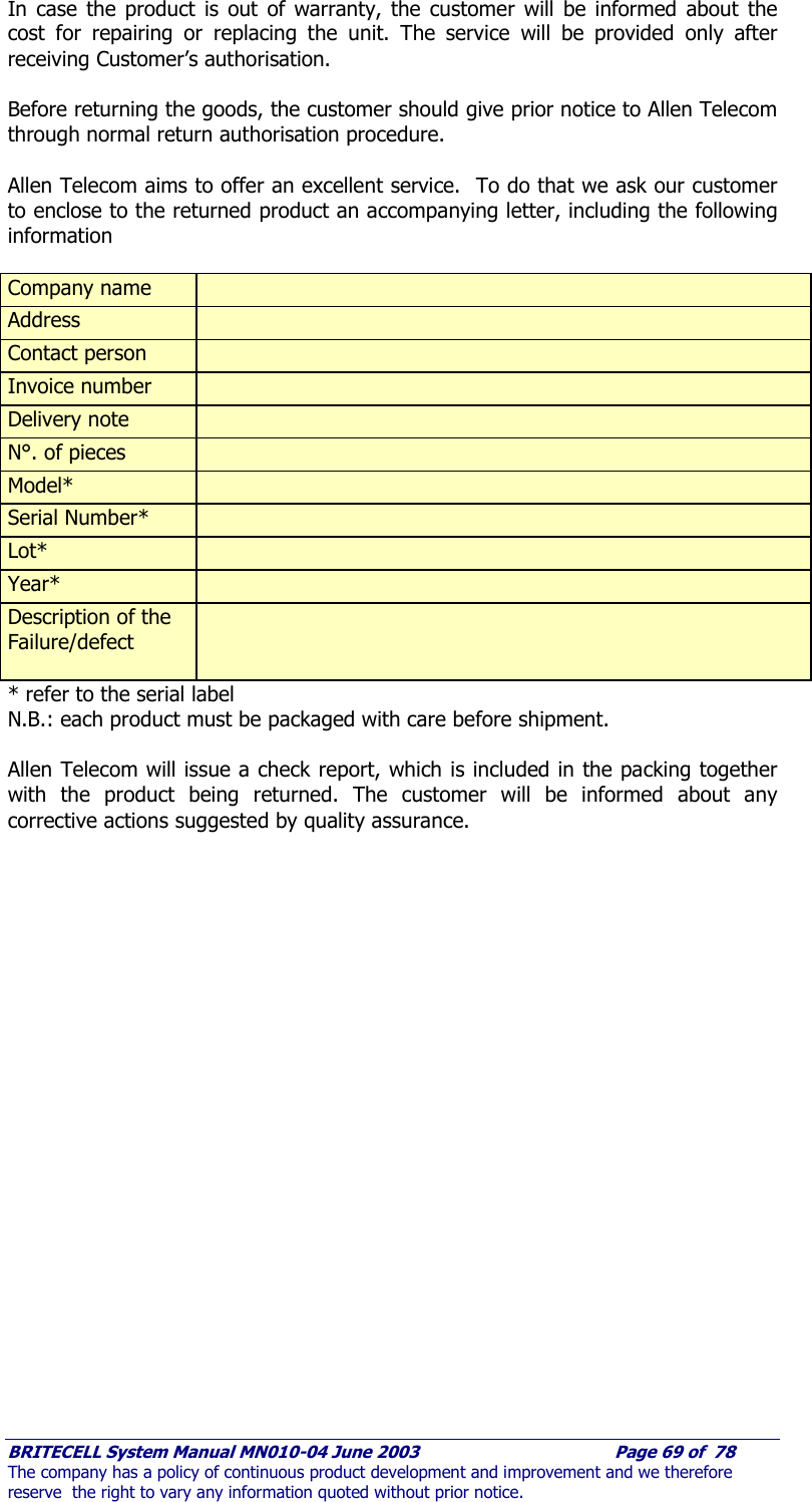
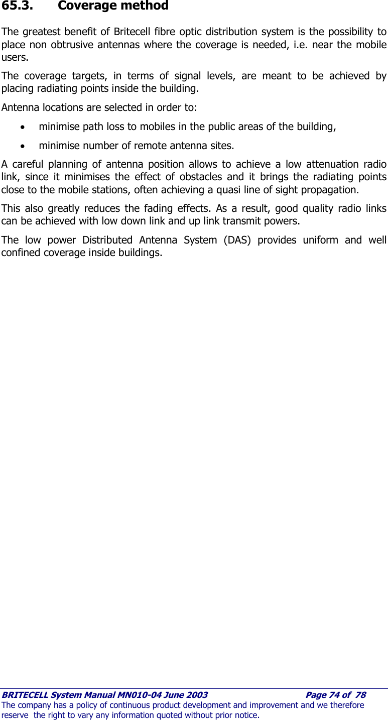
![BRITECELL System Manual MN010-04 June 2003 Page 76 of 78 The company has a policy of continuous product development and improvement and we therefore reserve the right to vary any information quoted without prior notice. 66.2. Down link power levels: remote unit + booster NUMBER OF CARRIERS (N) Max power per carrier at TFL DL RF input (a) PIN TFL /carrier [dBm] Max power per carrier at TFA RF output (b) POUT TFA /carrier [dBm] Max power per carrier at TFB RF output (c) POUT TFB /carrier [dBm] 1 0,0 7,0 20,0 2 -4,0 3,0 16,0 3 -6,3 0,7 13,7 4 -7,3 -0,3 12,7 5 -8,2 -1,2 11,8 6 -8,8 -1,8 11,2 7 -9,3 -2,3 10,7 8 -9,7 -2,7 10,3 9 -10,1 -3,1 9,9 10 -10,4 -3,4 9,6 11 -10,7 -3,7 9,3 12 -11,0 -4,0 9,0 14 -11,5 -4,5 8,5 16 -11,9 -4,9 8,1 18 -12,2 -5,2 7,8 20 -12,6 -5,6 7,4 22 -12,8 -5,8 7,2 26 -13,3 -6,3 6,7 30 -13,8 -6,8 6,2 34 -14,1 -7,1 5,9 40 -14,6 -7,6 5,4 NOTES: DL power levels for Britecell 900 MHz + TFB915 DL power levels for Britecell 1800 MHz + TFB1815 The DL levels at Booster output assume that the cable connecting TFA and booster has 1 dB loss. TFLxxxx4H-x TFL DL RF input TFL UL RF output a b b c TFBxxxx TFAxxxx](https://usermanual.wiki/Andrew-Wireless-Innovations-Group/BCEL-400.Manual-2-0f-2/User-Guide-354067-Page-41.png)