Andrew Wireless Innovations Group BCEL-FAST819 Repeater User Manual mn021 01
Andrew Wireless Innovations Group Repeater mn021 01
UserManual.wiki
>
Andrew Wireless Innovations Group
>
BCEL FAST819 User Manual
Manual
Navigation menu
Upload a User Manual
Namespaces
Wiki Guide
HTML
PDF
Info
Views
User Manual
Discussion / Help
Navigation

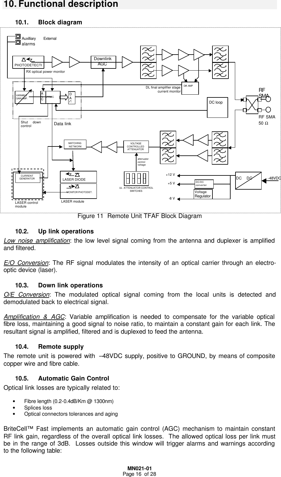
![MN021-01 Page 7 of 28 4.2. Services The BriteCell™ Fast system operates at the following standards: 4.3. Functional description The BriteCell™ Fast system is a fibre optic distribution system for wireless signals. It consists of a donor unit (TFLF) feeding up to 4 remote units (TFAF) in a star topology. Each remote unit directly feeds up to two coverage antennas. The connection between the BTS and BriteCell™ FAST system can either be direct or through a repeater via a duplexed N-connector. Both donor and remote units are powered at –48VDC (telecom supply). Donor and remote units shall be connected with pre-connectorized composite fibre optic cable (cable with twin optical fibre and copper wire for remote supply). The system installation doesn’t require any particular calculation or setting, making it a real plug-and-play system. Some useful functionalities, software and hardware, simplifies diagnostic and commissioning: • Downlink optical power test point • Uplink adjustable gain setting • Link diagnostic by means of individual link LEDs • Downlink ALC (Automatic Level Control) • Optical AGC (Automatic Gain Control) The following picture shows a simplified system block diagram Figure 2 Britecell™ Fast System Block Diagram SERVICE BANDWIDTH Uplink [MHz] Downlink[MHz] TRUNKING RADIO 806:824 851:869 AMPS 824:849 869:894 GSM 890:915 935:960 DCS 1710:1785 1805:1880 PCS 1850:1910 1930:1990 E-GSM 880:915 925:960 BTS Local Unit Mixed fibre-copper cable Unit Remote Unit Mixed fibre-copper cable Mixed fibre-copper cable Mixed fibre-copper cable Fixed Attenuator](https://usermanual.wiki/Andrew-Wireless-Innovations-Group/BCEL-FAST819/User-Guide-170306-Page-9.png)

![MN021-01 Page 26 of 28 24.3. Antennas Positioning Starting with the parameters determined as defined above, the number of radiating points can be defined. The calculations needed can be implemented in a tool. The number of carriers is used to define the TFA/TFAF RF Output Power (POUT TFA in Figure 18) according to the table in Appendix C. As a rule of thumb, the power values for a double number of carriers is obtained reducing the Power value of 3dB. Figure 18 Diagram for Power Calculations According to line-of-sight conditions, the calculation of the maximum coverage distance is performed using the Free-space propagation formula. This formula is adapted to propagation in indoor environments introducing an appropriate propagation index and including margin against fading. 24.3.1. EIRP calculation: ][_][][][ ][ dBCableRFdBSplitterdBiyDirectivitdBmTFAFOUTdBm AAGPEIRP −−+= where; POUT TFAF = Remote Unit RF connector Output Power; GDirectivity = Directivity Gain of the Antenna; ASplitter = Splitter Insertion loss; ARF_Cable = RF Cable Loss. 24.3.2. Max Coverage Distance Calculation: PLdBmRxdBWallsdBdBmExpPAMFEIRPmmto_Prx_minDistanceMax 110][][ )10(4_]min[_][][][ −−−⋅=πλwhere; MF = Margin against Fading; AWalls = Walls supplementary Attenuation; PRx-min = Minimum Required Power Level; ExpPL = Path Loss Exponent (propagation index); λ = Wavelength. The results can detailed for different Remote Unit configuration (splitter insertion loss, RF cable length, additional attenuation e.g. walls). ü Depending on the number of RF carriers, the antenna type and the RF cables type, the maximum distance that the system is able to perform is estimated. This calculation is used to plan antenna positioning so that the project requirement (Minimum Down Link Power Level) is met. ü Technical Suggestion: The design is an iteration process so it’s advisable to start from the hypothesis that the Cable Loss and the Antenna Gain compensate each other and consequently the EIRP is equal to the TFA Output Power. To reach a good coverage, a target is to choose the antenna positioning in order to maximize Line of Sight. TFA Fiber Remote Unit TFAF Fiber Remote Unit TFLF Fiber Donor Unit POUT TFAF RF Cable LossAntenna Gain PIN TFLF](https://usermanual.wiki/Andrew-Wireless-Innovations-Group/BCEL-FAST819/User-Guide-170306-Page-28.png)