Andrew Wireless Innovations Group BCEL-FAST819 Repeater User Manual mn021 01
Andrew Wireless Innovations Group Repeater mn021 01
Manual

U
US
SE
ER
R
I
IN
NS
ST
TA
AL
LL
LA
AT
TI
IO
ON
N
M
MA
AN
NU
UA
AL
L
MN021-01
Page 1 of 28
INDEX
1. Installation & safety requirements.............................................................................................................................3
1.1. Environmental conditions:...........................................................................................................................3
1.2. Installation site features ..............................................................................................................................3
1.3. Connection to the power.............................................................................................................................3
1.4. Safety and precautions during the installation.............................................................................................3
1.5. Safety and precautions for lasers................................................................................................................3
1.6. Connector care and cleaning......................................................................................................................4
2. Warning labels ..........................................................................................................................................................4
3. Health and safety warnings.......................................................................................................................................5
4. System description....................................................................................................................................................6
4.1. Features......................................................................................................................................................6
4.2. Services ......................................................................................................................................................7
4.3. Functional description.................................................................................................................................7
5. Functional description...............................................................................................................................................9
5.1. Block diagram.............................................................................................................................................9
5.2. Down link operations...................................................................................................................................9
5.3. Up link operations .......................................................................................................................................9
5.4. Remote supply..........................................................................................................................................10
5.5. Automatic Gain Control.............................................................................................................................10
6. Alarms and settings ................................................................................................................................................10
6.1. Alarm contacts..........................................................................................................................................11
6.2. UL level setting .........................................................................................................................................11
6.3. Software auto-configuration......................................................................................................................11
7. Installation and Cabling...........................................................................................................................................12
7.1. Power supply ............................................................................................................................................12
7.2. RF Ports....................................................................................................................................................13
7.3. Optical fibres connection...........................................................................................................................13
8. Troubleshooting......................................................................................................................................................14
9. Part description.......................................................................................................................................................15
10. Functional description...........................................................................................................................................16
10.1. Block diagram...........................................................................................................................................16
10.2. Up link operations .....................................................................................................................................16
10.3. Down link operations.................................................................................................................................16
10.4. Remote supply..........................................................................................................................................16
10.5. Automatic Gain Control.............................................................................................................................16
11. Alarms and settings ..............................................................................................................................................17
11.1. Remote unit LEDs .....................................................................................................................................17
11.2. External alarms .........................................................................................................................................17
12. Installing and cabling.............................................................................................................................................18
12.1. Power supply ............................................................................................................................................18
12.2. RF Ports....................................................................................................................................................18
12.3. Optical fibres connection...........................................................................................................................18
12.4. Test point..................................................................................................................................................19
13. Troubleshooting....................................................................................................................................................19
14. Installation and cabling..........................................................................................................................................20
14.1. Local unit location.....................................................................................................................................20
14.2. Remote unit and antennas location...........................................................................................................20
14.3. Power Supply............................................................................................................................................20
15. System start-up.....................................................................................................................................................20
16. Maintenance.........................................................................................................................................................20
17. Warranty conditions ..............................................................................................................................................21
18. Technical support..................................................................................................................................................22
19. Appendix A : Installation checklist.........................................................................................................................22
20. Appendix B – Technical specifications..................................................................................................................23
21. Appendix C – Mechanical outline..........................................................................................................................24
22. Appendix D – Power levels ...................................................................................................................................25
23. Appendix E – Using external attenuator................................................................................................................25
24. Appendix f – System Design Guidelines ...............................................................................................................25
24.1. Introduction...............................................................................................................................................25
24.2. Project Definition.......................................................................................................................................25
24.3. Antennas Positioning ................................................................................................................................26
25. Appendix G - Classifying hazardous areas ..........................................................................................................27
MN021-01
Page 2 of 28

MN021-01
Page 3 of 28
GENERAL INFORMATION
1. Installation & safety requirements
1.1. Environmental conditions:
This equipment is designed for indoor use.
Operating temperature: +5 to +40°C
Do not install in corrosive atmosphere or in critical environmental conditions such as hazardous
classified areas (see appendix G).
1.2. Installation site features
The local unit should be installed in a dry and suitable location where:
• No explosion risks are present;
• The environment is not classified as high-risk in case of fire;
• Suspended particles are not in great concentration;
• The environment is not subject to any traffic which could cause crash damages;
• The site is properly located with respect to the ergonomic positioning of the working environments;
• The system is placed in a private room, protected against any possible violation;
• The system must not be exposed to ultra-violet rays;
• The site must be accessible by maintenance personnel;
• The site must be dry, with low humidity;
• The site must guarantee proper space for cables and natural ventilation to the system;
• A two meter separation from any heating opening is kept.
The remote units should be mounted in reasonable locations as well:
• Do not install inside heating or conditioning units;
• Do not install inside cable pipeline, fire-prevention site, fire escape, lift tunnels, emergency exits, which have to
guarantee defined safety standards;
• Remember that the temperature in the upper part of a room is higher than at 2 meters height. For false ceiling
installation, verify that the environment temperatures do not exceed allowed limits;
• The remote unit transmits the RF signal and safety distance for RF radiation must be respected;
• The units must be accessible for tests and maintenance.
1.3. Connection to the power
The connection to the power has to be carried out using the following precautions:
• It must be properly made according to the due diligence rules (IEC rules, etc.);
• In accordance with the rules for the safety against direct or indirect contacts;
• In accordance with the rules for the safety against the over current (short circuit, overloading);
• In accordance with the rules for the safety against over tension;
• The connection is to be carried out by proper and competent staff.
1.4. Safety and precautions during the installation
The following means and tools will be needed for installation:
• Typical electrician tools: cross-point screwdriver, scissors, pliers, nippers, drill and bits, screw for fixing local
and remote units to the wall.
• Typical means: Proper ladder, scaffolding or air platform for ceiling installation of remote units.
• Caution should be used when installing at a height upper than 2 meters. Personnel who are installing this
equipment should be informed about the possible risks and safety measures when elevated.
1.5. Safety and precautions for lasers
The laser used in BriteCell contains an optical transmitter, which has a power level that is not
dangerous to a person's health. However, it is classified as class III A or Class 1 (European norm
EN60825) equipment. Nevertheless, it is prudent in the installation phase to observe the
following rules:
ü Never look directly at the internal optic connector of the transmitter apparatus when it is switched on. The
wavelength of the laser is not visible to the human eye, which means that long-term damage will not immediately
be known.
ü When working with the optical connectors, verify at each end that both transmitting lasers are switched off.
MN021-01
Page 4 of 28
1.6. Connector care and cleaning
Connectors for single mode optical fibre are designed for sub micron tolerances. Such a
connector has an optical section of only 9 µm diameter. The optical connector is a high
precision device. It must be handled with care, to avoid scratches and other mechanical/optical
damages that will impair or reduce the system’s performance
The following rules must be carefully followed:
ü Do not leave optical connectors open, as they will attract dirt.
ü Do not touch the connector tip. Clean it with a proper tissue before inserting it into the sleeve.
ü Use pure ethyl alcohol for improved cleaning.
ü Sleeves may be cleaned by injecting pure gas under pressure.
ü Do not attempt to insert connectors mechanically incompatible. This will result in severe damage.
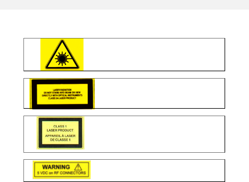
2. Warning labels
Caution! - Invisible laser radiation from this
aperture
Caution! Laser radiation. Do not stare into
the beam or view directly with optical
instruments - CLASS 3A laser product
Caution! - Laser radiation. Do not stare into
the beam or view directly with optical
instruments - CLASS 1 laser product
Warning! – 5Vdc on RF connectors. Avoid
connecting testing equipment to the RF ports.

MN021-01
Page 5 of 28
3. Health and safety warnings
Antenna installation must conform within the following guidelines to meet FCC RF exposure
limits, otherwise an environmental evaluation is required if:
Broadband PCS (subpart E):
Non building mounted antennas: Height above ground level to lowest point of antenna < 10m
Radio (Part 24) and total power of all channels > 2000 W ERP
(3280 W EIRP)
Building-mounted antennas: Total power all channels>2000W ERP (3280W EIRP)
Narrowband PCS (subpart D):
Non-building-mounted antennas: Height above ground level to lowest point of antenna < 10m
Radio (Part 24) and total power of all channels > 1000 W ERP
(1640 W EIRP).
Building-mounted antennas: Total power of all channels > 1000 W ERP (1640 W EIRP).
Cellular Radiotelephone Service
(Part 22, subpart H):
Non-building-mounted antennas: Height above ground level to lowest point of antenna < 10m
Radio (Part 22) and total power of all channels > 1000 W ERP
(1640 W EIRP).
Building-mounted antennas: Total power of all channels > 1000 W ERP (1640 W EIRP).
Paging and Radiotelephone
Service (Part 22, subpart E):
Non-building-mounted antennas: Height above ground level to lowest point of antenna < 10m
Radio (Part 22) and total power of all channels > 1000 W ERP
(1640 W EIRP).
Building-mounted antennas: Total power of all channels > 1000 W ERP (1640 W EIRP).
Private Land Mobile Radio\
Specialized Mobile Radio (Part 90):
Non-building-mounted antennas: Height above ground level to lowest point of antenna < 10m
Radio (Part 90) and total power of all channels > 1000 W ERP
(1640 W EIRP).
Building-mounted antennas: Total power of all channels > 1000 W ERP (1640 W EIRP).
IMPORTANT NOTE: To comply with FCC RF exposure compliance requirements, the following
antenna installation and device operating configurations must be satisfied: A separation
distance of at least 20 cm must be maintained between the antenna of this device and all
persons. RF exposure compliance may need to be addressed at the time of licensing, as
required by the responsible FCC Bureau(s), including antenna co-location requirements of
1.1307(b)(3). Maximum permissible antenna gain is:
for the BCR-BCEL FAST719 is 15.4 dBi. (Version TFAF731xx, TFLF734xx)
for the BCR-BCEL-FAST819 is 11.5 dBi. (Version TFAF23xx, TFLF23xx)
For any clarification, please refer to FCC rules, 47 CFR ch. I, part 1.1307
MN021-01
Page 6 of 28
BRITECELL FAST
4. System description
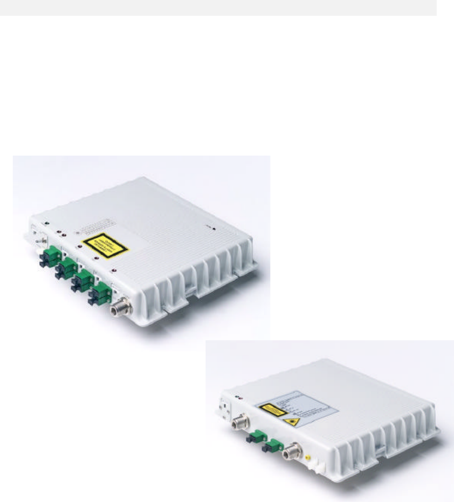
BRITECELL™ FAST is a plug and play fibre optic distributed antenna kit, offering the most
suitable solution for indoor coverage in small areas. The package includes up to four compact
RF remote transceivers (TFAF), driven by one local distribution unit (TFLF). It is available in
various frequency ranges (from 800MHz up to 2200 MHz) satisfy the requirements of 2nd and 3rd
generation mobile networks for simple coverage needs.
The TFLF local unit has been properly designed into a stand-alone mechanical case, including
all required ancillary and support functions. The kit includes up to four standard TFAF remote
units and a composite fiber-copper cable to connect them to the local unit. The installed remote
units can be retained in case of system expansion to a fully modular BriteCell configuration,
both single band or dual band, with a minimum setting effort.
Figure 1 Local Unit (TFLF, left) and Remote Unit (TFAF, right)
4.1. Features
Ideal complement to low-power pico BTS or repeater:
• Single band
• Up to 1.5 km optical links
• Wide dynamic range
• Very low power consumption
• Compact and small size
• Easy to install
• Remote alarms
• Plug & play
• Composite cable included
MN021-01
Page 7 of 28
4.2. Services
The BriteCell™ Fast system operates at the following standards:
4.3. Functional description
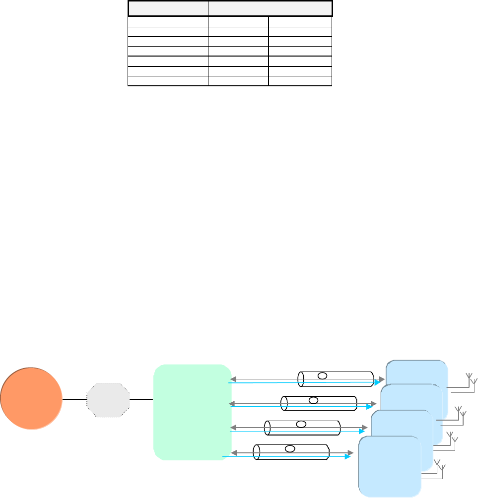
The BriteCell™ Fast system is a fibre optic distribution system for wireless signals. It consists of
a donor unit (TFLF) feeding up to 4 remote units (TFAF) in a star topology. Each remote unit
directly feeds up to two coverage antennas. The connection between the BTS and BriteCell™
FAST system can either be direct or through a repeater via a duplexed N-connector.
Both donor and remote units are powered at –48VDC (telecom supply). Donor and remote units
shall be connected with pre-connectorized composite fibre optic cable (cable with twin optical
fibre and copper wire for remote supply).
The system installation doesn’t require any particular calculation or setting, making it a real
plug-and-play system. Some useful functionalities, software and hardware, simplifies diagnostic
and commissioning:
• Downlink optical power test point
• Uplink adjustable gain setting
• Link diagnostic by means of individual link LEDs
• Downlink ALC (Automatic Level Control)
• Optical AGC (Automatic Gain Control)
The following picture shows a simplified system block diagram
Figure 2 Britecell™ Fast System Block Diagram
SERVICE BANDWIDTH
Uplink [MHz] Downlink[MHz]
TRUNKING RADIO 806:824 851:869
AMPS 824:849 869:894
GSM 890:915 935:960
DCS 1710:1785 1805:1880
PCS 1850:1910 1930:1990
E-GSM 880:915 925:960
BTS Local
Unit
Mixed fibre-copper cable
Unit
Remote
Unit
Mixed fibre-copper cable
Mixed fibre-copper cable
Mixed fibre-copper cable
Fixed
Attenuator
MN021-01
Page 8 of 28
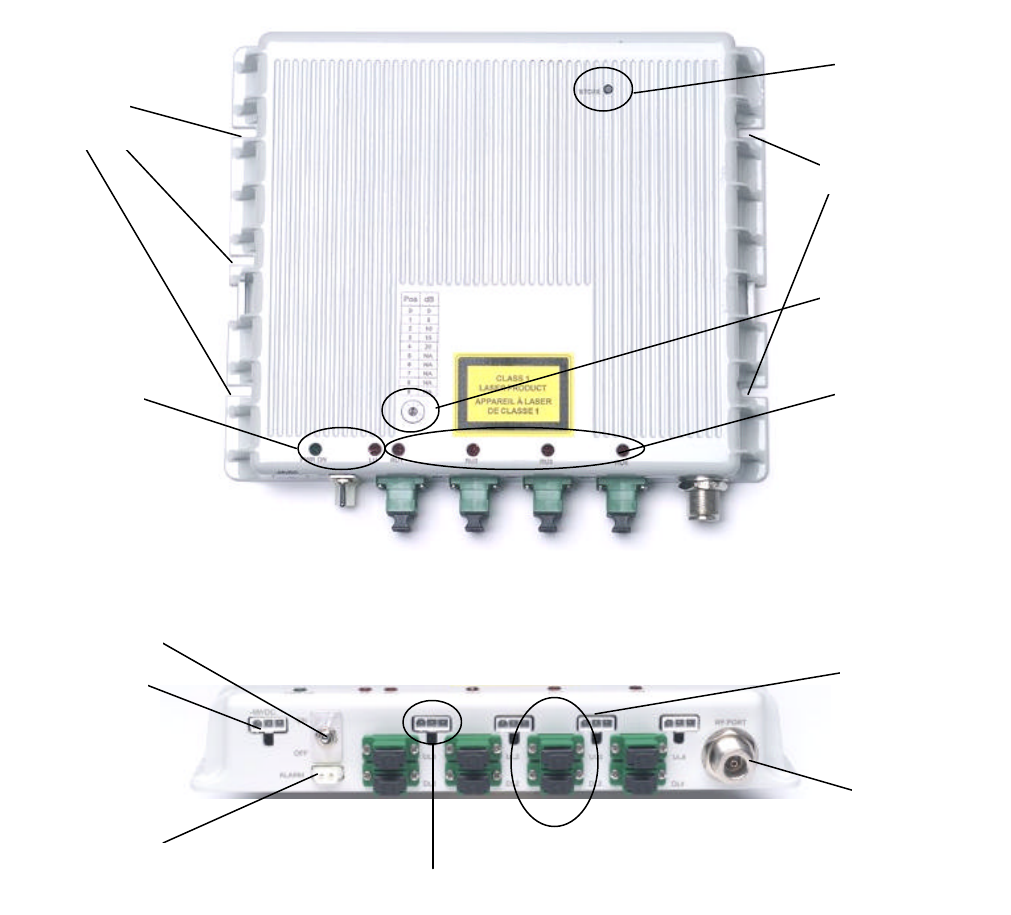
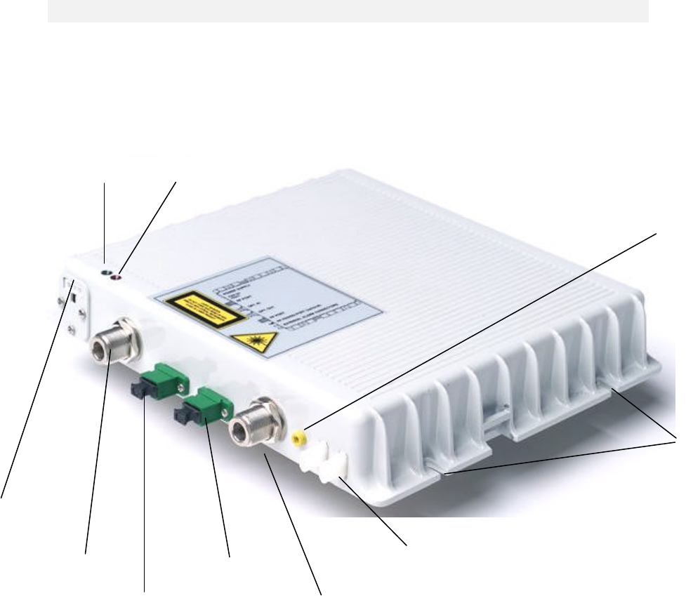
TFLF local unit
Figure 3 Local Unit (TFLF)
Optical UL/DL
connectors to
remote units
Alarm contacts
-48VDC input
Power supply
switch
DL/UL RF port
to BTS
Remote supply connectors
Store button
Step
attenuator
Remote units
alarms and link
status LEDs
Local unit
alarms and
status LEDs
Fittings for
wall fixing
Fittings for
wall fixing
MN021-01
Page 9 of 28
5. Functional description
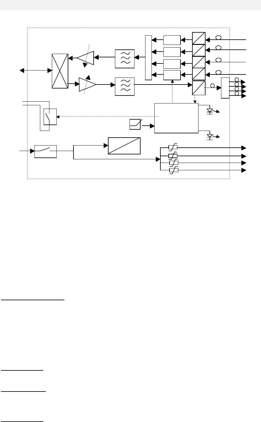
5.1. Block diagram
Figure 4 Local Unit (TFLF) Block Diagram
The Local unit is the core of the system and provides the following functionalities:
• RF low power interface and optical conversion.
• Power supply distribution and short/surge protection.
• Alarm interface through dry contact.
• Status and alarm LEDs.
• Automatic Level Control (ALC) in Downlink for overdriving and spurious emission control.
• Automatic Gain Control (AGC) for Uplink optical path loss compensation.
• Microprocessor based supervision and data communication.
• “Store” button for software auto configuration and alarm masking.
• Step attenuator for uplink gain setting.
5.2. Down link operations
In the downlink path the TFLF fulfils the following operations:
Power level adjustment: The TFLF local unit is designed to be interfaced with a wide range of
low power BTS and repeaters. For higher power BTS’s an external fixed attenuator is required.
Refer to the Appendix for the typical and maximum allowed input levels. Because the RF port is
duplexed, an external attenuator will add the same downlink loss to the uplink path. To
compensate for this loss, the TFLF uplink gain must be adjusted by means of the UL step
attenuator.
The DL RF power is limited from the ALC to avoid spurious emissions in case of overdriving
inputs.
E/O Conversion: The RF signal modulates the intensity of an optical carrier through an electro-
optic device (laser).
Optical Splitting: The modulated optical carrier is split into 4 ways so that it may be transmitted
on a maximum of 4 optical links.
5.3. Up link operations
O/E Conversion: There are 4 O/E conversion devices, or optical receivers, in the TFLF, one for
each optical link. The modulated optical signal coming from the remote units is detected and
E
O
E
O
AGC
E
O
AGC
E
O
AGC
E
O
AGC
UL manual step
Attenuator, 0-20dB
DL ALC
UL
DL
-48V
DL
UL
Alarm
-48V
DC
DC
microcontroller
..
LEDs
…
Alarm Relays
N.O. store
MN021-01
Page 10 of 28
demodulated back to an electrical signal. The data link associated with each remote unit is also
detected and routed to the microprocessor.
Amplification & AGC: Variable amplification is needed to compensate for the variable optical
fibre loss, maintaining a good signal to noise ratio, so that for each link a constant gain is
obtained.
RF Combining: Signals coming from all remotes are combined into a single RF path, filtered and
duplexed into the RF port.
5.4. Remote supply
The local unit provides connection and distribution for –48VDC supply to the remote units, by
means of composite cable, copper wires and optical fibre pairs. Each supply port is protected
against overloads, short and surge with a self-recovery fuse and surge protection. The power
switch will disconnect the remote supply in case of overcurrent.
5.5. Automatic Gain Control
Optical link losses are typically related to:
- Fibre length (0.2-0.4dB/Km @ 1300nm)
- Splices loss
- Optical connectors tolerances and aging
BriteCell™ Fast implements an automatic gain control (AGC) mechanism to maintain constant
RF link gain, regardless of the overall optical link losses. The allowed optical loss per link must
be in the range of 3dB. Losses outside this window will trigger alarms and warnings according
to the following table:
OPTICAL LOSS OPERATION ALARM SEVERITY
0 dB AGC working, constant RF gain none NONE
< 3dB AGC working, constant RF gain none NONE
< 5 dB AGC not working, RF gain
decreases according to 2dB
electrical per 1dB optical
AGC out of range:
red LED flashes MINOR
> 5 dB
AGC not working, the optical
signal is too low, the receiver is
automatically switched off in
order to reduce the unwanted
noise to the system.
Optical power too
low: red LED
fixed, rela
ys
alarmed.
MAJOR
6. Alarms and settings
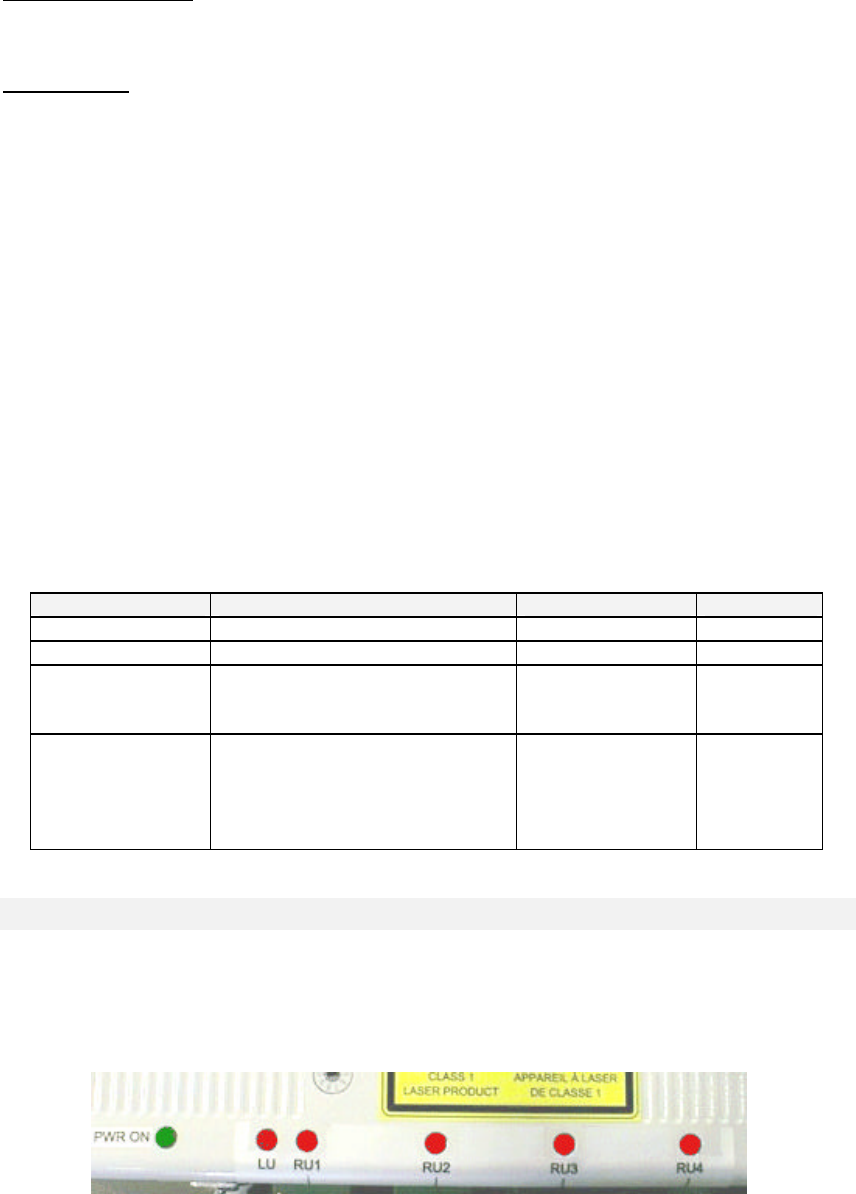
Local unit LEDs are fully managed by software according to different severity levels, and
reported as relay contact and visual alarms (LEDs). There are six LED’s on the Local unit.
Four are related to each optical link and remote unit, one is related to local unit, and one is for
power supply.
Figure 5 TFLF Local Unit Status LED’s
MN021-01
Page 11 of 28
The local unit has different monitor signals, leading to different alarms:
ALARM DESCRIPTION LED STATUS SEVERITY COLOR
UL AGC out of range RU1, 2, 3, or 4 Flashing MINOR Red
UL optical power too low RU1, 2, 3, or 4 Fixed MAJOR Red
DL laser optical power too low LU Fixed MAJOR Red
UL RF amplifier LU Fixed MAJOR Red
DL RF amplifier LU Fixed MAJOR Red
Temperature alarm LU Flashing MINOR Red
Supply alarm LU Fixed MAJOR Green
The Link LEDs (RU1, 2, 3, and 4) report information from the remote units, according to the
following table:
ALARM DESCRIPTION LED STATUS SEVERITY
DL AGC out of range RU1, 2, 3, or 4 Flashing MINOR
DL optical power too low RU1, 2, 3, or 4 Fixed MAJOR
DL RF amplifier 1 RU1, 2, 3, or 4 Fixed MAJOR
DL RF amplifier 2 RU1, 2, 3, or 4 Fixed MAJOR
Antenna disconnected (DC loop) RU1, 2, 3, or 4 Flashing MINOR
External 1 RU1, 2, 3, or 4 Fixed MAJOR
External 2 RU1, 2, 3, or 4 Fixed MAJOR
6.1. Alarm contacts
The TFLF provides dry contacts to report alarm condition to third party equipment auxiliary
inputs (i.e. BTS or repeater). The dry contacts status is reported in the following table:
ALARM CONDITION CONTACT POSITION
NONE OPEN
MINOR OPEN
MAJOR CLOSED
If the alarm condition is “none” (contact open) the relays driving the contacts are normally
excited. In case of power supply failure the system is not powered and the dry contacts will be
automatically driven to a “closed condition”, corresponding to a “major” alarm.
6.2. UL level setting
The TFLF is designed to be compatible with most pico/micro BTS’s. The allowed levels can
span from 10mW to 5W. Power levels greater than 100mW require an external attenuator. This
external attenuator will affect both the uplink and downlink paths, adding unwanted attenuation
to the uplink path.
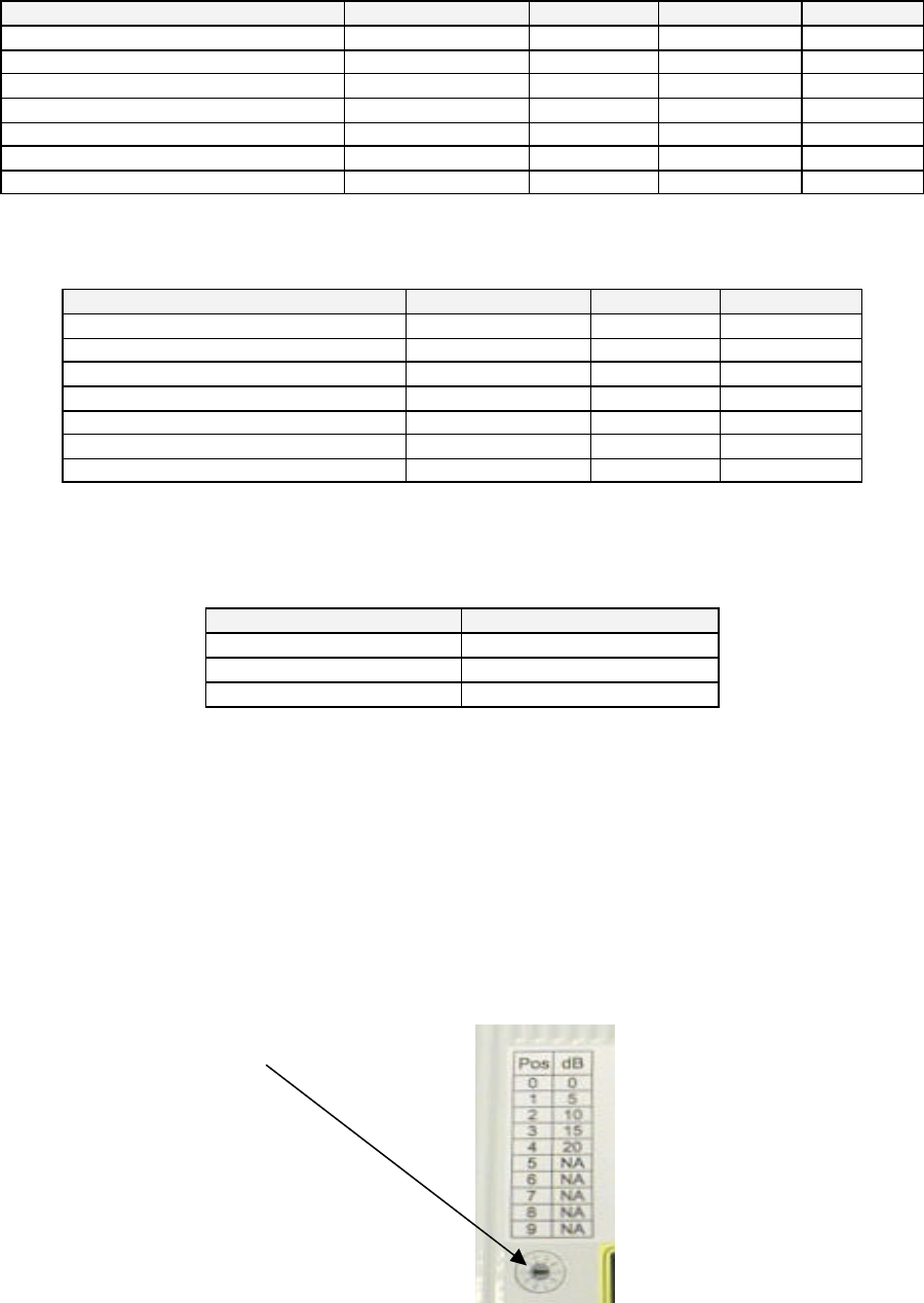
In this case, the variable uplink attenuator must be adjusted (the range is 20dB with 5dB steps),
as per table in the appendix E.
To adjust the value use a flat screwdriver
Figure 6 Uplink Attenuator Adjustment
6.3. Software auto-configuration
A simple procedure is required to set the final system configuration. This is necessary in case of
a partially populated system, where optical alarms can arise if some optical ports are not
connected to remote units. The procedure to be followed is reported below:
MN021-01
Page 12 of 28
STEP SET CONFIGURATION ACTION
1 Install your system properly, acco
rding to the required number of remote units,
and power up the system.
2 Wait until the communication between TFLF and TFAF’s are established and
the alarms relevant to UNUSED port arises (LU LED fixed).
3 Verify that all USED ports don’t have active alarms. In case, please follow the
troubleshooting steps to remove unwanted alarms.
4 Press the “store button” for at least 5 second.
5
All the TFLF LEDs will flash for 3 seconds, and the UNUSED port alarms will
disappear. All the alarms relevant to unused ports will be disabled.
6 Switch off the system, wait a few seconds, power up and verify the unwanted
alarms are masked.
A restore procedure is available to replace a wrong configuration and restore the initial
configuration:
STEP RESTORE CONFIGURATION ACTION
1 Power off the system while holding down the “store” button.
2 Power on the system.
3 The LED will flash for 2 seconds.
4 All of the active alarms will be displayed again.
7. Installation and Cabling
7.1. Power supply
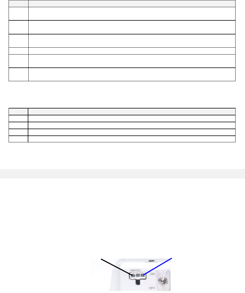
The system is designed to be powered by standard telecom voltage –48VDC. The power
consumption is 9W for the TFLF. The supply connector part name is MOLEX 5569-03. A
connectorized jumper is shipped with each Local unit.
ü WARNING: The system is connected POSITIVE to GROUND. Grounding connections must be carefully managed
in order to avoid reverse polarity mistakes
Figure 7 DC Power Connections for Local Unit TLFL
Blue negative –48VDC Black ground 0V
MN021-01
Page 13 of 28
7.2. RF Ports
The RF port is a duplexed N-female connector. See the tables in the Appendix to set the proper
input level.
ü WARNING: Do not exceed the maximum RF level allowed for downlink input. See appendix B - technical
specifications
Figure 8 RF Connector for Local Unit TLFL
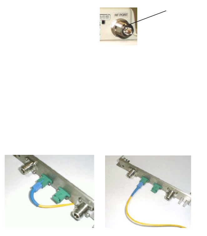
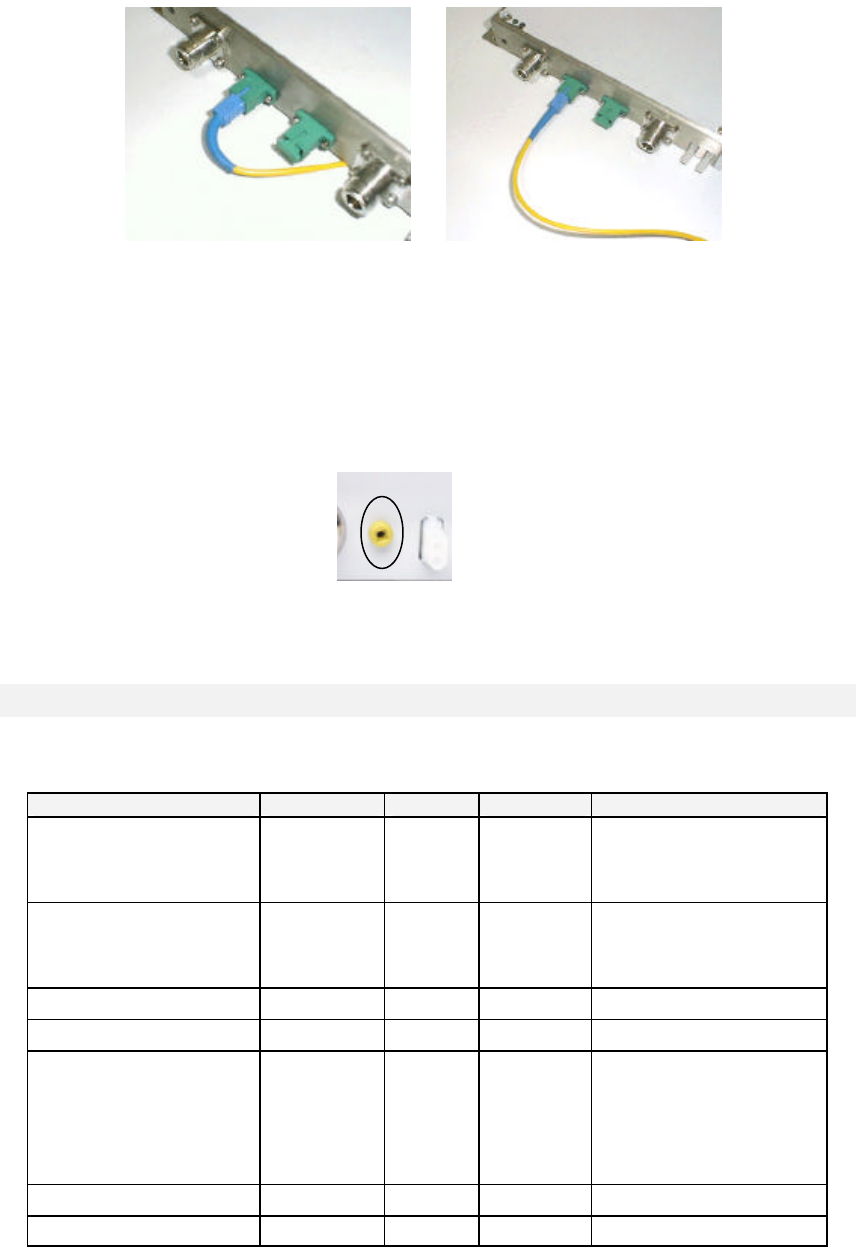
7.3. Optical fibres connection
Optical connectors need to have proper alignment and mechanical support. When inserting an
optical connector, take care to handle it carefully to avoid damage to the fibre. Remove the dust
cap only prior to making connections.
ü Do not force or stretch the fibre pigtail with curve radius less than 5 cm.
ü See Figure 9 for optimal fibre cabling.
Figure 9 Optical Fiber Connection Examples
WRONG OPTIMAL
N-female
connector

MN021-01
Page 14 of 28
8. Troubleshooting
ALARM DESCRIPTION LED STATUS SEVERITY ACTION
UL AGC out of range RU1, 2, 3, or 4 Flashing MINOR
Optical power below –4dBm:
check for fiber or splices
stresses, clean optical
connectors
UL optical power too low RU1, 2, 3, or 4 Fixed MAJOR
Low optical power below –6
dBm: check for fiber or splices
stresses, clean optical
connectors
If TFAF has faulty laser,
replace TFAF
DL laser optical power too low
LU Fixed MAJOR Laser failure: replace TFLF
UL RF amplifier LU Fixed MAJOR Internal failure: replace TFLF
DL RF amplifier LU Fixed MAJOR Internal failure: replace TFLF
Temperature alarm LU Flashing MINOR External temperature too high:
check air circulation
Supply alarm LU Fixed MAJOR Internal failure: replace TFLF
REMOTE UNIT ALARM DESCRIPTION
DL AGC out of range RU1, 2, 3, or 4 Flashing MINOR
Optical power below –4dBm:
check for fiber or splices
stresses, clean optical
connectors
DL optical power too low RU1, 2, 3, or 4 Fixed MAJOR
Optical power below –6dBm:
check for fiber or splices
stresses, clean optical
connectors
DL RF amplifier 1 RU1, 2, 3, or 4 Fixed MAJOR Internal failure: replace TFAF
DL RF amplifier 2 RU1, 2, 3, or 4 Fixed MAJOR Internal failure: replace TFAF
Antenna disconnected
(DC loop) RU1, 2, 3, or 4 Flashing MINOR
Antenna cable probably broken
or disconnected.
Antenna connected to TFAF
doesn’t support DC-loopà see
store procedure to mask
unwanted alarm
External 1 RU1, 2, 3, or 4 Fixed MAJOR External alarm 1
External 2 RU1, 2, 3, or 4 Fixed MAJOR External alarm 2
NOTE: All major alarms will trigger the dry contacts to “closed” status.
MN021-01
Page 15 of 28
TFAF remote unit
9. Part description
Figure 10 Remote Unit TFAF
Downlink Optical in
Uplink Optical out
Antenna port 1
Antenna port 2
Power supply input
–48VDC
External alarms 1&2
Optical power
Test point
Power: green led Alarm: red led
Fittings for
wall fixing
MN021-01
Page 16 of 28
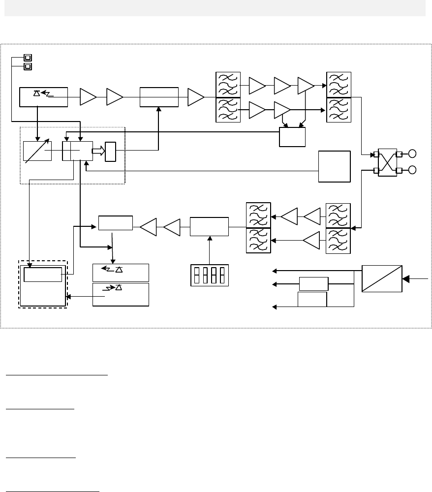
10. Functional description
10.1. Block diagram
Figure 11 Remote Unit TFAF Block Diagram
10.2. Up link operations
Low noise amplification: the low level signal coming from the antenna and duplexer is amplified
and filtered.
E/O Conversion: The RF signal modulates the intensity of an optical carrier through an electro-
optic device (laser).
10.3. Down link operations
O/E Conversion: The modulated optical signal coming from the local units is detected and
demodulated back to electrical signal.
Amplification & AGC: Variable amplification is needed to compensate for the variable optical
fibre loss, maintaining a good signal to noise ratio, to maintain a constant gain for each link. The
resultant signal is amplified, filtered and is duplexed to feed the antenna.
10.4. Remote supply
The remote unit is powered with –48VDC supply, positive to GROUND, by means of composite
copper wire and fibre cable.
10.5. Automatic Gain Control
Optical link losses are typically related to:
• Fibre length (0.2-0.4dB/Km @ 1300nm)
• Splices loss
• Optical connectors tolerances and aging
BriteCell™ Fast implements an automatic gain control (AGC) mechanism to maintain constant
RF link gain, regardless of the overall optical link losses. The allowed optical loss per link must
be in the range of 3dB. Losses outside this window will trigger alarms and warnings according
to the following table:
DC DC -48VDC
PHOTODETECTO
Downlink
AGC
VARIABLE
GAIN AMP.
D
A
C
A
DD
C µPROC.
Diff. AMP
LASER module
MONITOR PHOTODET.
LASER DIODE
VOLTAGE
CONTROLLED
ATTENUATOR
MATCHING
NETWORK
UL ATTENUATOR CONTROL
SWITCHES
attenuator
control
voltage
DL final amplifier stage
current monitor
RF
SMA
RF SMA
50 Ω
Data link
DC/DC
converter
Voltage
Regulator
RX optical power monitor
Shut down
control
CURRENT
GENERATOR
LASER control
module
+12 V
-8 V
+5 V
Auxilliary External
alarms
DC loop

MN021-01
Page 17 of 28
OPTICAL LOSS OPERATION ALARM SEVERITY
0 dB AGC working, constant RF gain none NONE
< 3dB AGC working, constant RF gain none NONE
< 5 dB AGC not working, RF gain
decreases according to 2dB
electrical per 1dB optical
AGC out of range:
red LED flashes MINOR
> 5 dB
AGC not working, the optical
signal is too low, the receiver is
automatically switched off in
order to reduce the unwanted
noise to the system.
Optical power too
low: red LED
fixed, relays
alarmed.
MAJOR
11. Alarms and settings
11.1. Remote unit LEDs
The TFAF is fully managed and supervised by the local microprocessor. The alarms are fully
managed by software according to different severity levels, and reported as local visual alarms
(LED’s) and on the data link to the local unit.
There are 2 LED on the Local unit, one red alarm LED is related to optical link and internal
failures, one green LED is for the power supply.
Figure 12 Remote Unit TFAF LED’s
REMOTE ALARM DESCRIPTION LED STATUS SEVERITY
UL AGC out of range RED Flashing MINOR
UL optical power too low RED Fixed MAJOR
DL RF amplifier 1 RED Fixed MAJOR
DL RF amplifier 2 RED Fixed MAJOR
Antenna disconnected (DC loop) RED Flashing MINOR
External 1 RED Fixed MAJOR
External 2 RED Fixed MAJOR
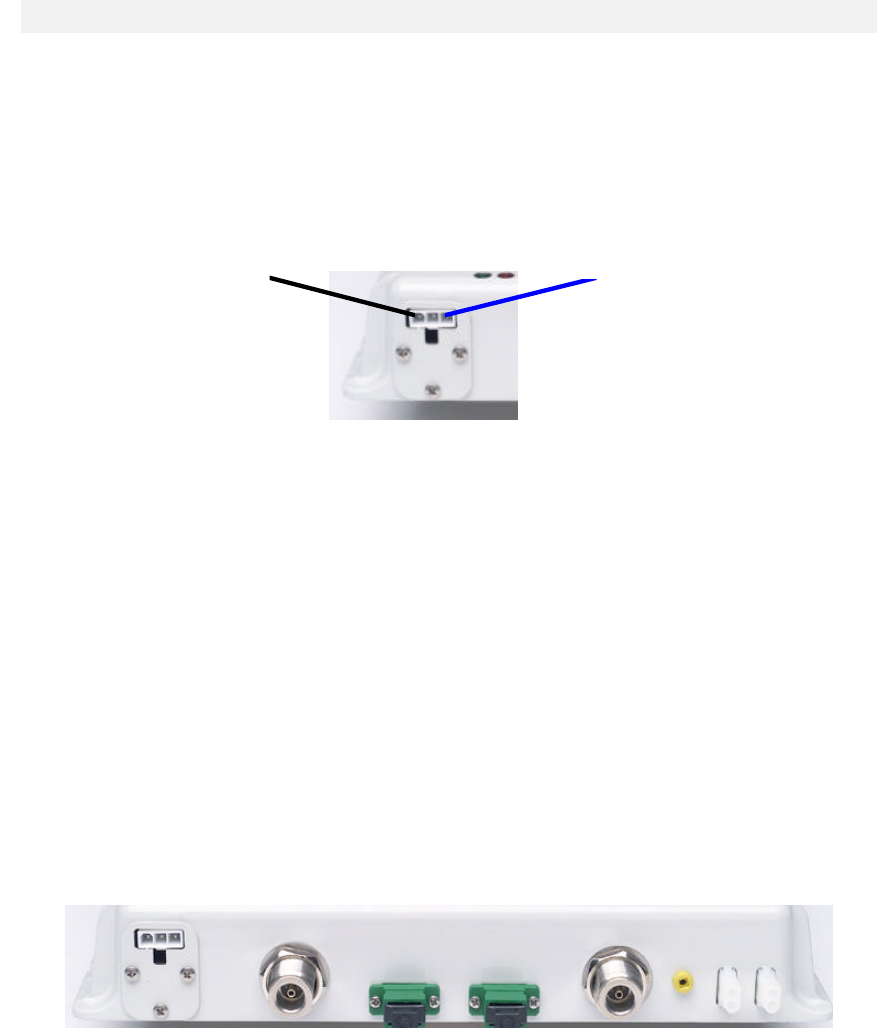
11.2. External alarms
Two external alarm contacts are provided. These contacts are open under non-alarm condition.
Figure 13 Remote Unit TFAF Alarm Connectors
MN021-01
Page 18 of 28
12. Installing and cabling
12.1. Power supply
The system is designed to be powered by standard telecom voltage –48VDC. The power
consumption is 12W for the TFAF. The supply connector part name is MOLEX 5569-03. A
connectorized jumper is shipped with each remote unit.
ü WARNING: The system is connected POSITIVE to GROUND. Grounding connections must be carefully managed
in order to avoid reverse polarity mistakes
Figure 14 DC Power Connections for Remote Unit TLAF
12.2. RF Ports
The RF port is a duplexed N-female connector. A DC loop mechanism is implemented to detect
a broken cable or a disconnected antenna. To perform this functionality a DC loop antenna
must be used. If the DC loop functionality cannot be used, follow the “store” procedure in the
TFLF to mask the DC loop alarm.
ü WARNING: If passive distribution is used after the remote unit, verify that passive splitters can be DC loop
enabled.
ü WARNING: Both RF ports are supplied with a DC current of 2mA(max) @5Volts.
Figure 15 Remote Unit TFAF RF Connectors
12.3. Optical fibres connection
Optical connectors need to have proper alignment and mechanical support. When inserting an
optical connector, take care to handle it carefully to avoid damage to the fibre. Remove the dust
cap only prior to making connections.
ü Do not force or stretch the fibre pigtail with curve radius less than 5 cm.
ü See Figure 16 for optimal fibre cabling.
Blue NEGATIVE –48VDC
Black GROUND 0V
MN021-01
Page 19 of 28
Figure 16 Optical Fiber Connection Examples
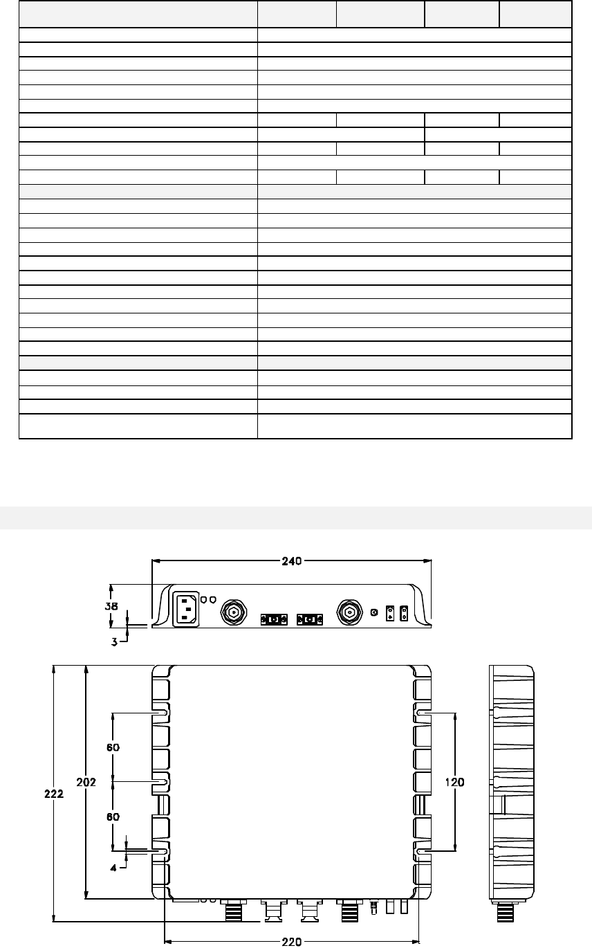
12.4. Test point
An electrical test point is available on the remote unit to check the downlink optical power.
Connect the fibre coming from the local unit, power both units and measure with a multimeter
the voltage between ground and the test point. A satisfactory DL optical power will give
measurement greater than 300mV, corresponding to an optical power level of around –5dBm.
Figure 17 Remote Unit TFAF Electrical Test Point
13. Troubleshooting
REMOTE UNIT ALARM Alarm LED STATUS SEVERITY ACTION
DL AGC out of range RED Flashing MINOR
Optical power below –4dBm:
check for fiber or splices
stresses, clean optical
connectors
DL optical power too low RED Fixed MAJOR
Optical power below –6dBm:
check for fiber or splices
stresses, clean optical
connectors
DL RF amplifier 1 RED Fixed MAJOR Internal failure: replace TFAF
DL RF amplifier 2 RED Fixed MAJOR Internal failure: replace TFAF
Antenna disconnected (DC
loop) RED Flashing MINOR
Antenna cable probably
broken or disconnected.
Antenna connected to TFAF
doesn’t support DC-loopà see
store procedure to mask
unwanted alarm
External 1 RED Fixed MAJOR External alarm 1
External 2 RED Fixed MAJOR External alarm 2
WRONG OPTIMAL

MN021-01
Page 20 of 28
SYSTEM INSTALLATION
14. Installation and cabling
BriteCell™ FAST is designed to be simple and easy to install and commission. It requires a
minimum number of tools and equipment. However, it is necessary to observe local regulations
when planning and implementing an RF system and safety conventions must be strictly adhered
to at all times. Particular attention should be paid to the presence of optical lasers, which can
represent the only potential hazard related to the use of BriteCell equipment. A working
knowledge of optics, and the safety procedures in their use, is required by the installation,
commissioning and maintenance staff.
14.1. Local unit location
TFLF local units should be placed as near as possible to the BTS or the RF repeater and should
be easily accessible as they provide visual alarm information for the system maintenance.
ü The position of the remote unit should be vertical to maximize thermal dissipation.
ü There should be easy access to the optical and RF cables.
14.2. Remote unit and antennas location
The most efficient locations for the TFAF remote transceivers will minimise the number of
antennas required, while maintaining the coverage level goal.
ü The position of the remote unit should be vertical to maximize thermal dissipation.
ü There should be easy access to the optical and RF cables.
The passive antenna’s placing should be chosen provide the maximum indoor radio coverage,
and should be mounted at a minimum height of 2.5m from the ground. They should not be
placed near trees, plants, metal grids or other obstacles, which could disturb their functionality
and lead to a degradation of the device's performance.
14.3. Power Supply
A BriteCell™ Fast system has been designed for remote power distribution, but is also possible
to supply each unit separately at –48VDC. A power supply may be distributed in a composite
cable, copper and fibre, or two separate parallel cables may be run. A suitable external adapter
to provide at least 100W at –48VDC must be used.
15. System start-up
To avoid damaging the equipment, the following criteria must be used to start up the system:
1. Verify all the power supply connections.
2. Verify all the RF connections and power levels at the BTS/Repeater interface.
3. Verify all the optical connections.
4. Switch on the system.
5. Check for alarm status and in case of alarm refer to troubleshooting paragraph.
16. Maintenance
It is a good rule, when working with the fibre optic components, to always dispose of the
appropriate screw covers for closure of the optic connectors that are not connected. The
intrinsic delicateness of an optic connection must be highlighted. A minimum layer of dust
causes a notable increase of the insertion loss, therefore:
ü Always close the optic connectors that are not connected with the appropriate screw covers.
ü Always use compressed gas to remove any deposits in the receptacles before closing them.
ü Use the appropriate cloths to clean the connectors.
ü Do not allow the male connector to come into contact with skin or oily surfaces.
ü Should it be necessary to clean the optic connector, only use pure alcohol.

MN021-01
Page 21 of 28
OTHER INFORMATION
17. Warranty conditions
Customer service is granted all over the world during and after the warranty period.
Allen Telecom warrants to the terms and conditions hereto set forth, all products manufactured
by it to be free under normal use and service from defects in materials and workmanship for a
period of one (1) year from the date of shipment to the first consumer (the “Warranty Period”).
The warranty applies only if the warranty period is not expired and the defect is imputable to the
product.
Our obligation under this Warranty is limited to prompt repair or replacement of the product,
without charge, when the product is returned to the factory.
The warranty shall not apply to any product which has been repaired or altered in any manner
or if the defect, malfunction or failure of the product was caused by damage by lightning, flood
or other acts of nature or by power surges, or from unreasonable use, or from improper
installation or application, or to any product which has not been maintained or used in
accordance with the operating specifications set forth in this manual.
Allen Telecom evaluates if the product can be repaired or if it is necessary to replace the unit.
In case the product is out of warranty, the customer will be informed about the cost for repairing
or replacing the unit. The service will be provided only after receiving Customer’s authorisation.
Before returning the goods, the customer should give prior notice to Allen Telecom through
normal return authorisation procedure. Allen Telecom aims to offer an excellent service. To
do that we ask our customer to enclose with the returned product an accompanying letter,
including the following information:
Company name
Address
Contact person
Invoice number
Delivery note
No. of pieces
Model*
Serial Number*
Lot*
Year*
Description of the
Failure/defect
* Refer to the serial label
Note: Each product must be packaged with care before shipment.
Allen Telecom will issue a check report, which is included in the packing together with the
product being returned. The customer will be informed about any corrective actions suggested
by quality assurance.

MN021-01
Page 22 of 28
18. Technical support
Our on-line help desk at www.tekmar.it gives immediate access to our team of Experts, who
are committed to providing you with the best service in the shortest possible time.
For further information on the product, not described in this publication, you can contact our
Project Implementation & technical support team at helpdesk@tekmar.it
APPENDIX
19. Appendix A : Installation checklist
The following checklist provides a summary of the procedures for installing a BriteCell™ Fast
system.
Step Item/ Action Description ♦♦
1 BriteCell™ Fast Site Drawing Master copy of the site plan noting the remote
locations and serial numbers, and the location of
the indoor coverage antenna(s). This should
characterize the design parameters for the
system including cable paths and lengths.
2 Equipment List: Quantity & serial numbers:
BriteCell™ Fast Donor
BriteCell™ Fast Remotes
AC Power Source
AC Power Outlet
Coverage Antenna(s)
Input coaxial cable
Coverage Antenna Cables
3 Installation tools:
Cable connector Tools* Crimper, knife, etc.
Multimeter To ensure no cable shorts.
Handset with Power Indicator To verify coverage after commissioning.
4 Run Cable Install Cable in the site.
5 Attach Connectors* Measure resistance across center pin and outer
shell (ground) to ensure no short.
7 Record Serial Numbers and
Locations on site Drawing. Note: this is to help Technical Support
Specialists, should you need their assistance.
8 Mount the Equipment Including indoor coverage antennas.
9 Connect the coaxial cables as
shown on the Site Plan Use caution when connecting semi-flexible
cables to the mounted BriteCell™ Fast and
antennas. Excessive force on antenna or
BriteCell™ Fast connectors will result in serious
equipment damage.
10 Supply AC Power, and
commission the System. Check the BriteCell™ Fast status LED’s.
11 Check Power Levels Check power indication of handheld mobile at
various locations within the coverage area.
* As Required

MN021-01
Page 23 of 28
20. Appendix B – Technical specifications
TTFFAAFF -- RREEMMOOTTEE UUNNIITT
Downlink
Optical receiver PIN photodiode
Max allowed input optical power < +3dBm
Allowed input optical power under AGC 0dBm ..-3dBm
Allowed optical input back reflection > -36dB
Optical input alarm threshold <-5dBm
Uplink
Optical transmitter Laser diode, class 3A (EN60825)
Wavelength 1310 ± 10nm
Output optical power -1dBm typ.
Max allowed RF input level -15dBm (1 tone CW)
RF interface
Operating frequency band See options & configurations table
RF ports 2
Connector N-f
Impedance 50 Ω
Return loss > 10 dB
Mechanical & environmental
Dimensions (mm) 240h x 200w x 36d
Weight 1.7 Kg max
Colour RAL 7035
Power supply (negative supply) -48VDC, 15W max
Alarms Major and minor led alarm (see manual)
Temperature range Operating:
Storage: 5 ÷ +40 °C
-20 ÷ +65 °C
MTBF >200.000 h @25°C
Compliance UL-94; ETS300 019-1-3, class 3.1; EN55022 class B - EN60950,
CE
TTFFLLFF -- LLOOCCAALL UUNNIITT
Downlink (1 section of 4)
Optical transmitter Laser diode, class 1 (EN60825)
Wavelength 1310 ± 10nm
Output optical power +0dBm typical
Max allowed RF input level +27dBm (1 tone CW)
Uplink(1 section of 4)
Optical receiver PIN photodiode
Max. allowed input optical power < +3dBm
Allowed input optical power under AGC -1dBm ÷-4dBm
Allowed optical input back reflection < -36dB
RF presettable gain reduction (PGR2) 0/5/10/15/20 dB
Optical input alarm threshold <-6dBm
RF interface
Operating frequency band See options & configurations table
Connector N-f
Impedance 50Ω
Return loss > 12dB
Mechanical & environmental
Dimensions (mm) 240h x 200w x 36d
Weight 1.7 Kg max
Colour RAL 7035
Power supply (negative supply)
-48VDC, 10W max
power consumption with 4 TFAF (remote supply) < 80W
Temperature range Operating:
Storage: 5 ÷ +40 °C
-20 ÷ +65 °C
Alarms Local led alarm (major or minor)
Remote and optical link led alarm (major or minor) (see manual)
Dry-contact major alarm
Compliance UL-94; ETS300 019-1-3, class 3.1; EN 60950
MN021-01
Page 24 of 28
RRFF SSYYSSTTEEMM PPEERRFFOORRMMAANNCCEE TTFFLLFF++11 ooff 44 TTFFAAFF ((11 ooff 22 TTFFAAFF RRFF ppoorrttss))
Downlink GSM
(900MHz) AMPS/Trunking
(800MHz) DCS
(1800MHz) PCS
(1900MHz)
Frequency translation None
Nominal RF input level +13dBm (1 tone CW)
Max allowed RF input level +27dBm (1 tone CW)
Nominal RF gain 0dB
Flatness (in passband) ±2dB
Output wideband noise <-120dBm/Hz
Max RF output level under ALC (note1) +13 dBm typ. +18 dBm typ. +13dBm typ. +17dBm typ.
Output 1dB compression point >+22dBm >+20dBm
Output spurious and intermodulations <-36dBm <-13dBm <-30dBm <-13dBm
RF output power per carrier see attached table
Output third order intercept point OIP3 >+33dBm >+33dBm >+30dBm >+30dBm
Uplink
Frequency translation None
Nominal RF gain (note 2) +12 dB
Flatness (in passband) ± 2 dB
RF presettable gain reduction (PRG note3) PRG2: 0/5/10/15/20 dB
Noise figure 13 dB typ.
Input third order intercept point IIP3 0dBm typ.
Blocking at 3 dB C/N degradation >-18dBm
Spurious free dynamic range (BW=25KHz) 78dB typ.
Spurious free dynamic range (BW=30KHz) 77dB typ.
Spurious free dynamic range (BW=200KHz) 72dB typ.
Spurious free dynamic range (BW=1230KHz) 67dB typ.
Fibre optic link
Fibre optic type Single mode, 9.5/125um
Max allowed optical fibre length < 1.5km
Max allowed optical budget for AGC operation 3 dB (optical)
Max. propagation delay including 1km single
mode fibre <5,2µs
Note 1: Measured with 1 CW tone
Note 2: with PRG1 and PRG2 set to 0
Note 3: PRG2 is on TFLF unit and it could be used for different BTS: (see manual)
21. Appendix C – Mechanical outline

MN021-01
Page 25 of 28
22. Appendix D – Power levels
Typical Output levels (dBm) at each TFA RF port versus different modulation scheme.
(NB: system gain is 0db, therefore the following values correspond also to min input levels)
Carriers CW GSM
900 GSM
1800 CDMA
800 CDMA
1800 Analog IDEN TDMA
800 TDMA
1900
1 +13.0 +19.0 +19.0 +15.5 +14.5 +19.0 +11.0 +19.0 +18.0
2 +10.0 +10.0 +10.0 +10.0 +10.0 +14.0 +8.0 +14.0 +13.0
3 +7.7 +7.7 +7.7 +5.0 +5.0 +12.0 +6.0 +12.0 +11.0
4 +6.7 +6.7 +6.7 +3.5 +3.5 +11.0 +4.5 +11.0 +10.0
23. Appendix E – Using external attenuator
The uplink step attenuator must be set to optimise the system performance dependent upon the
power into the BriteCell Fast TFLF local unit. The following table gives some examples:
Input Power External
Attenuation TFLF Attenuation
setting Uplink Gain
(TFAF+TFLF) Downlink Gain
+37dBm 20 dB (5W) 0 dB +12 dB -20 dB
+33dBm 20 dB (2W) 0 dB +12 dB -20 dB
+24dBm 10 dB 10 dB +2 dB -10 dB
+20dBm 5 dB 5 dB -3 dB -5 dB
+14dBm 0 dB 20 dB -8 dB 0 dB
+13dBm 0 dB 20 dB -8 dB 0 dB
24. Appendix F – System Design Guidelines
24.1. Introduction
This Appendix is intended to describe the guidelines for the design development of the
BriteCell/BriteCell Fast System.
24.2. Project Definition
In order to allow the design development, it’s important to collect the right information. The input
parameters needed for the BriteCell coverage design are:
1. The type of standard: (GSM, CDMA, DCS, …);
2. The frequency: needed in order to choose the proper equipment and to evaluate the
path loss;
3. The number of carriers: important to define the input/output level of the equipment;
4. The BTS type: the link between BTSs and BriteCell coverage system can be Direct
Connection or Radio Connection, so it’s important to know which of these configuration
is used. The type of BTS is needed in order to properly set up the UL and DL variable
attenuators;
5. Definition of the coverage area based on the map: to define the number of radiating
points and their location, it’s important to consider:
- The kind of walls and floors
- The presence of false ceiling
- Eventual obstacles (architectural or furnishing)
- The required minimum receive level for mobile
- The power supply
MN021-01
Page 26 of 28
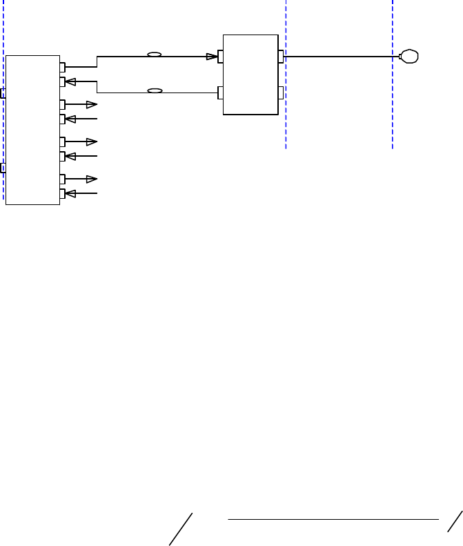
24.3. Antennas Positioning
Starting with the parameters determined as defined above, the number of radiating points can
be defined. The calculations needed can be implemented in a tool. The number of carriers is
used to define the TFA/TFAF RF Output Power (POUT TFA in
Figure 18) according to the table in Appendix C. As a rule of thumb, the power values for a
double number of carriers is obtained reducing the Power value of 3dB.
Figure 18 Diagram for Power Calculations
According to line-of-sight conditions, the calculation of the maximum coverage distance is
performed using the Free-space propagation formula. This formula is adapted to propagation in
indoor environments introducing an appropriate propagation index and including margin against
fading.
24.3.1. EIRP calculation:
][_][][][ ][ dBCableRFdBSplitterdBiyDirectivitdBmTFAFOUTdBm AAGPEIRP −−+=
where;
POUT TFAF = Remote Unit RF connector Output Power;
GDirectivity = Directivity Gain of the Antenna;
ASplitter = Splitter Insertion loss;
ARF_Cable = RF Cable Loss.
24.3.2. Max Coverage Distance Calculation:
PL
dBmRxdBWallsdBdBm
Exp
PAMFEIRP
m
mto_Prx_min
DistanceMax 1
10
][
][ )10(
4
_
]min[_][][][ −−−
⋅=
π
λ
wher
e;
MF = Margin against Fading;
AWalls = Walls supplementary Attenuation;
PRx-min = Minimum Required Power Level;
ExpPL = Path Loss Exponent (propagation index);
λ
= Wavelength.
The results can detailed for different Remote Unit configuration (splitter insertion loss, RF cable
length, additional attenuation e.g. walls).
ü Depending on the number of RF carriers, the antenna type and the RF cables type, the maximum distance that the
system is able to perform is estimated. This calculation is used to plan antenna positioning so that the project
requirement (Minimum Down Link Power Level) is met.
ü Technical Suggestion: The design is an iteration process so it’s advisable to start from the hypothesis that the
Cable Loss and the Antenna Gain compensate each other and consequently the EIRP is equal to the TFA Output
Power. To reach a good coverage, a target is to choose the antenna positioning in order to maximize Line of Sight.
TFA
Fiber
Remote
Unit
TFAF
Fiber
Remote
Unit
TFLF
Fiber
Donor
Unit
POUT TFAF
RF Cable
Loss
Antenna
Gain
PIN TFLF

MN021-01
Page 27 of 28
25. Appendix G - Classifying hazardous areas
Hazardous Area
A hazardous area is defined as: "An area in which a flammable substance in the form of gas or
vapour or dust, when mixed with air, is present in such proportions that it can explode when in
contact with an ignition source.
Area Classification
Hazardous areas are classified with respect to the potential danger or an explosion, and the
areas are divided into zones:
CONDITIONS CE Code EC
Continuously Hazardous Division 1 Zone 0 - An area in which an explosive ga
s/air mixture is
continuously present or is present for long periods.
Periodically Hazardous Division 1 Zone 1 -
An area in which an explosive gas/air mixture is
likely to occur under normal operating conditions.
Occasionally Hazardous Division 2 Zone 2 -
An area in which an explosive gas/air mixture is
unlikely to occur, but if it occurs, it will be of short duration.
Gases & vapour classification
Gases are grouped together basing on the amount of energy required to ignite the most
explosive mixture of the gases with air. Equipment is classified into groups according to the
gases and vapours for which it is suitable and must be selected with a grouping, which covers
the gases and vapours which, will be present where it is to be installed:
Group Representative Gas Ignition Energy
I
IIA
IIB
IIC
Methane
Propane
Ethylene
Hydrogen
320 Microjoules
300 Microjoules
160 Microjoules
40 Microjoules
GAS CE CODE IEC
Acetylene Class I, Group A Group IIC
Hydrogen, Butadiene, Ethylene Oxide, Propylene Oxide, or Acrolein Class I, Group B Group IIC
Ethylene, Cyclopropane, Ethyl Ether, or Ethylene Class I, Group C Group IIB
Propane, Acetone, Alcohol, Ammonia, Benzine, Benzol, Butane,
Gasoline, Hexane, Laquer Solvent vapours, Naptha, Natural Gas Class I, Group D Group IIA
Coal Mines Gaseous Mines Group 1
Combustible Dusts Class II
Ignitable Fibres or Flying Class III
To ensure the suitability of electrical equipment for use in hazardous areas, the equipment is
certified and uses various techniques known as Methods of Protection. As not all Methods of
Protection are suitable for all hazardous areas, care must be taken to select equipment, which
is suitable for use in the Zone in which it is installed.
Zone 0 Zone 1 Zone 2
Ex ia - Intrinsic safety
Ex s - Special protection if
specifically certified for Zone 0
Method suitable for Zone 0
Ex ib - Intrinsic Safety
Ex d - Flameproof enclosure
Ex e - Increased safety
Ex m - Encapsulation
Ex s - Special protection
Method suitable for Zone 0 or l
Ex N - Type of protection N
Ex o - Oil immersion*
Ex q - Powder filling*
Ex p - Pressurised or purging
* may be suitable for Zone 1
BriteCell Fast is designed and manufactured by
Tekmar Sistemi Srl
www.tekmar.it
Copyright Tekmar Sistemi s.r.l.
This document contains information, which is the property of Tekmar Sistemi S.r.l.
The contents are confidential, any reproduction of all or part of this publication, without the written consent
by Tekmar Sistemi s.r.l is forbidden.
This publication is issued to provide outline information and is not deemed to form any part of any offer
and contract. The company has a policy of continuous product development and improvement and we
therefore reserve the right to vary any information quoted without prior notice.