Andrew Wireless Innovations Group IONEUAP ION-E User Manual User s Manual for ION E
Andrew Wireless Innovations Group ION-E User s Manual for ION E
UserManual.wiki
>
Andrew Wireless Innovations Group
>
IONEUAP User Manual
>
user manaul
Contents
1.
user manaul
2.
user manual
3.
User Manual
user manaul
Navigation menu
Upload a User Manual
Namespaces
Wiki Guide
HTML
PDF
Info
Views
User Manual
Discussion / Help
Navigation

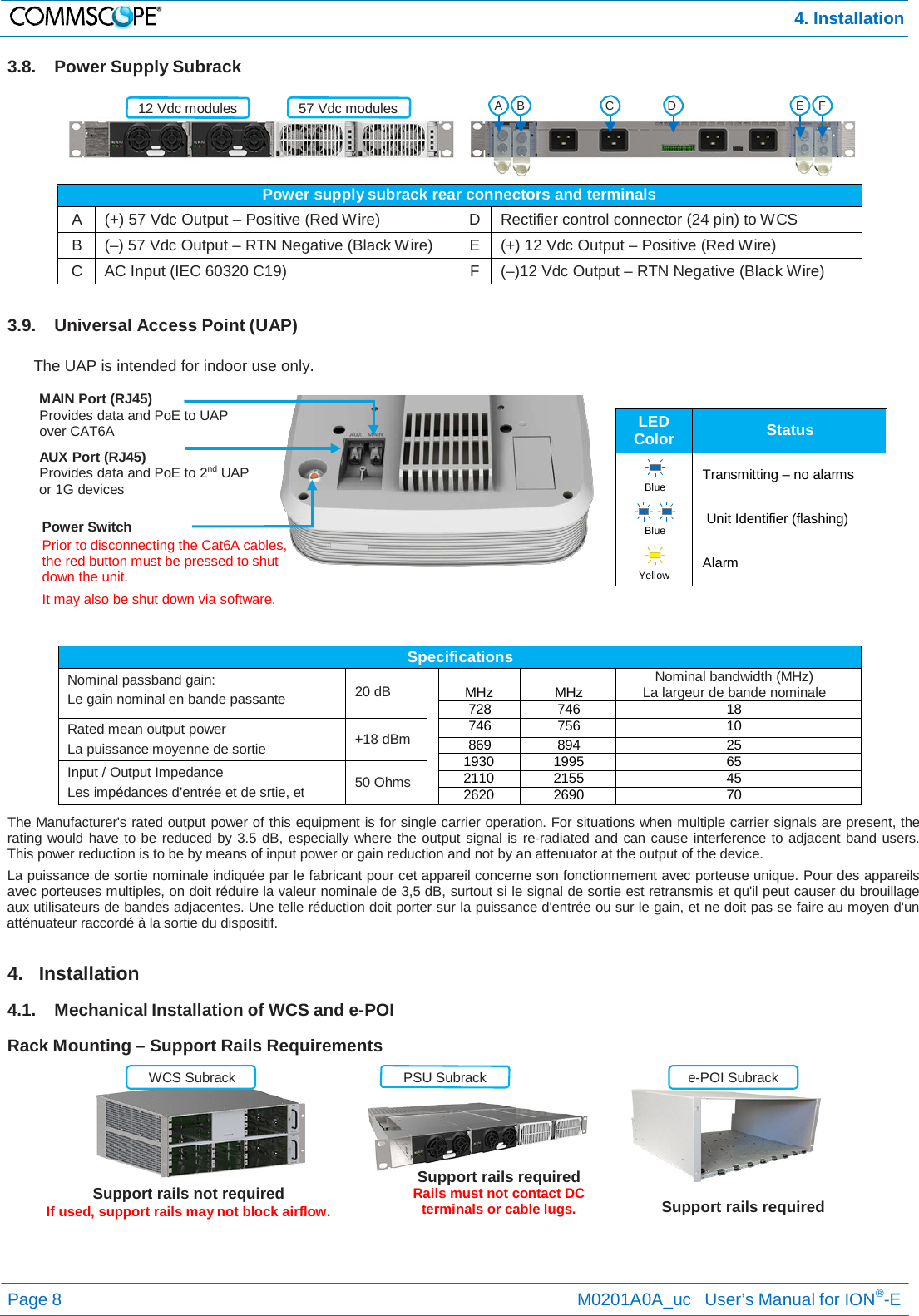
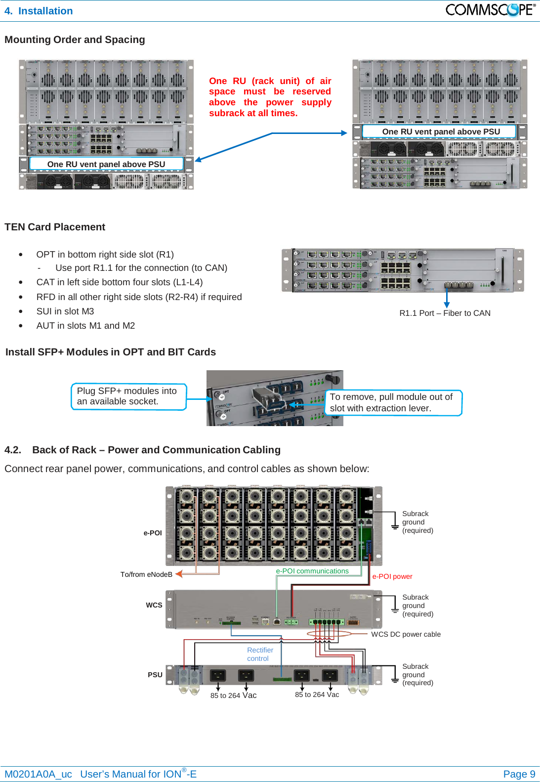
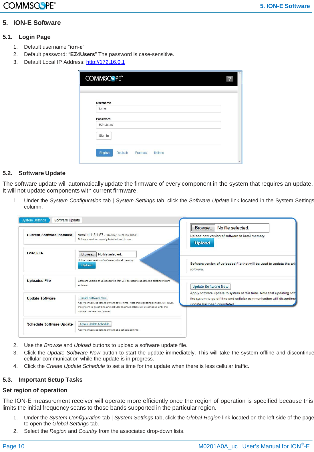
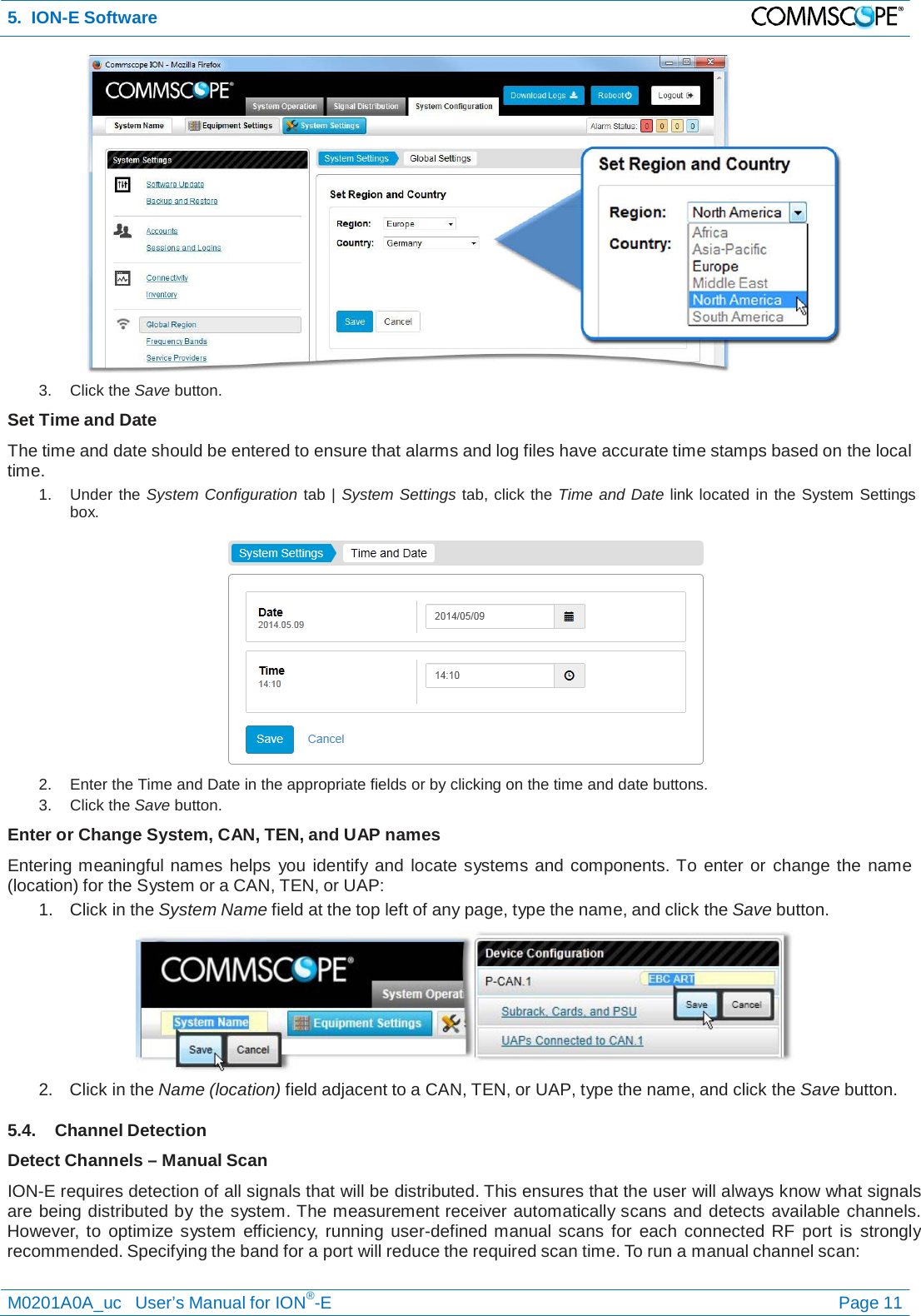
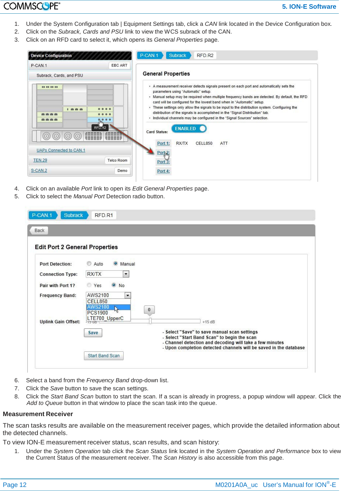
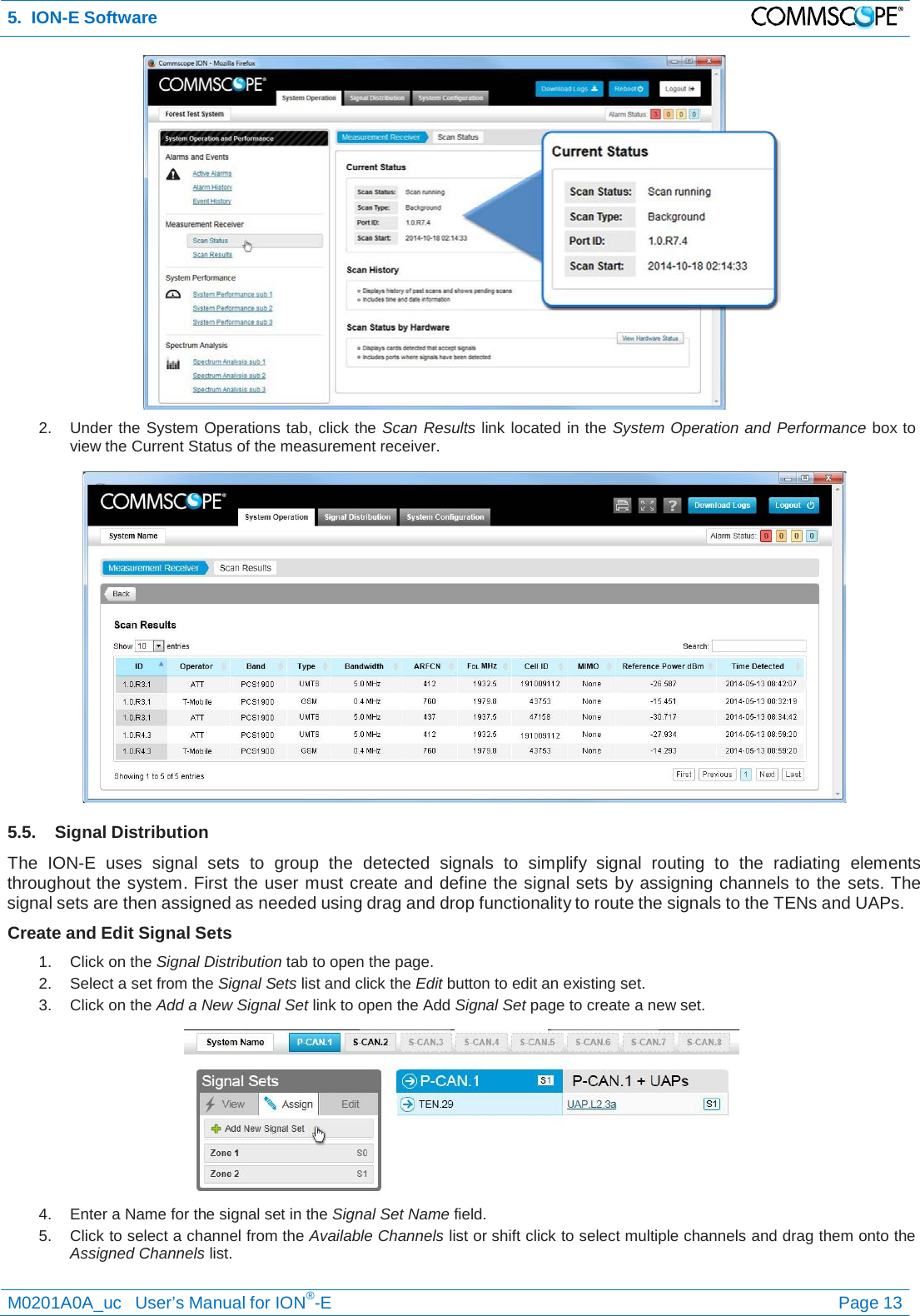
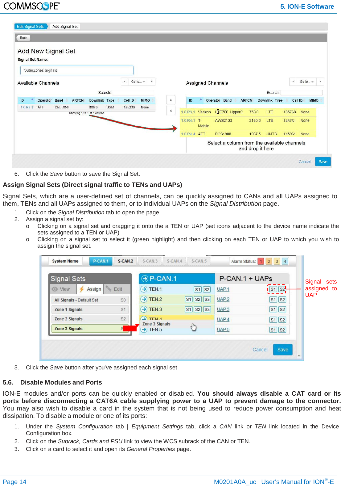
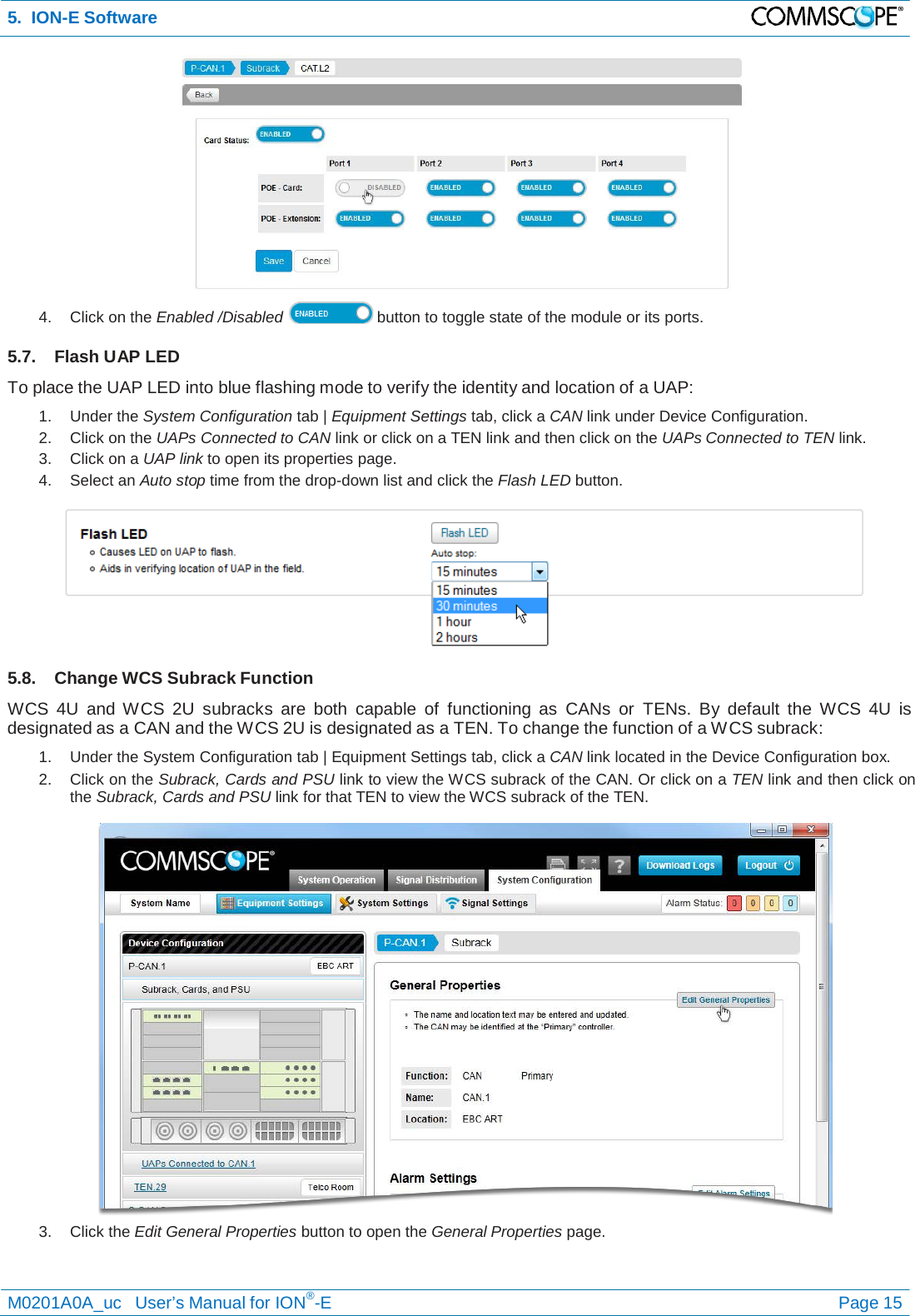
![1. General 1.3. Health and Safety 1. Warning: A High leakage current ground (earth) connection to the power supply subrack is essential before connecting the supply. 2. Caution: Laser radiation. Risk of eye injury in operation. Do not stare into the beam; do not view it directly or with optical instruments. 3. Caution: High frequency radiation in operation. Risk of health hazards associated with radiation from the antenna(s) connected to the unit. Implement prevention measures to avoid the possibility of close proximity to the antenna(s) while in operation. 1.4. Property Damage Warnings 1. Attention: Due to power dissipation, the power supply units may reach a very high temperature if not properly ventilated. Do not operate this equipment on or close to flammable materials. 2. Notice: ESD precautions must be observed. Before commencing maintenance work, use the available grounding (earthing) system to connect ESD protection measures. 3. Notice: Keep operating instructions within easy reach and make them available to all users. 4. Notice: Only license holders for the respective frequency range are allowed to operate this unit. 5. Notice: Read and obey all the warning labels attached to the unit. Make sure that all warning labels are kept in a legible condition. Replace any missing or damaged labels. 6. Notice: Make sure the unit’s settings are correct for the intended use (refer to the manufacturer product information) and regulatory requirements are met. Do not carry out any modifications or fit any spare parts, which are not sold or recommended by the manufacturer. 1.5. Compliance 1. Warning! This is class A equipment. This equipment can cause radio interference in domestic areas. In this case the operator can be asked to start preventive action. 2. Notice: For installations, which have to comply with FCC RF exposure requirements, the antenna selection and installation must be completed in a way to ensure compliance with those FCC requirements. Depending on the RF frequency, rated output power, antenna gain, and the loss between the repeater and antenna, the minimum distance D to be maintained between the antenna location and human beings is calculated according to this formula: 3. Notice: For installations which have to comply with European EN50385 exposure compliance requirements, the following Power Density limits/guidelines (W/M²) according to ICNIRP are valid: a. 2 for frequencies from 10 MHz to 400 MHz b. F (MHz) / 2000 for frequencies from 400 MHz to 2 GHz c. 10 for frequencies from 2 GHz to 300 GHz 4. Notice: Notice: For installations which have to comply with FCC/Industry Canada requirements: English This device complies with FCC Part 15. Operation is subject to the following two conditions: (1) this device may not cause interference, and (2) this device must accept any interference, including interference that may cause undesired operation of the device. This device complies with Health Canada’s Safety Code. The installer of this device should ensure that RF radiation is not emitted in excess of the Health Canada’s requirement. Information can be obtained at http: //www.hc-sc.gc.ca/ewh-semt/pubs/radiation/radio_guide- lignes_direct-eng.php. Changes or modifications not expressly approved by the party responsible for compliance could void the user’s authority to operate the equipment. The antenna(s) used for this transmitter must be installed to provide a separation distance of at least 20 cm from all persons and must not be co-located or operating in conjunction with any other antenna or transmitter. French Cet appareil est conforme à FCC Partie15. Son utilisation est soumise à Les deux conditions suivantes: (1) cet appareil ne peut pas provoquer d’interférences et (2) cet appareil doit accepter Toute interférence, y compris les interférences qui peuvent causer un mauvais fonctionnement du dispositif. Cet appareil est conforme avec Santé Canada Code de sécurité 6. Le programme d’installation de cet appareil doit s’assurer que les rayonnements RF n’est pas émis au-delà de I’exigence de Santé Canada. Les informations peuvent être obtenues: http://www.hc-sc.gc.ca/ewh- semt/pubs/radiation/radio_guide-lignes_direct-fra.php Les changements ou modifications non expressément approuvés par la partie responsable de la conformité D[ cm] = where P[ mW ] 4 ∗π ∗ PD 2 [ mW / cm ] pourraient annuler l'autorité de l'utilisateur à utiliser cet équipement. La ou les antennes utilisées avec cet émetteur doivent être installées avec une séparation d’au minimum 20cm avec • P (mW) is the radiated power at the antenna, i.e. the max. rated repeater output power in addition to the antenna gain minus the loss between the repeater and the antenna. a. PD (mW/cm²) is the allowed Power Density limit acc. to 47 CFR 1.1310 (B) for general population / uncontrolled exposures which is o F (MHz) / 1500 for frequencies from 300MHz to 1500MHz o 1 for frequencies from 1500MHz to 100,000MHz RF exposure compliance may need to be addressed at the time of licensing, as required by the responsible FCC Bureau(s), including antenna co-location requirements of 1.1307(b)(3). toute personne et ne doivent pas être co-localisées ou utilisées avec toute autre antenne ou tout autre émetteur. 5. Notice: Corresponding local particularities and regulations must be observed. For national deviations, please refer to the respective documents included in the manual CD that is delivered with the unit. M0201A0A_uc User’s Manual for ION®-E Page 3](https://usermanual.wiki/Andrew-Wireless-Innovations-Group/IONEUAP.user-manaul/User-Guide-2552804-Page-3.png)