Andrew Wireless Innovations Group IONEUAP ION-E User Manual User s Manual for ION E
Andrew Wireless Innovations Group ION-E User s Manual for ION E
Contents
- 1. user manaul
- 2. user manual
- 3. User Manual
user manaul
ION
®
-E
Series
PRELIMINARY
User's Manual
M0201A0A
DISCLAIMER:
This document has been developed by CommScope, and is intended for the use of its customers and customer
support personnel. The information in this document is subject to change without notice. While every effort has been
made to eliminate errors, CommScope disclaims liability for any difficulties arising from the interpretation of the
information contained herein. The information contained herein does not claim to cover all details or variations in
equipment, nor to provide for every possible incident to be met in connection with installation, operation, or
maintenance. This document describes the performance of the product under the defined operational conditions and
does not cover the performance under adverse or disturbed conditions. Should further information be desired, or
should particular problems arise which are not covered sufficiently for the purchaser’s purposes, contact CommScope.
CommScope reserves the right to change all hardware and software characteristics without notice.
COPYRIGHT:
© Copyright 2014 CommScope Inc. All Rights Reserved.
This document is protected by copyright. No part of this document may be reproduced, stored in a retrieval system, or
transmitted, in any form or by any means, electronic, mechanical photocopying, recording, or otherwise without the
prior written permission of CommScope.
For patents see www.cs-pat.com.
TRADEMARKS
All trademarks identified by ® or ™ are registered trademarks or trademarks, respectively, of CommScope. Names of
products mentioned herein are used for identification purposes only and may be trademarks and / or registered
trademarks of their respective companies.
Andrew Wireless Systems GmbH, 09-February-2015
1. General
1.1. DCCS Technical Support
For technical assistance and support, please contact the DCCS technical support team.
Email: wisupport@commscope.com
+1 888-297-6433 in North and South America and +49 9099-69-333 in Europe, Middle East and Asia
1.2. Equipment Symbols Used / Compliance
Please observe the meanings of the following symbols used in this equipment:
Symbol Compliance Meaning
--- FCC
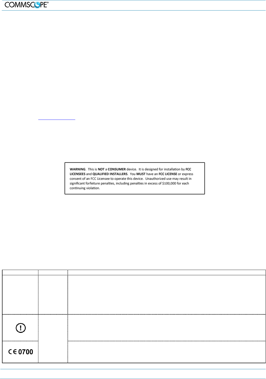
WARNING: This is NOT a CONSUMER device. It is designed for installation by FCC LICENSEES and
QUALIFIED INSTALLERS. You MUST have an FCC LICENSE or express consent of an FCC Licensee to
operate this device. Unauthorized use may result in significant forfeiture penalties, including penalties in
excess of $100,000 for each continuing violation.
You MUST register Class B signal boosters (as defined in 47 CFR 90.219) online at www.fcc.gov/signal-
boosters/registration.
Alert sign to R&TTE
To be sold exclusively to mobile operators or authorized installers – no harmonised frequency bands,
operation requires license
CE Intended use: EU and EFTA countries
Indicates conformity with the R&TTE directive 1999/5/EC certified by the notified body no. 0700.
M0201A0A_uc User’s Manual for ION®-E
Page 2
1.
General
1.3. Health and Safety
1. Warning: A High leakage current ground (earth) connection
to the power supply subrack is essential before connecting
the supply.
2. Caution: Laser radiation. Risk of eye injury in operation. Do
not stare into the beam; do not view it directly or with optical
instruments.
3. Caution: High frequency radiation in operation. Risk of
health hazards associated with radiation from the antenna(s)
connected to the unit. Implement prevention measures to
avoid the possibility of close proximity to the antenna(s)
while in operation.
1.4. Property Damage Warnings
1. Attention: Due to power dissipation, the power supply units
may reach a very high temperature if not properly ventilated.
Do not operate this equipment on or close to flammable
materials.
2. Notice: ESD precautions must be observed. Before
commencing maintenance work, use the available grounding
(earthing) system to connect ESD protection measures.
3. Notice: Keep operating instructions within easy reach and
make them available to all users.
4. Notice: Only license holders for the respective frequency
range are allowed to operate this unit.
5. Notice: Read and obey all the warning labels attached to
the unit. Make sure that all warning labels are kept in a
legible condition. Replace any missing or damaged labels.
6. Notice: Make sure the unit’s settings are correct for the
intended use (refer to the manufacturer product information)
and regulatory requirements are met. Do not carry out any
modifications or fit any spare parts, which are not sold or
recommended by the manufacturer.
1.5. Compliance
1. Warning! This is class A equipment. This equipment can
cause radio interference in domestic areas. In this case the
operator can be asked to start preventive action.
2. Notice: For installations, which have to comply with FCC RF
exposure requirements, the antenna selection and
installation must be completed in a way to ensure
compliance with those FCC requirements. Depending on the
RF frequency, rated output power, antenna gain, and the
loss between the repeater and antenna, the minimum
distance D to be maintained between the antenna location
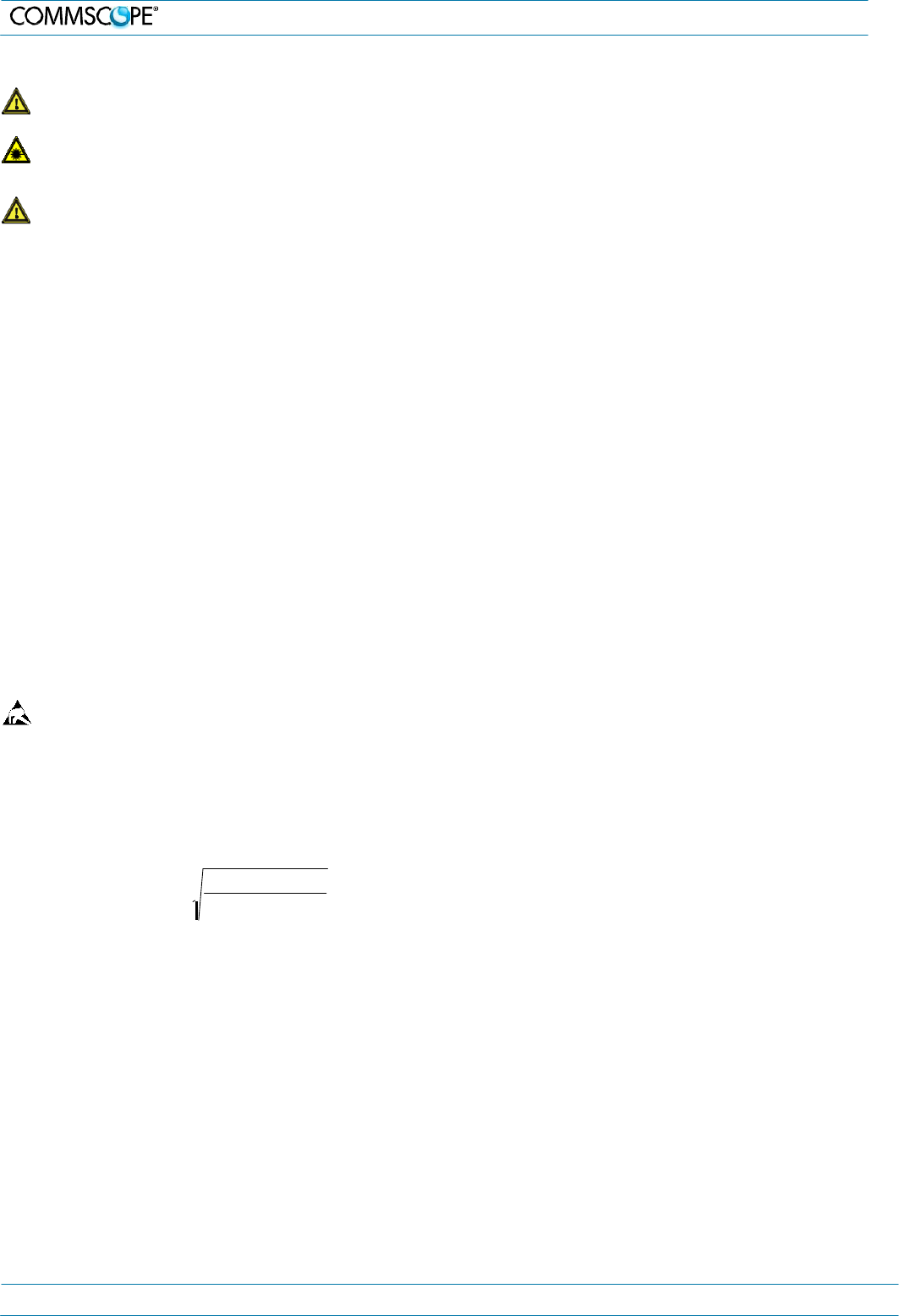
and human beings is calculated according to this formula:
3. Notice: For installations which have to comply with
European EN50385 exposure compliance requirements, the
following Power Density limits/guidelines (W/M²) according
to ICNIRP are valid:
a. 2 for frequencies from 10 MHz to 400 MHz
b. F (MHz) / 2000 for frequencies from 400 MHz to 2 GHz
c. 10 for frequencies from 2 GHz to 300 GHz
4. Notice: Notice: For installations which have to comply with
FCC/Industry Canada requirements:
English
This device complies with FCC Part 15. Operation is subject
to the following two conditions: (1) this device may not cause
interference, and (2) this device must accept any
interference, including interference that may cause
undesired operation of the device.
This device complies with Health Canada’s Safety Code.
The installer of this device should ensure that RF radiation is
not emitted in excess of the Health Canada’s requirement.
Information can be obtained at http:
//www.hc-sc.gc.ca/ewh-semt/pubs/radiation/radio_guide-
lignes_direct-eng.php.
Changes or modifications not expressly approved by the
party responsible for compliance could void the user’s
authority to operate the equipment.
The antenna(s) used for this transmitter must be installed to
provide a separation distance of at least 20 cm from all
persons and must not be co-located or operating in
conjunction with any other antenna or transmitter.
French
Cet appareil est conforme à FCC Partie15. Son utilisation
est soumise à Les deux conditions suivantes: (1) cet
appareil ne peut pas provoquer d’interférences et (2) cet
appareil doit accepter Toute interférence, y compris les
interférences qui peuvent causer un mauvais
fonctionnement du dispositif.
Cet appareil est conforme avec Santé Canada Code de
sécurité 6. Le programme d’installation de cet appareil doit
s’assurer que les rayonnements RF n’est pas émis au-delà
de I’exigence de Santé Canada. Les informations peuvent
être obtenues:
http://www.hc-sc.gc.ca/ewh-
semt/pubs/radiation/radio_guide-lignes_direct-fra.php
Les changements ou modifications non expressément
approuvés par la partie responsable de la conformité
D
[
cm]
=
where
P
[ mW
]
4
∗
π
∗
PD
2
[
mW / cm
]
pourraient annuler l'autorité de l'utilisateur à utiliser cet
équipement.
La ou les antennes utilisées avec cet émetteur doivent être
installées avec une séparation d’au minimum 20cm avec
• P (mW) is the radiated power at the antenna, i.e. the
max. rated repeater output power in addition to the
antenna gain minus the loss between the repeater and
the antenna.
a. PD (mW/cm²) is the allowed Power Density limit acc.
to 47 CFR 1.1310 (B) for general population /
uncontrolled exposures which is
o F (MHz) / 1500 for frequencies from 300MHz to
1500MHz
o 1 for frequencies from 1500MHz to 100,000MHz
RF exposure compliance may need to be addressed at the
time of licensing, as required by the responsible FCC
Bureau(s), including antenna co-location requirements of
1.1307(b)(3).
toute personne et ne doivent pas être co-localisées ou
utilisées avec toute autre antenne ou tout autre émetteur.
5. Notice: Corresponding local particularities and regulations
must be observed. For national deviations, please refer to
the respective documents included in the manual CD that is
delivered with the unit.
M0201A0A_uc User’s Manual for ION®-E Page 3
2. ION-E System
Overview
6. Note: For a Class A digital device or peripheral:
This equipment has been tested and found to comply with
the limits for a Class A digital device, pursuant to EN55022
and part 15 of the FCC Rules. These limits are designed to
provide reasonable protection against harmful interference
when the equipment is operated in a commercial
environment.
This equipment generates, uses, and can radiate radio
frequency energy and, if not installed and used in
accordance with the instruction manual, may cause harmful
interference to radio communications. Operation of this
equipment in a residential area is likely to cause harmful
interference in which case the user will be required to
correct the interference at his own expense.
7. Note: This unit complies with European standard EN60950.
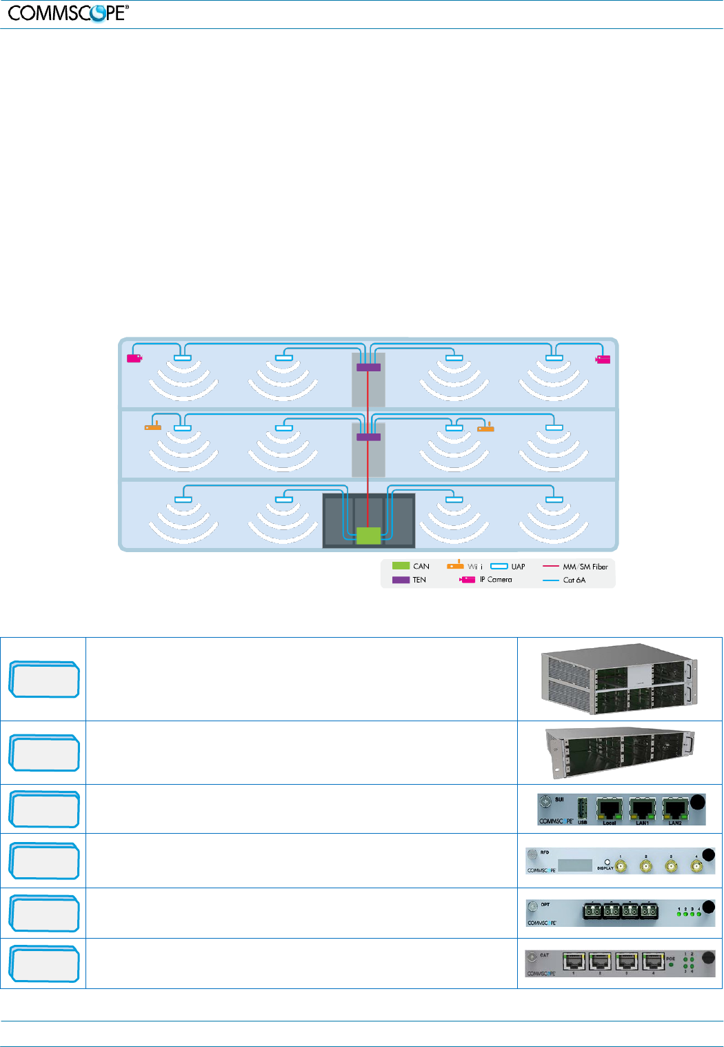
2. ION-E System Overview
The ION-E is a unified wireless infrastructure platform defined around IT based architecture. It brings together licensed wireless
and power, plus Gigabit Ethernet for Wi-Fi into one wireless network that can scale to building size and is technology and spectrum
agnostic and adaptive.
• Central Area Node (CAN): Server-level control and primary signal distribution. 2U and 4U subrack options are available.
• Transport Expansion Node (TEN): The secondary distribution point connected to a CAN using multimode or single mode
fiber.
• Universal Access Point (UAP): data and power through Category 6A twisted pair cabling. Supports gigabit Ethernet for
WiFi, IP cameras, or other devices in addition to wireless over a common cable.
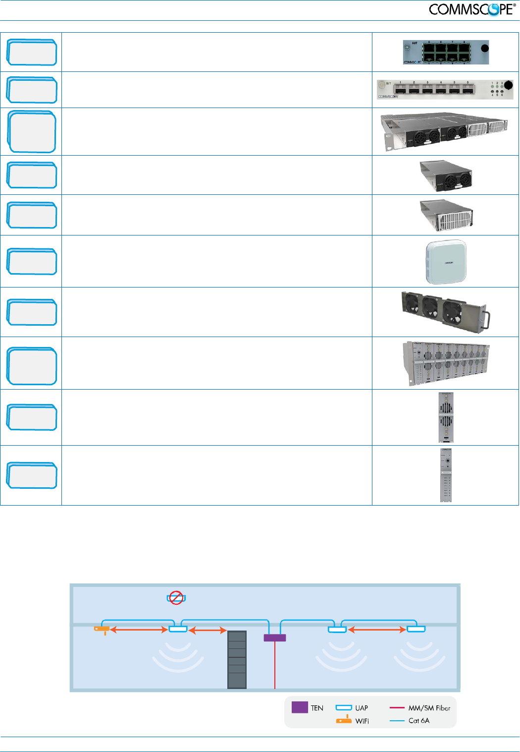
2.1. ION-E Components Overview
WCS-4
The WCS-4 is a 4U subrack. It is typically used as a CAN but can also
serve as a TEN.
WCS-2
The WCS-2 is a 2U subrack. It is typically used as a TEN, but can also
serve as a CAN.
SUI
The System User Interface card provides local and LAN Ethernet
connections and a USB port.
RFD The RF Donor card is the interface for RF signals between the CAN and
the BTS or eNode-B. Each of its four ports (QMA F) simultaneously
transmits and receives signals.
OPT
The OPtical Transport card provides a 10 Gb fiber connection between a
CAN and a TEN. Each card supports up to four SFP+ modules.
CAT
The Copper Transport card provides 10 Gb Cat6A connections between
the CAN or TEN and the UAP. The cards also supply the PoE to the UAPs.
M0201A0A_uc User’s Manual for ION®-E Page 4
Metal C
ab
i
ne
t
2. ION-E System Overview
AUT
The Auxiliary Unit Transport card provides a 1 Gb pass-through
connection between the CAN or TEN and the UAP for Wi-Fi, IP cameras,
or other 1 Gb Ethernet devices.
BIT
The Baseband Interface Transceiver card provides the fiber interface to
BBU ports. Up to six BBU port connections per card are supported.
Power
Supply
Subrack
The Power Supply subrack houses two 12 Vdc and two 57 Vdc modules to
supply power to the WCS subracks, UAPs, and connected devices.
12 VDC
The 12 Vdc modules plug into the power supply subrack to provide 12 Vdc
power to the WCS and e-POI subracks.
57 VDC
The 57 Vdc modules plug into the power supply subrack to provide 57 Vdc
power for the UAP and other PoE devices connected to a WCS subrack.
UAP
The Universal Access Point broadcasts up to 300 MHz of RF spectrum in
four bands. Plus it has a gigabit Ethernet port for ancillary devices.
FAN
The Fan tray and Filter modules cool the WCS and all of its cards. One fan
tray is used for a WCS-2. Two trays are used for a WCS-4.
e-POI
Subrack
The e-POI subrack supports up to 8 e-POI modules and an IFC module.
e-POI
The e-POI (Point of Interface) card is a low PIM attenuator. It reduces high
power RF signals from their source by 30 dB to interface to the RFD cards.
IFC
The IFC (Interface Card) is used to set the subrack number of the e-POI
subrack. It also provides a status LED for each of the e-POI modules in the
subrack.
2.2. UAP Ceiling Mounting
The UAP is equipped with a grounding screw located in the center of the unit, however, grounding is not required as UAPs are
classified as low-voltage devices and do not have internal power supplies. CommScope recommends checking your local and
national electrical codes to determine if grounding is a requirement.
W
iF
i
3m
mi
n
Install below ceiling grid
o
n
ly
2m min
Collocated
UAPs
(
M
I
M
O
)
3m
mi
n
M0201A0A_uc User’s Manual for ION®-E Page 5
Summary Alarm
2 A max
30 Vdc max
125 Vac max
3. ION-E
Hardware
3. ION-E Hardware
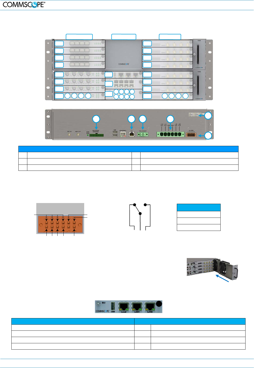
3.1. WCS-2 and WCS-4 Subracks
Left Middle Right
L8 R8
L7 R7
L6 R6
L5 R5
L4
L3
L2
L1 1 2 3 4
M3 R4
M2 R3
R2
M1 5 6 7 8
1 2 3 4 R1
1 2 3 4
E
A B C D
F
WCS subrack rear connectors
A
RECTIFIER CONTROL: PSU communication
D
POWER 12 Vdc and 55 Vdc Inputs
B
POI: POI Communication
E
Grounding Bolts
C
POI POWER 12 Vdc to e-POI subrack
F
ALARMS: Dry contact input and output
Alarms Connector
• Four opto-isolated (chassis ground referenced) dry contact inputs to monitor external devices
• One summary alarm relay that energizes when specific alarms are triggered
A
L
A
RM
S
1 2 3 4 5 6
Relay
C
OM
G
ND
Relay
NC
IN1 IN2 IN3 IN4
R
e
l
a
y
NO
NC COM NO
WCS Fan Modules and Filters
• Fan modules may be replaced without system interruption.
• The fan modules must be installed for WCS operation!
• Blank panels are required for all empty card slots to maximize airflow.
3.2. System User Interface Card (SUI) – for external communications
Ports
Port LEDs
Local: Local laptop - fixed IP address
Off
No link
LAN1: To collocated WCS subracks
Green
Link established - Activity (flashing)
(Left LED)
LAN2: LAN or modem - DHCP or specified fixed IP address
Off
10 Mb connection established (Right LED)
USB: USB 2.0 for transferring files
Yellow
100 Mb connection established (Right LED)
M0201A0A_uc User’s Manual for ION®-E Page 6
3. ION-E Hardware
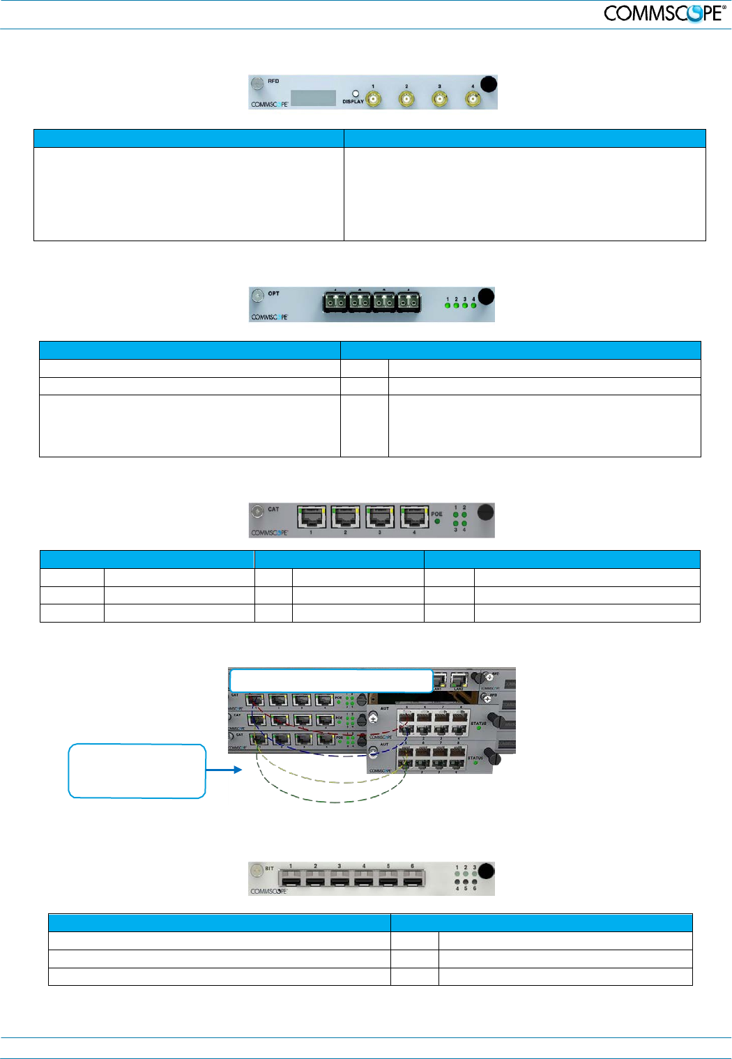
3.3. RF Donor Card (RFD) – RF Signals to/from eNodeB / BTS
Ports 1-4
LCD Display
Connector type: QMA female
RF Paths: Simultaneous transmit and receive
Protection: Relays with adjustable trip threshold
Frequency: 380 – 2700 MHz
• Push the Display button to turn on the display’s backlight.
• Push the button repeatedly to cycle through the four ports.
• The first line of the display shows the port number and
band.
• The second line of the display shows the service provider
or “multiple” if multiple providers are connected to the port.
3.4. Optical Transport Card (OPT) – Fiber Connection between CAN and TEN
Ports 1-4
Port LEDs
Slots: Accept SFP+ plug-in modules
Off
No power or card is plugged into wrong slot in a TEN.
Type: 10 Gbps single mode or multimode
Green
Optical link is established.
Purpose: High speed fiber connections between
CAN and TEN. OPT may be installed in slots L1-L8
in a CAN but the OPT must be installed in slot R1
in a TEN.
Yellow
Card is powered and initialized but link is not
established. When installed in a TEN, only port 1
LED is functional.
3.5. Copper Transport Card (CAT) – Signals and PoE to UAPs
Ports 1 - 4: RJ45 CAT6A
Port LEDs 1 - 4
PoE LED
Off
No Link
Off
Card is unplugged
Off
No PoE supplied to UAPs
Green
10G link
Red
Fault
Green
PoE supplied to one or more UAPs
Yellow
1G link
3.6. Auxiliary Unit Transport Card (AUT) – 1G pass through
1G pass-through for IP devices
CAT card ports are
mapped one-to-one
to AUT ports.
3.7. Baseband Interface Transceiver Card (BIT) – Fiber to the BBU
Ports 1-6
Port LEDs
Slots: Accept SFP+ plug-in modules
Off
No power
Type: Single mode or multimode
Green
Optical link is established
Purpose: Fiber connections to BBU using CPRI protocols
Yellow
Card is powered but link is not established
M0201A0A_uc User’s Manual for ION®-E Page 7
LED
Color
Status
Blue
Transmitting – no alarms
Blue
Unit Identifier (flashing)
Yellow
Alarm
4.
Installation
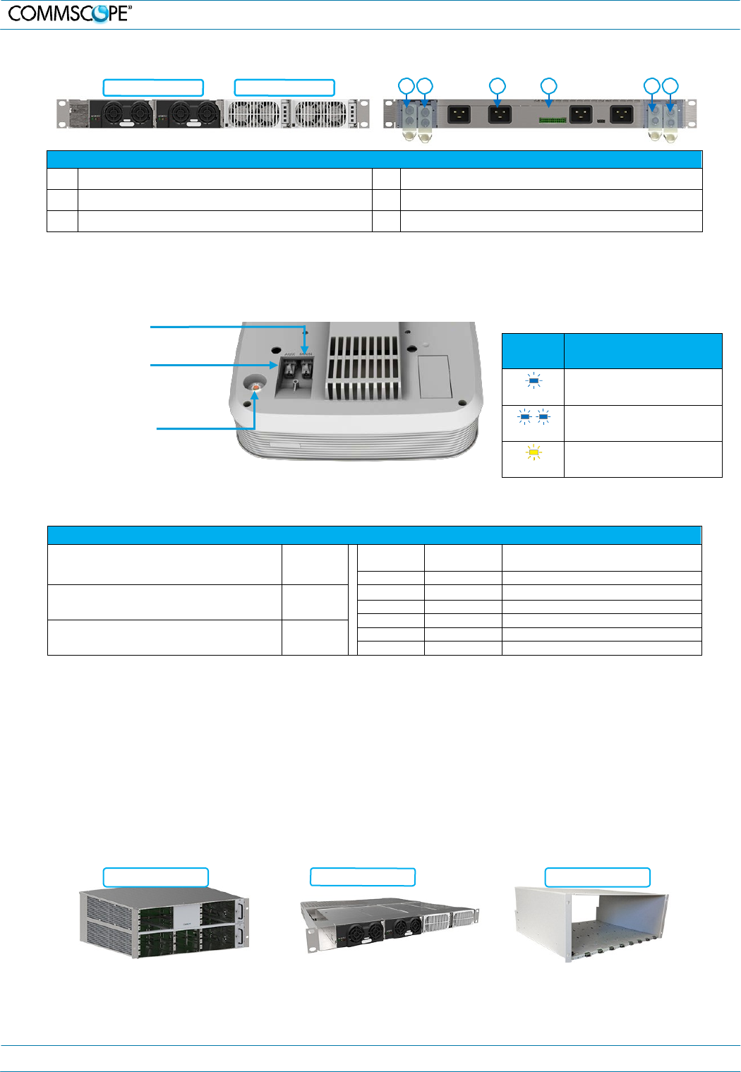
3.8. Power Supply Subrack
12 Vdc modules 57 Vdc modules A B C D E F
Power supply subrack rear connectors and terminals
A (+) 57 Vdc Output – Positive (Red Wire) D Rectifier control connector (24 pin) to WCS
B (–) 57 Vdc Output – RTN Negative (Black Wire) E (+) 12 Vdc Output – Positive (Red Wire)
C AC Input (IEC 60320 C19) F (–)12 Vdc Output – RTN Negative (Black Wire)
3.9. Universal Access Point (UAP)
The UAP is intended for indoor use only.
MAIN Port (RJ45)
Provides data and PoE to UAP
over CAT6A
AUX Port (RJ45)
Provides data and PoE to 2nd UAP
or 1G devices
Power Switch
Prior to disconnecting the Cat6A cables,
the red button must be pressed to shut
down the unit.
It may also be shut down via software.
Specifications
Nominal passband gain:
Le gain nominal en bande passante
20 dB
MHz
MHz
Nominal bandwidth (MHz)
La largeur de bande nominale
728
746
18
Rated mean output power
La puissance moyenne de sortie
+18 dBm
746
756
10
869
894
25
1930
1995
65
Input / Output Impedance
Les impédances d’entrée et de srtie, et
50 Ohms
2110
2155
45
2620
2690
70
The Manufacturer's rated output power of this equipment is for single carrier operation. For situations when multiple carrier signals are present, the
rating would have to be reduced by 3.5 dB, especially where the output signal is re-radiated and can cause interference to adjacent band users.
This power reduction is to be by means of input power or gain reduction and not by an attenuator at the output of the device.
La puissance de sortie nominale indiquée par le fabricant pour cet appareil concerne son fonctionnement avec porteuse unique. Pour des appareils
avec porteuses multiples, on doit réduire la valeur nominale de 3,5 dB, surtout si le signal de sortie est retransmis et qu'il peut causer du brouillage
aux utilisateurs de bandes adjacentes. Une telle réduction doit porter sur la puissance d'entrée ou sur le gain, et ne doit pas se faire au moyen d'un
atténuateur raccordé à la sortie du dispositif.
4. Installation
4.1. Mechanical Installation of WCS and e-POI
Rack Mounting – Support Rails Requirements
WCS Subrack
Support rails not required
If used, support rails may not block airflow.
PSU Subrack
Support rails required
Rails must not contact DC
terminals or cable lugs.
e-POI Subrack
Support rails required
M0201A0A_uc User’s Manual for ION®-E Page 8
4. Installation
Mounting Order and Spacing
One RU (rack unit) of air
space must be reserved
above the power supply
subrack at all times.
One RU vent panel above PSU
One RU vent panel above PSU
TEN Card Placement
• OPT in bottom right side slot (R1)
- Use port R1.1 for the connection (to CAN)
• CAT in left side bottom four slots (L1-L4)
• RFD in all other right side slots (R2-R4) if required
• SUI in slot M3
• AUT in slots M1 and M2
Install SFP+ Modules in OPT and BIT
Cards
R1.1 Port – Fiber to CAN
Plug SFP+ modules into
an available socket. To remove, pull module out of
slot with extraction lever.
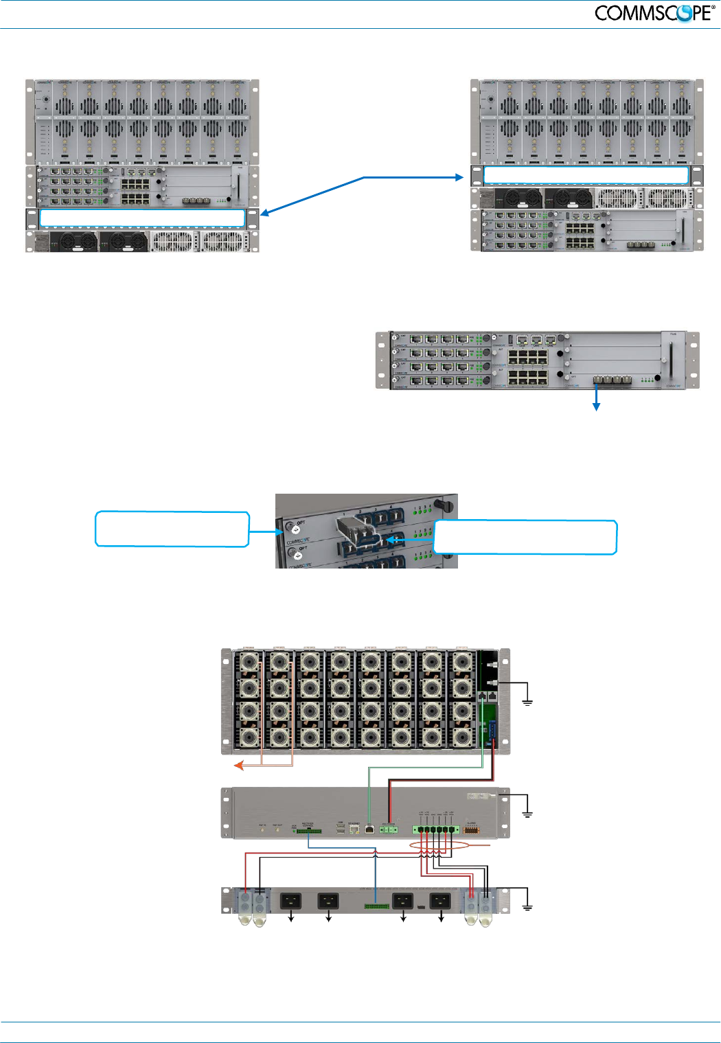
4.2. Back of Rack – Power and Communication Cabling
Connect rear panel power, communications, and control cables as shown below:
e-POI
Subrack
ground
(required)
To/from
eNodeB
e-POI communications
e-POI power
WCS
Subrack
ground
(required)
WCS DC power
cable
PSU
Rectifier
control
85 to 264 Vac
85 to 264 Vac
Subrack
ground
(required)
M0201A0A_uc User’s Manual for ION®-E Page 9
5. ION-E Software
5. ION-E Software
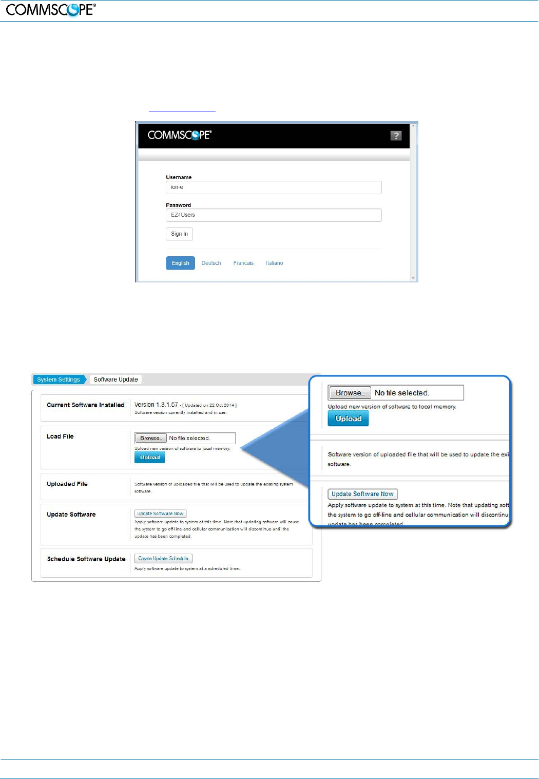
5.1. Login Page
1. Default username “ion-e”
2. Default password: “EZ4Users” The password is case-sensitive.
3. Default Local IP Address: http://172.16.0.1
5.2. Software Update
The software update will automatically update the firmware of every component in the system that requires an update.
It will not update components with current firmware.
1. Under the System Configuration tab | System Settings tab, click the Software Update link located in the System Settings
column.
2. Use the Browse and Upload buttons to upload a software update file.
3. Click the Update Software Now button to start the update immediately. This will take the system offline and discontinue
cellular communication while the update is in progress.
4. Click the Create Update Schedule to set a time for the update when there is less cellular traffic.
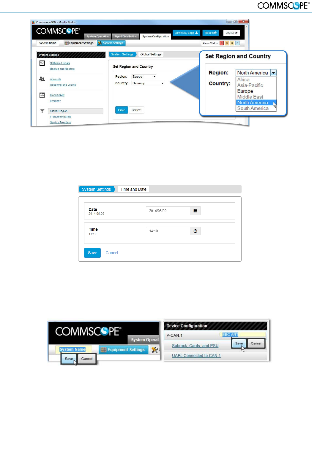
5.3. Important Setup Tasks
Set region of operation
The ION-E measurement receiver will operate more efficiently once the region of operation is specified because this
limits the initial frequency scans to those bands supported in the particular region.
1. Under the System Configuration tab | System Settings tab, click the Global Region link located on the left side of the page
to open the Global Settings tab.
2. Select the Region and Country from the associated drop-down lists.
M0201A0A_uc User’s Manual for ION®-E Page 10
5. ION-E Software
3. Click the Save button.
Set Time and Date
The time and date should be entered to ensure that alarms and log files have accurate time stamps based on the local
time.
1. Under the System Configuration tab | System Settings tab, click the Time and Date link located in the System Settings
box.
2. Enter the Time and Date in the appropriate fields or by clicking on the time and date buttons.
3. Click the Save button.
Enter or Change System, CAN, TEN, and UAP names
Entering meaningful names helps you identify and locate systems and components. To enter or change the name
(location) for the System or a CAN, TEN, or UAP:
1. Click in the System Name field at the top left of any page, type the name, and click the Save button.
2. Click in the Name (location) field adjacent to a CAN, TEN, or UAP, type the name, and click the Save button.
5.4. Channel Detection
Detect Channels – Manual Scan
ION-E requires detection of all signals that will be distributed. This ensures that the user will always know what signals
are being distributed by the system. The measurement receiver automatically scans and detects available channels.
However, to optimize system efficiency, running user-defined manual scans for each connected RF port is strongly
recommended. Specifying the band for a port will reduce the required scan time. To run a manual channel scan:
M0201A0A_uc User’s Manual for ION®-E Page 11
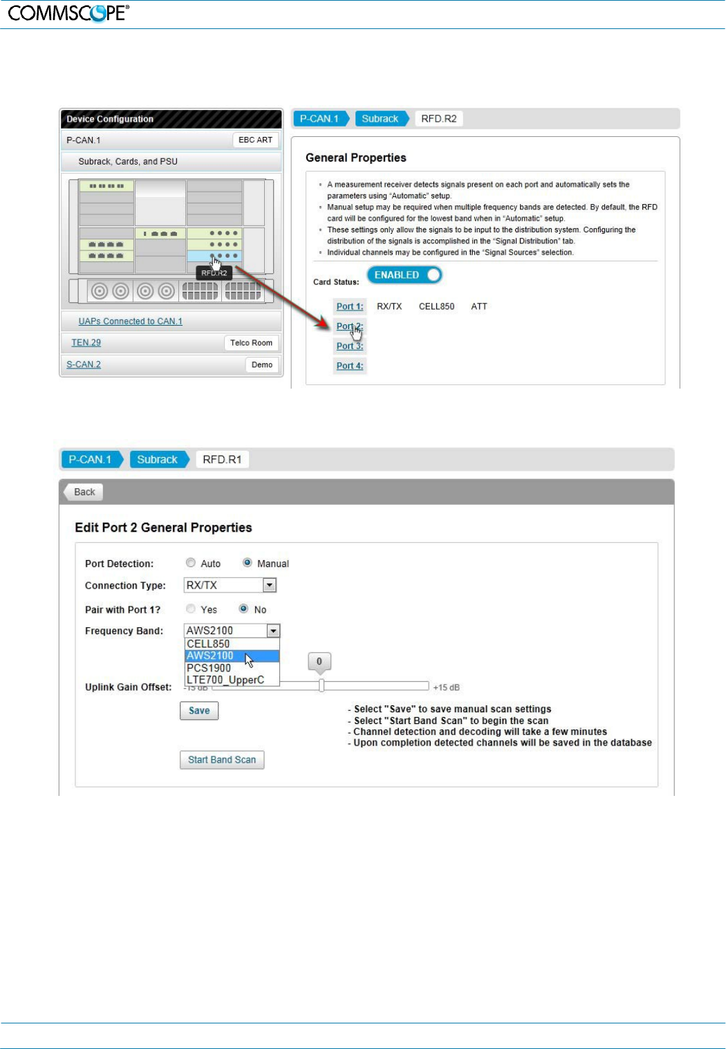
5. ION-E Software
1. Under the System Configuration tab | Equipment Settings tab, click a CAN link located in the Device Configuration box.
2. Click on the Subrack, Cards and PSU link to view the WCS subrack of the CAN.
3. Click on an RFD card to select it, which opens its General Properties page.
4. Click on an available Port link to open its Edit General Properties page.
5. Click to select the Manual Port Detection radio button.
6. Select a band from the Frequency Band drop-down list.
7. Click the Save button to save the scan settings.
8. Click the Start Band Scan button to start the scan. If a scan is already in progress, a popup window will appear. Click the
Add to Queue button in that window to place the scan task into the queue.
Measurement Receiver
The scan tasks results are available on the measurement receiver pages, which provide the detailed information about
the detected channels.
To view ION-E measurement receiver status, scan results, and scan history:
1. Under the System Operation tab click the Scan Status link located in the System Operation and Performance box to view
the Current Status of the measurement receiver. The Scan History is also accessible from this page.
M0201A0A_uc User’s Manual for ION®-E Page 12
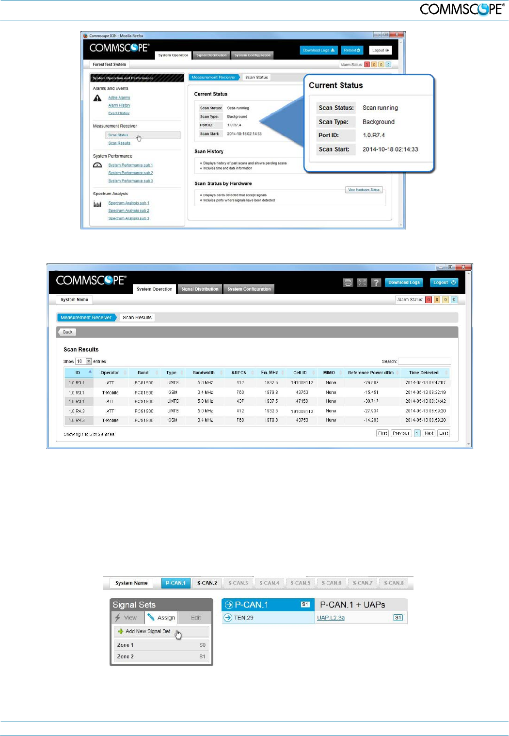
5. ION-E Software
2. Under the System Operations tab, click the Scan Results link located in the System Operation and Performance box to
view the Current Status of the measurement receiver.
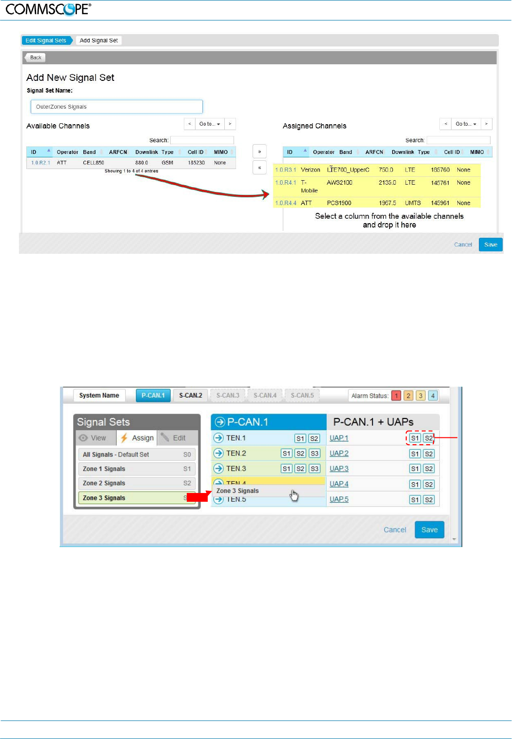
5.5. Signal Distribution
The ION-E uses signal sets to group the detected signals to simplify signal routing to the radiating elements
throughout the system. First the user must create and define the signal sets by assigning channels to the sets. The
signal sets are then assigned as needed using drag and drop functionality to route the signals to the TENs and UAPs.
Create and Edit Signal Sets
1. Click on the Signal Distribution tab to open the page.
2. Select a set from the Signal Sets list and click the Edit button to edit an existing set.
3. Click on the Add a New Signal Set link to open the Add Signal Set page to create a new set.
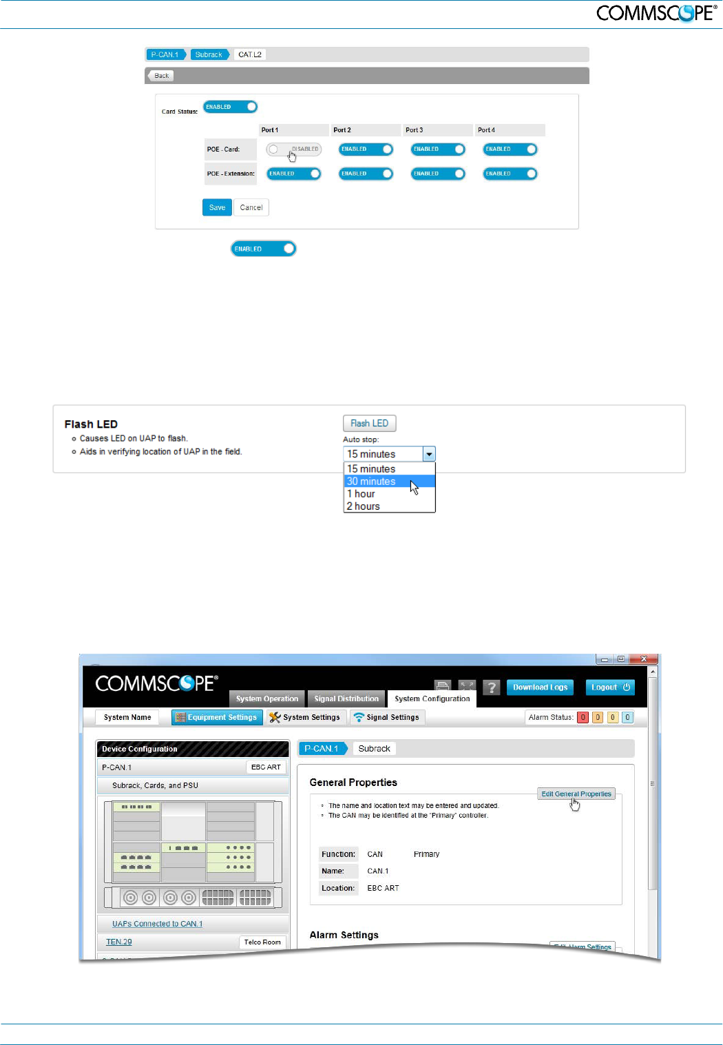
4. Enter a Name for the signal set in the Signal Set Name field.
5. Click to select a channel from the Available Channels list or shift click to select multiple channels and drag them onto the
Assigned Channels list.
M0201A0A_uc User’s Manual for ION®-E Page 13
5. ION-E Software
6. Click the Save button to save the Signal Set.
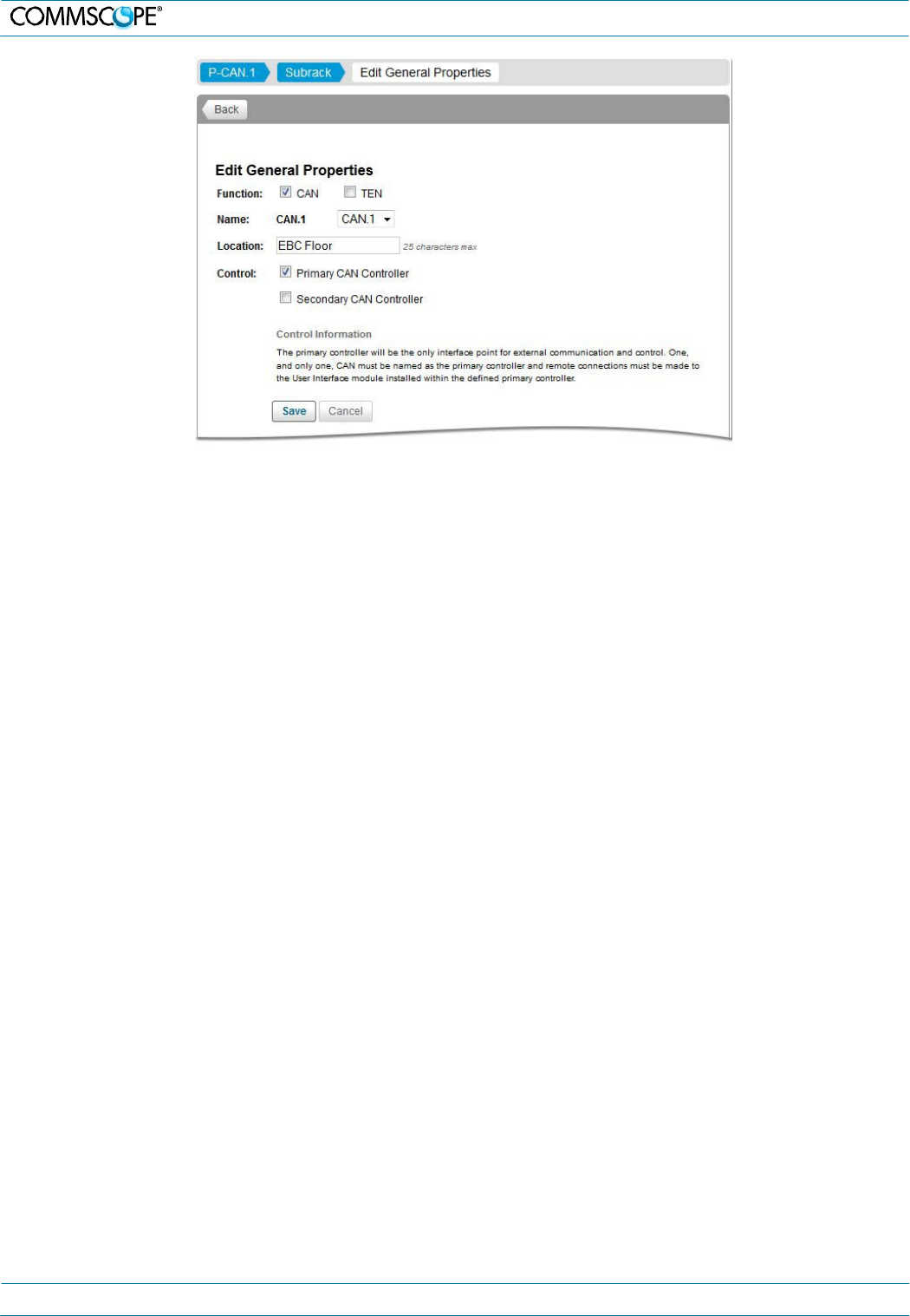
Assign Signal Sets (Direct signal traffic to TENs and UAPs)
Signal Sets, which are a user-defined set of channels, can be quickly assigned to CANs and all UAPs assigned to
them, TENs and all UAPs assigned to them, or to individual UAPs on the Signal Distribution page.
1. Click on the Signal Distribution tab to open the page.
2. Assign a signal set by:
o Clicking on a signal set and dragging it onto the a TEN or UAP (set icons adjacent to the device name indicate the
sets assigned to a TEN or UAP)
o Clicking on a signal set to select it (green highlight) and then clicking on each TEN or UAP to which you wish to
assign the signal set.
Signal sets
assigned to
UAP
3. Click the Save button after you’ve assigned each signal set
5.6. Disable Modules and Ports
ION-E modules and/or ports can be quickly enabled or disabled. You should always disable a CAT card or its
ports before disconnecting a CAT6A cable supplying power to a UAP to prevent damage to the connector.
You may also wish to disable a card in the system that is not being used to reduce power consumption and heat
dissipation. To disable a module or one of its ports:
1. Under the System Configuration tab | Equipment Settings tab, click a CAN link or TEN link located in the Device
Configuration box.
2. Click on the Subrack, Cards and PSU link to view the WCS subrack of the CAN or TEN.
3. Click on a card to select it and open its General Properties page.
M0201A0A_uc User’s Manual for ION®-E Page 14
5. ION-E Software
4. Click on the Enabled /Disabled button to toggle state of the module or its ports.
5.7. Flash UAP LED
To place the UAP LED into blue flashing mode to verify the identity and location of a UAP:
1. Under the System Configuration tab | Equipment Settings tab, click a CAN link under Device Configuration.
2. Click on the UAPs Connected to CAN link or click on a TEN link and then click on the UAPs Connected to TEN link.
3. Click on a UAP link to open its properties page.
4. Select an Auto stop time from the drop-down list and click the Flash LED button.
5.8. Change WCS Subrack Function
WCS 4U and WCS 2U subracks are both capable of functioning as CANs or TENs. By default the WCS 4U is
designated as a CAN and the WCS 2U is designated as a TEN. To change the function of a WCS subrack:
1. Under the System Configuration tab | Equipment Settings tab, click a CAN link located in the Device Configuration box.
2. Click on the Subrack, Cards and PSU link to view the WCS subrack of the CAN. Or click on a TEN link and then click on
the Subrack, Cards and PSU link for that TEN to view the WCS subrack of the TEN.
3. Click the Edit General Properties button to open the General Properties page.
M0201A0A_uc User’s Manual for ION®-E Page 15
5. ION-E Software
4. Click in the CAN or TEN checkbox to assign the function of the subrack. If CAN is checked, click in the Primary or
Secondary checkbox and select a CAN Name from the drop-down list.
5. Enter a location name for the subrack in the Location field.
6. Click the Save button to save the subrack function assignment. A popup window will appear to notify the user that the
system will reboot.
M0201A0A_uc User’s Manual for ION®-E Page 16