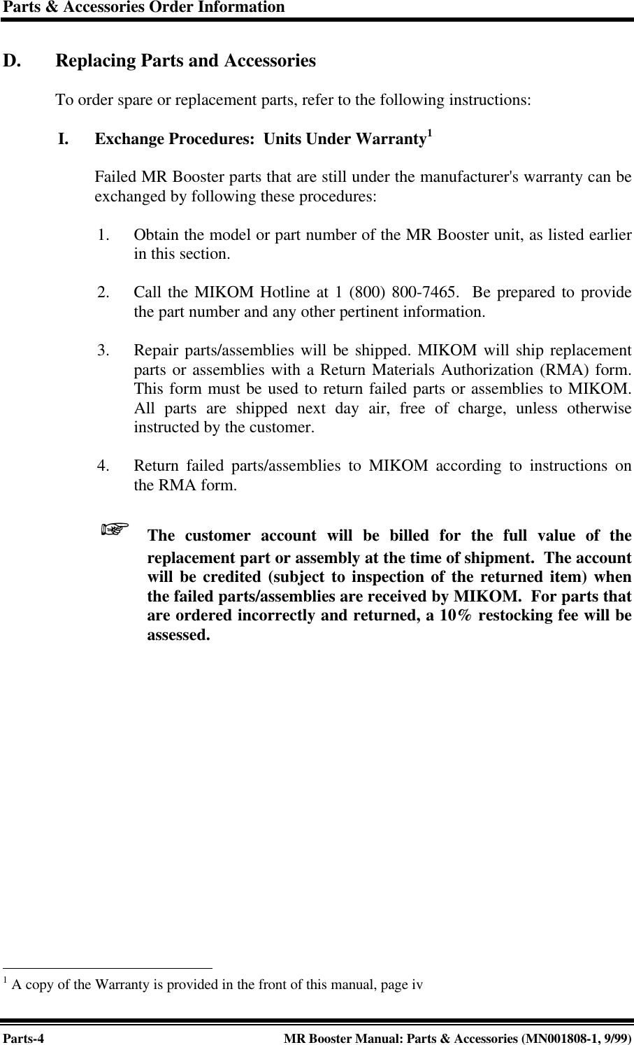
Andrew Wireless Innovations Group MRB-LMR Band Selective RF Booster User Manual MN1808 1
Andrew Wireless Innovations Group Band Selective RF Booster MN1808 1
UserManual.wiki
>
Andrew Wireless Innovations Group
>
MRB LMR User Manual
manuals
Navigation menu
Upload a User Manual
Namespaces
Wiki Guide
HTML
PDF
Info
Views
User Manual
Discussion / Help
Navigation
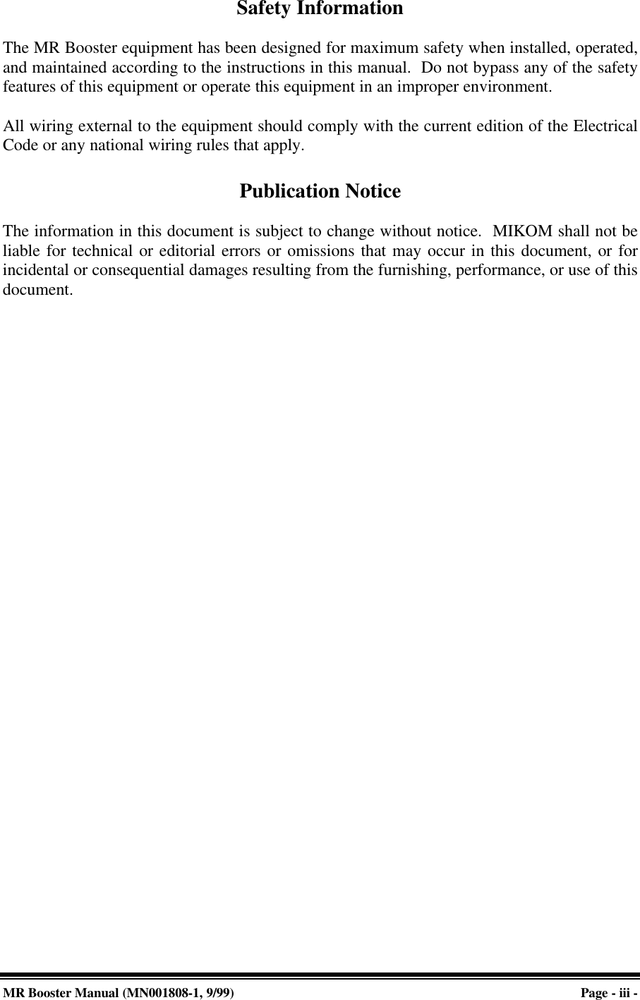
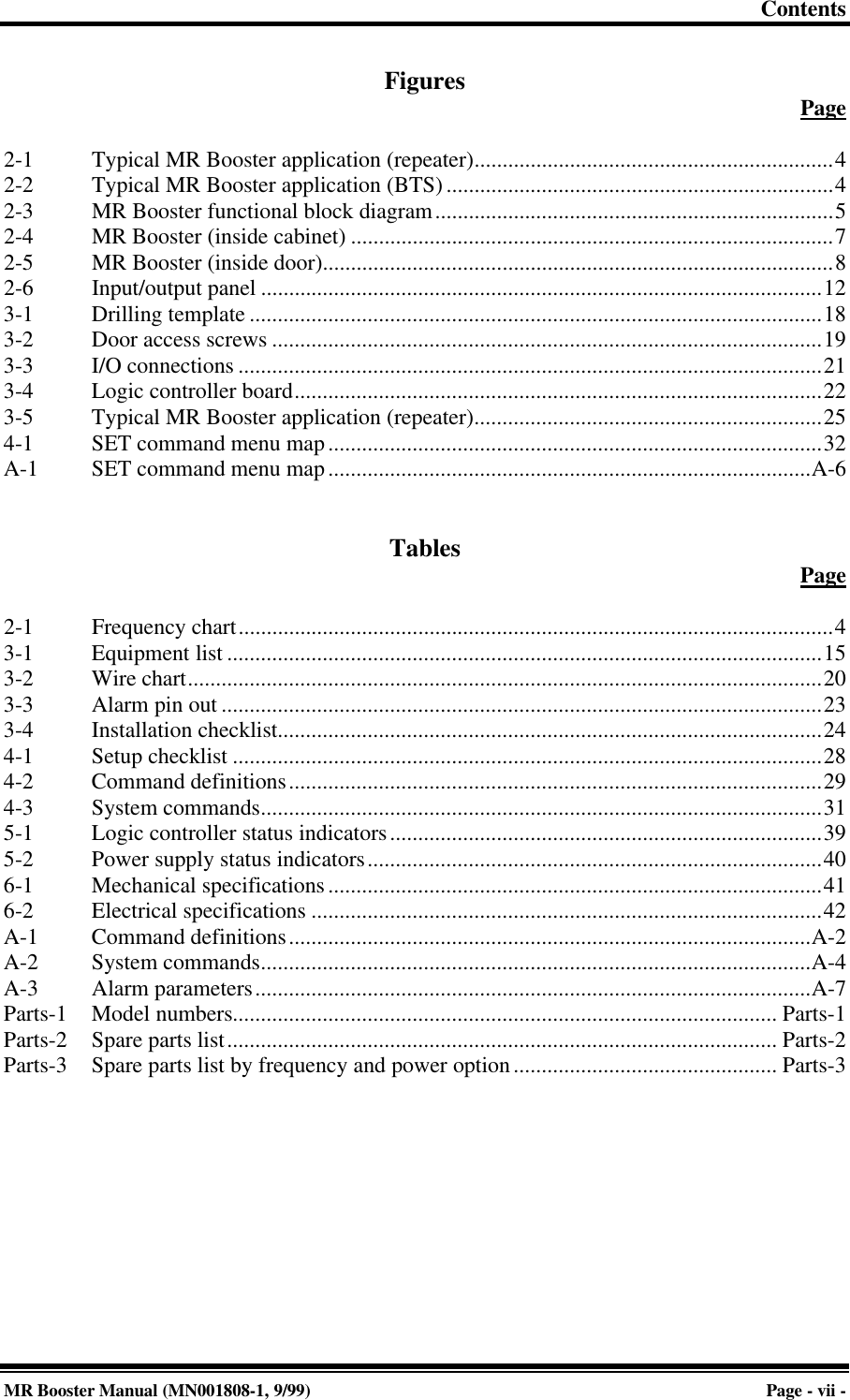
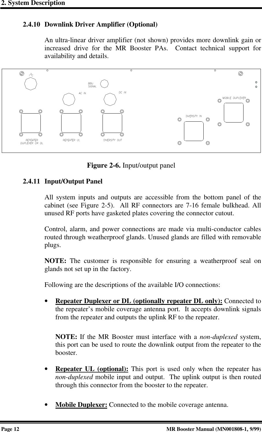
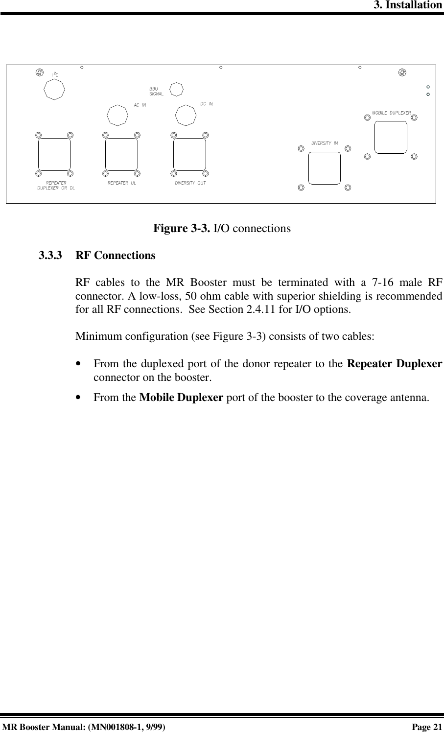
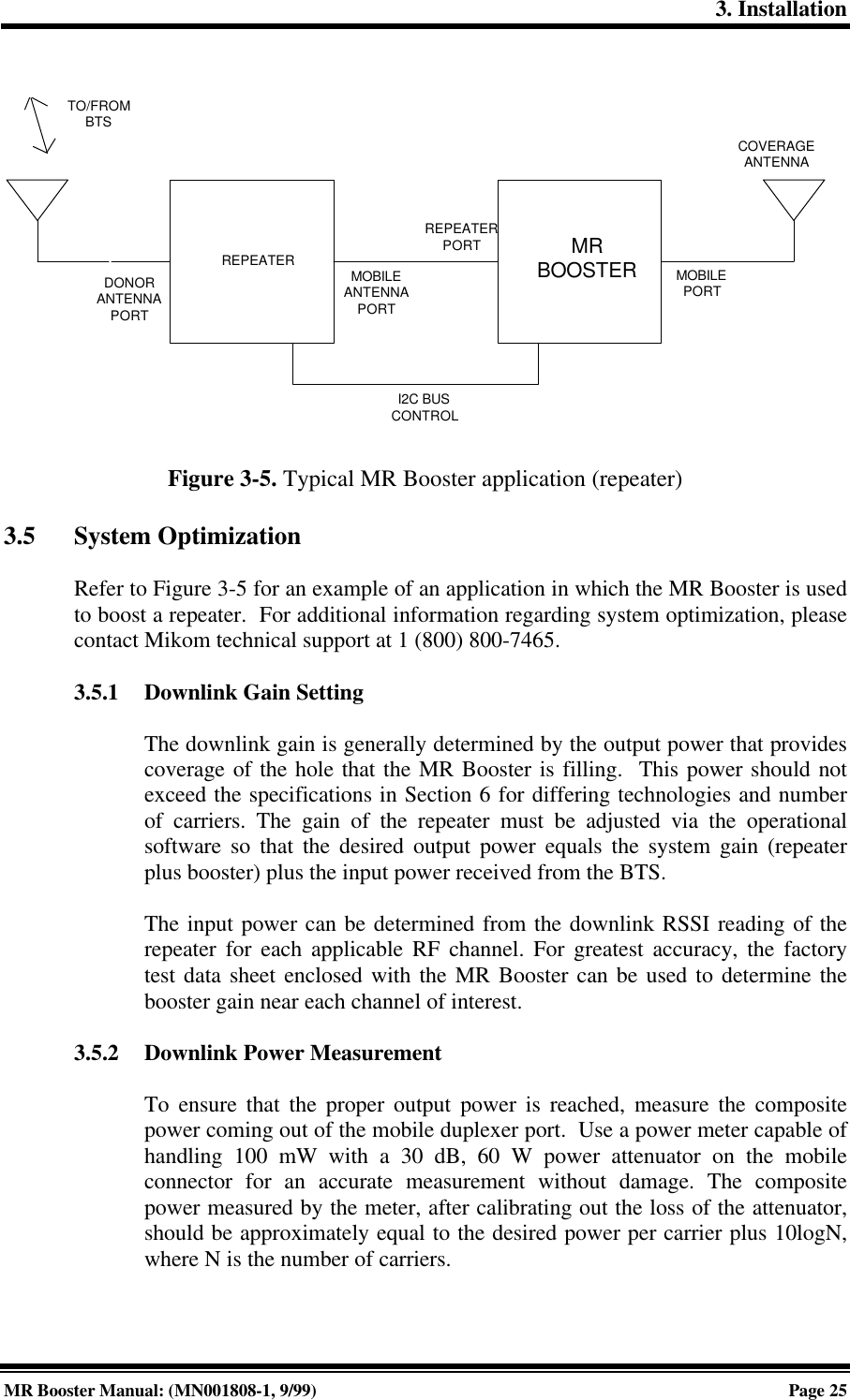
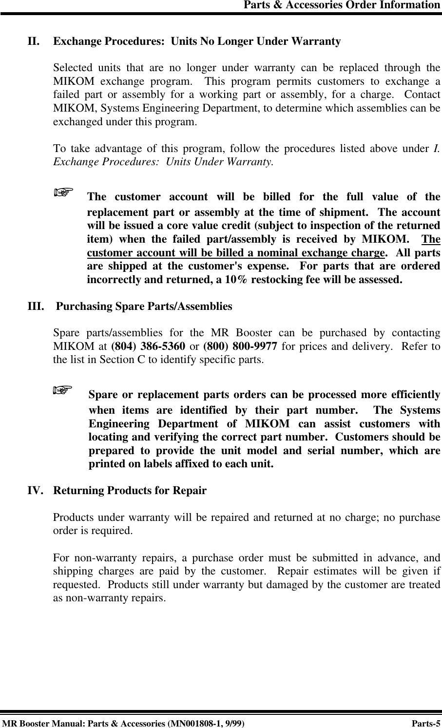
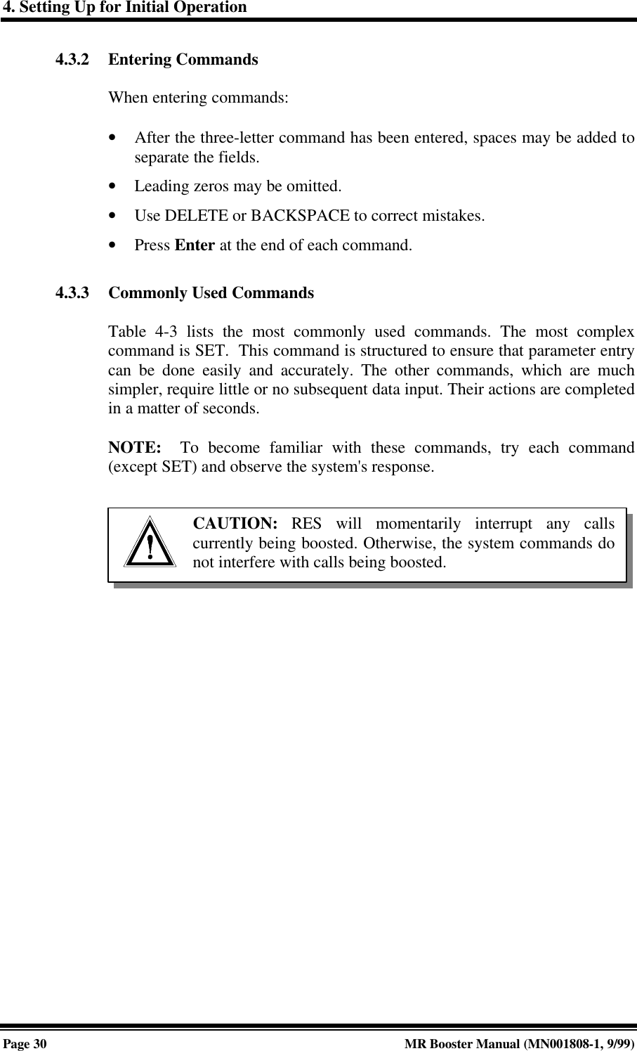
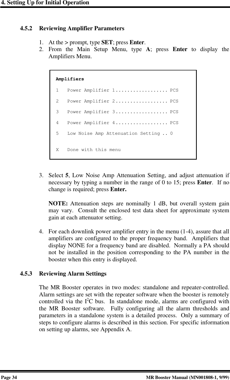
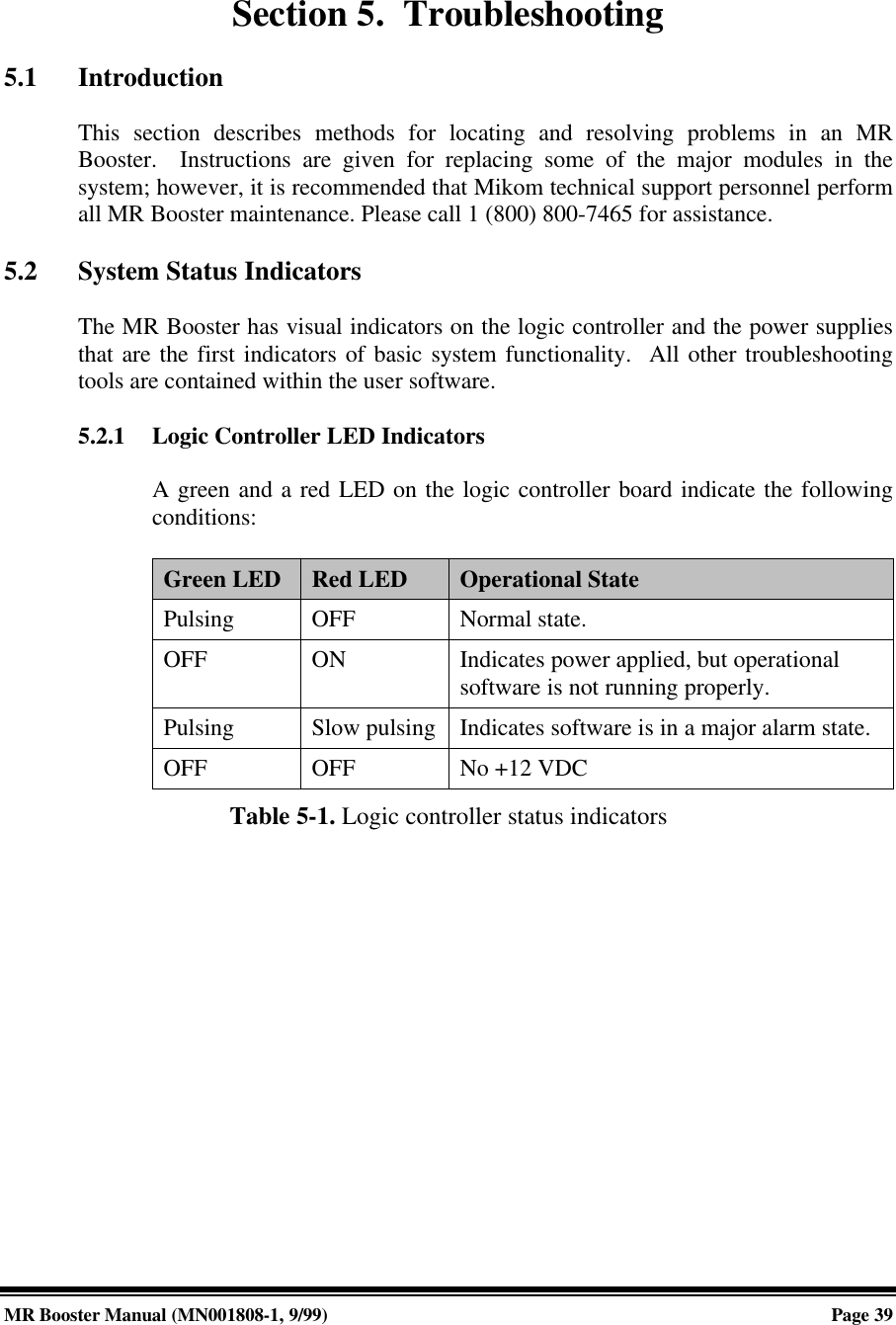
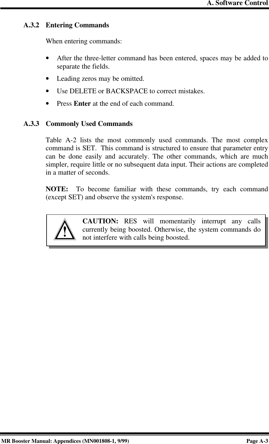
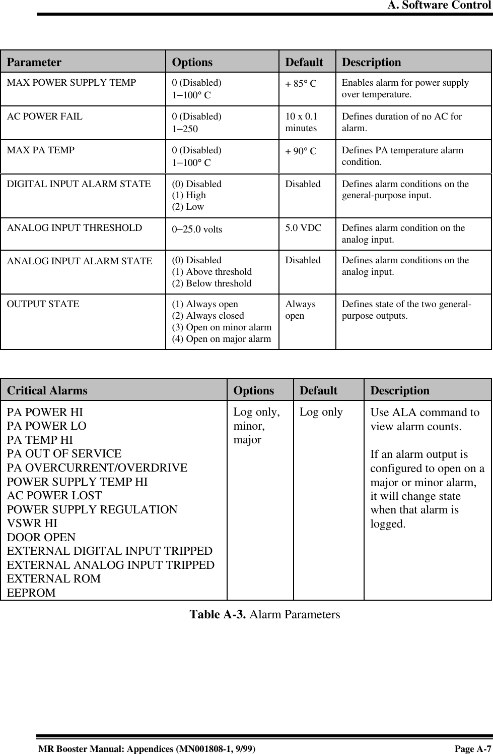
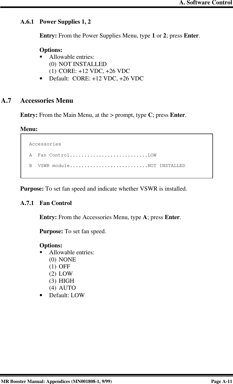
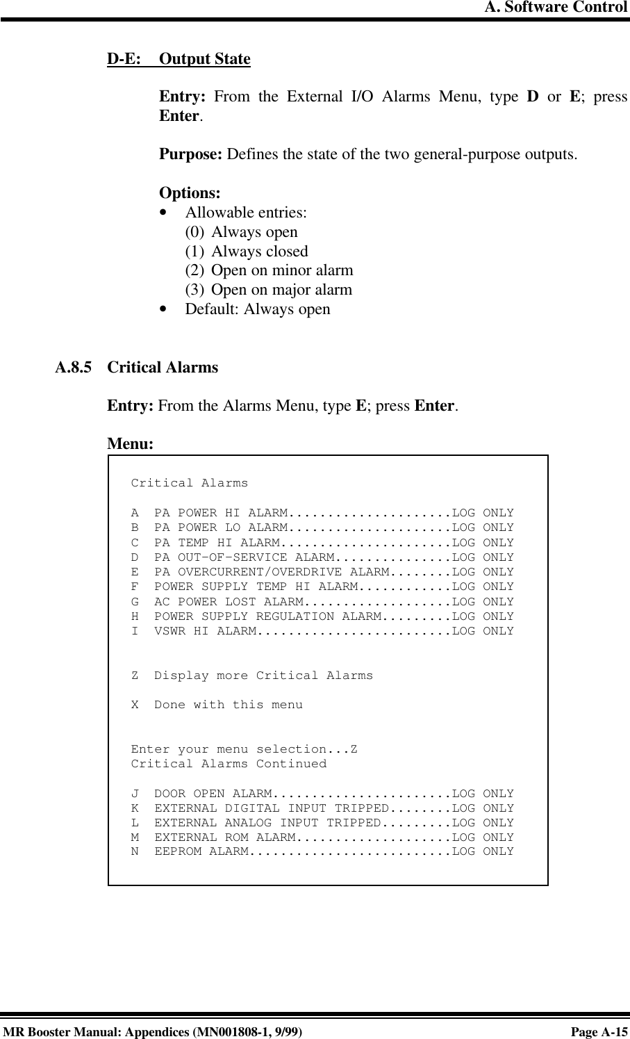
![4. Setting Up for Initial OperationMR Booster Manual: (MN001808-1, 9/99)Page 293. Power up the MR Booster. After about two seconds, the terminal should respondwith a welcome message.• If the response is garbled, check the terminal setup.• If there is no response, turn the booster OFF, then ON again. If there is stillno response, turn the unit OFF. Recheck the power hookup and the terminalhookup and configuration.4.3 Basic CommandsFollowing are basic rules and key commands for use with the MR Booster operatingsoftware.Symbol Definition><CTRL><ESC>Command Prompt. The system uses this prompt character to indicateit is ready to accept commands.Control Key. Used in combination with other keys.Escape Key. Escape is a single key marked ESC on most keyboards.Table 4-2. Command definitions4.3.1 SyntaxSystem commands consist of three letters followed by a maximum of threedata fields, as follows:COM [FIELD 1 -] [FIELD 2 =] [FIELD 3] Enter• COM: Three-letter command.• FIELD 1: Up to four hex characters followed by a dash (-).• FIELD 2: Up to four hex characters followed by an equal (=) sign.• FIELD 3: Up to two hex characters.• Enter: Press the Enter key after each command.NOTE: Few commands require entry of data fields. After a command hasbeen entered, the system will prompt for data it needs. The system will ignoreunneeded data fields.](https://usermanual.wiki/Andrew-Wireless-Innovations-Group/MRB-LMR/User-Guide-104437-Page-37.png)
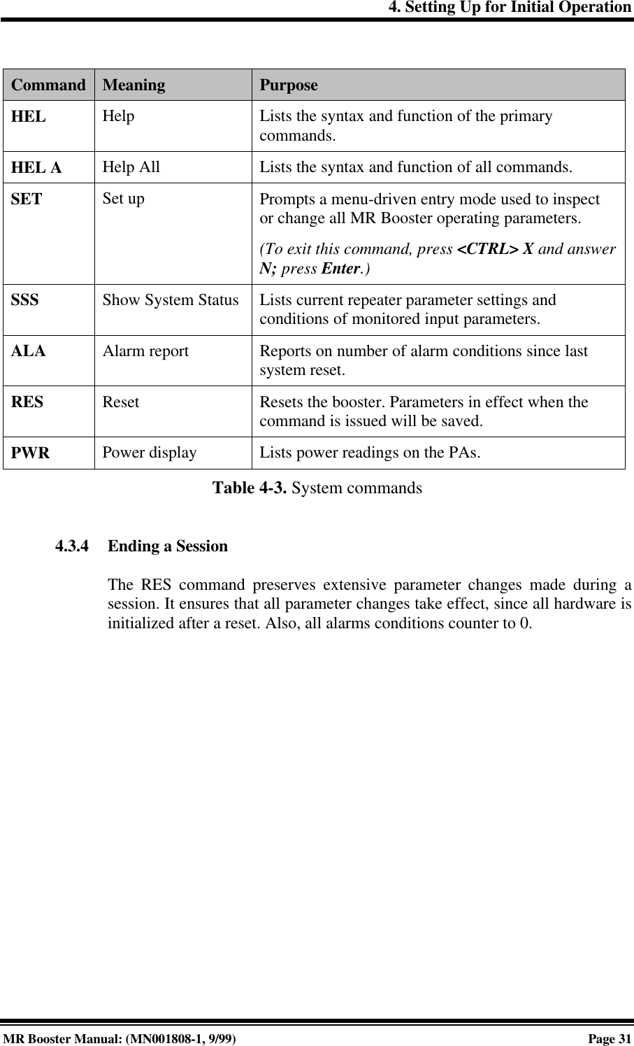
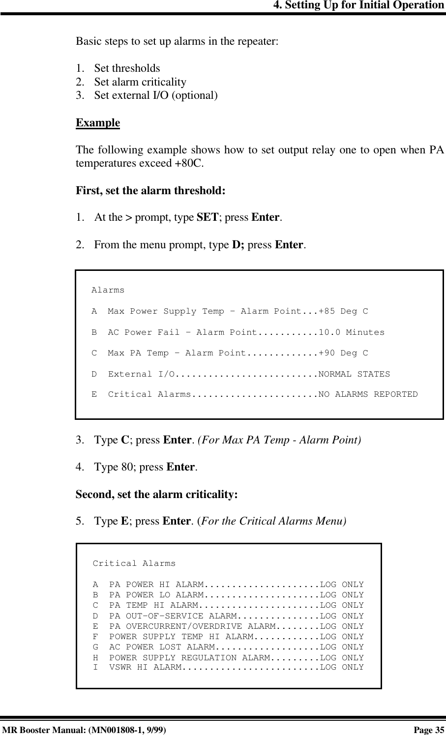
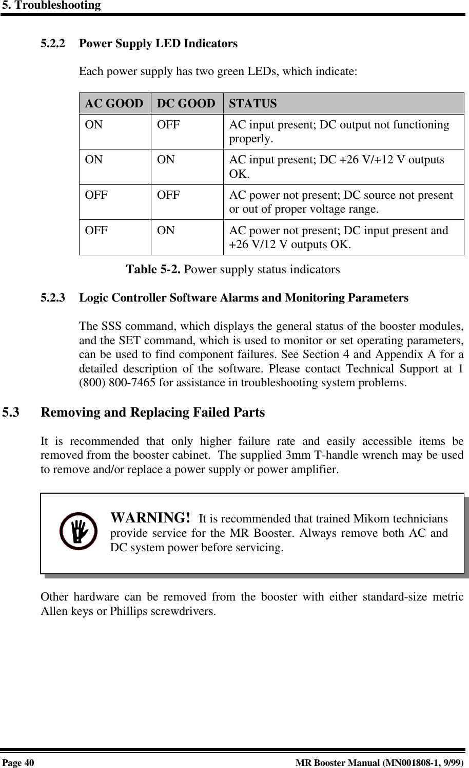
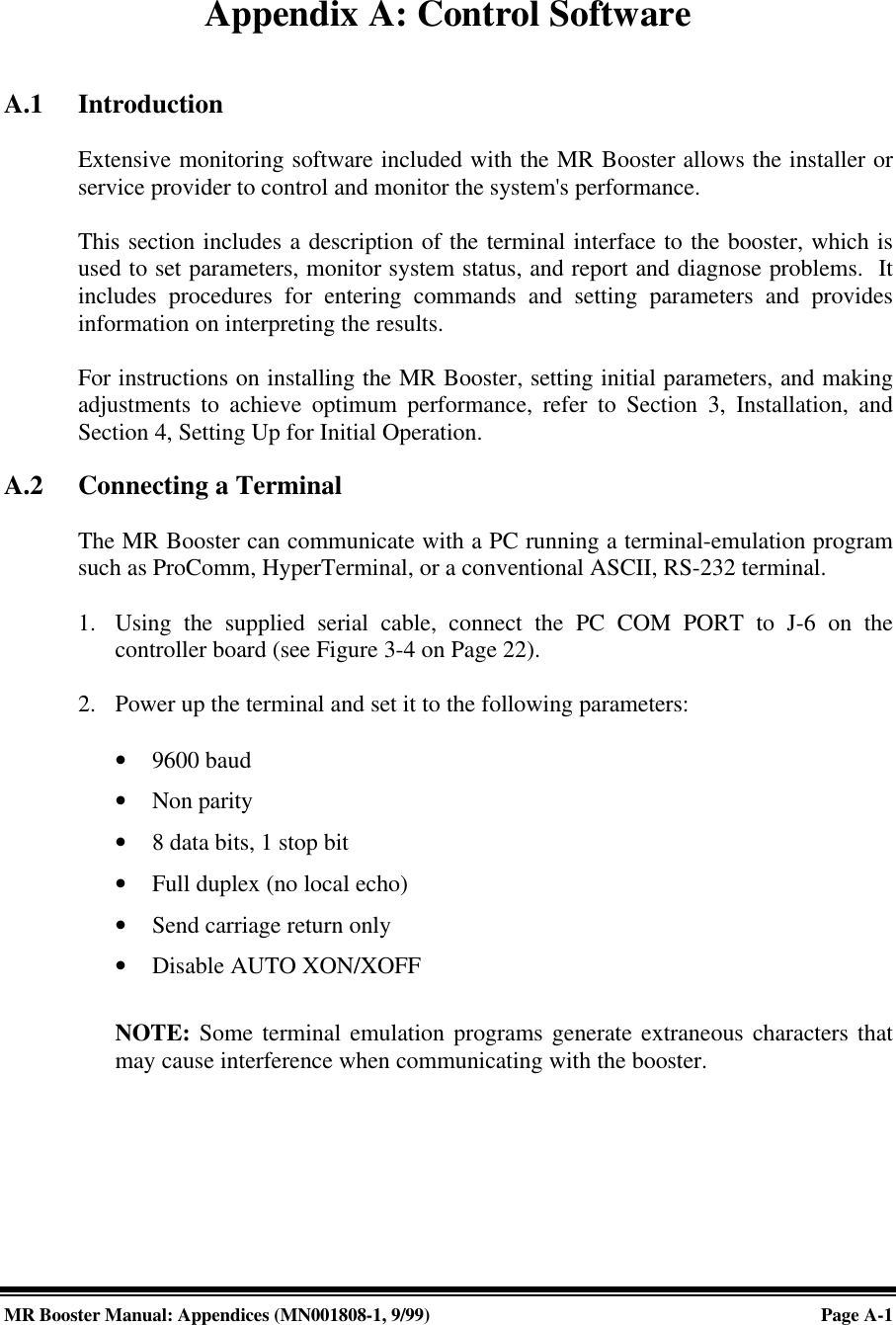
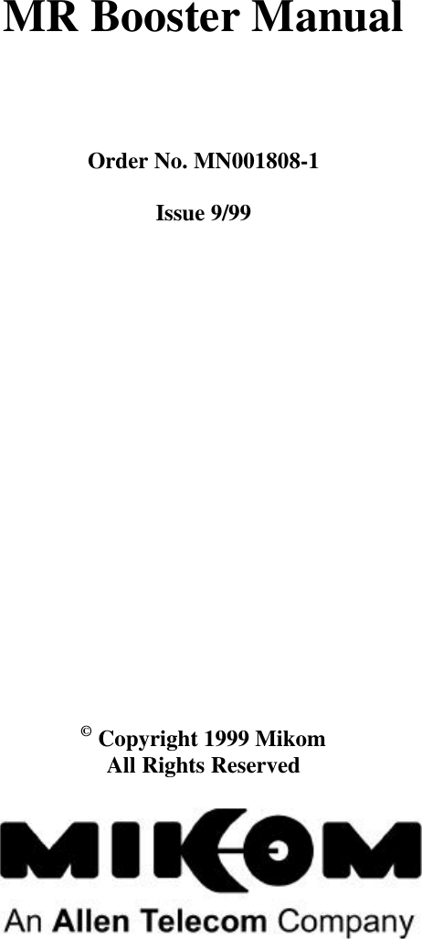
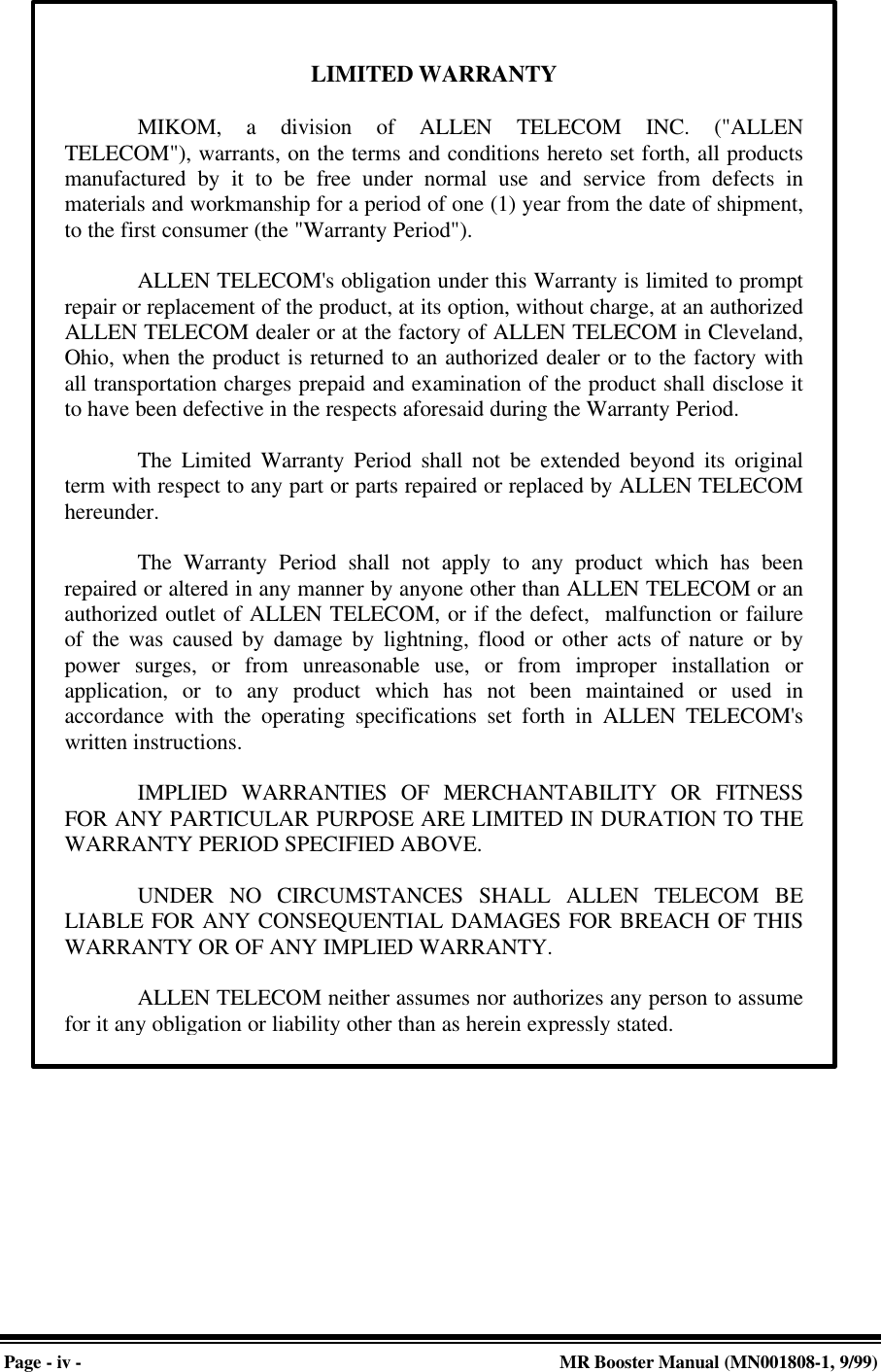
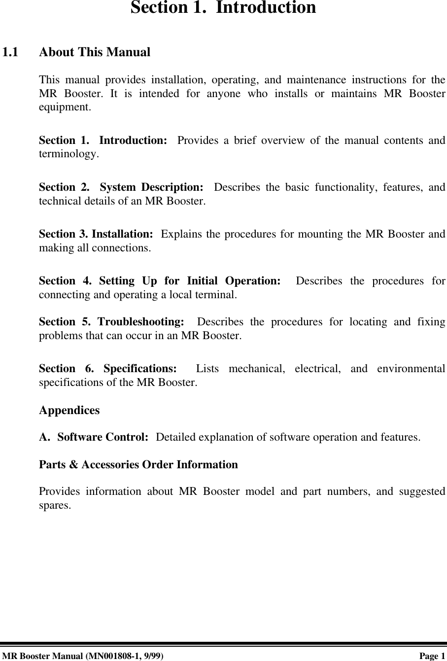
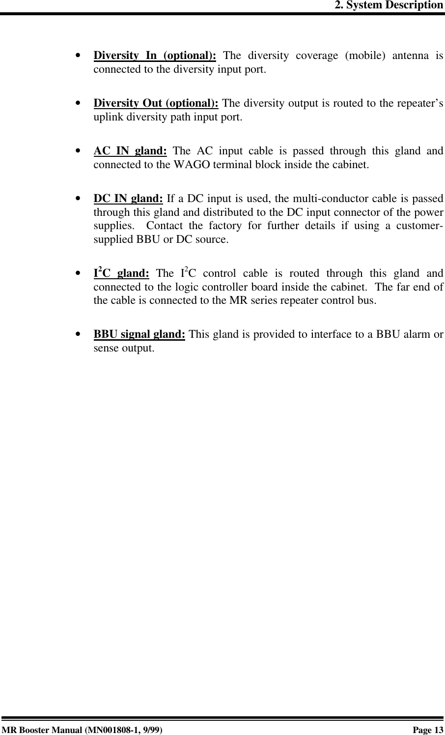
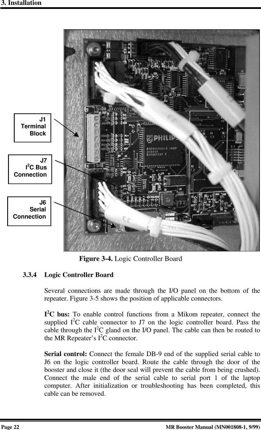
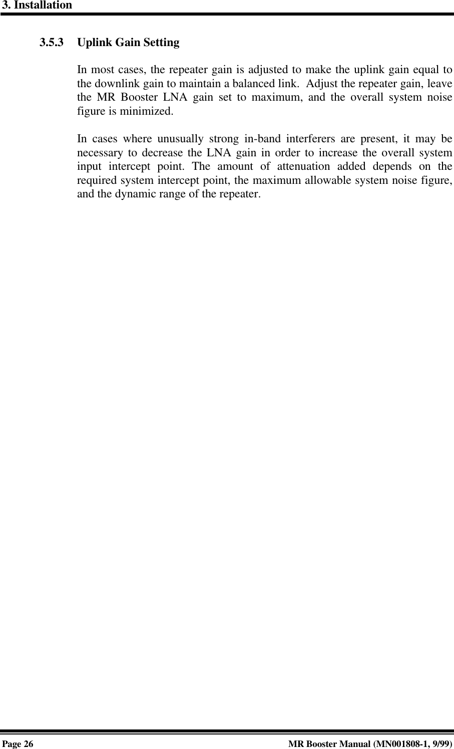
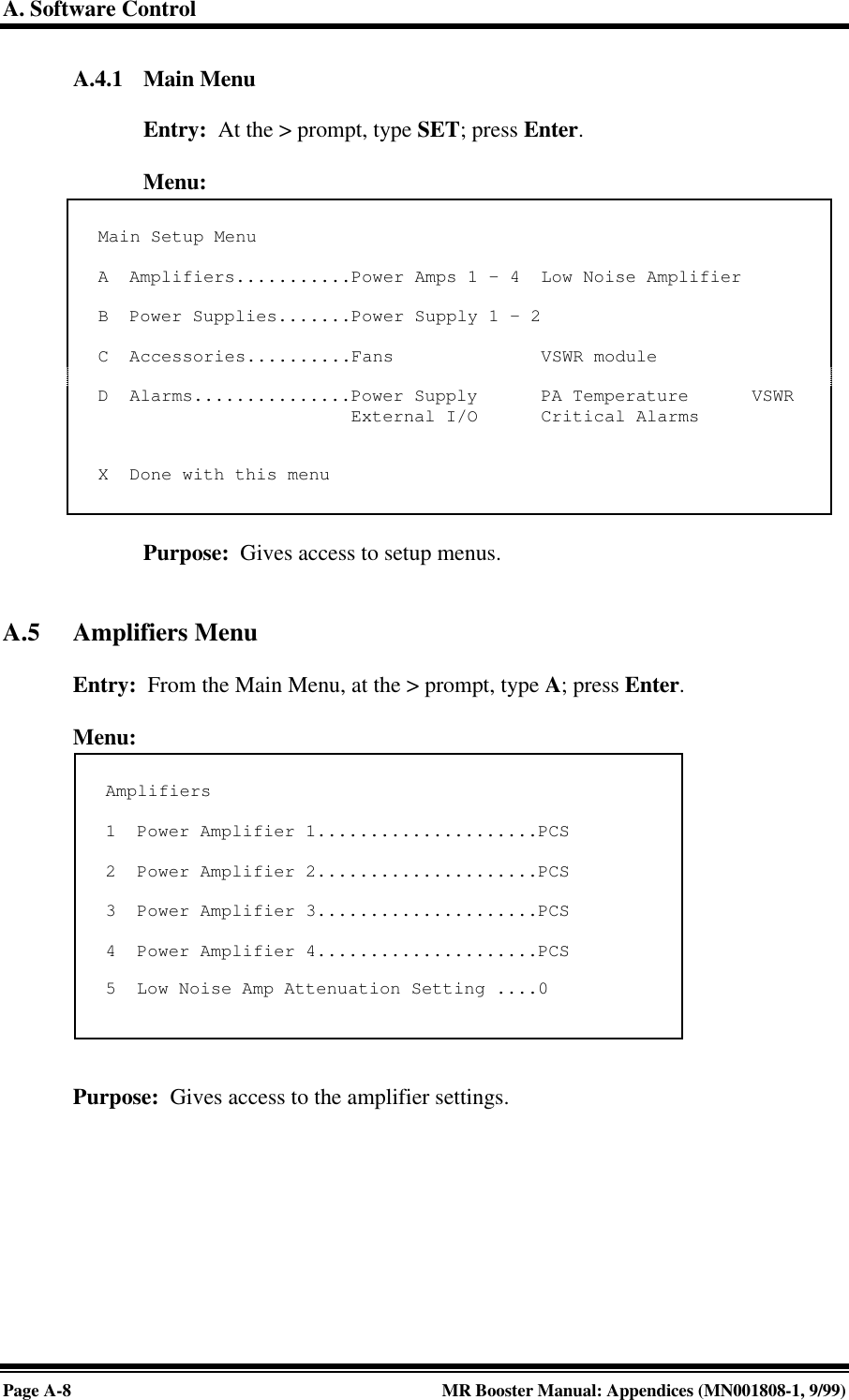
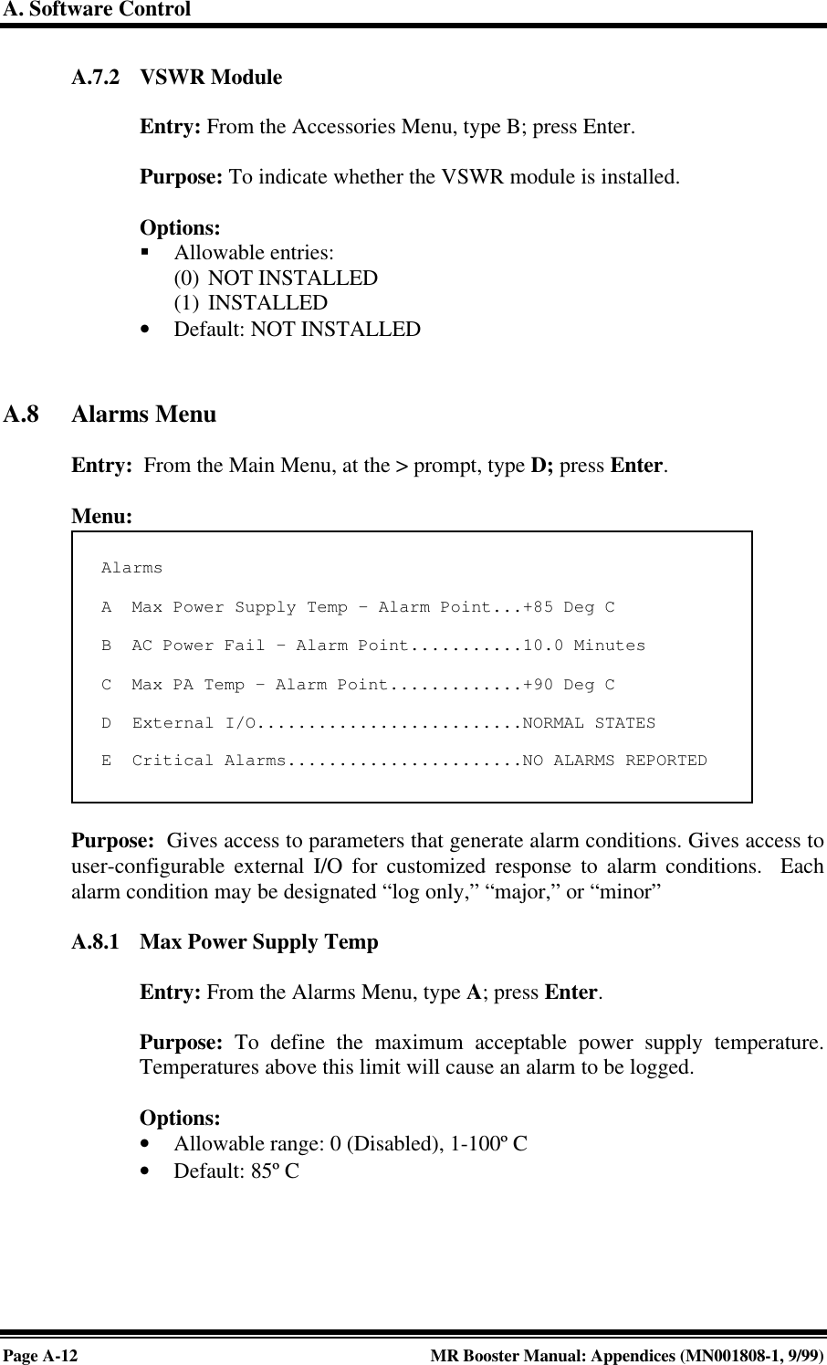
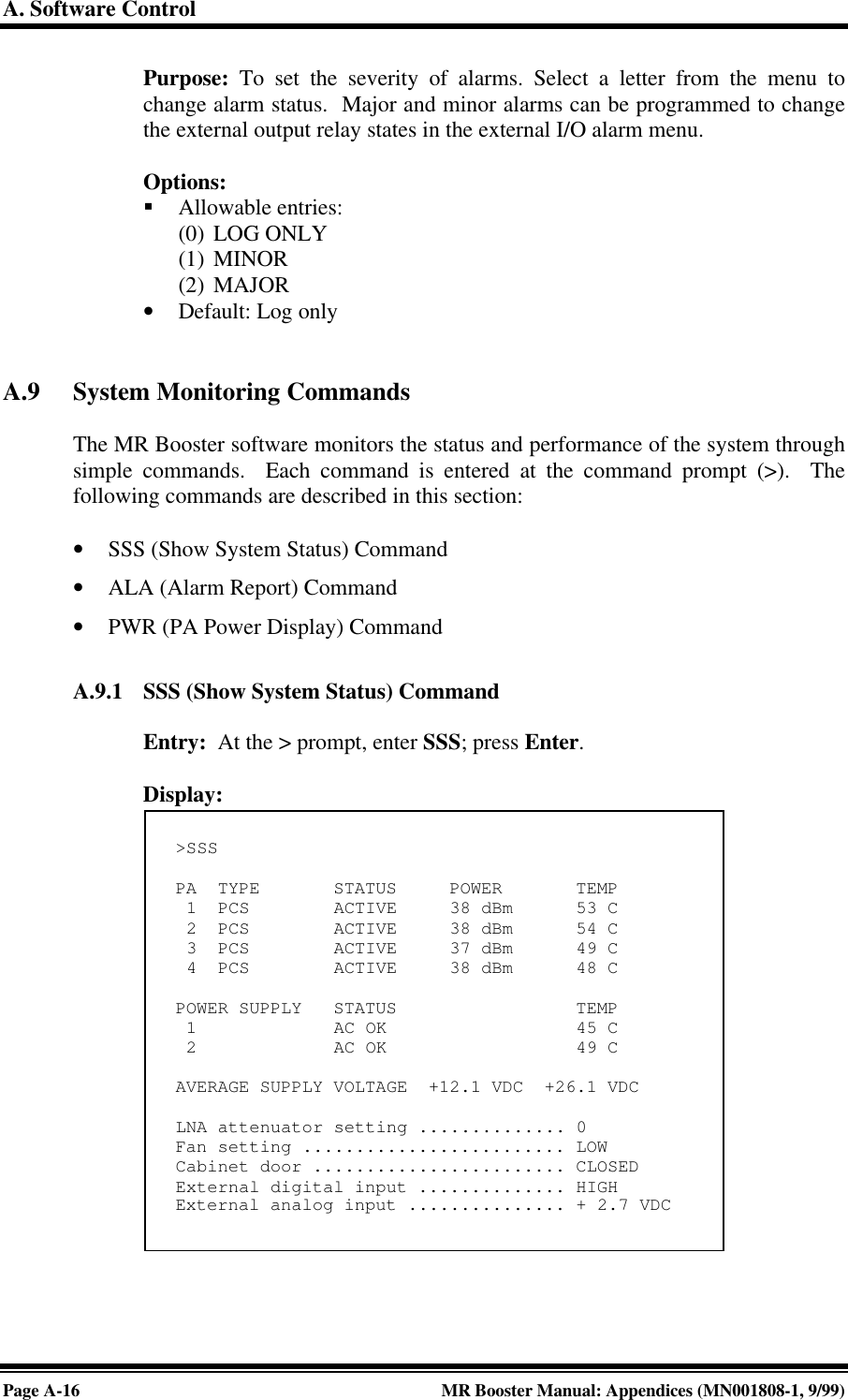
![A. Software ControlPage A-2MR Booster Manual: Appendices (MN001808-1, 9/99)3. Power up the MR Booster. After about two seconds, the terminal should respondwith a welcome message.• If the response is garbled, check the terminal setup.• If there is no response, turn the booster OFF, then ON again. If there is stillno response, turn the unit OFF. Recheck the power hookup and the terminalhookup and configuration.A.3 Basic CommandsFollowing are basic rules and key commands for use with the MR Booster operatingsoftware.Symbol Definition><CTRL><ESC>Command Prompt. The system uses this prompt character to indicateit is ready to accept commands.Control Key. Used in combination with other keys.Escape Key. Escape is a single key marked ESC on most keyboards.Table A-1. Command definitionsA.3.1 SyntaxSystem commands consist of three letters followed by a maximum of threedata fields, as follows:COM [FIELD 1 -] [FIELD 2 =] [FIELD 3] Enter• COM: Three-letter command.• FIELD 1: Up to four hex characters followed by a dash (-).• FIELD 2: Up to four hex characters followed by an equal (=) sign.• FIELD 3: Up to two hex characters.• Enter: Press enter at the end each command.NOTE: Few commands require entry of data fields. After a command hasbeen entered, the system will prompt for data it needs. The system will ignoreunneeded data fields.](https://usermanual.wiki/Andrew-Wireless-Innovations-Group/MRB-LMR/User-Guide-104437-Page-58.png)
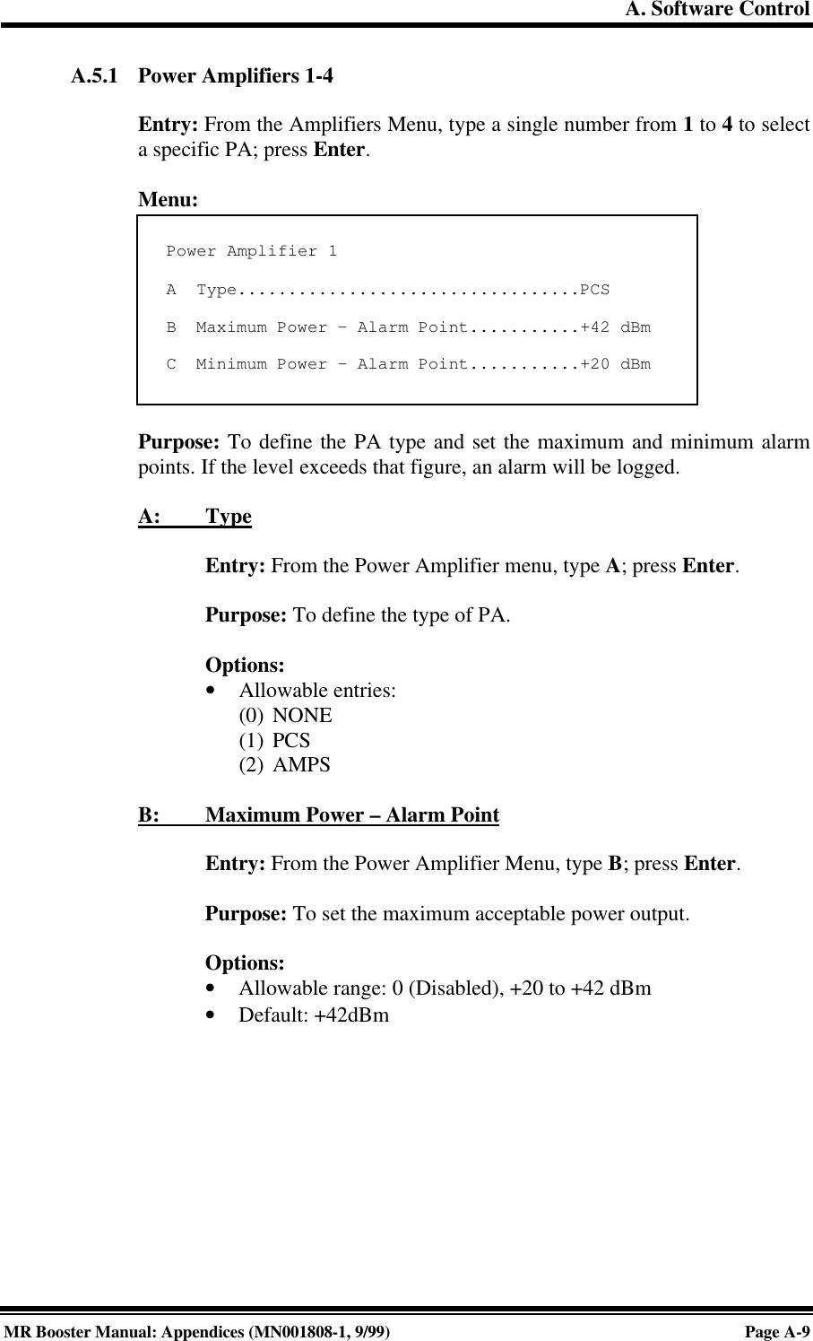
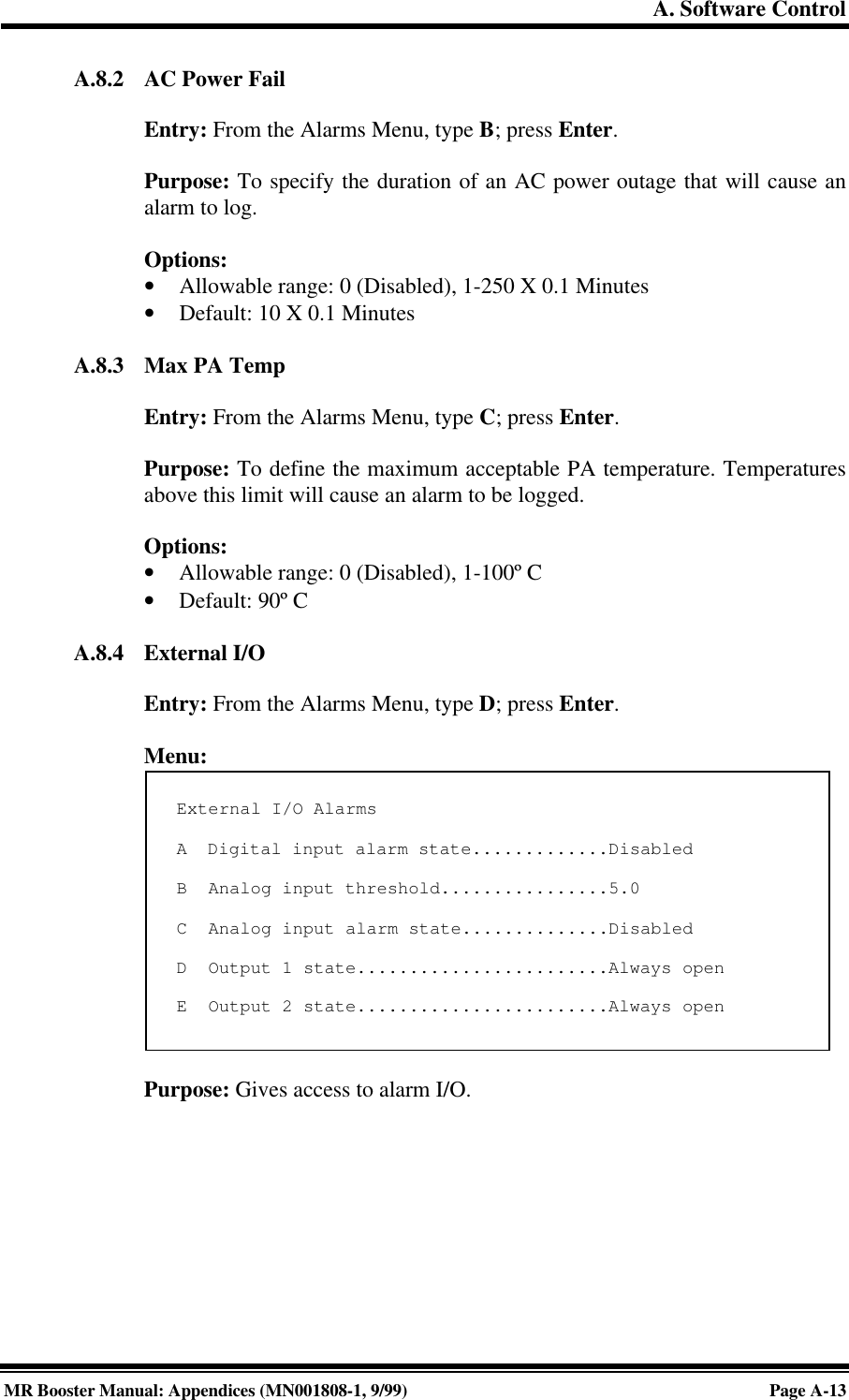
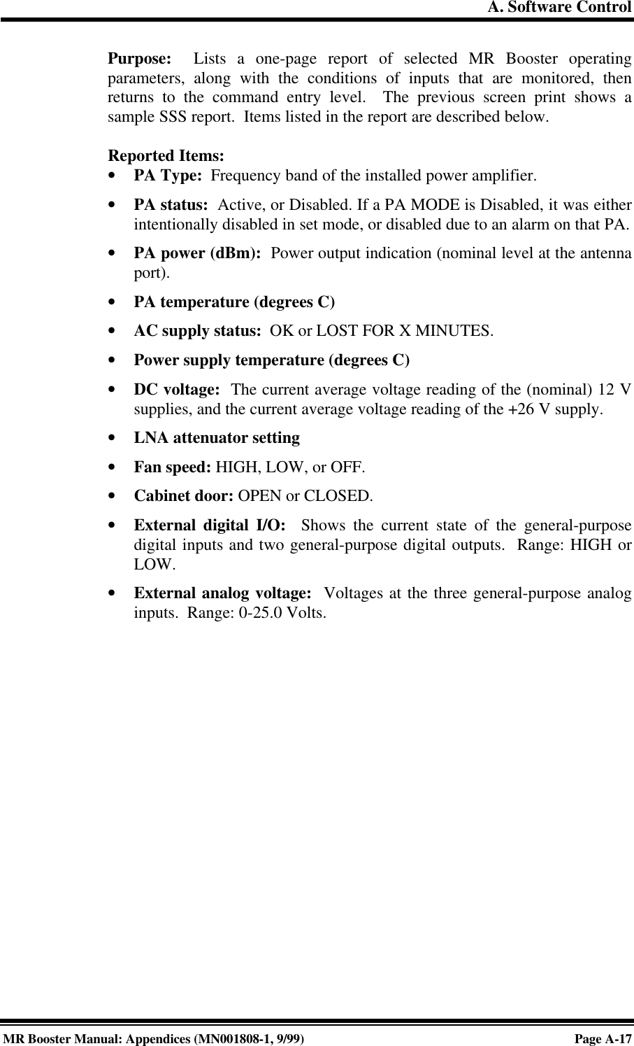
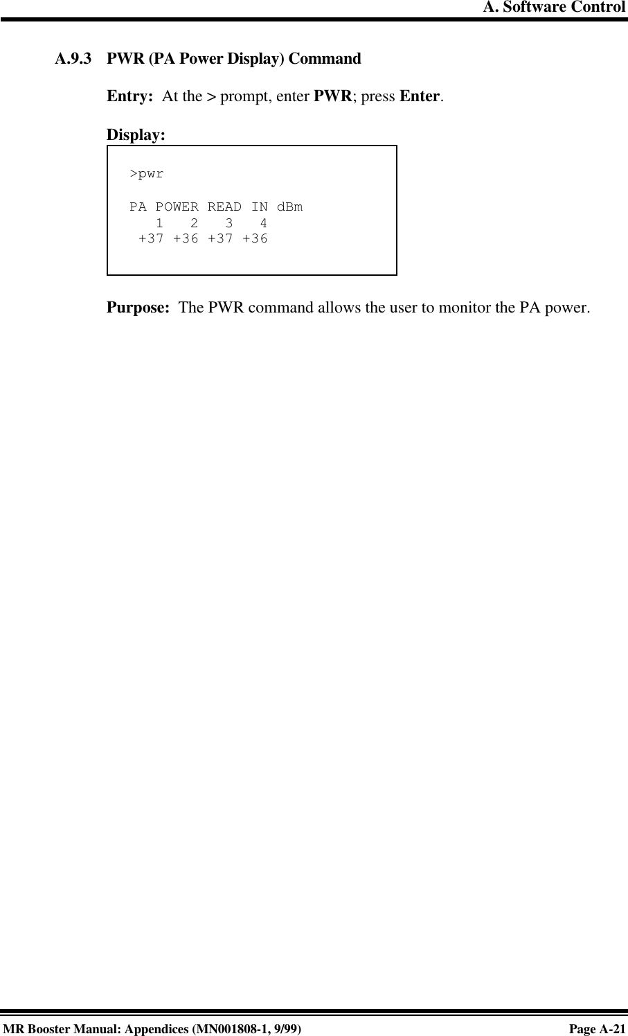
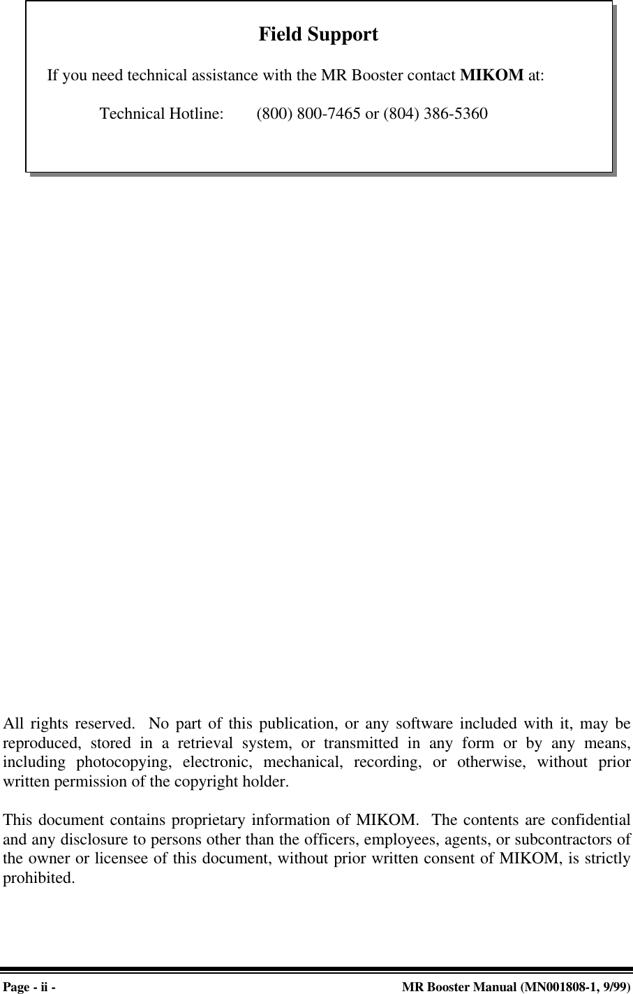
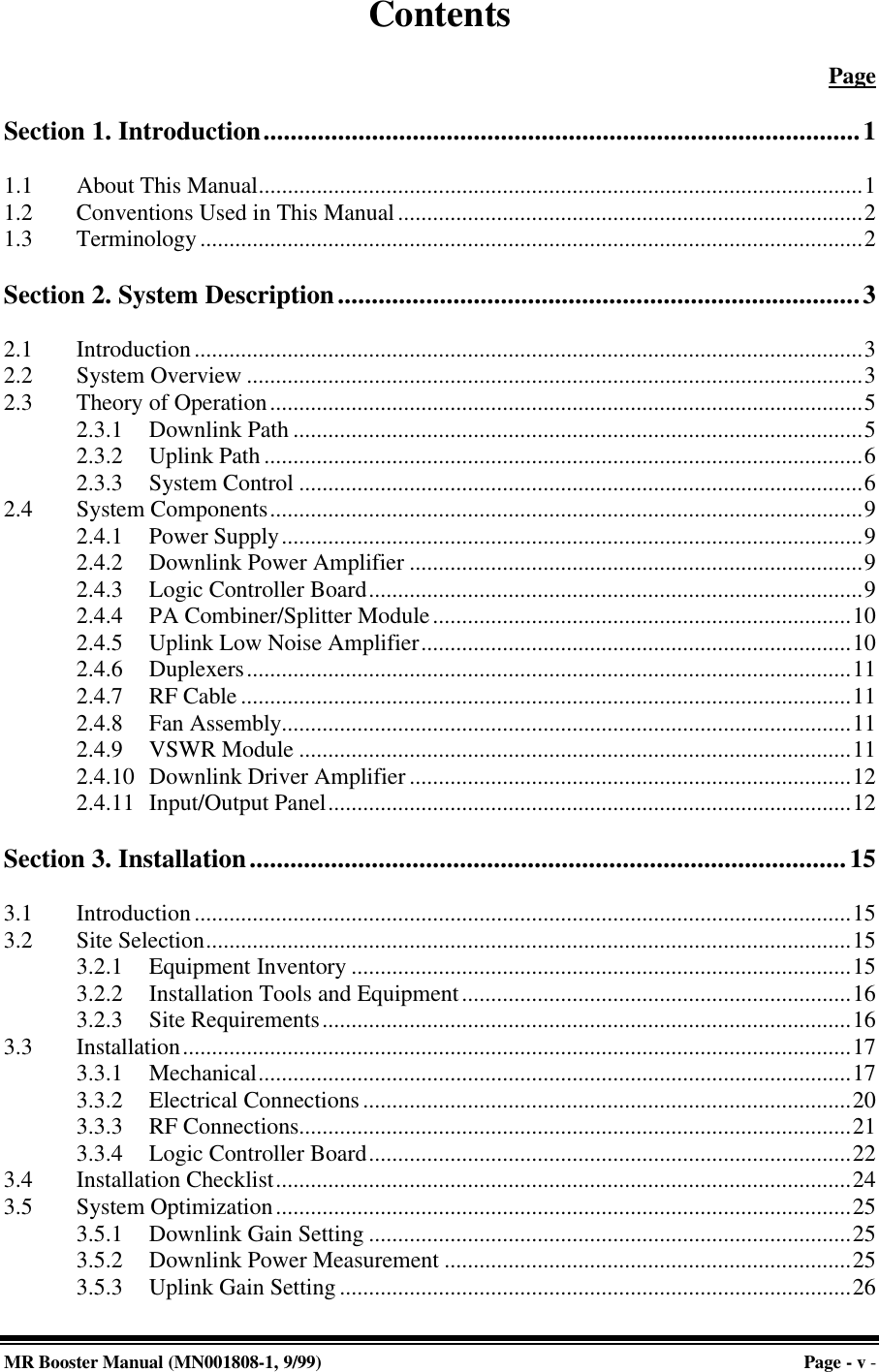
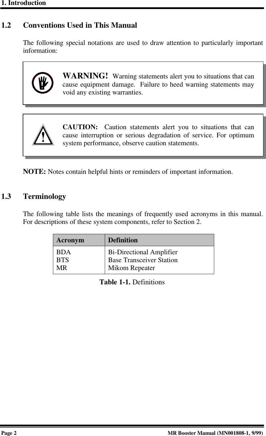
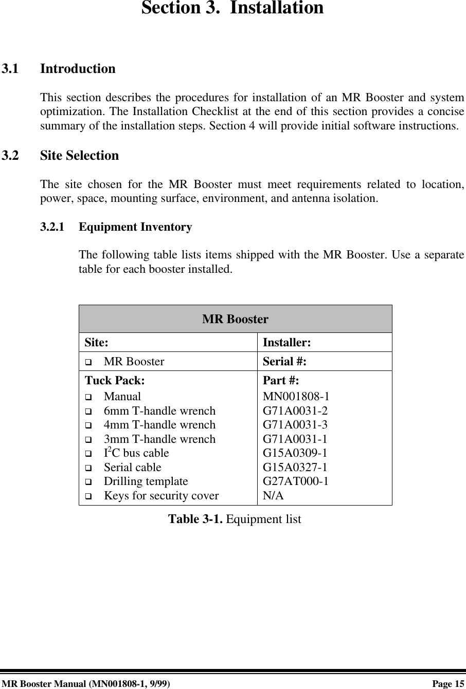
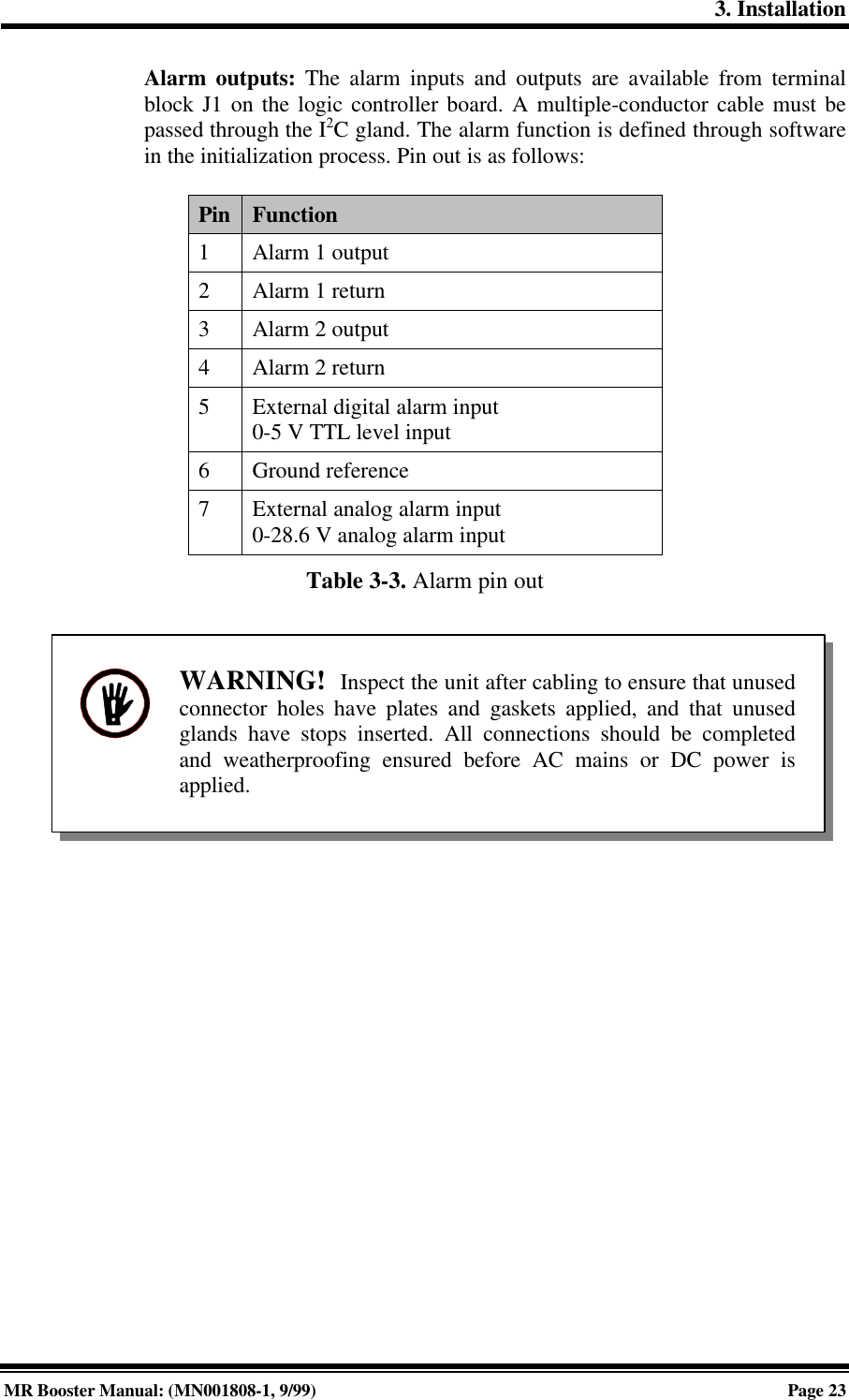
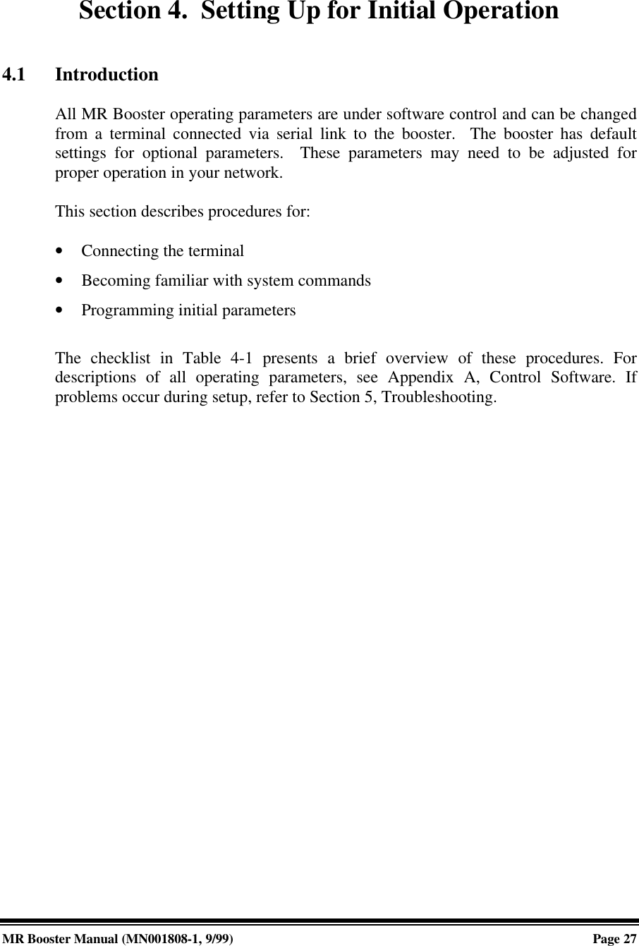
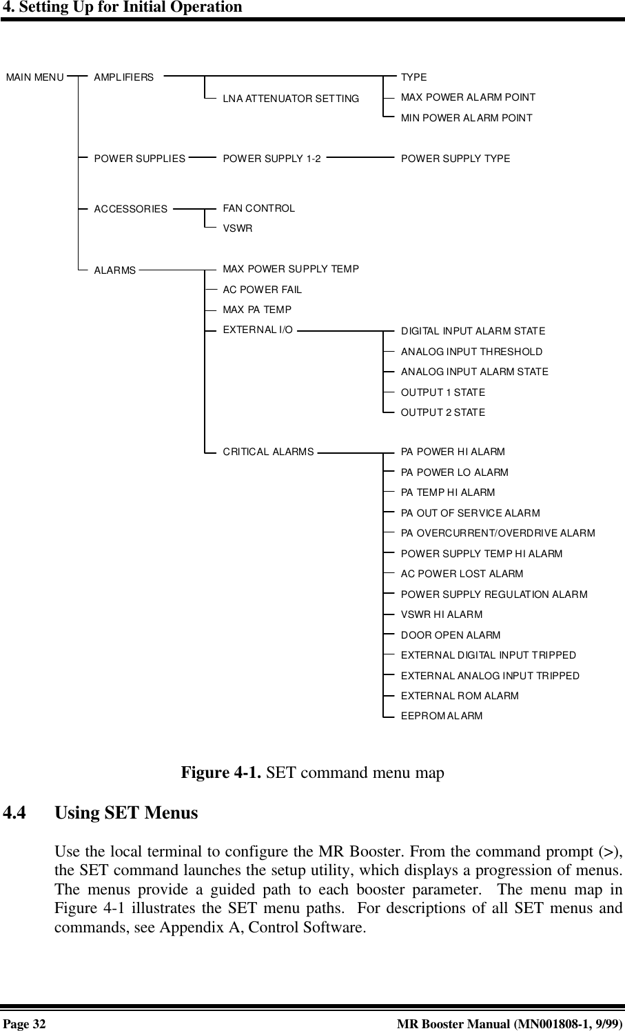
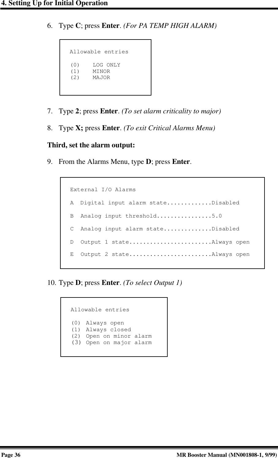
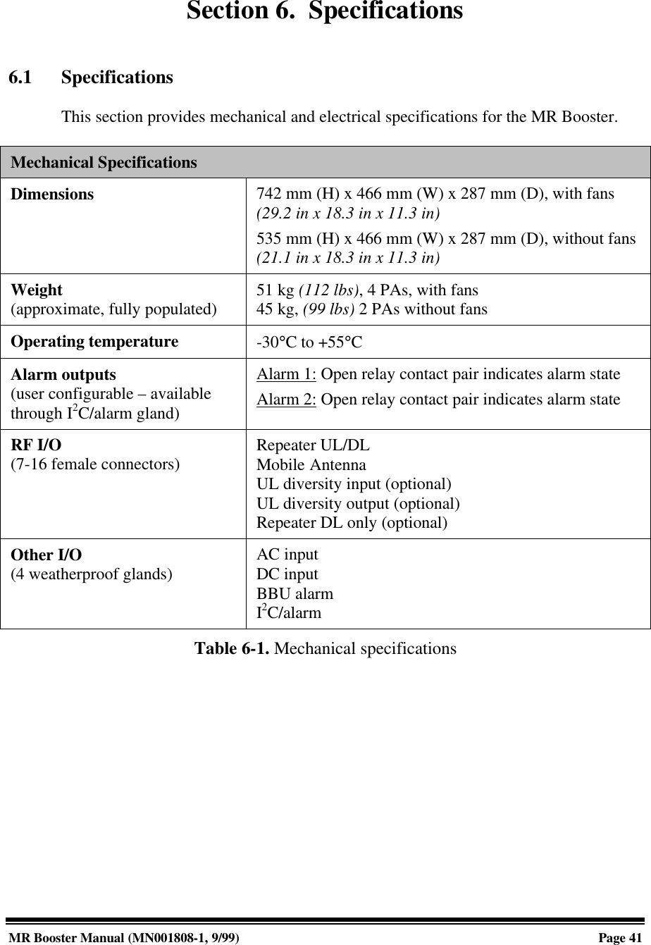
![A. Software ControlPage A-20 MR Booster Manual: Appendices (MN001808-1, 9/99)System Alarm Conditions Reported:• ROM ALARM: Problem in Read Only Memory. (Checked at power-upby computing a ROM checksum and comparing it with a storedchecksum. Note: The CHK command will recompute the ROM checksumand display the stored checksum but will not check for a match.)• EEPROM ALARM: Problem in Nonvolatile Memory. (Checked atpower-up by looking for several "signature bytes" that indicate if datahave ever been written and if gross memory loss has occurred. If thesignature cannot be found, the system tries to write the defaults [and thesignature] to the EEPROM.ü Alarm readings:0 = No problems.1 = Signature not found, but system was able to write itsuccessfully. (All operating parameters will revert to theirdefault values.) Software upgrades usually result in thisreading, since different versions employ different signatures.Repeated occurrences indicate an intermittent EEPROM.• VSWR HIGH ALARM: VSWR is too high in unit with VSWR optioninstalled.• CABINET DOOR OPEN ALARM: This alarm count indicates thenumber of 10-minute intervals during which the cabinet door wasdetected to be open.NOTE: Alarm will not be logged for 30 seconds after an ALA=0 or REScommand. This allows the operator time to disconnect the local terminaland close the door.• GEN PURPOSE ANALOG INPUT ALARM: Indicates the number oftimes the voltage on the general-purpose analog input has gone above orbelow the threshold specified in the Analog Input Alarm State parameter.• GEN PURPOSE DIGITAL INPUT ALARM: Indicates the number oftimes the input has been different from the Digital Input Alarm Stateparameter if enabled.](https://usermanual.wiki/Andrew-Wireless-Innovations-Group/MRB-LMR/User-Guide-104437-Page-76.png)