Andrew Wireless Innovations Group RPT-EAC2100 Broadband PCS repeater User Manual EAC 2100vol Ia
Andrew Wireless Innovations Group Broadband PCS repeater EAC 2100vol Ia
UserManual.wiki
>
Andrew Wireless Innovations Group
>
RPT EAC2100 User Manual
Users manual
Navigation menu
Upload a User Manual
Namespaces
Wiki Guide
HTML
PDF
Info
Views
User Manual
Discussion / Help
Navigation


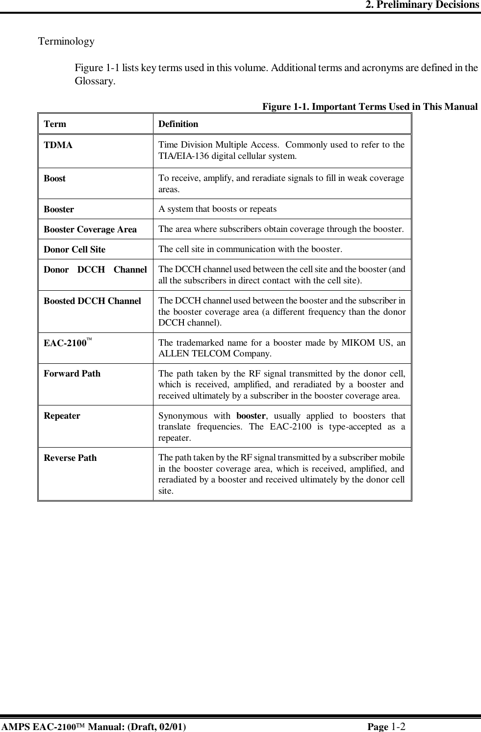


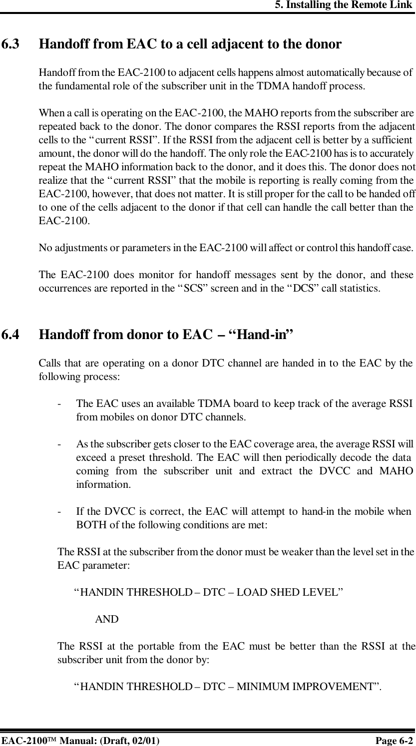
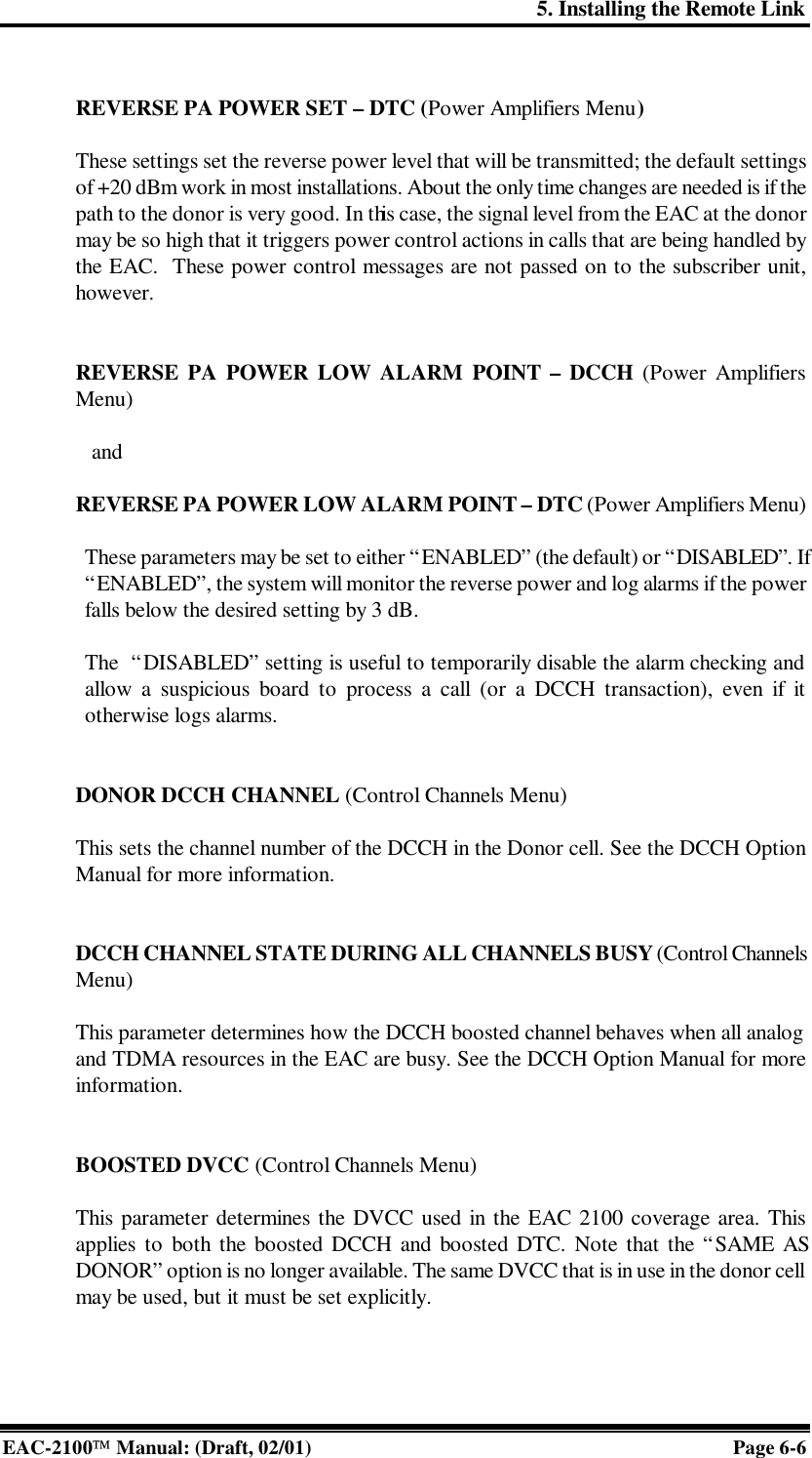
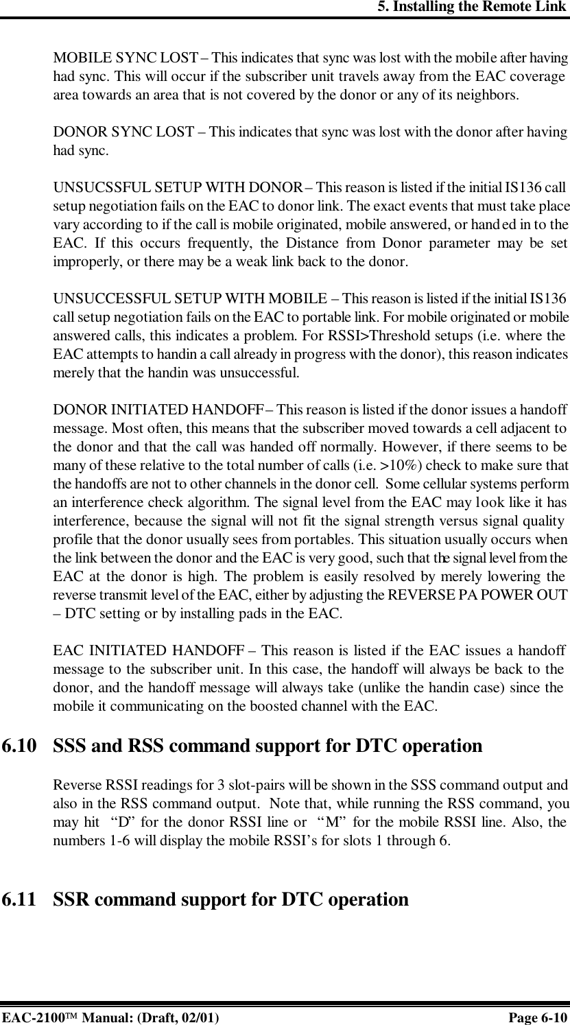
![4. Setting Up for Initial Operation EAC-2100 Manual: (Draft, 02/01) Page 4-6 4.4 Becoming Familiar with System Commands If you are new to EAC-2100 installation, you should use this section to gain familiarity with basic rules for entering commands, as well as key commands that will be used in setting up the system. If you are already familiar with the system, turn to Section 4.6. 4.4.1 Basic Commands Figure 4-5 lists definitions of symbols and abbreviations that are used in this section of the manual. Figure 4-5. Command Definitions Symbol/ Abbreviation Definition > Command entry level. The system uses this prompt character to indicate it is ready to accept commands. <CR> Carriage return or enter. <CTRL> Control. The control key is used in combination with other keys. For example, <CTRL> Z means to hold down the control key while pressing the Z key. ESC Escape. Escape is a single key marked ESC on most keyboards. Syntax. The system responds to commands that consist of three letters followed by up to three data fields, as follows: COM [FIELD 1 -] [FIELD 2 =] [FIELD 3] <CR> In this syntax: • COM is the particular three-letter command. • FIELD 1 consists of up to four hex characters followed by a hyphen (-). • FIELD 2 consists of up to four hex characters followed by an equals (=) sign. • FIELD 3 consists of up to four hex characters. • Each command ends with a carriage return (<CR>).](https://usermanual.wiki/Andrew-Wireless-Innovations-Group/RPT-EAC2100/User-Guide-142401-Page-54.png)
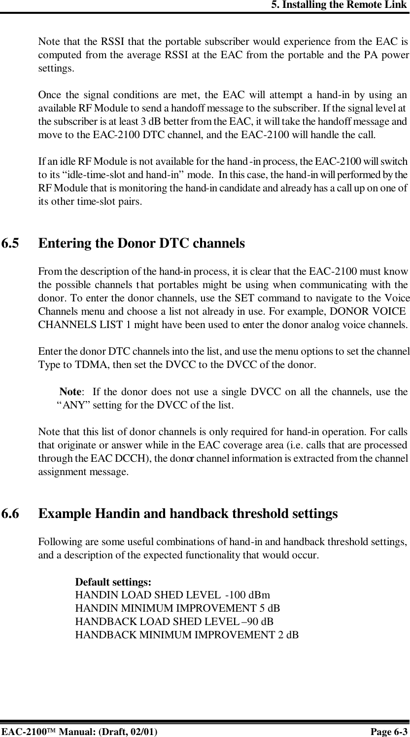
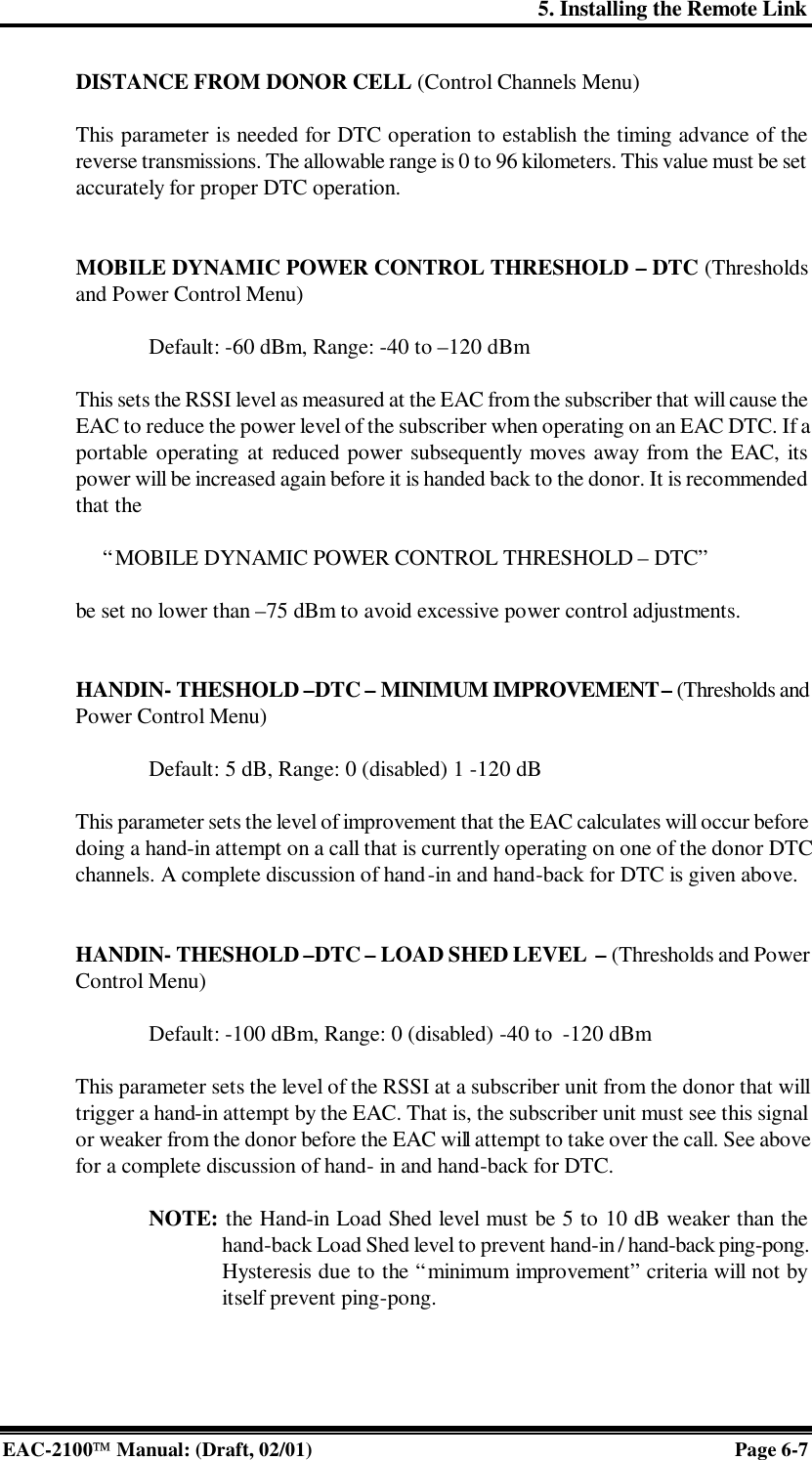
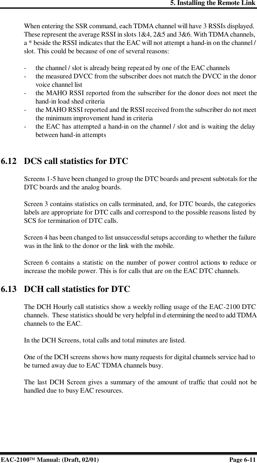
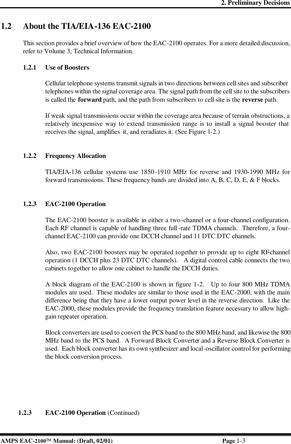
![4. Setting Up for Initial Operation EAC-2100 Manual: (Draft, 02/01) Page 4-16 4.6.6 Setting the Donor DTC Channels (Continued) 3. Enter channels in the list, as described below. A given channel may be entered in only one list. The system will support a maximum of 105 total channels in all four lists (A, B, C, and M). A. To add a channel, type A [channel number] <CR>. B. To add multiple channels, after the A enter multiple channel numbers separated by commas or spaces. If you enter a plus (+) sign before a single channel entry, 15 channels will be added, spaced 21 channels apart, starting with the channel entered. You can then delete extra channels as necessary. C. To remove a channel from the list, type R [channel number] <CR>. D. To remove multiple channels, after the R enter multiple channel numbers separated by commas or spaces. To remove the entire list, type ALL. 4. To return to the DTC Channels Menu, type X <CR>.](https://usermanual.wiki/Andrew-Wireless-Innovations-Group/RPT-EAC2100/User-Guide-142401-Page-64.png)