Andrew Wireless Innovations Group RPT-EAC2100 Broadband PCS repeater User Manual EAC 2100vol Ia
Andrew Wireless Innovations Group Broadband PCS repeater EAC 2100vol Ia
Users manual

TIA-136 DIGITAL
EAC-2100 Manual
- - - D R A F T - - -
Order No. xx-xxx-xx
Issue 02/01
Copyright 2001
All Rights Reserved
HEALTH AND SAFETY WARNINGS
Installer Warning:
Any over-the-air radiated use of this product is intended to be used with either
Roof Top (Building-mount) or Pole Mounted (Non-building-mount) Antennas.
Antenna installation must conform within the following guidelines to meet FCC
RF exposure limits. Otherwise a environmental evaluation is required if:
Narrowband PCS (subpart D): Non-building-mounted antennas: height above ground
level to lowest point of antenna < 10m Radio (Part 24) and total power of all channels >
1000 W ERP (1640 W EIRP).
Building-mounted antennas: Total power of all channels > 1000 W ERP (1640 W EIRP).
Cellular Radiotelephone Service (Part 22, subpart H): Non-building-mounted antennas:
height above ground level to lowest point of antenna < 10m Radio (Part 22) and total
power of all channels > 1000 W ERP (1640 W EIRP).
Building-mounted antennas: Total power of all channels > 1000 W ERP (1640 W EIRP).
For clarification, please refer to FCC rules, 47 CFR ch. I, part 1.1307
F Note: The electrical installation has to be performed in accordance with the safety
regulations of the local authorities. Due to safety reasons, the electrical installation
must be performed by qualified personnel. Subsequent installation, commissioning
and maintenance activities that require the unit to be powered with the cover open
shall only be carried out by suitably qualified personnel.
F Note: The grounding of the Unit has to be performed in accordance with local electrical
codes. A grounding bolt is provided at the bottom of the cabinet in order to connect
the earth bonding cable.
F Note: The Unit weighs 210 lb (95 kg). Make sure that a suitable mounting surface is used
if it is to be wall-mounted, or an adequate floor surface to support the weight is
available if it is to be pedestal-mounted. Also, make sure that adequate lifting tools
are available for placing the unit either on its wall bracket or on the pedestal.

Field Support
If you need technical assistance with the EAC-2100, contact
MIKOM US, an Allen Telecom Company at one of the following
telephone numbers:
Extend-A-Cell HOTLINE: (800) 800-7465
or (804) 386-5340

LIMITED WARRANTY
MIKOM, an ALLEN TELECOM COMPANY, ("ALLEN TELECOM") warrants, on the terms and conditions hereto set forth,
all products manufactured by it to be free under normal use and service from defects in materials and workmanship for a period
of one (1) year from the date of shipment, to the first consumer (the "Warranty Period").
ALLEN TELECOM's obligation under this Limited Warranty is limited to prompt repair or replacement of the product,
at its option, without charge, at an authorized ALLEN TELECOM dealer or at the factory of ALLEN TELECOM in
Forest, Virginia, when the product is returned to an authorized dealer or to the factory with all transportation charges
prepaid and examination of the product shall disclose it to have been defective in the respects aforesaid during the
Warranty Period.
The Limited Warranty shall not be extended beyond its original term with respect to any part or parts repaired or replaced by
ALLEN TELECOM hereunder.
The Warranty Period shall not apply to any product which has been repaired or altered in any manner by anyone other than
ALLEN TELECOM or an authorized outlet of ALLEN TELECOM, or if the defect, malfunction or failure of the product was
caused by damage by lightning, flood or other acts of nature or by power surges, or from unreasonable use, or from improper
installation or application, or to any product which has not been maintained or used in accordance with the operating
specifications set forth in ALLEN TELECOM's written instructions.
IMPLIED WARRANTIES OF MERCHANTABILITY OR FITNESS FOR ANY PARTICULAR PURPOSE ARE
LIMITED IN DURATION TO THE WARRANTY PERIOD SPECIFIED ABOVE.
UNDER NO CIRCUMSTANCES SHALL ALLEN TELECOM BE LIABLE FOR ANY CONSEQUENTIAL
DAMAGES FOR BREACH OF THIS WARRANTY OR OF ANY IMPLIED WARRANTY.
Some states do not allow limitation on how long an implied warranty lasts, so the above limitation may not apply to you.
Some states do not allow the exclusion or limitation of incidental or consequential damages, so the above limitation or
exclusion may not apply to you. This Warranty gives you specific legal rights, and you may also have other rights which
vary from state to state.
ALLEN TELECOM neither assumes nor authorizes any person to assume for it any obligation or liability other than as herein
expressly stated.
1900 MHz
HIGH POWER TRANSLATING CHANNEL SELECTIVE REPEATER
for TIA/EIA-136 PCS Networks
MIKOM’s EAC2100 repeater is designed to provide wide area coverage for TIA/EIA-136, 1900 MHz networks.
High power and gain, achievable due to the intelligent F1 to F2 architecture, allow the EAC2100 to provide
coverage
extension normally available only from macro-
cells. Isolation requirements are also minimized due to the translating
nature of the repeater. The repeater boosts up to four TIA/EIA-
136 carriers with channel selective RF cards. The
EAC2100’s architecture is frequency agile both on the donor and coverage channels.
The EAC2100 uses state of the art DSP technology coupled with a high speed Power PC processor to decode the
TIA/EIA-136 message stream. The EAC2100 fully supports the TIA/EIA-136 Standard and its feature set.
The EAC2100 is software configurable and remotely manageable via a modem dial up link. Call traffic statistics are
logged and reported over a rolling weekly window. All setup parameters are software settable via the local port or dial-
up link. The repeater is designed for easy installation and outdoor use.
•
Frequency Translating Channel Selective
Operation
• 2 or 4 Channel Capacity
• High Forward Output Power
• 12.5 Watts each for 4 Channels
• 25 Watts each for 2 Channels
• Multiple Cabinets for Up to 8 Channels
• Full TIA/EIA-136 Feature Set including:
• Extended Battery Life (sleep mode)
• SMS
• Calling Line and Party ID
• Over the Air Activation
• Authentication
• Registration
• Mobile Assisted Hand Off (MAHO)
• Easy Field Upgrades and Maintenance
• Receive Diversity Standard
1900 MHz
HIGH POWER TRANSLATING CHANNEL SELECTIVE REPEATER
for TIA/EIA-136 PCS Networks
General Specifications
AC Power / Current Requirements
120/240 VAC 50/60 Hz (Auto-ranging)
10A @ 240 VAC
DC Power / Current Requirements
19-30 VDC (nominal 24 VDC)
Maximum 40A @ 27.6 VDC
Standby 10A @ 27.6 VDC
Battery Backup (customer provided)
4 hours typical using 100 AH batteries
Temperature Range
-30°C to +55°C Operating
-40°C to +75°C Storage
Relative Humidity
95% maximum at +50°C
Antenna Connectors
7/16 DIN, N female remote access
Channel Capacity (2 versions available)
2 or 4 RF Channels
Weight 210 lb./ 95 kg
Cabinet Dimensions (H x W x D)
36” x 21.5” x 23”
91 x 55 x 59 cm
RF Specifications
Gain >120 dB (excluding antenna gain)
Channel Bandwidth (TDMA)
Meets TIA-136-280-B BTS requirements
Programmable Frequency Control
Spacing 30 kHz
Bands: BDE, CEF
Channels 1-1999
Output Frequency Accuracy
TIA/EIA-136 synchronized to donor
Minimum Input Donor Signal Level
-75 dBm
Rated Output Power at Antenna Connector
Forward: 25W/ch., 2 channel
12.5W/ch., 4 channel
Reverse: +20 dBm per channel
Sensitivity (Reverse path)
Meets TIA-136-280-B BTS requirements
RSSI Range
Forward: -100 to –20 dBm
Reverse: -120 to –40 dBm
Manufactured under one or more of the following
patents: 4,941,200 / 4,849,963 / 4,754,495
4,704,733 / 5,541,979 and/or patents pending or
applied for in the United States and Canada
The Federal Communications Commission has not
yet approved this device. This device is not, and
may not be, offered for sale or lease, or sold or
leased until the approval of the FCC has been
obtained.

AMPS EAC-2100 Manual: Draft 02/01) Page i
Contents
Page
List of Figures ....................................................................................................................... vi
Quick Start Checklist ........................................................................................................... vii
1. Introduction ............................................................................................................1-1
1.1 About This Volume....................................................................................1-1
1.1.1 Contents ........................................................................................1-1
1.1.2 Terminology..................................................................................1-3
1.2 About the TIA/EIA-136 EAC-2100.......................................................1-4
1.2.1 Use of Boosters.............................................................................1-4
1.2.2 Frequency Allocation ....................................................................1-4
1.2.3 EAC-2100 Operation....................................................................1-4
2. Preliminary Decisions............................................................................................2-1
2.1 Introduction.................................................................................................2-1
2.2 Use of Multi-hop Configuration or Multi-donor Units ......................2-2
2.3 Site Requirements.......................................................................................2-2
2.3.1 Location.........................................................................................2-2
2.3.2 AC Service ....................................................................................2-3
2.3.3 Space .............................................................................................2-3
2.3.4 Mounting Surface..........................................................................2-4
2.4 Antennas .....................................................................................................2-4
2.4.1 Type...............................................................................................2-5
2.4.2 Placement .....................................................................................2-6
2.4.3 Measuring Signal Level and Isolation ..........................................2-9
2.5 Selecting Channels....................................................................................2-11
2.5.1 Identifying the Donor DCCH Channel .......................................2-11
2.5.2 Selecting a Boosted DCCH Channel ..........................................2-12
2.5.3 The Revertive DCCH Channel Option .......................................2-13
2.5.4 The Substitute DCCH Channel...................................................2-13
• Disabling the Substitute DCCH Channel ............................2-14
• Enabling the Substitute DCCH Channel..............................2-14
2.5.5 Selecting the Directed Retry Channels .......................................2-15
2.5.6 Selecting Donor DTC Channels..................................................2-16
2.5.7 Selecting Boosted DTC Channels...............................................2-17

Contents
AMPS EAC-2100 Manual: (Draft, 02/01) Page iii
Page
3. Installing the Hardware ........................................................................................3-1
3.1 Introduction.................................................................................................3-1
3.2 Mechanical Installation ...............................................................................3-4
3.2.1 Uncrating the Equipment..............................................................3-4
3.2.2 Mounting the Cabinet....................................................................3-4
3.2.3 Securing the Doors........................................................................3-5
3.3 Connecting the EAC-2100 to ac Power .....................................................3-6
3.4 Installing the Antennas ...............................................................................3-6
3.4.1 Connecting the Antennas ..............................................................3-7
3.5 Connecting External Alarms/Controls (Optional) .....................................3-8
4. Setting Up for Initial Operation ...........................................................................4-1
4.1 Introduction.................................................................................................4-1
4.2 Powering Up the EAC-2100 ......................................................................4-3
4.3 Powering Down the EAC-2100 .................................................................4-4
4.4 Connecting a Local Terminal......................................................................4-4
4.5 Becoming Familiar with System Commands .............................................4-6
4.5.1 Basic Commands...........................................................................4-6
4.5.2 Using the SET Menus ................................................................ 4-10
4.6 Setting Initial Parameters......................................................................... 4-12
4.6.1 Checking System Status............................................................. 4-12
4.6.2 Entering the Site ID.................................................................... 4-13
4.6.3 Setting the Donor DCCH Channel............................................. 4-14
4.6.4 Setting the Boosted DCCH Channel.......................................... 4-15
4.6.5 Setting the Directed Retry Channels.......................................... 4-15
4.6.6 Setting the Donor DTC Channels.............................................. 4-16
4.6.7 Setting the Boosted DTC Channels ........................................... 4-18
4.6.8 Programming Alarms and Thresholds ....................................... 4-18
4.6.9 Programming the Modem Mobile MIN,
Mobile Power Step, and Passwords ............................. 4-24
4.7 Tuning Transmitter Combiner and Setting Output Power...................... 4-25
4.7.1 Adjusting Combiners and
Power Levels for PAs 1−5 and 7−11 ........................... 4-25
4.7.2 Adjusting the PA 6 Power Level................................................ 4-28
4.7.3 Setting Reverse Path Output Power (If Necessary)................... 4-29
4.7.4 Setting PA Power Low Alarm Points......................................... 4-30
4.7.5 Setting Time and Report Values................................................ 4-31

Contents
AMPS EAC-2100 Manual: (Draft, 02/01) Page iii
Page
5. Installing the Remote Link....................................................................................5-1
5.1 Introduction.................................................................................................5-1
5.2 Setting Up Service .....................................................................................5-3
5.3 Programming the Mobile Radio.................................................................5-4
5.4 Checking Out the Mobile ...........................................................................5-4
5.5 Testing the Remote Link ............................................................................5-5
5.5.1 EAC-2100 Answering ..................................................................5-5
5.5.2 EAC-2100 Originating .................................................................5-6
6. Optimizing Performance ......................................................................................6-1
6.1 Introduction.................................................................................................6-1
6.2 Determining Hand-in and Hand-back Thresholds......................................6-1
6.3 Setting Hand-in and Hand-back Thresholds ..............................................6-2
List of Figures
Figures Page
1-1. Important Terms Used in This Manual....................................................................1-3
1-2. System Operation.....................................................................................................1-5
2-1. Pre-Installation Checklist .........................................................................................2-1
2-2. Recommended Space................................................................................................2-3
2-3 Typical Antenna Installation ....................................................................................2-8
2-4 Antenna Isolation v. Horizontal Separation.............................................................2-9
2-5 Antenna Isolation v. Vertical Separation...............................................................2-10
3-1. Hardware Installation Checklist ...............................................................................3-2
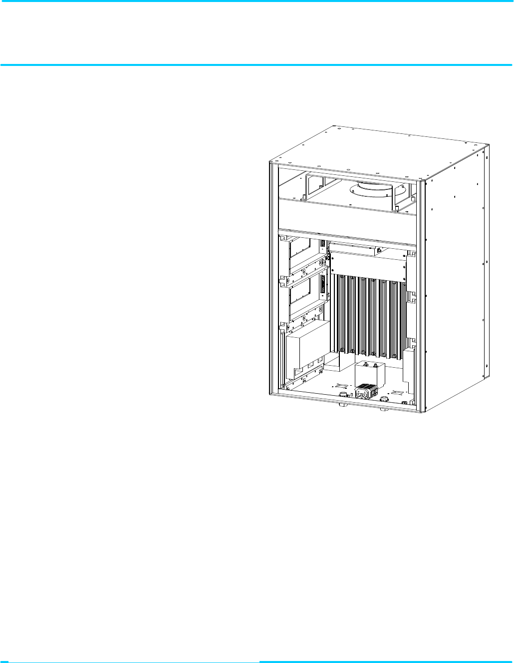
3-2. EAC-2100, Front View (Door Removed)................................................................3-2
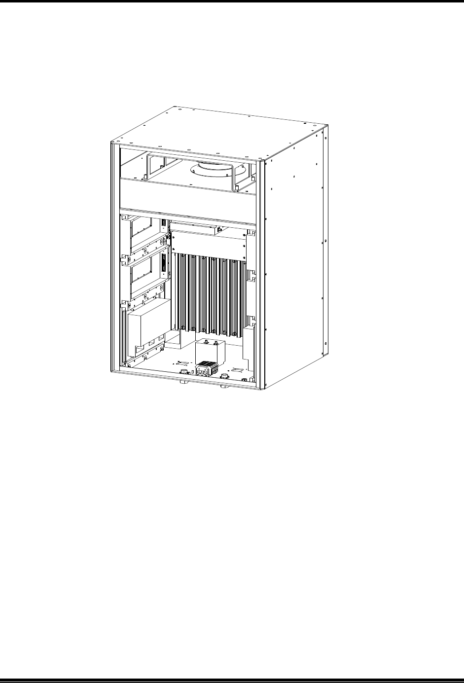
3-3. EAC-2100, Back View (Door Removed) ................................................................3-3
3-4. Outdoor Cabinet Footprint.......................................................................................3-4
3-5. Antenna Connectors.................................................................................................3-7
3-6. External Alarm/Control Connector Pin Out............................................................3-8
3-7. Electrical Specifications for Inputs and Outputs.....................................................3-9
3-8. Typical Wiring for External Inputs and Outputs...................................................3-11
4-1. Setup Checklist.........................................................................................................4-2
4-2. EAC-2100 Breakers .................................................................................................4-3
4-3. Breaker Locations.....................................................................................................4-3
4-4. Location of Local Terminal Connector....................................................................4-4
4-5. Command Definitions ..............................................................................................4-6
4-6. System Commands...................................................................................................4-8
4-7. SET Command Menu Map ....................................................................................4-11
4-8. Combiner Cavity ...................................................................................................4-25
4-9. Location of PA Power Potentiometer.....................................................................4-27
5-1. Remote Link Installation Checklist..........................................................................5-3

Quick Start Checklist
AMPS EAC-2100 Manual: (Draft, 02/01) Page
Programming Initial Parameters (See Sections 4, 5, and 6)
1. Type SSS <CR>. (Nothing should show DISABLED. If anything shows
disabled, refer to Appendix A, Troubleshooting Guide.)
2. Type ALA <CR>. (There should be no alarms. If there are any OUT OF
SERVICE or memory alarms, refer to Appendix A.)
3. Type SET <CR> and go into submenu C, System Parameters.
4. Enter submenu A and program the site ID.
5. Enter submenu B and program the donor and boosted DCCH channels.
Decide how the DCCH control channel is to act when all channels are busy.
6. Enter submenu C and program the boosted DTC RF channel numbers for
channels 2–4.
7. Program the donor DTC RF channels into list.
8. Enter the Modem Control submenu D and program the modem mobile MIN
that has been assigned. Calls made to and from this number will not be
transferred to the booster, but will be trapped-out and handled directly by the
donor. Also set the modem mobile power step to the desired level.
9. Use <CTRL> X to exit the SET menu completely. Press <CR> at the
question prompt.
Continued . . .

Quick Start Checklist
AMPS EAC-2100 Manual: Vol. I, Installation Procedures (27-7655-2, 12/95) Page viii
Programming Initial Parameters (Continued)
12. From the command entry level >, use the TIM command to set the date and
time.
13. From the command entry level >, enter DCS=0, DCH=0, and ALA=0 to reset
the report values.
Completing the Installation
1. Connect the antennas. The unit is now operational!
2. Type SCS <CR> and make some calls. You will see your MIN displayed on
call originations and answers.
3. Connect the handset to the connector on the front of the mobile shelf (see
Section 5).
4. Program hand-in/hand-back thresholds as desired (see Section 6).
5. After completing installation and setup, secure the cabinet door.

2. Preliminary Decisions
AMPS EAC-2100 Manual: (Draft, 02/01) Page 1-1
1. Introduction
1.1 About This Volume
1.1.1 Contents
This volume, pertaining to the TIA/EIA-136 EAC-2100, contains detailed procedures for
installing and operating the EAC-2100. This volume has been divided into a Quick Start
Checklist and 12 sections, described below.
Introductory Information
• Quick Start Checklist: Brief summary of installation and setup procedures.
• Section 1. Introduction: Contents of this volume, key terms, and a general introduction to
the TIA/EIA-136 EAC-2100.
• Section 2. Preliminary Decisions: Factors to consider before you begin installation.
Basic Installation
• Section 3. Installing the Hardware: Procedures for mechanical, electrical, and antenna
installation and connection of external alarms or controls.
• Section 4. Setting Up for Initial Operation: Procedures for powering up the system,
connecting a local terminal, programming parameters, tuning the transmitter combiner, and
setting output power.
• Section 5. Installing the Remote Link: Procedures for setting up, programming, and
checking out the mobile, and testing the remote link.
• Section 6. Optimizing Performance: Procedures for setting hand-back and hand-in
thresholds to optimize booster performance.

2. Preliminary Decisions
AMPS EAC-2100 Manual: (Draft, 02/01) Page 1-2
Terminology
Figure 1-1 lists key terms used in this volume. Additional terms and acronyms are defined in the
Glossary.
Figure 1-1. Important Terms Used in This Manual
Term Definition
TDMA Time Division Multiple Access. Commonly used to refer to the
TIA/EIA-136 digital cellular system.
Boost To receive, amplify, and reradiate signals to fill in weak coverage
areas.
Booster A system that boosts or repeats
Booster Coverage Area The area where subscribers obtain coverage through the booster.
Donor Cell Site The cell site in communication with the booster.
Donor DCCH Channel
The DCCH channel used between the cell site and the booster (and
all the subscribers in direct contact with the cell site).
Boosted DCCH Channel The DCCH channel used between the booster and the subscriber in
the booster coverage area (a different frequency than the donor
DCCH channel).
EAC-2100 The trademarked name for a booster made by MIKOM US, an
ALLEN TELCOM Company.
Forward Path The path taken by the RF signal transmitted by the donor cell,
which is received, amplified, and reradiated by a booster and
received ultimately by a subscriber in the booster coverage area.
Repeater Synonymous with booster, usually applied to boosters that
translate frequencies. The EAC-2100 is type-accepted as a
repeater.
Reverse Path The path taken by the RF signal transmitted by a subscriber mobile
in the booster coverage area, which is received, amplified, and
reradiated by a booster and received ultimately by the donor cell
site.

2. Preliminary Decisions
AMPS EAC-2100 Manual: (Draft, 02/01) Page 1-3
1.2 About the TIA/EIA-136 EAC-2100
This section provides a brief overview of how the EAC-2100 operates. For a more detailed discussion,
refer to Volume 3, Technical Information.
1.2.1 Use of Boosters
Cellular telephone systems transmit signals in two directions between cell sites and subscriber
telephones within the signal coverage area. The signal path from the cell site to the subscribers
is called the forward path, and the path from subscribers to cell site is the reverse path.
If weak signal transmissions occur within the coverage area because of terrain obstructions, a
relatively inexpensive way to extend transmission range is to install a signal booster that
receives the signal, amplifies it, and reradiates it. (See Figure 1-2.)
1.2.2 Frequency Allocation
TIA/EIA-136 cellular systems use 1850-1910 MHz for reverse and 1930-1990 MHz for
forward transmissions. These frequency bands are divided into A, B, C, D, E, & F blocks.
1.2.3 EAC-2100 Operation
The EAC-2100 booster is available in either a two-channel or a four-channel configuration.
Each RF channel is capable of handling three full -rate TDMA channels. Therefore, a four-
channel EAC-2100 can provide one DCCH channel and 11 DTC DTC channels.
Also, two EAC-2100 boosters may be operated together to provide up to eight RF-channel
operation (1 DCCH plus 23 DTC DTC channels). A digital control cable connects the two
cabinets together to allow one cabinet to handle the DCCH duties.
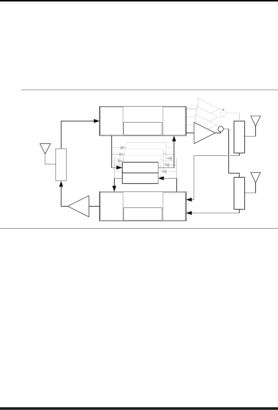
A block diagram of the EAC-2100 is shown in figure 1-2. Up to four 800 MHz TDMA
modules are used. These modules are similar to those used in the EAC-2000, with the main
difference being that they have a lower output power level in the reverse direction. Like the
EAC-2000, these modules provide the frequency translation feature necessary to allow high-
gain repeater operation.
Block converters are used to convert the PCS band to the 800 MHz band, and likewise the 800
MHz band to the PCS band. A Forward Block Converter and a Reverse Block Converter is
used. Each block converter has its own synthesizer and local-oscillator control for performing
the block conversion process.
1.2.3 EAC-2100 Operation (Continued)
2. Preliminary Decisions
AMPS EAC-2100 Manual: (Draft, 02/01) Page 1-4
The Forward Block Converter converts the 1930-1990 MHz signals from the donor cell site to
the 870-890 MHz band. The 870-890 MHz block is fed to the 800 MHz TDMA RF modules
for signal processing. The outputs of the 800 MHz modules are individually converted back to
the 1930-1990 MHz band for subsequent transmission to the repeater coverage area. Since the
PCS band is wider than the 800 MHz tuning range of the 800 MHz RF modules, the Block
Converters cover the PCS band in three 20 MHz segments.
Figure 1-2. System Block Diagram
Likewise, the Reverse Block Converter converts the 1850-1910 MHz signals received from the
subscribers to the 825-845 MHz band. Operation is similar to the Forward Block Converter
except that an RF switching matrix is employed to allow M1/M2 antenna diversity selection.
Another difference is that the reverse signal outputs from the 800 MHz modules are linearly
combined and then up-converted as a group to the 1850-1910 MHz band.
A 50-watt linear PA is used for each forward PCS carrier. The PAs are paired and combined in
two 3-dB hybrid combiners. One hybrid combiner output is connected to the TX port of the M1
duplexer, and the other output is connected to the M2 duplexer.
A 1-Watt composite (20 watts peak) PCS linear power amplifier is used for transmitting the
reverse path signals back to the donor.
The EAC-2100 comes in either a low-split or a high-split configuration. The low-split
configuration covers the A, D and B bands, while the high-split configuration covers the E, F,
and C bands. This is summarized in the table below:
1.2.3 EAC-2100 Operation (Continued)
M1 DUPLEXER
1930-1990
45W
45W
45W
45W
M2 DUPLEXER
800 MHz FWD
800 MHz REV
800 MHz FWD
800 MHz REV
800 MHz FWD
800 MHz REV
TDMA RF MODULES
4-WAY UP-
CONVERTER
4-WAY
DOWN-
CONVERTER
SYNTHESIZER &
L.O.
FORWARD
BLOCK CONV.
4-WAY
COMBINER
& UP-
CONVERTER
DIVERSITY
SWITCH &
4-WAY DWN
CONVERTER
SYNTHESIZER &
L.O.
REVERSE
BLOCK CONV.
DONOR
DUPLEXER
LINEAR
M1 ANT
M2 ANT
DONOR
ANT
1850-1910
1850-1910
1930-1990
870-890
825-845
1930-1990
1850-1910
800 MHz FWD
800 MHz REV

2. Preliminary Decisions
AMPS EAC-2100 Manual: (Draft, 02/01) Page 1-5
Model: Low Split High Split
Band: A, D & B E, F, & C
Channel Number Range: 1-1167 833-1999
Forward Frequency Range: 1930-1965 MHz 1955-1990 MHz
Reverse Frequency Range: 1850-1885 MHz 1875-1910 MHz
Note that there is some overlap between the low split and high split bands. This is due to the
characteristics of the duplexers.
Boosting DCCH Channels. The EAC-2100 monitors the PCS donor DCCH channel to obtain
system-specific information. It generates a DCCH data stream and transmits it on a different
DCCH channel that is assigned for repeater use. Subscribers that are unable to receive the
original channel then lock onto the boosted DCCH channel and communicate with the cell site
through the booster. Adding the repeated DCCH channel to the donor’s neighbor list will allow
subscribers in the repeater coverage area to lock onto the repeater and to receive or place calls.
Boosting DTC Channels. The amplifiers for repeating DTC channels are enabled as needed
when digital traffic channel (DTC) activity is detected in the repeater coverage area. The EAC-
2100 identifies subscribers in the repeater coverage area by two methods: one for identifying
subscribers that place or answer calls from within the repeater coverage area and another for
identifying subscribers that enter the area with a call in progress.
When a call is placed or answered from within the repeater coverage area, the following
sequence occurs:
1. The subscriber accesses the reverse boosted DCCH channel. The EAC-2100 receives the
access, then accesses the reverse donor DCCH channel.
2. The EAC-2100 waits for the corresponding DTC designation message on the forward
channel.
3. The EAC-2100 modifies the DTC designation message by substituting one of its boosted
DTC RF channels for the donor DTC assignment, thus sending the subscriber to one of the
boosted DTC RF channels.
4. A repeat path is set up between the subscriber and the primary donor cell site, with the
subscriber operating on the boosted DTC RF channel, the donor operating on the donor
DTC, and the EAC-2100 translating and boosting between the two.
To identify subscribers that may drive into the boosted coverage area with a call in progress, the
EAC-2100 scans the donor DTC RF channels on a per-time-slot basis and maintains a Received
Signal Strength Indicator (RSSI) average for each time-slot. If the average RSSI exceeds a
preset threshold, the EAC-2100 hands the subscriber to one of the boosted DTC channels.

2. Preliminary Decisions
AMPS EAC-2100 Manual: (Draft, 02/01) Page 1-6
1.2.3 EAC-2100 Operation (Continued)
Boosting to Multiple Donor Cells. To provide for situations in which in-progress calls may be
linked to various neighboring cell sites (multi-donor operation), the system allows for entry of
different donor DTC RF channel lists. For handing in subscribers, note that the donor
antenna system at the EAC-2100 must be specifically designed for multiple donor
operation.
In addition, the MAHO feature of TIA/EIA-136 systems allows the cellular system to hand-off
the subscriber to neighboring cells even if the neighboring cell does not have a propagation path
to the EAC-2100. No additional hardware is required at these neighboring cells. The only
requirement is that these neighboring cells must have their “locate-and-verify” option disabled.
If the booster is adjacent to a single cell site, that cell site is referred to as the donor cell, and the
DCCH channel of that cell site is the donor DCCH channel. The DTC RF channels used in the
donor cell may be entered into the donor DTC channel list with the DVCC of that cell site to
handle subscribers that drive between the donor and booster with a call up.
If the booster is adjacent to several cell sites and there are donor antennas pointing at these cell
sites, the DCCH channel of one of the cell sites is chosen as the donor DCCH channel, and this
cell is then referred to as the primary donor cell. The DTC RF channels of all the neighboring
cells are entered into the scan list with the DVCC of the neighboring cells. Signal strength at
the D1 antenna port must be balanced (to within the cell system hand -off threshold
window) from all neighboring cell sites.
Also, the DCCH channel that is assigned to the EAC-2100 must be included in the DCCH
neighbor list that is sent out by the donor. This is necessary to allow the subscriber to quickly
find the boosted DCCH channel.
Calls placed or answered from within the booster coverage area (identified by decoding the data
streams) are repeated back to the primary donor cell. Calls handed in (identified by channel and
time-slot scanning) are repeated back to the cell on which the call was in progress.
Driving away from the Repeater to The Donor. The EAC-2100 monitors for weak
subscriber RSSI, and also monitors the MAHO information that is being sent back from the
subscriber handset. If the MAHO information indicates that the subscriber is hearing the donor
DCCH channel at an adequate level, then the EAC-2100 will send a hand-off message to that
subscriber to return him to the donor DTC RF channel.
Driving away from the Donor and the Repeater. For this case, the TIA-136 MAHO feature
allows the donor to hand the subscriber to an adjacent cell. The donor determines if the
subscriber is a candidate for hand-off by evaluating the DCCH channel levels in the MAHO list.
If the subscriber is reporting an adjacent DCCH that is stronger than what it is reporting from
the donor DCCH, then the system will issue a hand-off message to that subscriber.
Note that for adjacent cell site handoff to work properly, the system will have to be configured
such that:

2. Preliminary Decisions
AMPS EAC-2100 Manual: (Draft, 02/01) Page 1-7
A. The reverse path signal level from the repeater is set such that it will trigger
MAHO requests from the boosted subscribers,
B. The donor site MAHO list must include all cell sites that are within overlapping
coverage of the repeater, and
C. Those adjacent cell sites that are within overlapping coverage with the repeater
must have any secondary or backup verification feature (such as subscriber locate
and verify before allowing handoff) disabled. Secondary verification may be useful
in a densely populated system where intermod may false the subscriber’s MAHO
readings, but is not necessary in the rural environments for which the EAC-2100 is
intended.
If there is no adjacent cell site to which the donor can direct the subscriber to, then the EAC-
2100 will maintain the boost path for as long as it can.
Ending the Boost. The EAC-2100 will terminate a boosted call under the following conditions:
A. Loss of signal, either from the donor or the subscriber,
B. The subscriber has terminated the call,
C. The land-side or donor has terminated the call, or
D. The EAC-2100 has handed the subscriber to the donor DTC RF channel, or
E. The donor has handed the subscriber (through the boosted DTC RF channel) to an
adjacent cell site.

2. Preliminary Decisions
AMPS EAC-2100 Manual: (Draft, 02/01) Page 1-8

AMPS EAC-2100 Manual: (Draft, 02/01) Page 2-2
2. Preliminary Decisions
2.1 Introduction
Before the EAC-2100 can be installed, preliminary decisions must be made about the following:
• Use of Multi-hop configuration
• Booster site
• Antenna placement
• DCCH and DTC channels to be used
As an installer, you may be involved in some or all of these decisions. The checklist in Figure 2 -1
provides a brief overview of preparations to be made prior to installing the EAC-2100.
Figure 2-1. Pre-Installation Checklist
Checklist
q 1. Coverage area and distance from base station identified. (Sec. 2.3.1)
q 2. Distance to donor entered (in kilometers).
q 2. Electrical service verified for installation site. (Sec. 2.3.2)
q 3. Site selected in accordance with EAC-
2100 weight and space requirements. (Secs.
2.3.3 and 2.3.4)
q 4. M1, M2, D1 and mobile modem antennas selected and installed. (Sec. 2.4)
q Minimum vertical separation of antennas achieved.
q 5. Antenna isolation and signal levels from the cell site measured. (Sec. 2.4.3)
q 6. RF channels selected: (Sec. 2.5)
q Donor DCCH channel
q Boosted DCCH channel
q
Directed retry channels (at least one of the six directed retry channels
should be assigned)

2. Preliminary Decisions
AMPS EAC-2100 Manual: (Draft, 02/01) Page 2-3
2.2 Use of Multi-Hop™ Configuration or Multi-Donor™ Units
Multi-hop operation involves setting up two or more EAC-2100 units to operate together in a line. This
configuration is described in greater detail in Section 7.
Note that no additional equipment is required at neighboring cell sites along the multi-hop path. The
MAHO feature of the TIA/EIA-136 system allows the cellular system to hand off a subscriber from the
EAC-2100 multi-hop coverage area to any neighboring cell.
If either of these arrangements is to be used, system parameters will need to be set accordingly.
2.3 Site Requirements
The site chosen for the EAC-2100 must meet requirements related to location, electrical service, space,
and mounting surface, as described below.
2.3.1 Location
Distance from Donor Cell. If a line-of-sight path between donor cell and booster is maintained
and a high-gain dish antenna is used, the EAC-2100 may be placed up to 92 km away from the
donor cell.
Distance from Antennas. The unit should be placed as close as possible to the antennas to
avoid excessive cable loss. Losses should be kept to 3 dB or less for each antenna cable. In
addition, tower-mounted preamplifiers (TMAs) may be used to improve reverse-path sensitivity.

2. Preliminary Decisions
AMPS EAC-2100 Manual: (Draft, 02/01) Page 2-4
2.3.2 AC Mains Service
The following AC mains service is required:
• 120/240 VAC
• single-phase
• 20-amp minimum service
2.3.3 Space
The EAC-2100 unit is approximately 22 in (W) x 23 in (D) x 36 in (H) (56 cm x 59 cm x 91
cm). If it is mounted on a wall bracket, allow an additional 3 in (8 cm) depth. For wall mounted
applications, it is recommended the bottom of the cabinet should be at least 12 in (31 cm) above
the ground or floor. This will allow easy access to the RF connectors that are on the bottom of
the cabinet.
If it is to be mounted on the optional pedestal, allow an additional 12 in (31 cm) to the overall
height. Approximately 3 in (8 cm) space must be provided between the rear of the cabinet and
any obstructing surface, such as a wall. This is necessary to prevent blocking the heat-
exchanger outlet vent. Also, provide enough space on of the two sides to allow access to the
antenna connectors underneath the cabinet. This access will be through one of the two filter
openings. Enough space should be provided on the other side to allow the filter to be removed
and cleaned. Six inches (15 cm) should be adequate for this purpose.
Finally, allow enough space on the front to allow the door to be fully opened (2 ft, or 60 cm
minimum).
Figure 2-2. Recommended Space
Put updated 3D drawing showing the door, the pedestal, the hanging bracket, and dimensions here.
2. Preliminary Decisions
AMPS EAC-2100 Manual: (Draft, 02/01) Page 2-5

2. Preliminary Decisions
AMPS EAC-2100 Manual: (Draft, 02/01) Page 2-6
2.3.4 Mounting Surface
If the wall hanging bracket is used, make sure that the wall construction and the fastening
hardware is adequate for handling at least the 210 lb (95 kg) of the EAC-2100.
If the pedestal mount is to be used, make sure that the floor or concrete surface is adequate for
handling approximately 60 pounds per square foot (300 kg per square meter). The pedestal has
mounting holes to allow it to be bolted to the floor. Bolting to a surface should be done before
the EAC-2100 is placed on the pedestal.
The EAC-2100 may be mounted either indoors or outside. If it is mounted outside, adequate
drainage away from the pad should be provided to prevent water from accumulating underneath
the cabinet.
2.4 Antennas
The EAC-2100 requires four antennas:
D1 antenna: Primary antenna facing donor cell site(s), used for:
• Reception of DCCH and DTC channel signals from donor cell site(s).
• Transmission of DCCH and DTC signals back to cell site(s).
M1 antenna: Primary antenna facing subscribers in the booster coverage area, used for:
• Transmission of boosted DCCH channel and boosted DTC channels to subscribers.
• Diversity reception from subscribers.
• Transmission of hand-back messages to subscribers.
M2 antenna: Second antenna facing subscribers in the booster coverage area, used for:
• Sending hand-in and grab-back messages to subscribers.
• Diversity reception from subscribers.
• Sending data messages to multi-hop EAC-2100s and Multi-Donor Units.
Data mobile antenna (optional): Antenna for the installed cellular mobile. Used for:
• Receiving and transmitting signals from any cell site in the system.
• In many cases the internal data mobile may be connected to the test port on the donor duplexer. This
will allow the data mobile to share the donor antenna for its link back to the donor base station.
Ensure that the proper antenna type and placement have been selected for each antenna.

2. Preliminary Decisions
AMPS EAC-2100 Manual: (Draft, 02/01) Page 2-7
2.4.1 Type
The antennas for the booster area should be chosen by the same criteria as used for a cell site. A
typical installation might use the following antennas:
D1: One high-gain directional antenna pointed toward the donor cell.
M1 and M2: Two identical directional or omnidirectional antennas.
F NOTE: Regardless of the type of antenna chosen, the M1 and M2 antennas must have
identical gain and patterns, and be installed to cover the same area.
Mobile: A low-gain or YAGI base station antenna. Alternatively, a coupler port on the donor
duplexer may be used to share the data mobile with the donor antenna.

2. Preliminary Decisions
AMPS EAC-2100 Manual: (Draft, 02/01) Page 2-8
2.4.2 Placement
Requirements. Antenna locations must meet the following requirements for minimum signal
level, physical separation, and isolation.
• Minimum Signal Level: The minimum signal level from any cell to be used as a donor
must be -75 dBm at the D1 antenna connector on the EAC-2100. The minimum signal level
from the donor cell must be at least -100 dBm at the data mobile antenna feed.
• Physical Separation: For diversity operation, the M1 and M2 antennas should be
physically separated by at least 10 feet (3 m) horizontally or 3 feet (1 m) vertically.
F NOTE: Even if diversity reception is not required, both the M1 and M2 antennas
must be installed, since both antennas are used to transmit to the boosted
subscribers.
Multi-hop configurations: An EAC-
2100 not adjacent to the donor
requires a forward signal level of at least -
70 dBm (at the D1 antenna
connector) from the previous EAC-
2100 in the chain. Each booster
along the path must be able to communicate only with the previous
and next booster. They are not required to be able to receive from or
transmit back to the donor cell site.

2. Preliminary Decisions
AMPS EAC-2100 Manual: (Draft, 02/01) Page 2-9
2.4.2 Placement (Continued)
• Isolation: Isolation between the D1 and M1 and between the D1 and M2 antennas must be
at least 75 dB. Isolation between the mobile antenna and all of the others must be at least 60
dB.
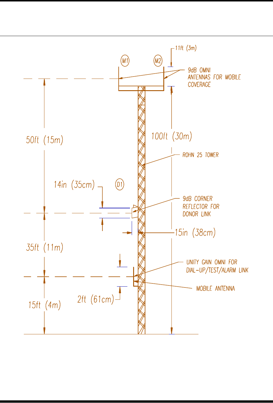
Figure 2-3 shows a typical installation. M1 and M2 are placed highest on the tower to
achieve the best coverage to the boosted area. D1 is placed below M1 and M2. At least 25
feet (8 m) of vertical separation is usually needed to meet the isolation requirement.
F NOTE: The isolation achieved at a given separation will vary greatly depending
upon the type of antennas, nearby reflections, etc. Twenty-five feet (8 m) vertical
separation may not be enough in all cases.
D1 must be placed high enough to receive the required minimum signal level from the
donor. The data mobile antenna can usually be placed close to the ground. At least 15 feet
(5 m) vertical separation between the data mobile antenna and the others is usually needed,
however, more may be required in some installations.
2. Preliminary Decisions
AMPS EAC-2100 Manual: (Draft, 02/01) Page 2-10
2.4.2 Placement (Continued)
Figure 2-3. Typical Antenna Installation

2. Preliminary Decisions
AMPS EAC-2100 Manual: (Draft, 02/01) Page 2-11
2.4.3 Measuring Signal Level and Isolation
To verify the correct placement and alignment of the antennas, it will be necessary to measure
the signal level from the donor cell site (on the selected donor DCCH channel) and the isolation
between the various antennas to ensure they meet the required levels.
To measure the donor DCCH signal level:
• Connect a communications service monitor or some other frequency selective measuring
instrument to the D1 antenna; monitor the DCCH channel from the donor cell;
• Adjust the orientation of the D1 antenna to peak this reading; at least -75 dBm is required.
To measure antenna isolation:
Antenna isolation can be measured using a spectrum analyzer and a tracking generator. These
functions are often combined in cellular communications monitors.
The tracking generator output is applied to the coax connector going to one of the system
antennas, while the spectrum analyzer input is connected to one of the other system antennas.
The tracking generator output level should be set to maximum (usually about 0 dBm), with the
spectrum analyzer set to check both the transmit and receive ends of the band. If a 0 dBm signal
is used as the source, the dBm reading on the analyzer will be equal to the amount of isolation
achieved between the two antennas.
F NOTE: Isolation is usually frequency dependent, with several nulls and peaks possible
in each band. The highest peak in either band defines t he minimum isolation that is
achieved with a particular antenna installation.

2. Preliminary Decisions
AMPS EAC-2100 Manual: (Draft, 02/01) Page 2-12
2.4.3 Measuring Signal Level and Isolation (Continued)
Signals from the cellular system will likely be stronger than the sweep signal received from the
tracking generator, and difficulty may be experienced in measuring the actual isolation.
Many spectrum analyzers have difficulty reading signals below -60 to -70 dBm when sweeping
a broad bandwidth. In this case, the band may be swept in smaller frequency segments, or a
separate signal generator with higher possible output power may be substituted for the tracking
generator. The signal generator frequency and amplitude can be manually changed to avoid
conflict with existing strong signals from the donor and other cell sites.
The signal generator should be manually swept through both the low split and the high split
bands to determine the minimum isolation point.
To measure isolation:
1. Supply a known signal level of about 0 to +20 dBm across the band into one of the antenna
feeds (M1, D1, or mobile).
2. Using test equipment, measure the signal level received on the other antenna feeds.
3. Adjust antenna locations and orientations to achieve the desired antenna isolations.
4. Move the signal source to other antennas, and recheck the isolation. Be sure to check both
the forward and the reverse bands.
5. If the D1 antenna has been repositioned, recheck the received donor DCCH channel signal
level to verify that it exceeds -75 dBm.
6. Record these measurements.
Refer to Appendix B for a more detailed procedure for measuring isolation.

2. Preliminary Decisions
AMPS EAC-2100 Manual: (Draft, 02/01) Page 2-13
2.5 Selecting Channels
Before beginning to install the hardware, identify the various channels on which the system will operate:
• DCCH channel
• Boosted DCCH channel
• Donor DTC RF channels (primary and neighboring)
• Boosted DTC RF channels
• Directed retry channels
Make note of all selected channels. They will be entered as system parameters during installation
(Volume 1, Section 4). DCCH channel parameters are listed under the DCCH Channels Menu, shown
here with all available selections. Refer to this menu for sections 2.5.1 through 2.5.5.
(NOTE: SETTING OF THE BOOSTED DCCH HAS BEEN MOVED FROM THIS MENU TO THE RF BOARDS MENU.
SHOULDN’T THE DONOR AND BOOSTED DCCH CHANNEL ASSGINEMENTS BE IN THE SAME MENU?)
2.5.1 Identifying the Donor DCCH Channel
The donor DCCH channel (selection I, Control Channels Menu) is the control channel of the
primary cell site with which the EAC-2100 will communicate.
• When the booster is adjacent to a single cell site, the DCCH channel of that cell site is
the donor DCCH channel.
• When the booster is adjacent to several cell sites, the DCCH channel of the cell site with
the most unused channels should be chosen. (This cell is then referred to as the primary
donor cell.) Signals from multiple (primary and secondary) donors must be balanced at the
EAC-2100 donor antenna be to within the handoff hysteresis window that is programmed
into the donor cells. Otherwise, unwanted hand-offs by the cellular system may occur,
thereby causing dropped calls.
Control Channels Menu
Default Values
C Directed Retry Channels ............................ LIST
D Back-up DCCH Channel Option ...................…..DISABLED
E Revertive DCCH Channel Option. . . . . . . . . . .DISABLED
I Donor DCCH Channel ................................. 319
J DCCH Channel State During "All Channels Busy" ...... DIRECTED RETRY
K BOOSTED DVCC .....................................…..11
L Distance from Donor Cell .........................…..1 km

2. Preliminary Decisions
AMPS EAC-2100 Manual: (Draft, 02/01) Page 2-14
2.5.2 Selecting a Boosted DCCH Channel
The boosted DCCH channel (Selection 1-4, RF boards menu) is the control channel that will be
used in the EAC-2100 coverage area. Select a channel that meets the following requirements:
• Must conform to the DCCH channel plan for the system with which it is to work:
• Must be included in the neighbor list of its donor cell site and any neighbor cells that may
be in range of the EAC-2100
o The boosted DCCH channel may be entered into the switch either as a
phantom cell or as a border cell.
o A DCCH channel that is assigned to a cell site elsewhere in the system should
not be “borrowed” as a boosted DCCH channel for the EAC-2100 unless the
system has the ability to segregate operational areas. Otherwise, subscribers
operating through the EAC-2100 may be viewed by the system as a potential
hand-off candidate to the cell from which the DCCH assignment was
“borrowed”, even if the subscriber is many miles away from that cell.
• Must be different from the DCCH and DTC RF channels used in cells adjacent to the EAC-
2100 to avoid interference.
2.5.3 The Revertive DCCH Channel Option
When the Revertive DCCH Channel Option (selection E, DCCH Channels Menu) is enabled,
the EAC-2100 continues to repeat the DCCH channel (forward and reverse) when all of the
normal DTC channels become occupied. If another call goes through, the DCCH channel
equipment is redesignated to operate as DTC only, and the last candidate is assigned to and
boosted by the DCCH channel equipment. If the DCCH channel has a DTC call up on either or
both of its available DTC channels, then the revertive operation will be inhibited. Only when no
DTC channels are being boosted on the DCCH channel will the EAC-2100 temporarily reassign
the DCCH channel for DTC-only service.
When the call on the temporarily reassigned DCCH channel ends, the equipment reverts to
repeating the DCCH channel. If another DTC RF channel becomes free (no calls on any of its
time slots), then the EAC-2100 will hand-off the subscriber(s) operating on the DCCH channel
equipment to the newly available DTC RF channel equipment (this is referred to as call
transfer). The DCCH channel equipment then reverts to repeating the DCCH channel.
F There must be at least a 3-channel spacing between any boosted
channel and any donor channel.

2. Preliminary Decisions
AMPS EAC-2100 Manual: (Draft, 02/01) Page 2-15
2.5.4 Selecting the Directed Retry Channels
The Directed Retry Channels parameter (selection C, Control Channels Menu) is probably the
best option for most EAC-2100 installations. The parameter is a factory-set default and is one
of four options available under selection J (DCCH Channel State During "All Channels Busy")
of the Control Channels Menu.
When the EAC-2100 is busy, the boosted DCCH channel (or substitute DCCH channel, if
Revertive DCCH Channel Option is enabled) remains on the air. If more accesses or page
responses come in, the EAC-2100 sends the subscriber a special "directed retry" message. This
message gives the subscriber a list of up to six other DCCH channels on which to attempt the
access. These are the directed retry channels and are assigned by the customer (selection C,
Control Channels Menu).
The list of six channels is sent to the subscriber in the directed retry message. The subscriber
will scan this set of channels and try its access on the strongest of the six channels.
F NOTE: The donor DCCH channel and the DCCH channels of cells adjacent to the
boosted coverage area should be entered. The boosted DCCH channel must not be in
this list.

2. Preliminary Decisions
AMPS EAC-2100 Manual: (Draft, 02/01) Page 2-16
2.5.5 Selecting Donor DTC Channels
The donor and boosted DTC channels can be accessed from the DTC Channels Menu, shown
here with all available selections. Refer to this menu for sections 2.5.5 and 2.5.6.
The EAC-2100 allows up to four lists of donor DTC RF channels to be entered, each with a
different DVCC. The lists are used to identify subscribers that may drive into the booster
coverage area with a call already in progress (that is, already on a DTC RF channel). The EAC-
2100 scans the DTC RF channels on the lists, looking for RSSI above a preset hand-in threshold
in each time-slot. If a subscriber meets the RSSI threshold requirement, then the EAC-2100 will
decode that subscriber’s MAHO information to determine whether it needs handing in.
DTC Channels Menu
DTC Channels
A Donor DTC Channels List 1
B Donor DTC Channels List 2
C Donor DTC Channels List 3
D Donor DTC Channels List 4
Selection A Menu (example)
Donor DTC Channels List 1 Channe l Type: TDMA Donor DVCC: 20
49
103
157
319
A Add channels to list T Change channel Type
R Remove channels from list D Change Donor DVCC

2. Preliminary Decisions
AMPS EAC-2100 Manual: (Draft, 02/01) Page 2-17
2.5.6 Selecting Donor DTC Channels (Continued)
Identify the donor DTC RF channels with the following guidelines in mind:
• All DTC RF channels of the primary donor cell will be entered in the donor DTC RF
channel list. List 1 is recommended for the primary donor cell. Also recommended is that
the DVCC assigned to the donor also be assigned to the EAC-2100. However, a different
DVCC may be assigned to the EAC-2100 if desired.
• The DTC RF channels of neighboring cells should not be entered into the other donor DTC
RF channel lists unless the EAC-2100 donor antenna system has been configured for
primary and secondary donor operation.
• For a secondary donor cell site to be included in the donor DTC RF channel list, the signal
level at the booster from that secondary donor cell site must be balanced to approximately
the same as the primary donor (within the “hand-off” hysteresis window). If the antenna
installation is such that this criterion can not met for one of the neighboring cell sites, that
cell's DTC RF channels should not be entered in the list. An alternative is to widen the
handoff hysteresis at the primary and the secondary donor cells to allow operation with
different signal levels to these donor cells.
2.5.6 Selecting Boosted DTC Channels
You must select channels for the boosted DTC RF channels. Note that the number of boosted
DTC RF channels may be smaller than the number of RF channels on the donor DTC channel
lists. For example, the primary donor cell may have six RF channels (1 DCCH & 5 DTC, 17
DTC channels total), and the EAC-2100 may have four RF channels (one DCCH and 3 DTC, a
maximum of 11 DTC channels).
Select an unused channel for each channel of equipment that is installed in the EAC-2100,
according to the following guidelines:
• Select the boosted DTC RF channels in the same manner as for a cell site. They must
conform to the frequency plan in place for the area.
• Consider channel reuse in the system when assigning the boosted DCCH and DTC RF
channels.
• Be sure there is at least a 90 kHz separation between any boosted and any donor RF
channel.

2. Preliminary Decisions
AMPS EAC-2100 Manual: (Draft, 02/01) Page 2-18
2.5.7 Selecting Boosted DTC Channels (Continued)
The following table illustrates proper channel separation:
If there is only one donor
cell with DTC channels... 1, 22, 43...
Closest allowable boosted
channel set 4, 25, 47...
Channel sets not
recommended 2, 23...
3, 24...
Example:
If there is only one donor cell and it uses DTC channels 1, 22, 43..., then the closest spaced
channel set that could be used for boosted DTC channels would be 4, 25, 47.... The channel sets
2, 23... and 3, 24... could not be chosen because they are too close.

EAC-2100 Manual: (Draft, 02/01) Page 3-1
3. Installing the Hardware
3.1 Introduction
This section provides instructions for:
• Mechanical installation
• Connecting ac power
• Installing the antennas
• Connecting external alarms/controls (optional)
The checklist in Figure 3-1 presents a brief overview of these installation procedures.
For more detailed descriptions of the procedures, refer to Sections 3.2−3.5.

3. Installing the Hardware
EAC-2100 Manual: (Draft, 02/01) Page 3-2
Figure 3-1. Hardware Installation Checklist
Checklist
q 1. EAC-2100 uncrated and contents checked. (Sec. 3.2.1)
q 2.
Holes drilled on the wall (for the wall bracket) or in the pad for the
pedestal mount (if using expandable anchors). (Sec 3.2.2)
q 3.
Hanging bracket or the pedestal positioned and bolted in place (orient the
pedestal for either front or rear RF cable entry, as required)
q 4. EAC-
2100 either hung on the wall bracket or placed on the pedestal, using
appropriate lifting aids. (Sec. 3.2.2)
q 5. With AC service breaker and the EAC-
2100 breaker off, ac electrical
connections made. (Sec. 3.3)
• Green or yellow/green to the safety ground
•
Brown to neutral (for 120VAC operation) or one side of 240 VAC
service
• Blue to 120VAC service or the other side of 240VAC service
• (Note: The power supplies in the EAC-2100 are auto-
ranging. The
brown and blue wires
may be connected to either 120 or 240 VAC
service.
q 5.
Antennas connected; signal level and isolation measured/adjusted. (Sec.
3.4)
q 6. External alarms/controls connected, if required. (Sec. 3.5)

3. Installing the Hardware
EAC-2100 Manual: (Draft, 02/01) Page 3-3
Figure 3-2. EAC-2100, Front View
Insert Drawing here
3. Installing the Hardware
EAC-2100 Manual: (Draft, 02/01) Page 3-4
3.2 Mechanical Installation
3.2.1 Uncrating the Equipment
The container includes these items:
• The EAC-2100 unit
• EAC-2100 manual
Remove the shipping material from around the cabinet. Check the contents and
take care that no hardware or manuals are misplaced.
3.2.2 Mounting the Cabinet
The cabinet may be mounted on the wall either by using the wall bracket, or on
a concrete or other pad using the pedestal mount.
Four holes are provided in the inside bottom flange of the pedestal for bolting
the cabinet to the pad. The preferred mounting method is to drill holes in the
pad and use expandable anchors. Alternatively, bolts can be cast into the
concrete. Mount the cabinet to the pad as follows:
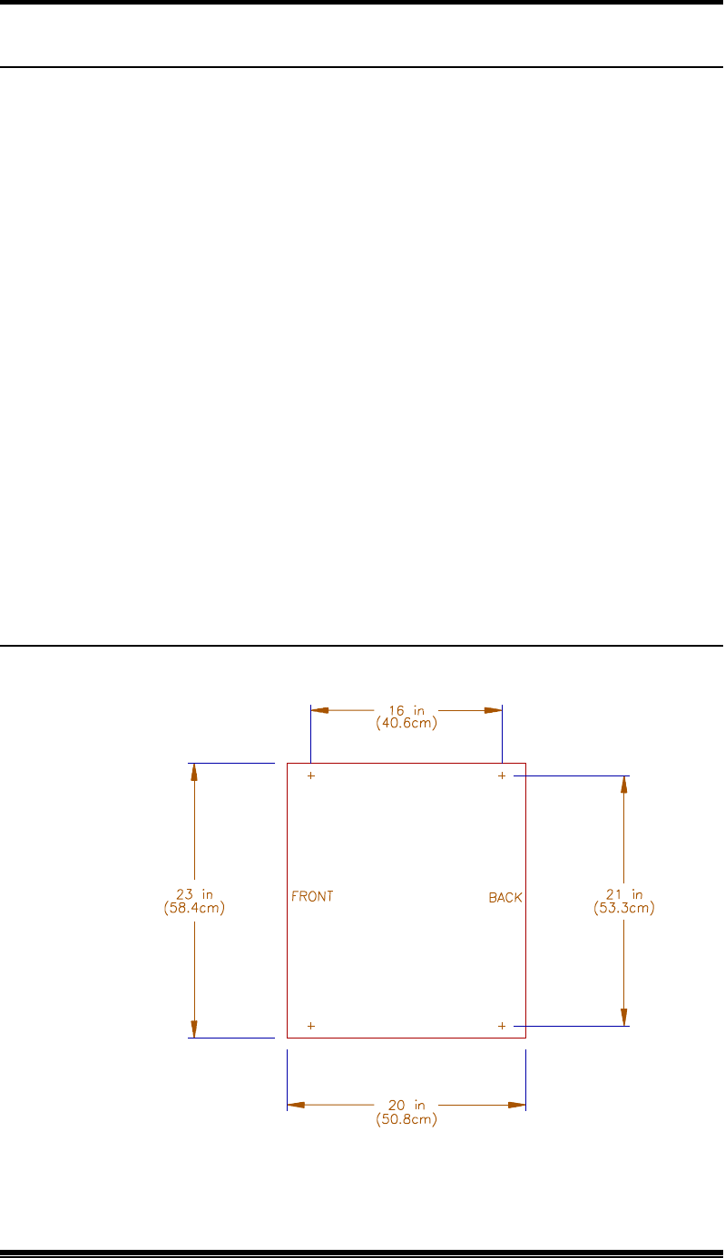
Figure 3-4. Pedestal Footprint
(UPDATE. Also add mounting dimensions of the wall bracket)

3. Installing the Hardware
EAC-2100 Manual: (Draft, 02/01) Page 3-5
3.2.2.1 Mounting the Cabinet on the Pedestal
1. If using expandable anchors, determine the bolt locations (see Figure 3-4)
and drill holes in the pad.
2. Place the pedestal on the pad where it will be installed.
3. Bolt the pedestal to the pad. Be sure to orient the pedestal correctly for
RF cable entry through the ROX blocks.
4. Place the EAC-2100 on the pedestal, assemble and bolt the retaining bars
to clamp it to the pedestal.
3.2.2.2 Mounting the Cabinet on the Wall Bracket
1. Mount the wall bracket to a flat vertical surface. Make sure the bolts and the
structure into which the bolts are fastened are adequate for the weight of the
cabinet. Also, make sure the bracket is mounted high enough to allow access
to the connectors underneath the cabinet.
2. Place the EAC-2100 onto the wall bracket. If not already in place, insert two
CAP screws on upper-rear of the cabinet. Use these two CAP screws to hang
the EAC-2100 in place.
3. Secure the remaining holes in the bracket by placing screws in the appropriate
holes.
3.2.3 Securing the Door
Later, after all installation steps have been completed (including electrical
connections and initial system operation), secure the door as follows:
1. Close the cabinet door.
2. Use the key supplied to lock the upper and lower locks.
3. Place the key in a safe place for later use.
CAUTION: The EAC-2100 weighs 210 pounds (95
kg)! Use appropriate lifting aids to position the unit.
Lifting rings on the cabinet are provided for this
purpose.

3. Installing the Hardware
EAC-2100 Manual: (Draft, 02/01) Page 3-6
3.3 Installing the Antennas
Antennas should already have been mounted, as described in Section 2.4.2, in locations
that meet the following requirements:
• Minimum signal level from any donor cell: -75 dBm or greater at the D1 antenna
connector. (See Section 2.4.2 for multi-hop and multi-donor unit variations.)
• Physical separation: M1 and M2 antennas separated at least 10 feet (3 m)
horizontally or 3 feet (1 m) vertically.
• Isolation between D1 and M1, and between D1 and M2:
− >75 dB
• Modem antenna: Placed so as to minimize interference with the M1, M2, and D1
antennas (minimum 60 dB isolation required). The minimum signal level required
for proper operation is -100 dBm. Alternatively, the data radio may be connected
to the internal donor duplexer sampling port. However, make sure signal level is
enough to make up for the 20 dB coupling loss.
Antenna installation involves connecting the antennas to the EAC-2100, measuring
isolation and signal level, and making needed adjustments.
3.3.1 Connecting the Antennas
Connect the antennas to the EAC-2100. All antenna connectors (type 7/6
DIN) are located on the bottom he cabinet, arranged as shown in Figure 3-5.
Figure 3-5. Antenna Connectors
(NOTE: ADD DRAWING OF BOTTOM HERE)

3. Installing the Hardware
EAC-2100 Manual: (Draft, 02/01) Page 3-7

3. Installing the Hardware
EAC-2100 Manual: (Draft, 02/01) Page 3-8
3.4 Connecting External Alarms/Controls (Optional)
The EAC-2100 includes the following inputs and outputs, which may be used to
monitor or control non-EAC-2100 equipment:
• 4 digital inputs
• 4 open collector digital outputs
• 4 analog inputs
• 1 +5 Vdc/100 mA source for powering external circuitry
These inputs and outputs are located on the DB15 connector on the front of the
controller module. The signals on the pins are controlled and monitored via the local or
remote link. Electrical specifications for the pins are shown in Figure 3-7.
(UPDATE)
Figure 3-6. External Alarm/Control Connector Pin Out
Pin Function Pin Function
1 +5 Vdc/100 mA 14 Ground
2 Ext. Digital Output 4 15 Ground
3 Ext. Digital Output 3 16 Ground
4 Ext. Digital Output 2 17 Ground
5 Ext. Digital Output 1 18 Ground
6 Ext. Digital Input 4 19 Ground
7 Ext. Digital Input 3 20 Ground
8 Ext. Digital Input 2 21 Ground
9 Ext. Digital Input 1 22 Ground
10 Ext. Analog Input 4 23 Ground
11 Ext. Analog Input 3 24 Ground
12 Ext. Analog Input 2 25 Ground
13 Ext. Analog Input 1

3. Installing the Hardware
EAC-2100 Manual: (Draft, 02/01) Page 3-9
3.5 Connecting External Alarms/Control (Optional) (Continued)
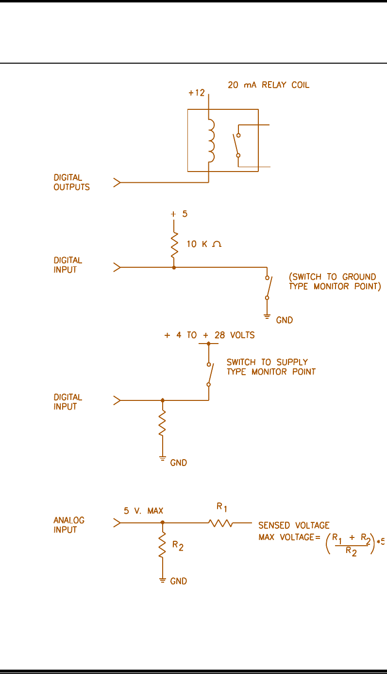
Figure 3-7. Electrical Specifications for Inputs and Outputs
The system designer should have identified any external alarms and controls to be
connected. Make external alarm/control connections as follows:
1. Identify the input/output connection to be used for each external alarm/control that
is to be installed. Figure 3-8 shows a typical wiring diagram for external alarm
input.
2. Make connections using a compatible DB15 male connector (not supplied).
Pins Specifications
Digital Inputs (pins 6,7, 8, 9):
Load: > 100 kΩ
Low: < 2 Vdc
High: > 4 Vdc max. +28 Vdc
Open Collector Outputs (pins 2, 3, 4, 5):
Max. +15 Vdc, 20 mA
Impedance 733 Ω
Analog input (pins
10, 11, 12, 13):
Load: 1 M Ω
Range: 0−5 Vdc, 20 mV resolution
+5 Vdc source (pin 1): +5 Vdc ±5%, 100 mA max.
3. Installing the Hardware
EAC-2100 Manual: (Draft, 02/01) Page 3-10
3.5 Connecting External Alarms/Control (Optional) (Continued)
Figure 3-8. Typical Wiring for External Alarm Input

EAC-2100 Manual: (Draft, 02/01) Page 4-1
4. Setting Up for Initial Operation
4.1 Introduction
Most of the EAC-2100 operating parameters are under software control and can be
changed from either a local terminal or a remote terminal. You will probably have to
change some of these parameters to get the system running. After programming
channels, you will also need to tune the transmitter combiner and adjust power levels.
This section describes procedures for:
• Powering up and powering down the EAC-2100
• Connecting the local terminal
• Becoming familiar with system commands
• Programming initial parameters
• Tuning the transmitter combiner and setting output power
The checklist in Figure 4-1 presents a brief overview of these procedures. For more
detailed descriptions of the procedures, refer to Sections 4.2−4.7. For detailed
descriptions of all parameters, refer to Volume 2, Operating Procedures.
Additional instructions for special EAC-2100 configurations and options are provided
in Sections 7 through 10. If you have problems during setup, refer to Appendix A,
Troubleshooting Guide.

4. Setting Up for Initial Operation
EAC-2100 Manual: (Draft, 02/01) Page 4-2
Figure 4-1. Setup Checklist
Checklist
¨ 1. Local terminal connected: (Sec. 4.2 and 4.4)
¨ a. Terminal powered up and set to 9600 baud, even parity, 7 data bits,
1 stop bit, full duplex, all capitals, send carriage return only, auto
XON/XOFF and soft scroll disabled.
¨ b. EAC-2100 powered up and password entered.
¨ 2. System status (SSS) and alarm (ALA) report checked; no disabled and no
alarms shown. (Sec. 4.6.1)
¨ 3. Site ID entered. (Sec. 4.6.2)
¨ 4. RF Channels programmed:
¨ a. Donor DCCH channel programmed. (Sec. 4.6.3)
¨ b. Boosted DCCH channel programmed. (Sec. 4.6.4)
¨ c. Donor DTC channels entered in DTC channel lists. (Sec. 4.6.5)
¨ d. Boosted DTC channels programmed. (Sec. 4.6.6)
¨ 5. Alarms and thresholds set (if desired). (Sec. 4.6.7)
¨ 6. Modem mobile MIN, mobile power step, and passwords programmed.
(Sec. 4.6.8)
¨ 7. Reverse path power level adjusted. (Sec. 4.7.3)
¨ 8. Clock set. (Sec. 4.7.4)
¨ 9. Call history, call statistics, and alarm report reset to 0: (Sec. 4.7.4)
¨ a. DCH = 0 <CR>
¨ b. DCS = 0 <CR>
¨ c. ALA = 0 <CR>

4. Setting Up for Initial Operation
EAC-2100 Manual: (Draft, 02/01) Page 4-3
4.2 Powering Up the EAC-2100
One circuit breaker turns the AC power on and off to the EAC-2100.
Figure 4-2. EAC-2100 Breaker
Breaker Cabinet Location Controls
Main Bottom center ac service to entire cabinet
4. Setting Up for Initial Operation
EAC-2100 Manual: (Draft, 02/01) Page 4-4
4.3 Connecting a Local Terminal
The EAC-2100 communicates with a conventional ASCII, RS232 terminal. Connect
the terminal as follows.
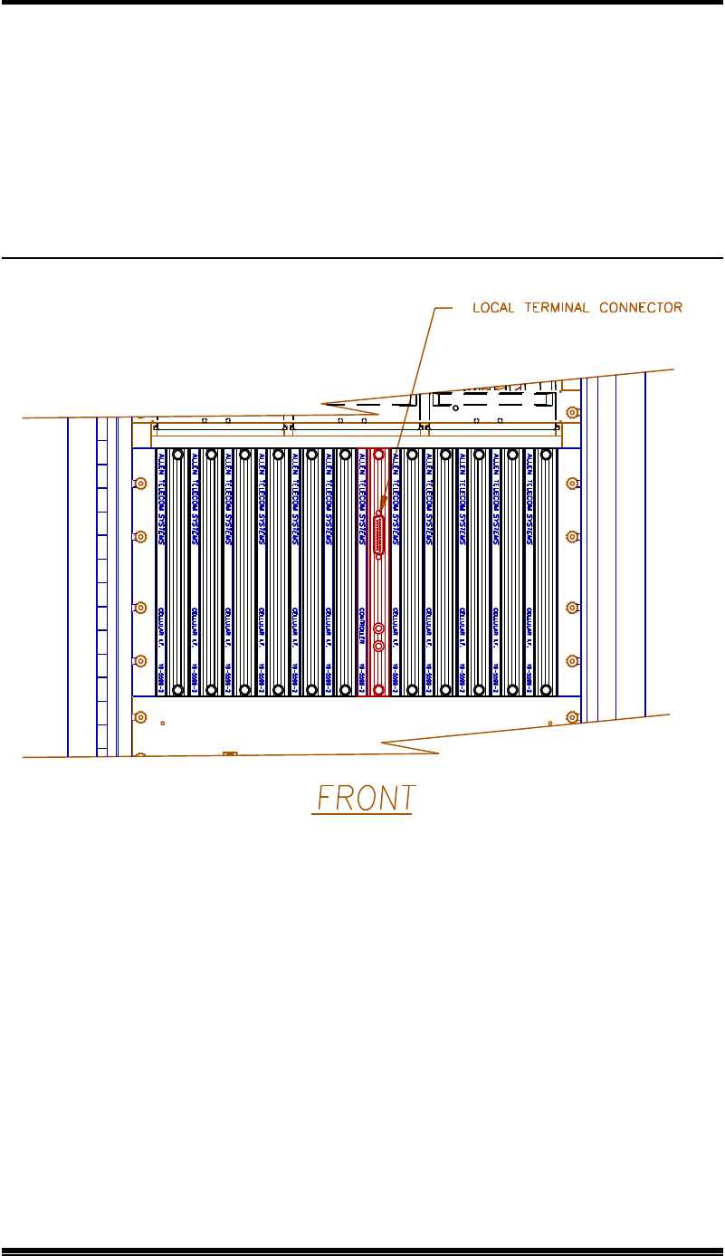
1. Using the cable provided in the tuck pack, connect the terminal to the 9-pin D-sub
connector located on the front of the controller module.
Figure 4-4. Location of Local Terminal Connector

4. Setting Up for Initial Operation
EAC-2100 Manual: (Draft, 02/01) Page 4-5
4.4 Connecting a Local Terminal (Continued)
2. Power up the terminal and set it to the following parameters:
• 9600 baud
• Even parity
• 7 data bits, 1 stop bit
• Full duplex (no local echo)
If possible, also set the terminal to:
• All capitals
• Send carriage return only (no line feed)
• Disable AUTO XON/XOFF and soft scroll
If you are using a terminal emulation program, select TTY or VT100. Be aware
that some terminal emulation programs generate extraneous characters that may
interfere with communicating with the EAC-2100.
3. Power up the EAC-2100. (After about 2 seconds, the terminal should respond
CONSOLE LOCKED.)
4. Enter <CR> (carriage return or enter, depending on the keyboard). (The terminal
should respond with a welcome message and prompt you for a password.)
• If something comes up but is illegible, check the terminal setup.
• If nothing comes up, power down. Recheck the power hookup, the terminal
hookup, and the terminal setup.
5. Enter the password, followed by <CR>. The default password is 1234. (The
terminal should respond with more salutation and the > prompt.) The system is
ready for you to set parameters.

4. Setting Up for Initial Operation
EAC-2100 Manual: (Draft, 02/01) Page 4-6
4.4 Becoming Familiar with System Commands
If you are new to EAC-2100 installation, you should use this section to gain familiarity
with basic rules for entering commands, as well as key commands that will be used in
setting up the system. If you are already familiar with the system, turn to Section 4.6.
4.4.1 Basic Commands
Figure 4-5 lists definitions of symbols and abbreviations that are used in this
section of the manual.
Figure 4-5. Command Definitions
Symbol/
Abbreviation
Definition
> Command entry level. The system uses this prompt character to
indicate it is ready to accept commands.
<CR> Carriage return or enter.
<CTRL> Control. The control key is used in combination with other keys.
For example, <CTRL> Z means to hold down the control key while
pressing the Z key.
ESC Escape. Escape is a single key marked ESC on most keyboards.
Syntax. The system responds to commands that consist of three letters
followed by up to three data fields, as follows:
COM [FIELD 1 -] [FIELD 2 =] [FIELD 3] <CR>
In this syntax:
• COM is the particular three-letter command.
• FIELD 1 consists of up to four hex characters followed by a hyphen (-).
• FIELD 2 consists of up to four hex characters followed by an equals (=)
sign.
• FIELD 3 consists of up to four hex characters.
• Each command ends with a carriage return (<CR>).

4. Setting Up for Initial Operation
EAC-2100 Manual: (Draft, 02/01) Page 4-7
4.5.1 Basic Commands (Continued)
Entering Commands. Very few commands require entry of the data fields.
After the initial command has been entered, the system usually prompts for
data it needs. If a command does not depend on a certain field, any data
entered in that field will be ignored.
When entering commands:
• Spaces may be added to separate the fields, after the first three letters have
been entered.
• Leading zeros may be omitted.
• Use DELETE or BACKSPACE to correct mistakes.
• End the command with <CR>.
Commonly Used Commands. Figure 4-6 lists the commands you are most
likely to use. The most complex command is SET. This command is structured
to enable you to enter parameters easily and accurately. The other commands,
which are much simpler, require little or no subsequent data input. Their action
is complete in a matter of seconds.
F To become familiar with these commands, try each command
(except SET) and observe the system's response.
F NOTE: Use SET and RES with caution! In an operational system,
SET may drop calls if certain parameters are changed. RES will drop
all calls currently being boosted. Otherwise, the system commands do
not interfere with call processing.
Escaping From Continuous Cycles. Some commands enter a mode in which
the program does something continuously. (These commands are indicated by
an asterisk (*) in Figure 4-6.) To get out of this mode and return to the
command entry level, hit <ESC> or type <CTRL> Z.
F NOTE: Entering <ESC> or <CTRL> Z from the command entry
level (>) will cause the characters entered on the line to be erased.
4. Setting Up for Initial Operation
EAC-2100 Manual: (Draft, 02/01) Page 4-8
Figure 4-6. System Commands
Command Meaning Purpose
HEL HELp Gives a list of the primary commands.
SET SETup Invokes a menu-driven entry mode used to inspect or change all EAC-2100
operating parameters. (To exit this command, type <CTRL> X and answer
N <CR>.)
SSS Show
System
Status
Gives a one-page listing of current EAC-2100 parameter settings and conditions
of monitored input parameters
SCS* Show Call
Status Shows current status of each board. Updates listing if status changes (e.g., if a
call is set up or taken down) and gives reason for change.
SSR* Show
Scanned
RSSI
Shows average RSSIs of channels being scanned
RSS* RSSI
Report Gives a continuously updated reading of RSSIs on all RF boards.
ALA ALArm
Report Gives a report of the number of times various alarm conditions have occurred
since last system reset.
DCS Display
Call
Statistics
Displays various call statistics per board (totals since last DCS=0 command).
DCH Display
Call
History
Displays hourly totals of certain call statistics for the last running week.
TIM TIMe Displays/changes current clock time and date.
RES RESet Resets EAC-2100. Parameters in effect when command is issued will be
preserved.
LOC LOCk Forces password entry before accepting subsequent commands
PWR* PoWeR
display Repeatedly lists power readings on all installed PAs.
DVCC* DVCC
report Repeatedly lists the DVCC readings on the boards
REV REVision Displays hardware revisions in the EAC -2100
MIN* Mobile ID
Number Lists the last five access attempts by subscribers
* To exit this command, hit ESC or type <CTRL> Z.

4. Setting Up for Initial Operation
EAC-2100 Manual: (Draft, 02/01) Page 4-9
4.5.1 Basic Commands (Continued)
Ending a Session. A session can be ended in three ways:
• LOC Command: This command should be used if the session involves
only system monitoring or minor parameter changes. It ensures security,
but lets alarms and call statistics continue to accumulate.
• RES Command: This command should be used if extensive parameter
changes have been made during a session. This method:
o Ensures that all parameter changes take effect, since all hardware is
initialized after a reset.
o Ensures security because the password must be reentered to get back
to the command level.
o Initializes all alarm condition counters to 0.
• Inactivity Timeout: An inactivity timer is included in the program with a
default inactivity timeout setting of 5 minutes. If a keyboard entry is not
detected within the designated period, the system terminates any currently
running command (e.g., SET) and simulates the action of LOC. This
avoids leaving the EAC-2100 in an insecure state if the remote link is lost
before the session is properly ended.
F NOTE: If a remote terminal is linked by modem to the EAC-2100,
LOC, RES or timeout will terminate the link.

4. Setting Up for Initial Operation
EAC-2100 Manual: (Draft, 02/01) Page 4-10
4.4.2 Using the SET Menus
Configuring the EAC-2100 to fill in a coverage area in a specific cell ular
system is easy, using either the local terminal or a remote terminal. From the
command entry level (>), the SET command invokes the setup utility which
displays a progression of menus. The menus provide a guided path to each
EAC-2100 parameter. Figure 4-7 illustrates the paths to follow through the
SET menus to reach each available parameter. For descriptions of all SET
menus and commands, see Volume 2, Operating Procedures.
Moving Forward. Each command brings up a menu of items from which to
choose, with a character in front of each item. To select an item, type the
character and <CR>. The next menu (or the parameter to be changed) will be
displayed.
Moving Backward. To move backward along a path, type X <CR>, or just
<CR>. (Both entries correspond to the "Done with this menu" selection.) The
previous menu will be displayed. Continue in this manner until you have the
SET Main Menu.
Exiting. To exit SET, type <CTRL> X at any menu level. Or, type X <CR>
while at the Main Menu level.
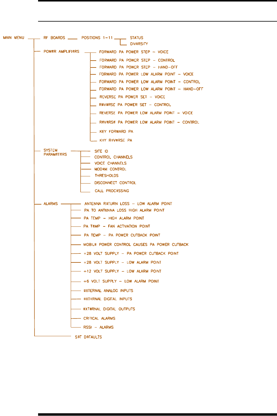
4. Setting Up for Initial Operation
EAC-2100 Manual: (Draft, 02/01) Page 4-11
Figure 4-7. SET Command Menu Map

4. Setting Up for Initial Operation
EAC-2100 Manual: (Draft, 02/01) Page 4-12
4.5 Setting Initial Parameters
Before you can operate the EAC-2100, you must check system status and program the
following:
• Site identification
• Donor DCCH channel
• Boosted DCCH channel
• Directed retry channels
• Donor DTC channels
• Boosted DTC channels
You should already have the list of selected channels, as described in Section 2.4. You
may also program alarms and thresholds, modem mobile MIN, mobile power step, and
passwords at this time.
4.5.1 Checking System Status
Check the system status, as follows, to be sure parameters were returned to
default status after factory testing.
1. At the > prompt, type SSS <CR>. (A report will be displayed giving the
current state of various parameters for each RF board.)
2. At the > prompt, type ALA <CR>. (A report will be displayed giving the
number of times various alarm conditions have occurred since the last
system reset.)
No alarms should be listed. If there are any OUT OF SERVICE or memory
alarms, refer to Appendix A, Troubleshooting Guide.
If the EAC-2100 is to be used in a Multi-hop application, additional parameters
must also be set. See Section 7 for procedures.

4. Setting Up for Initial Operation
EAC-2100 Manual: (Draft, 02/01) Page 4-13
4.5.2 Entering the Site ID
1. At the > prompt, type SET <CR> to display the SET Main Menu.
2. Type C <CR> to display the System Parameters Menu.
3. Type A <CR> to display the Site ID Menu (shown below with default
values).
4. Type A <CR> to access the Site Identification parameter.
5. Enter a name (up to 20 characters) that uniquely identifies the site.
6. Type X <CR> to back out of the Site ID Menu.
Main Menu A RF Boards
B Power Amplifiers
C System Parameters
D Alarms
E Set Defaults
System Parameters Menu
A Site ID........................... Identification Multi-Hop
B DCCH Channels ...........Donor Boosted State
C DTC Channels ..............Donor Donor DVCC Boosted
D Modem Control.............Passwords Console Time-out Auto-Dial Control
Dial-up Phone Modem Mobile
E Thresholds.....................Hand-In Hand-Back Multi-Donor
Mobile Power RSSI Averaging Hand-In Delay
F Disconnect Control .......Donor RSSI DVCC Fade Time-out
Hand-Back Delay Hand-Back Attempts
G Call Processing ..............RSSI > Thresh Hand-Back / Grab-Back
Site ID Menu
Default Values
A Site Identification ................................ ................................ ......Not Assigned
B Multi-Hop Feature..........................................................................DISABLED

4. Setting Up for Initial Operation
EAC-2100 Manual: (Draft, 02/01) Page 4-14
4.5.3 Setting the Donor DCCH Channel
1. From the System Parameters Menu, type B <CR> to display the
Control Channels Menu.
F NOTE: This menu represents all selections available on the Control
Channels Menu. Not all selections appear at all times. Following are
selections that are only available when used in conjunction with other
parameters:
• E - Directed Retry Channels: Appears only if selection D (DCCH
Channel State During "All Channels Busy") is set to Directed Retry.
4.5.3 Setting the Donor ControDCCH Channel (Continued)
2. Type A <CR> to access the Donor DCCH Channel parameter.
3. Enter the channel number (see Section 2.4), then <CR>.
4. To return to the Control Channels Menu, type X <CR>.
4.5.4 Setting the Boosted DCCH Channel
1. From the Control Channels Menu, type B <CR> to access the Boosted
DCCH Channel parameter. This parameter establishes the boosted DCCH
channel, to which combiner port 1 is tuned.
2. Enter the channel number (see Section 2.4), then <CR>.
4.5.5 Setting the Directed Retry Channels
1. From the Control Channels Menu, type E <CR> to access the Directed
Retry Channels parameter.
2. Enter the DCCH channel numbers of all nearby cells, including the donor.
The mobile will be directed to attempt calls on these channels when the
EAC-2100 is busy.
3. To return to the System Parameters Menu, type X <CR> twice.
DCCH Channels Menu
A Donor DCCH Channel ................................ ................................ ..................... 335
B Boosted DCCH Channel ..................................................................................... 340
C RF Board To Use For DCCH Channel ....................................................................1
D DCCH Channel State During "All Channels Busy" ...............DIRECTED RETRY
E Directed Retry Channels ....................................................................................LIST

4. Setting Up for Initial Operation
EAC-2100 Manual: (Draft, 02/01) Page 4-15
4.5.6 Setting the Donor DTC Channels
1. From the System Parameters Menu, type C <CR> to display the DTC
Channels Menu.
2. Type A, B, or C, followed by <CR>, to access the Donor DTC Channels
Menu for the corresponding DVCC.
DTC Channels Menu
Default Values
A DTC Channels DVCC List A ................................ ................................ .......... List
B DTC Channels DVCC List B................................ ................................ ........... List
C DTC Channels DVCC List C ................................ ................................ .......... List
2 Boosted DTC Channel Position 2........................................................................361
3 Boosted DTC Channel Position 3........................................................................382
4 Boosted DTC Channel Position 4........................................................................403

4. Setting Up for Initial Operation
EAC-2100 Manual: (Draft, 02/01) Page 4-16
4.6.6 Setting the Donor DTC Channels (Continued)
3. Enter channels in the list, as described below. A given channel may be
entered in only one list. The system will support a maximum of 105 total
channels in all four lists (A, B, C, and M).
A. To add a channel, type A [channel number] <CR>.
B. To add multiple channels, after the A enter multiple channel
numbers separated by commas or spaces. If you enter a plus (+) sign
before a single channel entry, 15 channels will be added, spaced 21
channels apart, starting with the channel entered. You can then delete
extra channels as necessary.
C. To remove a channel from the list, type R [channel number] <CR>.
D. To remove multiple channels, after the R enter multiple channel
numbers separated by commas or spaces. To remove the entire list,
type ALL.
4. To return to the DTC Channels Menu, type X <CR>.

4. Setting Up for Initial Operation
EAC-2100 Manual: (Draft, 02/01) Page 4-17
4.5.7 Setting the Boosted DTC Channels
The DTC Channels menu gives you access to boosted DTC channels 2−4.
Boosted channel 1 is normally used to boost the DCHH channel. Program
channels 2−4 as follows.
1. Type the channel number (2 to 4), followed by <CR> to access the desired
corresponding Boosted DTC Channel parameter.
2. Enter the channel number, followed by <CR>.
3. To return to the DTC Channels Menu, type X <CR>.
4. Repeat steps 1−3 for each boosted DTC channel.
4.5.8 Programming Alarms and Thresholds
1. From the SET Main Menu, type D <CR> to display the Alarms Menu
(shown below with default values).
Alarms Menu
Default Values
A
M1 Antenna return loss - Low Alarm Point .........................................6 dB
B M2 Antenna return loss - Low Alarm Point .........................................9 dB
C PA Temp - High Alarm Point ........................................................90 Deg C
D PA Temp - Fan Activation Point....................................................60 Deg C
E PA Temp - PA Power Cutback Point.............................................90 Deg C
F Mobile Power Control causes PA Power Cutback....................DISABLED
G +28 Volt Supply - PA Power Cutback Point................................23.0 Volts
H +28 Volt Supply - Low Alarm Point.............................................23.0 Volts
I +12 Volt Supply - Low Alarm Point.............................................10.0 Volts
J +6 Volt Supply - Low Alarm Point.................................................5.4 Volts
K External Analog Inputs..............................................................Alarm Points
L External Digital Inputs ..............................................................Alarm States
M External Digital Outputs....................................................................... States
N
Critical Alarms.........................................................ALARMS REPORTED
O RSSI - Alarms................................................................... ALARM POINTS

4. Setting Up for Initial Operation
EAC-2100 Manual: (Draft, 02/01) Page 4-18
4.6.8 Programming Alarms and Thresholds (Continued)
2. Type D <CR> to set the fan activation point (the internal temperature that
causes the cabinet heat exchanger to be turned on).
The 60oC default setting is adequate for most installations. Lower the
threshold to 50oC if the DCCH channel transmitter output is increased to
its maximum (45W) output level.
3. Type H <CR> to access the +28 Volt Supply - Low Alarm Point
parameter.
Loss of ac power will cause the EAC-2100 to run on power from the
battery plant (if installed). The battery voltage will drop to the low alarm
point after a period of time, causing an alarm.
The default value (23.0 V) will be adequate for most installations. If an
external battery plant is used, the low alarm point may be adjusted upward
(e.g., to 25−26 V) if desired to provide an immediate alarm in the event of
the loss of ac power.

4. Setting Up for Initial Operation
EAC-2100 Manual: (Draft, 02/01) Page 4-19
4.6.8 Programming Alarms and Thresholds (Continued)
4. If external analog inputs are connected to the EAC-2100 external
alarm/controls ports, type K <CR> to access the External Analog Inputs
menu.
Choose the number of the input(s) connected and program the alarm point.
You may specify DISABLED or ABOVE/BELOW a threshold, which may be
between 0 and 5 Volts.
F NOTE: If PA 7−11 Cage is not included in the unit, then the
hardware for those inputs is not installed and the alarms should be left
as DISABLED.
External Analog Inputs Menu
PA 1−6 Cage:
1 Ext. Analog Input 1 Alarm State DISABLED; Input Currently 0.0 Volts
2 Ext. Analog Input 2 Alarm State DISABLED; Input Currently 0.0 Volts
3 Ext. Analog Input 3 Alarm State DISABLED; Input Currently 0.0 Volts
4 Ext. Analog Input 4 Alarm State DISABLED; Input Currently 0.0 Volts
PA 7−11 Cage:
5 Ext. Analog Input 1 Alarm State DISABLED; Input Currently 0.0 Volts
6 Ext. Analog Input 2 Alarm State DISABLED; Input Currently 0.0 Volts
7 Ext. Analog Input 3 Alarm State DISABLED; Input Currently 0.0 Volts
8 Ext. Analog Input 4 Alarm State DISABLED; Input Currently 0.0 Volts

4. Setting Up for Initial Operation
EAC-2100 Manual: (Draft, 02/01) Page 4-20
4.6.8 Programming Alarms and Thresholds (Continued)
5. If external digital inputs are connected to the EAC-2100 external
alarm/controls ports, type L <CR> to access the External Digital Inputs
menu.
Choose the number of the input(s) connected and program the alarm state.
You may specify DISABLED, HIGH or LOW.
6. If external digital outputs are connected to the EAC-2100 external
alarm/controls ports, type M <CR> to access the External Digital
Outputs menu.
External Digital Inputs Menu
PA 1−6 Cage:
1 Ext. Digital Input 1 Alarm State DISABLED; Input Currently Low
2 Ext. Digital Input 2 Alarm State DISABLED; Input Currently Low
3 Ext. Digital Input 3 Alarm State DISABLED; Input Currently Low
4 Ext. Digital Input 4 Alarm State DISABLED; Input Currently Low
PA 7−11 Cage:
5 Ext. Digital Input 1 Alarm State DISABLED; Input Currently Low
6 Ext. Digital Input 2 Alarm State DISABLED; Input Currently Low
7 Ext. Digital Input 3 Alarm State DISABLED; Input Currently Low
8 Ext. Digital Input 4 Alarm State DISABLED; Input Currently Low
External Digital Outputs Menu
PA 1−6 Cage:
1 Ext. Digital Output 1 State....................................................................... LOW
2 Ext. Digital Output 2 State....................................................................... LOW
3 Ext. Digital Output 3 State....................................................................... LOW
4 Ext. Digital Output 4 State....................................................................... LOW
PA 7−11 Cage:
5 Ext. Digital Output 1 State....................................................................... LOW
6 Ext. Digital Output 2 State....................................................................... LOW
7 Ext. Digital Output 3 State....................................................................... LOW
8 Ext. Digital Output 4 State....................................................................... LOW

4. Setting Up for Initial Operation
EAC-2100 Manual: (Draft, 02/01) Page 4-21
4.6.8 Programming Alarms and Thresholds (Continued)
Choose the number of the output(s) connected and program the desired state.
You may specify:
• Low
• Low if critical alarm exists
• High
• High if critical alarm exists
The "low/high if critical alarm exists" options are provided to allow for
connection to external alarm signaling equipment.
7. Type N <CR> to review the Critical Alarms Menu, shown here with
default values.
F NOTE: This illustration represents the complete Critical Alarms
Menu. In actual application, only half of the Critical Alarms
Menu can be viewed at a time due to minimal screen space. To
access additional Critical Alarms Menu selections, type Z <CR>.
Critical Alarms Menu
Default Values
A
Board Out-of-Service Alarm ........................................................... CRITICAL
B Board ROM Alarm.......................................................................... CRITICAL
C Board Calibration Memory Alarm .................................................. CRITICAL
D Serial Data Link Alarm.................................................................... CRITICAL
E Personality Mismatch Alarm ........................................................... CRITICAL
F Synthesizer Unlocked Alarm........................................................... CRITICAL
G RVS PA Pwr Low Alarm................................................................ CRITICAL
H RSSI Alarm....................................................................................LOG ONLY
I PA Out-of-Service Alarm ................................................................ CRITICAL
J PA Temp - High Alarm................................................................. LOG ONLY
K PA Power - Low Alarm................................................................... CRITICAL
L PA to Antenna Loss High Alarm.................................................... CRITICAL
N
ROM Alarm..................................................................................... CRITICAL
O RAM Alarm..................................................................................... CRITICAL
P NOVRAM Alarm............................................................................ CRITICAL
R Power Supply Voltages - Low Alarm ............................................. CRITICAL
S External Analog Input Alarm........................................................LOG ONLY
T External Digital Input - Alarms .....................................................LOG ONLY
Z Display More Critical Alarms

4. Setting Up for Initial Operation
EAC-2100 Manual: (Draft, 02/01) Page 4-22
4.6.8 Programming Alarms and Thresholds (Continued)
Critical alarms will cause the EAC-2100 to automatically dial an alarm
telephone number when the Auto-Dial feature is enabled. Log only
alarms will be counted and displayed in the ALA screen, but will not
cause the EAC-2100 to dial its programmed alarm number.
The default values shown below will be adequate for most installations.
To change an alarm, type the letter of that alarm and <CR>.
To alternate between the two Critical Alarms Menu displays, type Z
<CR>.
8. Type O <CR> at the Alarms Menu to review the RSSI Alarms Menu.
B Donor DCCH Channel RSSI - Low Alarm Point is the most critical
of these alarm thresholds. This threshold should be set lower (within a
range of -85 to -95 dBm), to ensure continued operation, under the
following circumstances:
• If the booster is being operated at a minimum (-75 dBm) donor signal
level and some fading exists on the donor-to-booster path.
A and C, Donor DCCH/DTC Channel RSSI - High Alarm Points, may
be set at a level 10−15 dB higher than the normal signal levels being
received from the donor, if desired. This will allow the EAC-2100 to log
alarms in the event of IF board failures with their RSSI measuring circuits.
RSSI Alarm Points Menu Default Values
A
Donor DCCH Channel RSSI - High Alarm Point................................. NONE
B Donor DCCH Channel RSSI - Low Alarm Point...............................-80 dBm
C Donor DTC Channel RSSI - High Alarm Point.....................................NONE

4. Setting Up for Initial Operation
EAC-2100 Manual: (Draft, 02/01) Page 4-23
WARNING!! Use the minimum power step
allowable to minimize the possibility of overloading
the EAC-2100's reverse input preamplifier.
4.5.9 Programming the Modem Mobile MIN, Mobile Power Step, and
Passwords
The assigned mobile identification number (MIN) of the mobile and the
desired mobile power step should be loaded into the booster. This allows the
booster to trap calls to and from the remote link to force operation on the
donor DTC channels. By doing so, the remote link does not tie up one of the
boosted DTC channels. Passwords may also be programmed now.
1. From the System Parameters Menu, type D to display the Modem Control
Menu, shown here with default values.
2. Type K <CR> to access the Modem Mobile MIN parameter.
3. Enter the 10-digit MIN, followed by <CR>.
4. Type L <CR> to access the Modem Mobile Power Step.
5. Enter the desired power level step (7 = minimum, 0 = maximum). Enter
<CR> to record the desired power step.
6. If desired, use menu entries A and B to enter the passwords.
(They may be left at the defaults for now if desired.)
Modem Control Menu Default Values
A
Master Password.................................................................................................1234
B Restricted Password............................................................................................5678
C Console Time-out.................................................................................30 (x 10 Sec)
D Auto-dial Enable ....................................................................................DISARMED
E Dial-up Phone Number 1 ....................................................................12163498684
F Dial-up Phone Number 2 ............................................................................... NONE
G Auto-dial Trials Max...............................................................................................10
H Delay Between Auto-dial Retries ............................................................6 (x 10 sec)
I Max Auto-dial Trial Period......................................................................9 (x 10 sec)
J Modem Setup...................................................................................PARAMETERS
K Modem Mobile MIN .............................................................................1234567890
L Modem Mobile Power Step......................................................................................7

4. Setting Up for Initial Operation
EAC-2100 Manual: (Draft, 02/01) Page 4-24
4.6 Setting Output Power
4.6.1 Setting Power Levels for Forward PAs 1−4
1. With the system power OFF, connect power measuring equipment to the
M1 antenna port for channels 1 and 2, and to the M2 antenna port for
channels 3 and 4. Turn the power back on. Output power may be
monitored using a through-line wattmeter (or a wattmeter with a built-in
load) to monitor output power.
2. From the SET Main Menu, type B <CR> to display the Power Amplifiers
Menu.
3. Type K <CR> to key a forward PA.
4. Type 1 <CR> to key PA 1 and display the forward power output as
measured at the sensor.
Power Amplifiers Menu
Default Values
A
Forward PA Power Step - DTC........................................................................0
B Forward PA Power Step - DCCH ....................................................................0
C Forward PA Power Step - Hand-off .................................................................0
D Forward PA Power Low Alarm Point - DTC..................................... +40 dBm
E Forward PA Power Low Alarm Point - DCCH .................................+40 dBm
F Forward PA Power Low Alarm Point - Hand-off ..............................+40 dBm
G Reverse PA Power Set - DTC ............................................................+20 dBm
H Reverse PA Power Set - DCCH.........................................................+20 dBm
I Reverse PA Power Low Alarm Point - DTC .....................................+15 dBm
J Reverse PA Power Low Alarm Point - DCCH..................................+15 dBm
K Key Forward PA .................................. POWER ADJ/COMBINER TUNING
L Key Reverse PA...................................................POWER MEASUREMENT

4. Setting Up for Initial Operation
EAC-2100 Manual: (Draft, 02/01) Page 4-25
4.7.1 Adjusting Power Levels for PAs 1−4 (Continued)
5. Set the desired power level in dBm
• If using a wattmeter, record the actual power reading (note, there may
be small differences between the entered power level and the actual
measured power level due to tolerances of the internal power reading
circuitry and the external power meter).
• The power reading at the M1 connector (for channels 1 & 2) or the
M2 connector (for channels 3 & 4) should be +40.8 ± 1 dBm (12.5
watts nominal).

4. Setting Up for Initial Operation
EAC-2100 Manual: (Draft, 02/01) Page 4-26
4.6.2 Setting Reverse Path Output Power (If Necessary)
The output power in the reverse direction (from booster to donor cell) is +20
dBm per channel. It is set at a much lower level than in the forward direction to
prevent reuse interference with other cells that may be in the system. If the
minimum received signal requirements are met for the forward direction, then
by reciprocity +20 dBm per channel in the reverse direction is sufficient.
F NOTE: Adjustment of the reverse power level is seldom needed.
However, in certain installations the output level may need to be
reduced.
The +20 dBm output level can be reduced with the following procedure:
1. From the SET Main Menu, type B <CR> to display the Power Amplifiers
Menu.
2. Use selections I and J , the reverse PA power for DTC and DCCH
channels.
3. Enter the desired level from +5 to +20 dBm.
Another way to remedy this situation is to install pads in increments of 10 dB
between the donor antenna and the donor duplexer ANT connector. This
method has the added advantage of increasing effective antenna isolation.
4.6.3 Setting PA Power Low Alarm Points
Note that the Power Amplifiers Menu also includes the low power alarm
points. The default values are appropriate for PAs set to the factory power
levels.
If the power outs have been adjusted lower than this, reduce the alarm points
as well. Normally, the alarm point should be set 5 dB lower than the power
reported on the terminal while keyed.

4. Setting Up for Initial Operation
EAC-2100 Manual: (Draft, 02/01) Page 4-27
4.6.4 Setting Time and Report Values
The EAC-2100 keeps various statistics of calls handled by the booster and
alarms that have been logged:
• Running totals of the number and duration of calls handled per board can
be displayed using the DCS command.
• Incremental totals of certain call statistics can be displayed using the DCH
command.
• Alarms logged since the last system reset can be displayed using the ALA
command.
The EAC-2100 clock is used in updating these statistics. To set the clock and
reset the report values to 0, complete the following steps:
1. At the > prompt, type TIM to access the clock. Enter the current date and
time.
2. Type DCH=0 to reset the Display Call History parameter.
3. Type DCS=0 to reset the Display Call Statistics parameter.
4. Type ALA=0 to reset the Alarm Report parameter.

EAC-2100 Manual: (Draft, 02/01) Page 5-1
5. Installing the Remote Link
5.1 Introduction
The EAC-2100 normally will be equipped with an Ericsson T18D handset for remote
link access. Use of the T18D for remote access will require that the local TIA-136
system have digital data service to the handset enabled. This is in addition to the
normally available data originate feature available in TIA -136 systems.
An alternative interface may be provided via the PCMCIA interface on the front of the
controller card. In this case, a PCMCIA card that has wireless radio capability (either
analog or digital) may be plugged into this slot. The PCMCIA front connector will
then be used to interface with a compatible handset or mobile.
The PCMCIA slot may also be used with a wire-line type of PCMCIA modem for
connection to a telephone line.
When data-terminate capability is enabled in the cellular switch, the T18D handset in
the EAC-2100 may be dialed using a remote terminal and compatible modem.
Once the remote link is established, the interface with the system is exactly like that on
the local link, but possibly at a different baud rate. If both links are up, characters typed
on either terminal are echoed to both, along with the resulting EAC-2100 output. This
makes it possible for an experienced operator to exercise the system remotely while
someone watches locally, or for the two to exercise the system together.
Procedures. Establishing the remote link involves:
• Setting up service to the handset
• Programming the handset
• Checking out the handset
• Testing the remote link

5. Installing the Remote Link
EAC-2100 Manual: (Draft, 02/01) Page 5-2
5.1 Introduction (Continued)
The checklist in Figure 5-1 presents a brief overview of these procedures. For more
detailed descriptions of the procedures, refer to Sections 5.2−5.5.
Figure 5-1. Remote Link Installation Checklist
5.2 Setting Up Service
1. Set up service to the Ericsson T18D handset by contacting the local cellular service
supplier. Provide them with the mobile serial number.
2. Obtain from the service supplier the values for the parameters that will be
programmed into the handset.
3. Be sure the MIN of the cellular mobile has been loaded into the booster (see
Section 4.6.9).
Checklist
¨ 1. Service set up with local supplier. (Sec. 5.2)
¨ 2. T18D handset programmed: (Sec. 5.3)
¨ 3. Handset checked out for proper operation: (Sec. 5.4)
¨ a. Powering up.
¨ b. Call originating.
¨ c. Answering.
¨ 4. Remote link tested:
¨ a. EAC-2100 Answering tested. (Sec. 5.5.1)
¨ b. EAC-2100 Originating tested. (Sec. 5.5.2)

5. Installing the Remote Link
EAC-2100 Manual: (Draft, 02/01) Page 5-3
5.3 Programming the Handset
The handset is programmed via its keyboard.
F NOTE: Procedure for programming the T18D to be provided later.
Once programming and initial testing is complete, the handset should have its interface
cable and RF cable connected, and then placed in the bottom of the cabinet. It should
be secured via the clamp provided.
5.4 Checking Out the Handset
After the handset has been set up and programmed, check it for proper operation by
completing the following steps.
1. With the handset connected, power up the EAC-2100. After a short while, it should
indicate that it has service.
• If the handset does not come into service, check the antenna, the antenna
connection and the mobile programming.
2. Make sure the handset can originate and answer calls in the conventional fashion.
The handset can be used to communicate with a partner while trying to optimize
the booster performance.
3. Dial the handset using another cellular phone. The handset should ring a few times,
and then answer.

5. Installing the Remote Link
EAC-2100 Manual: (Draft, 02/01) Page 5-4
5.5 Testing the Remote Link
After the remote link has been installed and programmed, you should test its operation.
The EAC-2100 should be able to answer calls placed from the remote link. It should
also be able (if so programmed) to place calls to a predetermined number when certain
alarm conditions exist.
5.5.1 EAC-2100 Answering
The EAC-2100 constantly monitors and answers incoming calls even if it is
being exercised via the local link. To test the booster's ability to answer calls
from the remote link, complete the following steps.
1. Ensure that the remote link has been installed as required:
• Conventional ASCII terminal
• Terminal and modem set to:
o Appropriate baud rate for the modem (normally 9600 baud)
o 7 data bits, even parity, 1 stop bit
o Full duplex (no local echo)
2. Dial the phone number of the handset in the EAC-2100. (After about one
ring, the EAC-2100 will answer and try to set up communication.)
• If the modems fail to connect, the modems will terminate the call after
a set period of time.
• If the modems are successful in establishing a link, the remote modem
will indicate CONNECT.
3. Type <CR>. (The familiar EAC-2100 response should appear.)
If there are illegible characters, check the modem/terminal parameter
setup.

5. Installing the Remote Link
EAC-2100 Manual: (Draft, 02/01) Page 5-5
5.5.2 EAC-2100 Originating
The EAC-2100 constantly monitors and logs several alarm conditions. These
conditions can be viewed using the ALA command. They are described in
Volume 2, Operating Procedures.
Each type of alarm can be defined as "critical" or "log only" using the SET
command. If an alarm defined as critical occurs more than a predetermined
number of times, a critical alarm is said to exist. The system indicates any
critical alarms at the beginning of each communication session.
The system can also be set up to call a predetermined number if a critical
alarm exists. (The default setup is NOT to place a call when a critical alarm
exists.) If the system has been programmed to automatically report alarms, it
will attempt to do so only if all of the following conditions exist:
• A critical alarm exists.
• The console is locked.
• The handset is connected and in service.
• The system has not successfully reported an alarm since the "Auto-Dial
Enable" parameter was set to ARMED.
• The system has not unsuccessfully tried to report an alarm more than the
designated number of times (the Auto-Dial Trials Max parameter) since
the Auto-Dial Enable parameter was set to ARMED.

5. Installing the Remote Link
EAC-2100 Manual: (Draft, 02/01) Page 5-6
5.5.2 EAC-2100 Originating (Continued)
Successful Call Sequence. When an auto-dial call is made, the following
sequence occurs:
1. As the call is auto-dialed, the local console displays DIALING REMOTE
LINK. (<CR> from the local link at this point will abort the attempt.)
2. After the number is dialed, the EAC-2100 waits up to 90 seconds for a
remote modem to answer and establish a connection.
3. Five seconds after connect, the EAC-2100 automatically lists the alarm
report. The report is echoed locally.
4. If the connection stays up for the duration of the report listing, the attempt
is considered successful. The EAC-2100 disarms itself after a successful
call to prevent duplicate reports.
5. After the report, the system waits up to 60 seconds for a <CR>. If a
<CR> is received, a normal interactive session begins. Otherwise, the
EAC-2100 ends the call.
6. If a second dial-up phone number is programmed, the sequence will be
repeated using the second number.
Unsuccessful Call Attempts. The system will abort the call and consider the
attempt a failure if either of the following occurs:
• The modems do not connect within a set period of time (the programmed
"Max Auto-Dial Trial Period" parameter, default 90 seconds).
• The modems connect, but lose the connection before the entire report is
listed.
After a failed attempt, the system will display the message ORIGINATION
ATTEMPT FAILED on the local console. It will then wait a specified period of
time (the programmed "Delay Between Auto-Dial Retries" parameter). If all
the conditions for making the call are still in effect, another attempt will be
made.
One way to test the call origination feature is to artificially create an alarm by
setting the +28 Volt Supply - Low Alarm Point to +35 Volts.

EAC-2100 Manual: (Draft, 02/01) Page 6-1
6. Optimizing Performance
6.1 Introduction
After the EAC-2100 has been installed, the system must be checked out to determine if
adjustments to the hand-in and handback thresholds are needed to ensure optimum
performance.
6.2 Handoff from EAC back to donor – “Handback”
When the subscriber is operating on the EAC 2100 DTC, the donor cell is not aware
that the EAC is handling the call. Should the subscriber move towards the donor, the
EAC itself must initiate the handoff. To facilitate this, the subscriber unit is directed to
make and report MAHO measurements on the donor and all the neighbors of the donor.
The EAC looks at two of the RSSI measurements. The MAHO RSSI report for the
donor DCCH would be the RSSI at the mobile from the donor, if the donor were to
handle the call. The RSSI report for “current” channel is the RSSI at the mobile from
the EAC. The EAC will send a handoff message to the portable, directing it back to the
donor DTC (same slot) if one of the two following criteria are met:
a) Donor RSSI reported by the mobile’s MAHO list is better than the EAC
parameter:
“HAND-BACK THRESHOLD – DTC –LOAD SHED LEVEL”
OR
b) Donor RSSI is better than the EAC RSSI reported by the mobile’s MAHO list
by at least the level set for the EAC parameter:
“HANDBACK THRESHOLD – DTC – MINIMUM IMPROVEMENT”.
So, with DTC, the presence of the MAHO information allows the EAC to hand a call
back to the donor if the donor can handle it, even if the call would be stronger on the
EAC (option a above, load shed level). This allows the EAC to reserve its DTC
resources for calls that only it can serve.
Note that either parameter may be set to disabled to disable handback due to that
criteria, and if both are set to “disabled” handback by the EAC to the donor will be
disabled altogether.

5. Installing the Remote Link
EAC-2100 Manual: (Draft, 02/01) Page 6-2
6.3 Handoff from EAC to a cell adjacent to the donor
Handoff from the EAC-2100 to adjacent cells happens almost automatically because of
the fundamental role of the subscriber unit in the TDMA handoff process.
When a call is operating on the EAC-2100, the MAHO reports from the subscriber are
repeated back to the donor. The donor compares the RSSI reports from the adjacent
cells to the “current RSSI”. If the RSSI from the adjacent cell is better by a sufficient
amount, the donor will do the handoff. The only role the EAC-2100 has is to accurately
repeat the MAHO information back to the donor, and it does this. The donor does not
realize that the “current RSSI” that the mobile is reporting is really coming from the
EAC-2100, however, that does not matter. It is still proper for the call to be handed off
to one of the cells adjacent to the donor if that cell can handle the call better than the
EAC-2100.
No adjustments or parameters in the EAC-2100 will affect or control this handoff case.
The EAC-2100 does monitor for handoff messages sent by the donor, and these
occurrences are reported in the “SCS” screen and in the “DCS” call statistics.
6.4 Handoff from donor to EAC – “Hand-in”
Calls that are operating on a donor DTC channel are handed in to the EAC by the
following process:
- The EAC uses an available TDMA board to keep track of the average RSSI
from mobiles on donor DTC channels.
- As the subscriber gets closer to the EAC coverage area, the average RSSI will
exceed a preset threshold. The EAC will then periodically decode the data
coming from the subscriber unit and extract the DVCC and MAHO
information.
- If the DVCC is correct, the EAC will attempt to hand-in the mobile when
BOTH of the following conditions are met:
The RSSI at the subscriber from the donor must be weaker than the level set in the
EAC parameter:
“HANDIN THRESHOLD – DTC – LOAD SHED LEVEL”
AND
The RSSI at the portable from the EAC must be better than the RSSI at the
subscriber unit from the donor by:
“HANDIN THRESHOLD – DTC – MINIMUM IMPROVEMENT”.

5. Installing the Remote Link
EAC-2100 Manual: (Draft, 02/01) Page 6-3
Note that the RSSI that the portable subscriber would experience from the EAC is
computed from the average RSSI at the EAC from the portable and the PA power
settings.
Once the signal conditions are met, the EAC will attempt a hand-in by using an
available RF Module to send a handoff message to the subscriber. If the signal level at
the subscriber is at least 3 dB better from the EAC, it will take the handoff message and
move to the EAC-2100 DTC channel, and the EAC-2100 will handle the call.
If an idle RF Module is not available for the hand-in process, the EAC-2100 will switch
to its “idle-time-slot and hand-in” mode. In this case, the hand-in will performed by the
RF Module that is monitoring the hand-in candidate and already has a call up on one of
its other time-slot pairs.
6.5 Entering the Donor DTC channels
From the description of the hand-in process, it is clear that the EAC-2100 must know
the possible channels that portables might be using when communicating with the
donor. To enter the donor channels, use the SET command to navigate to the Voice
Channels menu and choose a list not already in use. For example, DONOR VOICE
CHANNELS LIST 1 might have been used to enter the donor analog voice channels.
Enter the donor DTC channels into the list, and use the menu options to set the channel
Type to TDMA, then set the DVCC to the DVCC of the donor.
Note: If the donor does not use a single DVCC on all the channels, use the
“ANY” setting for the DVCC of the list.
Note that this list of donor channels is only required for hand-in operation. For calls
that originate or answer while in the EAC coverage area (i.e. calls that are processed
through the EAC DCCH), the donor channel information is extracted from the channel
assignment message.
6.6 Example Handin and handback threshold settings
Following are some useful combinations of hand-in and handback threshold settings,
and a description of the expected functionality that would occur.
Default settings:
HANDIN LOAD SHED LEVEL -100 dBm
HANDIN MINIMUM IMPROVEMENT 5 dB
HANDBACK LOAD SHED LEVEL –90 dB
HANDBACK MINIMUM IMPROVEMENT 2 dB

5. Installing the Remote Link
EAC-2100 Manual: (Draft, 02/01) Page 6-4
For calls operating on a donor DTC, hand-in will occur if the signal level from the
donor is weaker than -100 dBm AND if the signal level from the EAC would be at
least 5 dB better than from the donor. For calls operating on the EAC, handback to the
donor will occur if the signal level from the donor is better than –100 dBm. Or,
handback will occur if the signal level from the donor is at least 2 dB better than it is
from the EAC. The default settings result in 7 dB (5 +2 ) of hysteresis for minimum
improvement criteria and 10 dB for the load shed criteria.
Handin disabled:
HANDIN LOAD SHED LEVEL: DISABLED
HANDIN MINIMUM IMPROVEMENT: DISABLED
(Both must be set to “DISABLED” to disable hand-in.)
Handin if EAC better regardless of absolute signal level from donor:
HANDIN LOAD SHED LEVEL: DISABLED
HANDIN MINIMUM IMPROVEMENT 5 dB
Handback disabled:
HANDBACK LOAD SHED LEVEL: DISABLED
HANDBACK MINIMUM IMPROVEMENT: DISABLED
(Both must be set to “DISABLED” to disable handback.)
Handback if donor better regardless of absolute signal level from donor:
HANDBACK LOAD SHED LEVEL: DISABLED
HANDBACK MINIMUM IMPROVEMENT: 2 dB
Handback due to load shed criteria only:
HANDBACK LOAD SHED LEVEL: -XX dBm
HANDBACK MINIMUM IMPROVEMENT: DISABLED
Negative hysteresis setup for repeated hand-in / handback testing:
HANDIN LOAD SHED LEVEL -40 dBm
HANDIN MINIMUM IMPROVEMENT DISABLED
HANDBACK LOAD SHED LEVEL –100 dB
HANDBACK MINIMUM IMPROVEMENT DISABLED
With the above setup, any subscribers in an area where the signal level from
the donor is at least –110 dB and the signal level from the EAC is 3 dB or
more better than the from the donor will undergo repeated hand-in to the EAC
and handback to the donor. This setup should be used only in strictly
controlled circumstances. One way to cause it to happen on a target
subscriber unit only is to empty the donor channel list, set up the call, and
then enter only the single donor channel.
6.7 Recommendation for settings to avoid repetitive hand -in and
handback

5. Installing the Remote Link
EAC-2100 Manual: (Draft, 02/01) Page 6-5
From the example settings, it is clear that it is possible to set the parameters such that a
repeating hand-in / handback situation occurs.
For operation, the sum of the minimum improvement levels should be at least 7 dB and
the handback load shed level should be set at least 10 dB stronger than the handin load
shed level.
6.8 Complete list of DTC related parameters
Following is a complete list of the parameters that pertain to DTC operation. Some
have been discussed above but for completeness, all are included in this list.
Parameters on the “SET” menu that are not in this list are covered in the basic EAC
2000 Manual or the EAC 2000 DCCH Option Manual.
STATUS (RF Boards Menu)
Choices for Status of positions are:
DISABLED
ENABLED TDMA DCCH
ENABLED TDMA DTC
This parameter setting controls the type of boards and PA’s the system will expect to
detect in the slots and how the boards and PAs will be used, if the proper type is
detected.
KEY FORWARD PA (Power Amplifiers Menu)
If a PA with associated board STATUS set to ENABLED TDMA DCCH, DTC or
SCAN is keyed, the system prompts for the desired PA power output setting. This is
how the IS136 Power Amplifier output power levels are set (there are no pots).
FORWARD PA POWER LOW ALARM POINT - DCCH (Power Amplifiers
Menu)
FORWARD PA POWER LOW ALARM POINT - DTC (Power Amplifiers Menu)
Possible settings are either ENABLED (the default) or Disabled. If ENABLED, the
EAC looks for PA output power below the desired setting by 3 dB or more. An alarm is
logged if this occurs for 3 seconds.
REVERSE PA POWER SET – DCCH (Power Amplifiers Menu)
and

5. Installing the Remote Link
EAC-2100 Manual: (Draft, 02/01) Page 6-6
REVERSE PA POWER SET – DTC (Power Amplifiers Menu)
These settings set the reverse power level that will be transmitted; the default settings
of +20 dBm work in most installations. About the only time changes are needed is if the
path to the donor is very good. In this case, the signal level from the EAC at the donor
may be so high that it triggers power control actions in calls that are being handled by
the EAC. These power control messages are not passed on to the subscriber unit,
however.
REVERSE PA POWER LOW ALARM POINT – DCCH (Power Amplifiers
Menu)
and
REVERSE PA POWER LOW ALARM POINT – DTC (Power Amplifiers Menu)
These parameters may be set to either “ENABLED” (the default) or “DISABLED”. If
“ENABLED”, the system will monitor the reverse power and log alarms if the power
falls below the desired setting by 3 dB.
The “DISABLED” setting is useful to temporarily disable the alarm checking and
allow a suspicious board to process a call (or a DCCH transaction), even if it
otherwise logs alarms.
DONOR DCCH CHANNEL (Control Channels Menu)
This sets the channel number of the DCCH in the Donor cell. See the DCCH Option
Manual for more information.
DCCH CHANNEL STATE DURING ALL CHANNELS BUSY (Control Channels
Menu)
This parameter determines how the DCCH boosted channel behaves when all analog
and TDMA resources in the EAC are busy. See the DCCH Option Manual for more
information.
BOOSTED DVCC (Control Channels Menu)
This parameter determines the DVCC used in the EAC 2100 coverage area. This
applies to both the boosted DCCH and boosted DTC. Note that the “SAME AS
DONOR” option is no longer available. The same DVCC that is in use in the donor cell
may be used, but it must be set explicitly.

5. Installing the Remote Link
EAC-2100 Manual: (Draft, 02/01) Page 6-7
DISTANCE FROM DONOR CELL (Control Channels Menu)
This parameter is needed for DTC operation to establish the timing advance of the
reverse transmissions. The allowable range is 0 to 96 kilometers. This value must be set
accurately for proper DTC operation.
MOBILE DYNAMIC POWER CONTROL THRESHOLD – DTC (Thresholds
and Power Control Menu)
Default: -60 dBm, Range: -40 to –120 dBm
This sets the RSSI level as measured at the EAC from the subscriber that will cause the
EAC to reduce the power level of the subscriber when operating on an EAC DTC. If a
portable operating at reduced power subsequently moves away from the EAC, its
power will be increased again before it is handed back to the donor. It is recommended
that the
“MOBILE DYNAMIC POWER CONTROL THRESHOLD – DTC”
be set no lower than –75 dBm to avoid excessive power control adjustments.
HANDIN- THESHOLD –DTC – MINIMUM IMPROVEMENT – (Thresholds and
Power Control Menu)
Default: 5 dB, Range: 0 (disabled) 1 -120 dB
This parameter sets the level of improvement that the EAC calculates will occur before
doing a hand-in attempt on a call that is currently operating on one of the donor DTC
channels. A complete discussion of hand-in and hand-back for DTC is given above.
HANDIN- THESHOLD –DTC – LOAD SHED LEVEL – (Thresholds and Power
Control Menu)
Default: -100 dBm, Range: 0 (disabled) -40 to -120 dBm
This parameter sets the level of the RSSI at a subscriber unit from the donor that will
trigger a hand-in attempt by the EAC. That is, the subscriber unit must see this signal
or weaker from the donor before the EAC will attempt to take over the call. See above
for a complete discussion of hand- in and hand-back for DTC.
NOTE: the Hand-in Load Shed level must be 5 to 10 dB weaker than the
hand-back Load Shed level to prevent hand-in / hand-back ping-pong.
Hysteresis due to the “minimum improvement” criteria will not by
itself prevent ping-pong.

5. Installing the Remote Link
EAC-2100 Manual: (Draft, 02/01) Page 6-8
HANDBACK- THESHOLD –DTC – MINIMUM IMPROVEMENT – (Thresholds
and Power Control Menu)
Default: 2 dB, Range: 0 (disabled) 1 -120 dB
This parameter sets the level of improvement that the EAC calculates will occur before
doing a hand-back on a call that is currently operating on one of the EAC DTC
channels. See above for complete discussion of hand-in and hand-back for DTC.
HAND-BACK THESHOLD –DTC – LOAD SHED LEVEL – (Thresholds and
Power Control Menu)
Default: -90 dBm, Range: 0 (disabled) -40 to -120 dBm
This parameter sets the level of the RSSI at a subscriber from the donor that will trigger
a hand-back by the EAC. That is, when a subscriber is in a call on the EAC, the
subscriber must report in its MAHO message that it sees the Load Shed Level of the
signal (or stronger) from the donor before the EAC will hand back the call. See above
for a complete discussion of hand-in and hand-back for DTC.
NOTE: the Hand-in Load Shed level must be 5 to 10 dB weaker than the
hand-back Load Shed level to prevent hand-in / hand-back ping-pong.
Hysteresis due to the “minimum improvement” criteria will not by
itself prevent ping-pong.
HAND-IN MOBILE POWER LEVEL DTC – (Thresholds and Power Control
Menu)
Default: 2, Range: 0-16
This setting is the DMAC attenuation code that will be used initially for DTC calls that
are handled on the EAC. Note that this applies if the call is processed through the EAC
control channel or if the call is handed in to the EAC. This level determines the initial
and maximum operating power level of the portable. Even if power is reduced (due to
dynamic power control) and subsequently increased, the operating power level of the
portable will never be increased beyond this level.
Level 0 corresponds to +36 dBm, level 1 corresponds to +32 dBm, level 2 is +28 dBm,
and so on. Each step is 4 dB. Subscriber units are usually capable of a maximum of
+28 dBm. It is permissible to set the HANDIN MOBILE POWER LEVEL DTC to 0
even if subscribers are used because the subscriber unit will operate at +28 dBm even if
commanded to power step 0 or 1. The HAND-IN level is also encoded into the EAC
transmitted DCCH data stream such that this is the power level that the subscribers use
when accessing the EAC on the reverse DCCH channel. Therefore, the HANDIN
MOBILE POWER LEVEL – DTC sets the size of the cell, from the standpoint of
subscriber talk back range. Level 2 represents maximum talk back, assuming a
predominance of subscribers are in use.

5. Installing the Remote Link
EAC-2100 Manual: (Draft, 02/01) Page 6-9
HAND-BACK MOBILE POWER LEVEL DTC – (Thresholds and Power Control
Menu)
Default: 2, Range: 0-16
This setting is the DMAC attenuation code that will be used for calls that are handed
back to the donor. This should be set to the same as is being used for the donor cell.
Level 2 represents a maximum size cell, assuming a predominance of subscriber units.
DELAY BETWEEN HANDIN ATTEMPTS – DTC – (Thresholds and Power
Control Menu)
Default: 5, Range: 0 to 250 seconds
This setting establishes the minimum time waited after a hand-in attempt is made
before another will be attempted. The EAC uses the MAHO RSSI reported by the
portable and the RSSI that it is measuring from the subscriber to calculate if the
subscriber should be better served by the EAC. If so, the EAC will do a hand-in
attempt. However, not all hand-in attempts are successful. Sometimes, the EAC
transmits the handoff message to a subscriber, but the subscriber unit does not respond.
This may be because of errors, but most often, it is because the signal level from the
donor is still on the order of the signal level from the EAC. This causes no problem; the
call continues on the donor. In fact, this represents the desired outcome, since the EAC
DTC resources will be left free to handle calls that only it can cover. This time delay
parameter sets a limit on how often the EAC will attempt to hand-in a call that is
operating on the donor.
6.9 SCS command support for DTC operation
The SCS (Show Call Status) command has been changed to show per slot activity for
TDMA channels. The possible reasons for DTC call starts are the same as with analog
- mobile originate, mobile answer or RSSI > Threshold. New reasons are added to
indicate why calls end on DTC channels. Note that for each of the reasons, there is
associated DCS call statistic maintained. The possible DTC call end reasons reported
are as follows.
MOBILE RELEASE DETECTED – This indicates that a mobile initiated release was
detected.
DONOR RELEASE DETECTED – This indicates that a land side initiated release was
detected. Note that calls that end due to this reason and to MOBILE RELEASE
DETECTED are summed together into a single RELEASE DETECTED statistic.

5. Installing the Remote Link
EAC-2100 Manual: (Draft, 02/01) Page 6-10
MOBILE SYNC LOST – This indicates that sync was lost with the mobile after having
had sync. This will occur if the subscriber unit travels away from the EAC coverage
area towards an area that is not covered by the donor or any of its neighbors.
DONOR SYNC LOST – This indicates that sync was lost with the donor after having
had sync.
UNSUCSSFUL SETUP WITH DONOR – This reason is listed if the initial IS136 call
setup negotiation fails on the EAC to donor link. The exact events that must take place
vary according to if the call is mobile originated, mobile answered, or handed in to the
EAC. If this occurs frequently, the Distance from Donor parameter may be set
improperly, or there may be a weak link back to the donor.
UNSUCCESSFUL SETUP WITH MOBILE – This reason is listed if the initial IS136
call setup negotiation fails on the EAC to portable link. For mobile originated or mobile
answered calls, this indicates a problem. For RSSI>Threshold setups (i.e. where the
EAC attempts to handin a call already in progress with the donor), this reason indicates
merely that the handin was unsuccessful.
DONOR INITIATED HANDOFF – This reason is listed if the donor issues a handoff
message. Most often, this means that the subscriber moved towards a cell adjacent to
the donor and that the call was handed off normally. However, if there seems to be
many of these relative to the total number of calls (i.e. >10%) check to make sure that
the handoffs are not to other channels in the donor cell. Some cellular systems perform
an interference check algorithm. The signal level from the EAC may look like it has
interference, because the signal will not fit the signal strength versus signal quality
profile that the donor usually sees from portables. This situation usually occurs when
the link between the donor and the EAC is very good, such that the signal level from the
EAC at the donor is high. The problem is easily resolved by merely lowering the
reverse transmit level of the EAC, either by adjusting the REVERSE PA POWER OUT
– DTC setting or by installing pads in the EAC.
EAC INITIATED HANDOFF – This reason is listed if the EAC issues a handoff
message to the subscriber unit. In this case, the handoff will always be back to the
donor, and the handoff message will always take (unlike the handin case) since the
mobile it communicating on the boosted channel with the EAC.
6.10 SSS and RSS command support for DTC operation
Reverse RSSI readings for 3 slot-pairs will be shown in the SSS command output and
also in the RSS command output. Note that, while running the RSS command, you
may hit “D” for the donor RSSI line or “M” for the mobile RSSI line. Also, the
numbers 1-6 will display the mobile RSSI’s for slots 1 through 6.
6.11 SSR command support for DTC operation

5. Installing the Remote Link
EAC-2100 Manual: (Draft, 02/01) Page 6-11
When entering the SSR command, each TDMA channel will have 3 RSSIs displayed.
These represent the average RSSI in slots 1&4, 2&5 and 3&6. With TDMA channels,
a * beside the RSSI indicates that the EAC will not attempt a hand-in on the channel /
slot. This could be because of one of several reasons:
- the channel / slot is already being repeated by one of the EAC channels
- the measured DVCC from the subscriber does not match the DVCC in the donor
voice channel list
- the MAHO RSSI reported from the subscriber for the donor does not meet the
hand-in load shed criteria
- the MAHO RSSI reported and the RSSI received from the subscriber do not meet
the minimum improvement hand in criteria
- the EAC has attempted a hand-in on the channel / slot and is waiting the delay
between hand-in attempts
6.12 DCS call statistics for DTC
Screens 1-5 have been changed to group the DTC boards and present subtotals for the
DTC boards and the analog boards.
Screen 3 contains statistics on calls terminated, and, for DTC boards, the categories
labels are appropriate for DTC calls and correspond to the possible reasons listed by
SCS for termination of DTC calls.
Screen 4 has been changed to list unsuccessful setups according to whether the failure
was in the link to the donor or the link with the mobile.
Screen 6 contains a statistic on the number of power control actions to reduce or
increase the mobile power. This is for calls that are on the EAC DTC channels.
6.13 DCH call statistics for DTC
The DCH Hourly call statistics show a weekly rolling usage of the EAC-2100 DTC
channels. These statistics should be very helpful in d etermining the need to add TDMA
channels to the EAC.
In the DCH Screens, total calls and total minutes are listed.
One of the DCH screens shows how many requests for digital channels service had to
be turned away due to EAC TDMA channels busy.
The last DCH Screen gives a summary of the amount of traffic that could not be
handled due to busy EAC resources.