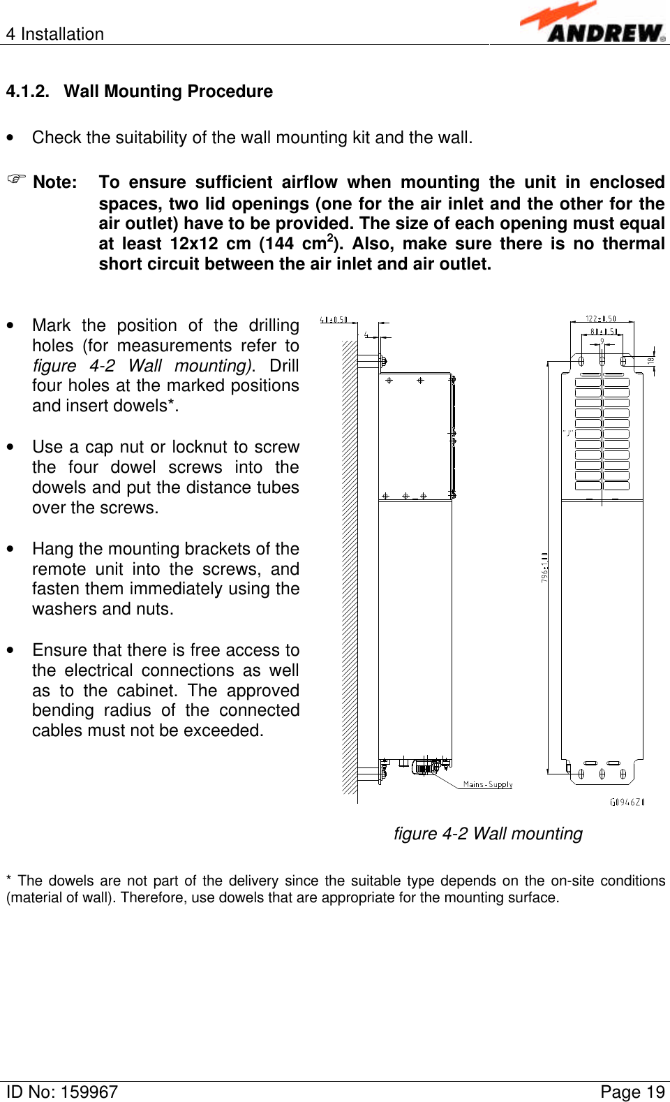
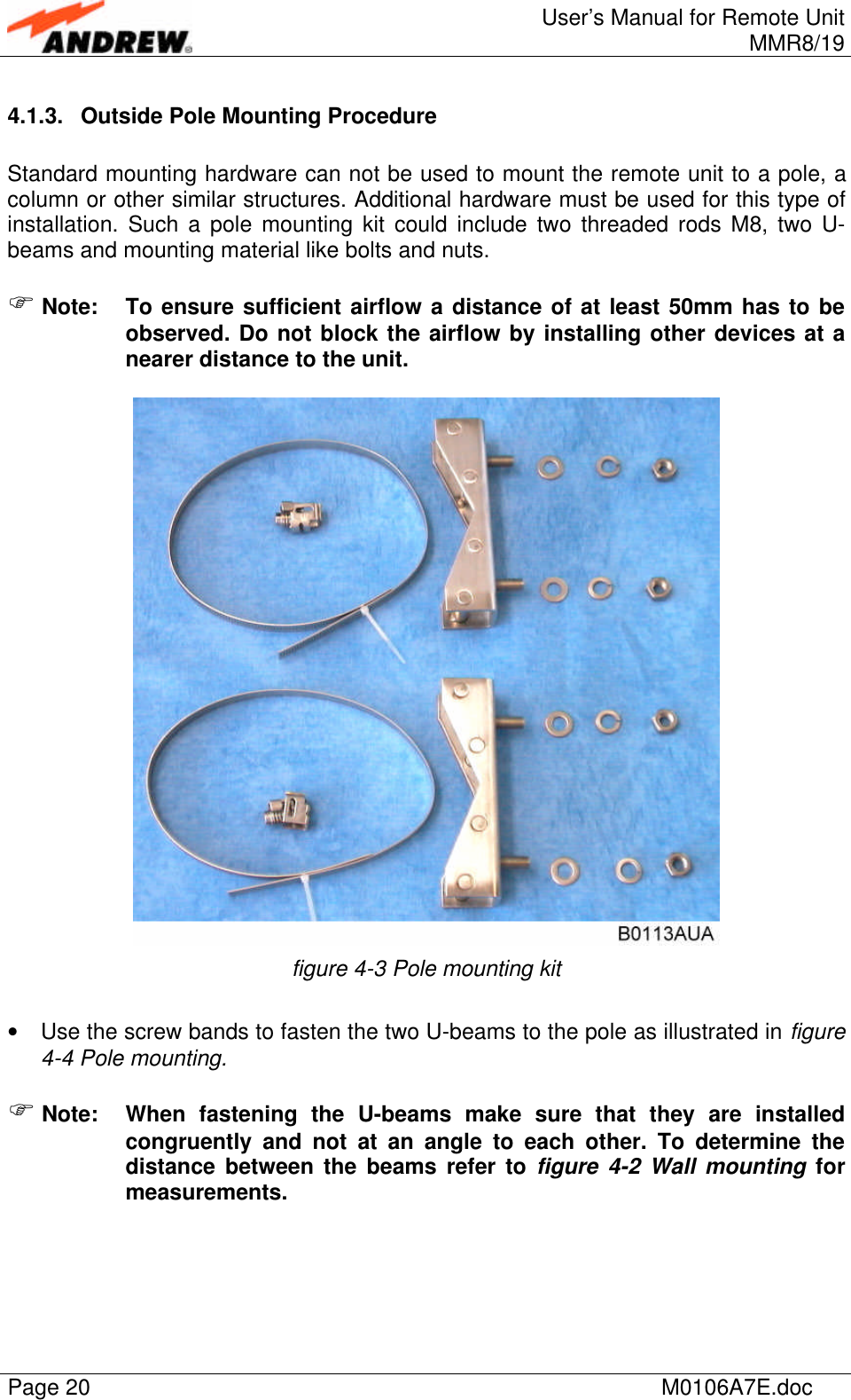
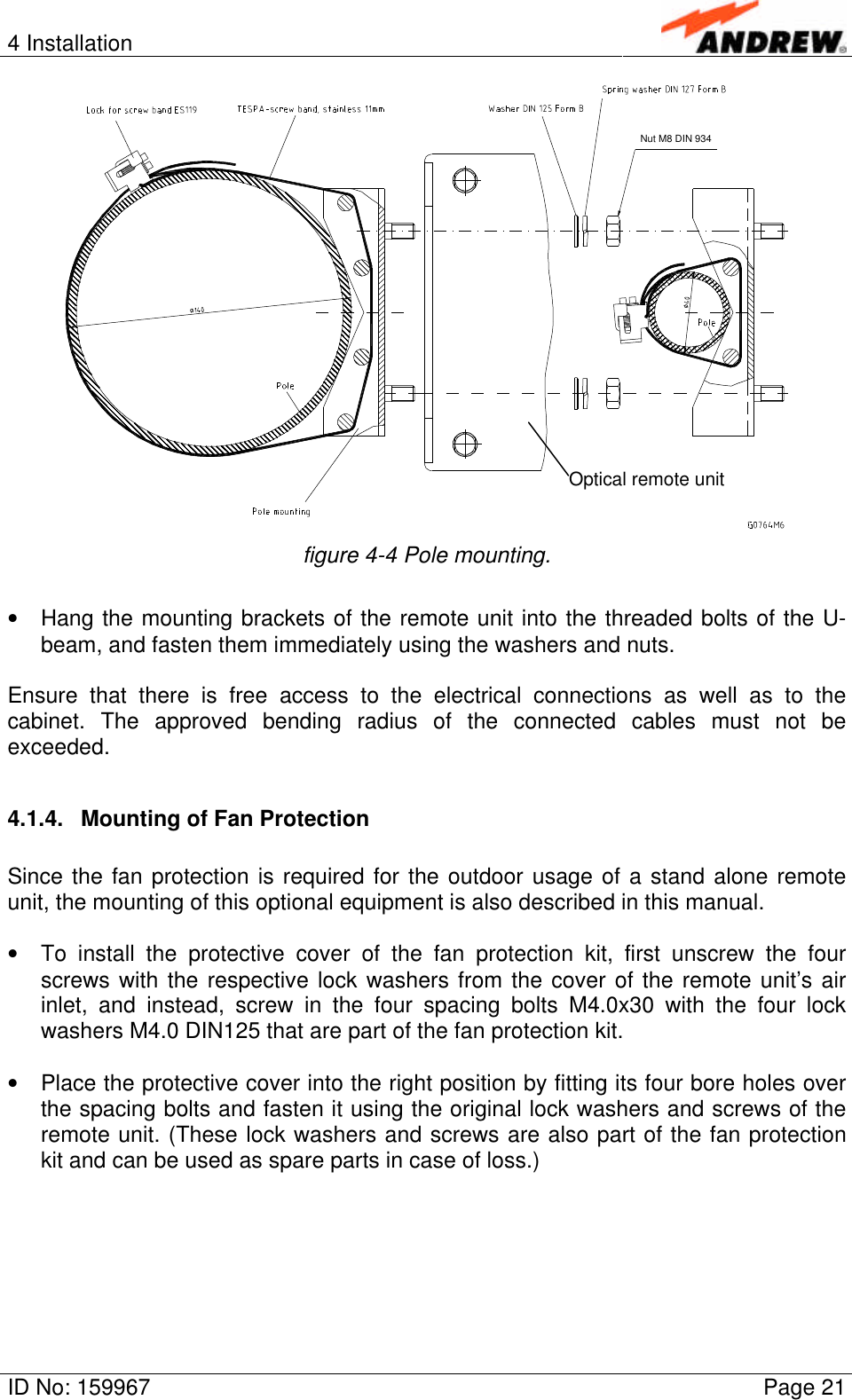
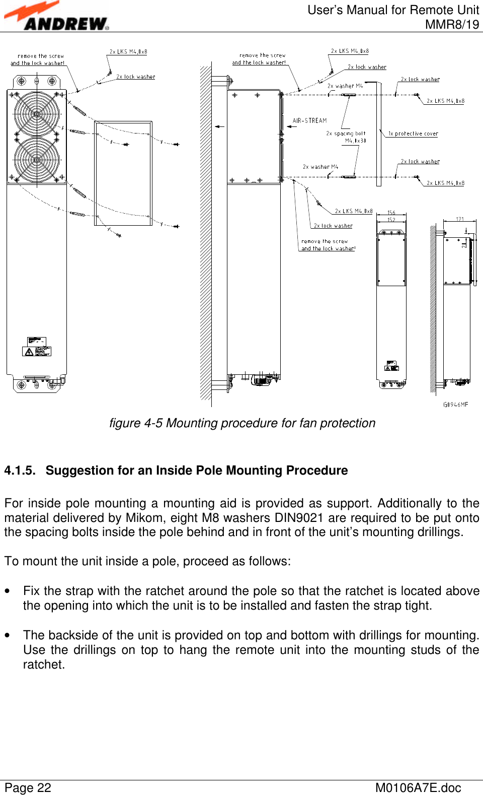
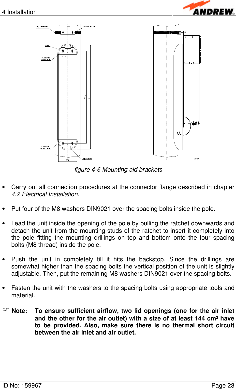
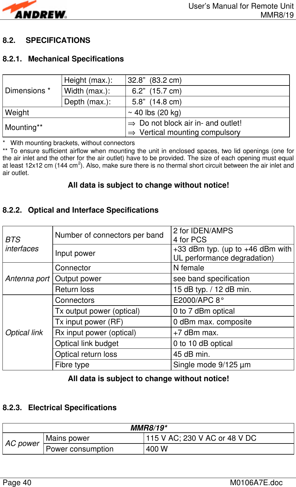
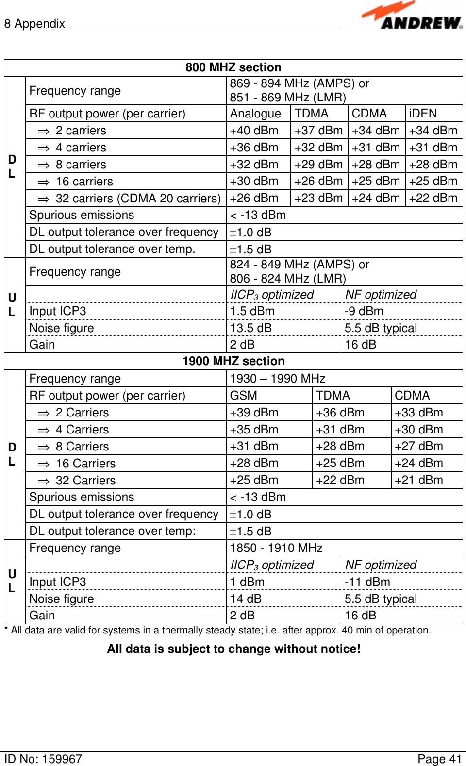
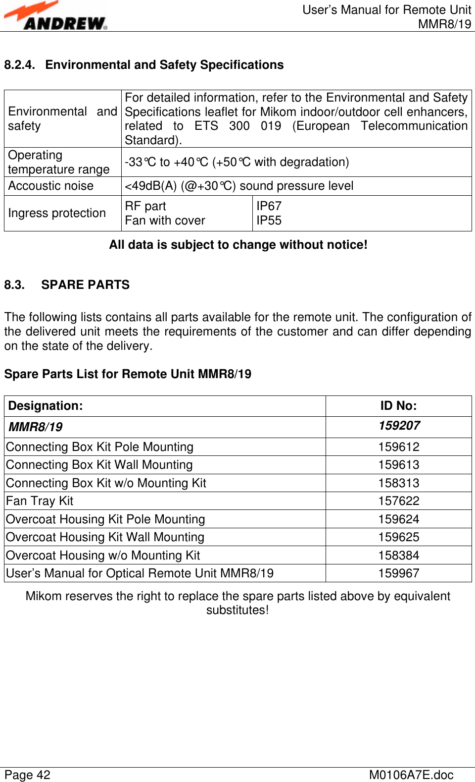
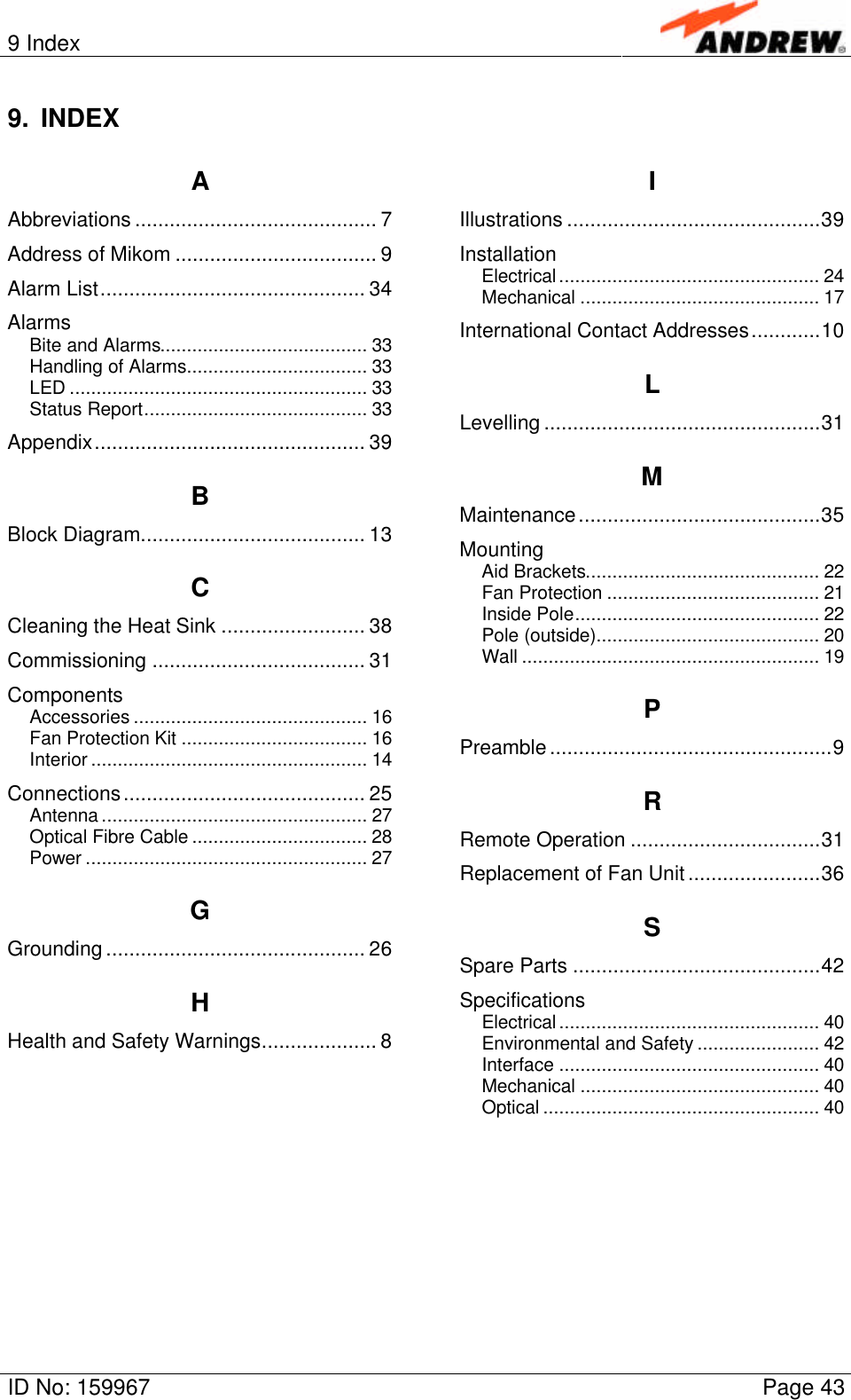
Andrew Wireless Innovations Group RPT-MMR8-19I Broad Band Repeater User Manual M0106A7E
Andrew Wireless Innovations Group Broad Band Repeater M0106A7E
UserManual.wiki
>
Andrew Wireless Innovations Group
>
RPT MMR8 19I User Manual
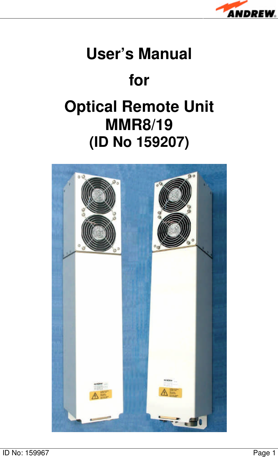
Users Manual
Navigation menu
Upload a User Manual
Namespaces
Wiki Guide
HTML
PDF
Info
Views
User Manual
Discussion / Help
Navigation