Andrew Wireless Innovations Group RPT-MMR8-19I Broad Band Repeater User Manual M0106A7E
Andrew Wireless Innovations Group Broad Band Repeater M0106A7E
Users Manual
ID No: 159967 Page 1
User’s Manual
for
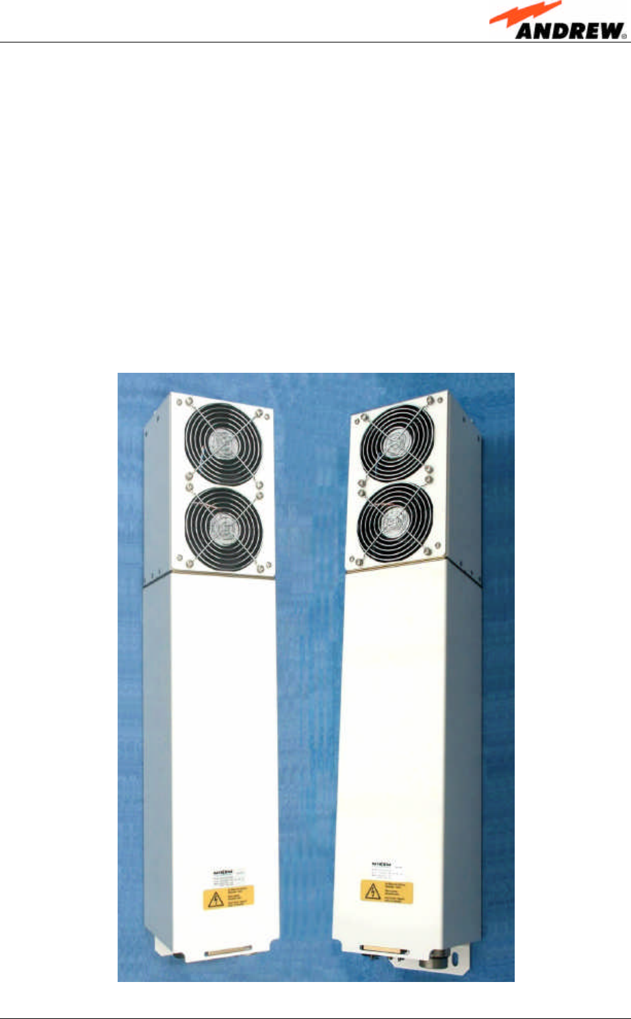
Optical Remote Unit
MMR8/19
(ID No 159207)

User’s Manual for Remote Unit
MMR8/19
Page 2M0106A7E.doc
Copyright 2003 Mikom GmbH
All rights reserved.
All information contained in this manual has been revised thoroughly. Yet Mikom
accepts no liability for any omissions or faults.
Mikom reserves the right to change all hard- and software characteristics without
notice.
Names of products mentioned herein are used for identification purposes only and
may be trademarks and/or registered trademarks of their respective companies.
No parts of this publication may be reproduced, stored in a retrieval system,
transmitted in any form or by any means, electronical, mechanical photocopying,
recording or otherwise, without prior written permission of the publisher.
Mikom GmbH An Andrew Company, 21-August-2003

ID No: 159967 Page 3
TABLE OF CONTENTS
1. GENERAL 7
1.1. USED ABBREVIATIONS 7
1.2. HEALTH AND SAFETY WARNINGS 8
1.3. PREAMBLE 9
1.4. INTERNATIONAL CONTACT ADDRESSES 10
2. INTRODUCTION 11
2.1. PURPOSE 11
2.2. THE MMR8/19 11
3. FUNCTIONAL DESCRIPTION 13
3.1. GENERAL 13
3.2. COMPONENTS OF THE MMR8/19 REMOTE UNIT 14
3.2.1. Components Inside the Unit 14
3.2.2. Fan Protection Kit 16
3.2.3. Accessories 16
4. INSTALLATION 17
4.1. MECHANICAL INSTALLATION 17
4.1.1. General 17
4.1.2. Wall Mounting Procedure 19
4.1.3. Outside Pole Mounting Procedure 20
4.1.4. Mounting of Fan Protection 21
4.1.5. Suggestion for an Inside Pole Mounting Procedure 22
4.2. ELECTRICAL INSTALLATION 24
4.2.1. General 24
4.2.2. Connections 25
4.2.3. Grounding 26
4.2.4. Power Connection 27
4.2.5. Connection of the Antenna Cables 27
4.2.6. Optical Fibre Cable Connection 28
5. COMMISSIONING 31
5.1. GENERAL 31
5.2. AUTO-LEVELLING 31
5.3. REMOTE OPERATION31

User’s Manual for Remote Unit
MMR8/19
Page 4M0106A7E.doc
6. ALARMS 33
6.1. BITE AND ALARMS 33
6.2. HANDLING OF ALARMS 33
6.3. STATUS REPORT 33
6.4. LED ALARMS 33
6.5. ALARM LIST 34
7. MAINTENANCE 35
7.1. GENERAL 35
7.2. REPLACING THE FAN UNIT 36
7.3. CLEANING THE HEAT SINK 38
8. APPENDIX 39
8.1. ILLUSTRATIONS 39
8.2. SPECIFICATIONS 40
8.2.1. Mechanical Specifications 40
8.2.2. Optical and Interface Specifications 40
8.2.3. Electrical Specifications 40
8.2.4. Environmental and Safety Specifications 42
8.3. SPARE PARTS 42
9. INDEX 43

ID No: 159967 Page 5
FIGURES AND TABLES
figure 3-1 Configuration of a MMR8/19 remote unit.................................................. 13
figure 3-2 Remote unit, front view ............................................................................. 14
figure 3-3 Remote unit, backside .............................................................................. 14
figure 3-4 Remote unit, left side ................................................................................ 15
figure 3-5 Remote unit, right side.............................................................................. 15
figure 4-1 Tube installation........................................................................................ 18
figure 4-2 Wall mounting........................................................................................... 19
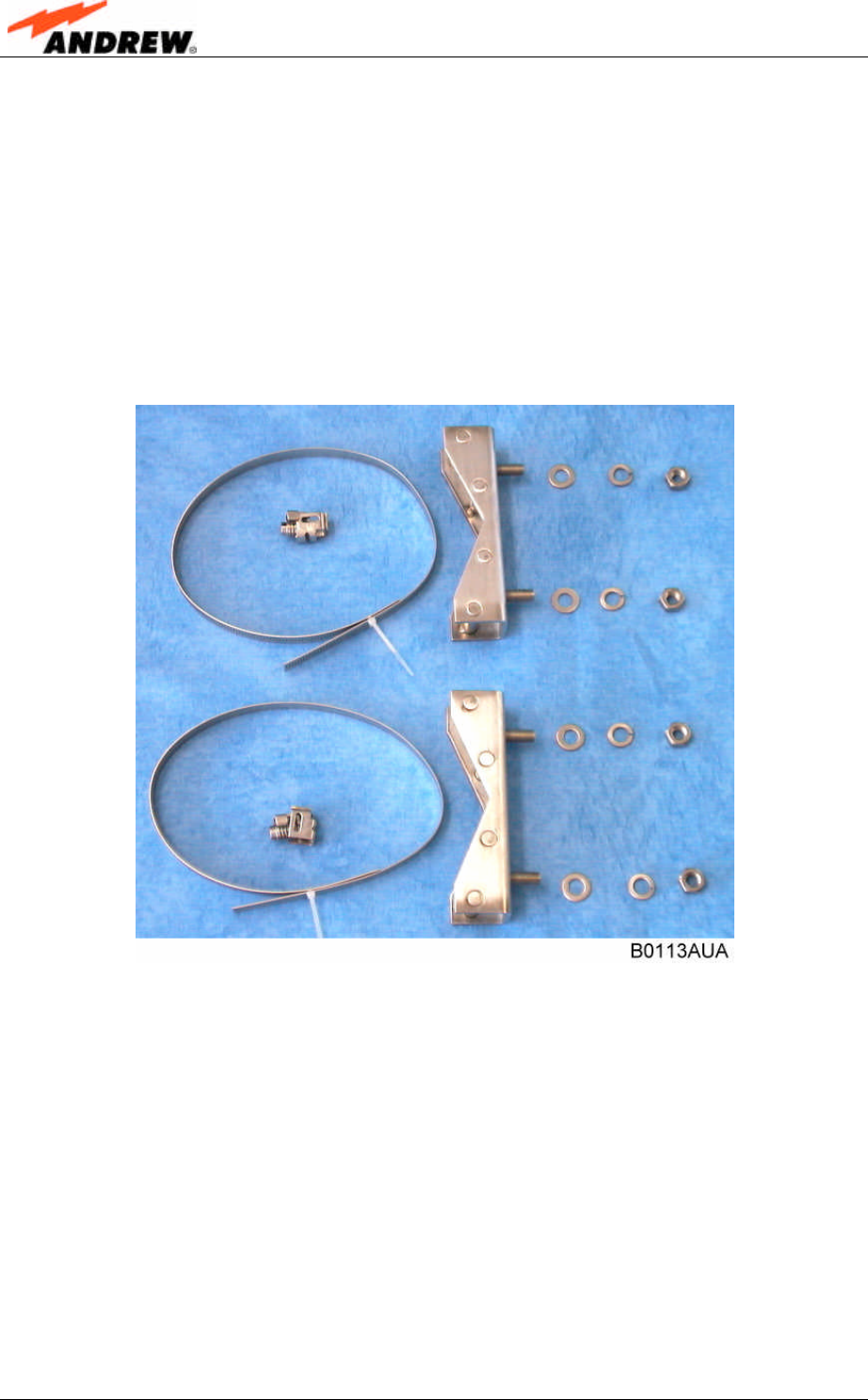
figure 4-3 Pole mounting kit ...................................................................................... 20
figure 4-4 Pole mounting........................................................................................... 21
figure 4-5 Mounting procedure for fan protection ...................................................... 22
figure 4-6 Mounting aid brackets............................................................................... 23
figure 4-7 Connector flange ...................................................................................... 25
figure 4-8 Grounding bolt with loosened hex nut....................................................... 26
figure 4-9 Grounding bolt, schematic view................................................................ 26
figure 4-10 Tight kit ................................................................................................... 29
figure 7-1 Fan unit assembly..................................................................................... 37
figure 8-1 Installation drawing ................................................................................... 39
table 1-1 List of international contact addresses....................................................... 10
table 4-1 Specified torques ....................................................................................... 17
table 6-1 LED alarms ................................................................................................ 33

User’s Manual for Remote Unit
MMR8/19
Page 6M0106A7E.doc
For your notes

1 General
ID No: 159967 Page 7
1. GENERAL
1.1. USED ABBREVIATIONS
ALC Automatic Level Control
AMPS American Mobile Phone System or Advanced Mobile Phone System
APAC Automatic Power Adjustment Circuit
BCCH Broadcast Control Channel
BITE Built In Test Equipment
BTS Base Transceiver Station
CDMA Code Division Multiple Access
CEPT Conférénce Européenne des Postes et Télécommunications
CF Center Frequency
CFO Center Frequency Offset
DL Downlink
EDGE Enhanced Data Rates for GSM Evolution
ESD Electrostatic Discharge
ETACS Enhanced TACS
ETS European Telecommunication Standard
ETSI European Telecommunication Standards Institute
FSK Frequency Shift Keying
GSM Global System for Mobile Communication
I2C-Bus Inter Integrated Circuit Bus (Philips)
ID No Identification Number
IF Intermediate Frequency
LMT Local Maintenance Terminal
MOR Mikom Optical Remote unit
MS Mobile Station
OMC Operation and Maintenance Center
PCMCIA Personal Computer Modem Communication International Association
PCS Personal Communication System
PSTN Public Switched Telephone Network
Rev Revision
RF Radio Frequency
RLP Radio Link Protocol
RSSI Receive Signal Strength Indication
RTC Real Time Clock
RX Receiver
SCL Serial Clock
SDA Serial Data
TACS Total Access Communication System
TCH Traffic Channel
TDMA Time Division Multiple Access
TX Transmitter
UL Uplink
UMTS Universal Mobile Telecommunication System
UPS Uninterruptable Power Supply
VSWR Voltage Standing Wave Ratio
User’s Manual for Remote Unit
MMR8/19
Page 8M0106A7E.doc
1.2. HEALTH AND SAFETY WARNINGS
1. Only suitably qualified personnel is allowed to work on this unit and only after
becoming familiar with all safety notices, installation, operation and maintenance
procedures contained in this manual.
2. Read and obey all the warning labels attached to the unit. Make sure that the
warning labels are kept in a legible condition and replace any missing or
damaged labels.
3. Obey all general and regional installation and safety regulations relating to work
on high voltage installations, as well as regulations covering correct use of tools
and personal protective equipment.
4. Keep operating instructions within easy reach and make them available to all
users.
5. It is the responsibility of the network provider to implement prevention measures
to avoid health hazards which may be associated to radiation from the antenna(s)
connected to the unit.
6. Make sure, access is restricted to qualified personnel.
7. Use this equipment only for the purpose specified by the manufacturer. Do not
carry out any modifications or fit any spare parts which are not sold or
recommended by the manufacturer. This could cause fires, electric shock or other
injuries.
8. Due to power dissipation, the remote unit may reach a very high temperature.
9. Before opening the unit or (dis-)connecting the mains connector at the remote
unit, ensure that mains supply is disconnected.
10. ESD precautions must be observed! Before commencing maintenance work, use
the available grounding system to connect ESD protection measures.
11. This unit complies with European standard EN60950.
12. Make sure the system settings are according to the intended use (see also
product information of manufacturer) and regulatory requirements are met.
13. Although the remote unit is internally protected against overvoltage, it is strongly
recommended to earth the antenna cables close to the remote unit’s antenna
connectors for protection against atmospheric discharge.
14. Laser radiation – Class 1! Do not stare into the beam, do not view it directly or
with optical instruments.

1 General
ID No: 159967 Page 9
1.3. PREAMBLE
Mikom An Andrew Company is a leading manufacturer of coverage equipment for
mobile radio networks, specializing in low cost, high performance, RF and optical
repeaters. Our optical distributed networks and RF repeater systems provide
coverage for every application: outdoor use, indoor installations, tunnels, subways
and many more.
Mikom has engineering and manufacturing facilities in Germany, Italy and the USA.
In addition, it maintains many field engineering offices throughout the world.
Mikom GmbH operates a quality management system which complies with the
requirements of ISO 9001. All equipment is manufactured using only highly reliable
materials. In order to ensure constant first-rate quality of the products, a
comprehensive quality assurance has been conducted at all fabrication stages. Every
component leaves the factory only after a thorough final acceptance test,
accompanied by a test certificate guaranteeing optimal function.
The declaration of conformity for the product is available on request via the local
offices or from Mikom directly.
Any intervention must be carried out by authorized persons only. If technical
assistance for the product is required, please contact the local office or Mikom
directly at one of the following addresses:
Mikom GmbH An Andrew Company
Industriering 10
86675 Buchdorf
Germany
Phone: +49 (0) 9099 69 0
Fax: +49 (0) 9099 69 930
email: WIsupport.germany@andrew.com
for The Americas:
Mikom US An Andrew Company
Phone: +1 (919) 771-2570
email: WIsupport.us@andrew.com
When set-up is performed according to this manual, the system will operate without
complications for a significant length of time.

User’s Manual for Remote Unit
MMR8/19
Page 10 M0106A7E.doc
1.4. INTERNATIONAL CONTACT ADDRESSES
in Australia
6 Stuart Street
Padstow NSW 2211
Australia
Phone: +61 (2) 9774-4200
Fax: +61 (2) 9774-4500
email:
WIsupport.australia@andrew.com
in France
Z.I. des Ebisoires
78370 Plaisir
France
Phone: +33 (1)30-79-15-36
Fax: +33 (1) 30-55-55-37
email:
WIsupport.france@andrew.com
in the USA
108 Rand Park Drive
Garner
NC 27529
USA
Phone: +1 (919) 771-2570
Fax: + 1 (919) 771-
email:
WIsupport.us@andrew.com
in the UK
Guildgate House
Pelican Lane
Newbury
RG14 1NX, Berkshire, U.K.
Phone: +44 (1635) 569-695
Fax: +44 (1635) 569-463
email:
WIsupport.uk@andrew.com
in China
Ground Floor, Unit F, Tower 2
The Astoria 198 Argle Street,
Mau Tau Wai, Kowloon
Hongkong
Phone: +852 2778 3187
Fax: +852 2778 3187
email:
WIsupport.china@andrew.com
in Canada
1815 Ironstone Manor, # 12
Pickering, Ontario L1W 3W9
Canada
Phone: +1 (905) 839-3474
Fax: +1 (905) 839-4663
email:
WIsupport.canada@andrew.com
in Switzerland
Tiergartenweg 1
4710 Balsthal
Switzerland
Phone: +41 (6238) 61260
Fax: +41 (6238) 61261
email:
WIsupport.switzerland@andrew.com
in Italy
Via De Crescenzi 40
48018 Faenza
Italy
Phone: +39 0546 697111
Fax: +39 0546 682768
email:
WIsupport.italia@andrew.com
in Austria
Weglgasse 10
2320 Schwechat
Austria
Phone: +43 (1) 706 – 3999
Fax: +43 (1) 706 – 39999
email:
WIsupport.austria@andrew.com
in Czech Republic
U Morusi 888
530 06 Pardubice-Svitkov
Czech. Republic
Phone: +42 (0406) 301280
Fax: +42 (0406) 301298
email:
WIsupport.czechrep@andrew.com
table 1-1 List of international contact addresses

2 Introduction
ID No: 159967 Page 11
2. INTRODUCTION
2.1. PURPOSE
Cellular telephone systems transmit signals in two directions between base
transceiver station (BTS) and mobile stations (MS) within the signal coverage area.
If weak signal transmissions occur within the coverage area because of indoor
applications, topological conditions or distance from the transmitter, extension of the
transmission range can be achieved by means of an optical distribution system.
Such a system contains an optical master unit and several remote units. The number
of the remote units depends on the hardware and software configuration. The remote
units are connected to the master unit with optical links. The optical loss must be less
than 10 dB inclusive optical couplers or splitters.
The master unit is the connection to the BTS. The configuration of a master unit
depends on the number of the remote units and the frequency range.
The optical transmission uses WDM-systems with a wavelength of 1550 nm in the
uplink and 1310 nm in the downlink.
2.2. THE MMR8/19
The fibre optic distribution system is designed for AMPS/PCS or iDEN/PCS services.
Up to two bands can be transmitted. In future applications each fibre will be able to
serve up to four remote units and to operate up to four providers. One master unit
can operate up to 124 remote units.
An auto-levelling function for compensating different fibre losses and a
comprehensive supervision concept are implemented.
The remote unit MMR8/19 is connected to a central master unit through optical fibre
lines. Specific customer designs for lamp pole or wall mounting are available. Thus,
the system provides many advantages in view of easy site acquisition.

User’s Manual for Remote Unit
MMR8/19
Page 12 M0106A7E.doc
For your notes
3 Functional Description
ID No: 159967 Page 13
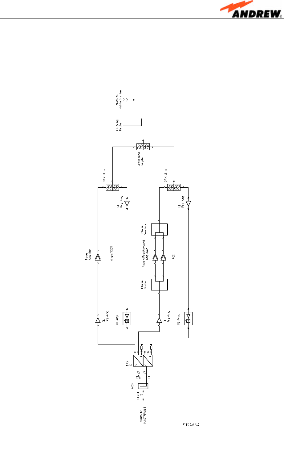
3. FUNCTIONAL DESCRIPTION
3.1. GENERAL
The following figure shows the configuration of a MMR8/19 remote unit.
figure 3-1 Configuration of a MMR8/19 remote unit
User’s Manual for Remote Unit
MMR8/19
Page 14 M0106A7E.doc
3.2. COMPONENTS OF THE MMR8/19 REMOTE UNIT
The actual configuration of the remote unit can be seen at the configuration list which
is part of the delivery.
3.2.1. Components Inside the Unit
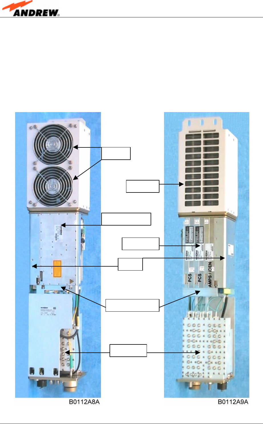
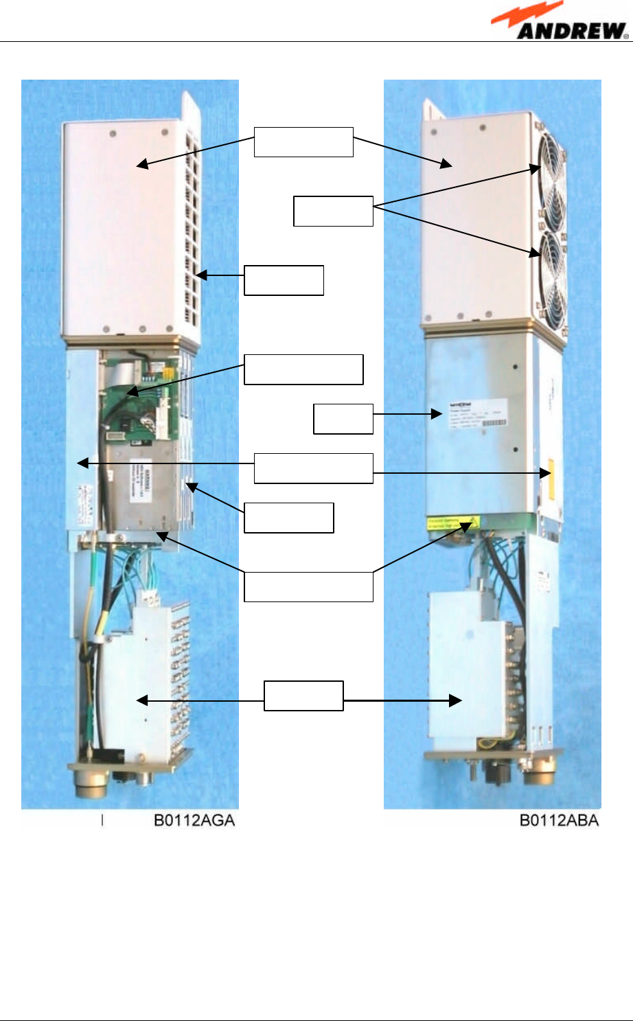
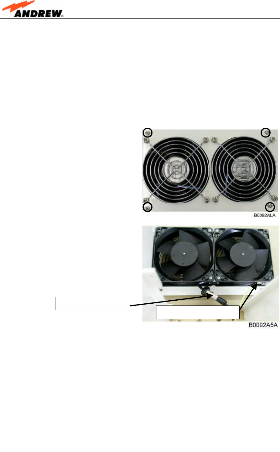
The following figures show exemplary views of an MMR8/19 remote unit – except for
the fan housing without cover – to illustrate the individual components.
figure 3-2 Remote unit, front view figure 3-3 Remote unit, backside
Air inlet
Air outlet
Optical module
Amplifiers
Distribution unit
Duplexer
PSU
3 Functional Description
ID No: 159967 Page 15
figure 3-4 Remote unit, left side figure 3-5 Remote unit, right side
Air inlet
Fan housing
Optical module
PSU
Amplifiers
Distribution unit
Duplexer
Control module
Air outlet

User’s Manual for Remote Unit
MMR8/19
Page 16 M0106A7E.doc
3.2.2. Fan Protection Kit
In order to protect the fan unit (e.g. against rain), a protective cover to be mounted
over the air inlet is delivered for standalone pole or wall mounted units. For inside
pole mounting this equipment is not required.
For more details see chapter 4.1.4 Mounting of Fan Protection.
3.2.3. Accessories
For the accessories available for the MMR remote unit, e.g. overcoat housing,
connecting box or iso-trafo kit, a separate manual is available.
4 Installation
ID No: 159967 Page 17
4. INSTALLATION
4.1. MECHANICAL INSTALLATION
4.1.1. General
Read the health and safety warnings in chapter 1.2 Health and Safety Warnings.
1. Do not install the unit in a way or at a place where the specifications
outlined in the Environmental and Safety Specifications leaflet of Mikom are
not met.
2. It is strongly recommended to install the unit vertically with the fan unit at
the top. If a different installation of the remote unit is required, please
contact customer service for further information.
3. It is recommended only to use the mounting hardware delivered by Mikom.
If different mounting hardware is used, the specifications for stationary use
of the remote unit must not be exceeded.
F Note: Exceeding the specified load limits may cause the loss of warranty!
4. The unit is considerably heavy. Make sure that a suitable mounting
surface is used. Ensure there is adequate manpower to handle the weight of
the system.
5. Due to power dissipation, the remote unit may reach a very high
temperature. Ensure sufficient airflow for ventilation as specified in the
individual mounting procedures.
If any different or additional mounting material is used, ensure that the mounting
remains as safe as the mounting designed by Mikom. Ensure that the static and
dynamic strengths are adequate for the environmental conditions of the site. The
mounting itself must not vibrate, swing or move in any way that might cause damage
to the remote unit.
Specified torques have to be observed for certain mounting procedures according to
the following table:
Type Tallow-drop
screws Hex
nuts Spacing bolts PG
(plastic) PG
(aluminium)
Thread M 4 M 8 M 4 M 8 PG 13,5 PG 29
Specified
torques 3.3 Nm 27 Nm 2.3 Nm 27 Nm 3.75 Nm 10 Nm
table 4-1 Specified torques
User’s Manual for Remote Unit
MMR8/19
Page 18 M0106A7E.doc
F Note: To avoid damage when mounting the unit, always make sure that
the M8 washers (DIN9021 or DIN125 depending on the mounting kit)
are placed behind and in front of the unit’s mounting drillings.
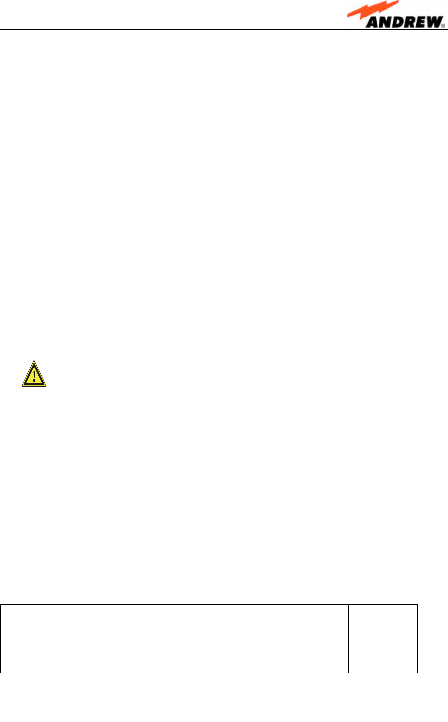
For the installation of the protective tube that is delivered with the MMR remote unit
for the protection of the fibre-optic cables, observe that a section of at least 250 mm
at the tube end has to point downwards as illustrated below.
figure 4-1 Tube installation
The mounting procedures for a stand alone remote unit without optional accessories
are described and illustrated in the following sections. For further information
regarding special mounting procedures including mounting of accessory equipment,
please see separate manual.
4 Installation
ID No: 159967 Page 19
4.1.2. Wall Mounting Procedure
• Check the suitability of the wall mounting kit and the wall.
F Note: To ensure sufficient airflow when mounting the unit in enclosed
spaces, two lid openings (one for the air inlet and the other for the
air outlet) have to be provided. The size of each opening must equal
at least 12x12 cm (144 cm2). Also, make sure there is no thermal
short circuit between the air inlet and air outlet.
• Mark the position of the drilling
holes (for measurements refer to
figure 4-2 Wall mounting). Drill
four holes at the marked positions
and insert dowels*.
• Use a cap nut or locknut to screw
the four dowel screws into the
dowels and put the distance tubes
over the screws.
• Hang the mounting brackets of the
remote unit into the screws, and
fasten them immediately using the
washers and nuts.
• Ensure that there is free access to
the electrical connections as well
as to the cabinet. The approved
bending radius of the connected
cables must not be exceeded.
figure 4-2 Wall mounting
* The dowels are not part of the delivery since the suitable type depends on the on-site conditions
(material of wall). Therefore, use dowels that are appropriate for the mounting surface.
User’s Manual for Remote Unit
MMR8/19
Page 20 M0106A7E.doc
4.1.3. Outside Pole Mounting Procedure
Standard mounting hardware can not be used to mount the remote unit to a pole, a
column or other similar structures. Additional hardware must be used for this type of
installation. Such a pole mounting kit could include two threaded rods M8, two U-
beams and mounting material like bolts and nuts.
F Note: To ensure sufficient airflow a distance of at least 50mm has to be
observed. Do not block the airflow by installing other devices at a
nearer distance to the unit.
figure 4-3 Pole mounting kit
• Use the screw bands to fasten the two U-beams to the pole as illustrated in figure
4-4 Pole mounting.
F Note: When fastening the U-beams make sure that they are installed
congruently and not at an angle to each other. To determine the
distance between the beams refer to figure 4-2 Wall mounting for
measurements.
4 Installation
ID No: 159967 Page 21
Nut M8 DIN 934
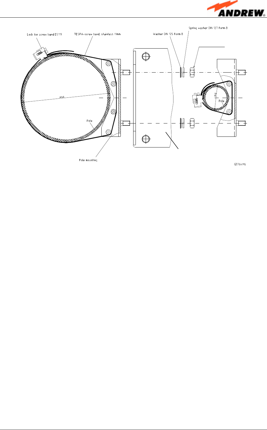
figure 4-4 Pole mounting.
• Hang the mounting brackets of the remote unit into the threaded bolts of the U-
beam, and fasten them immediately using the washers and nuts.
Ensure that there is free access to the electrical connections as well as to the
cabinet. The approved bending radius of the connected cables must not be
exceeded.
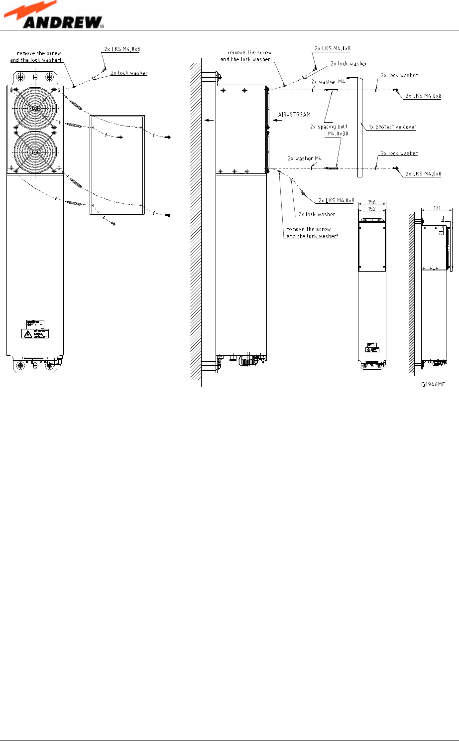
4.1.4. Mounting of Fan Protection
Since the fan protection is required for the outdoor usage of a stand alone remote
unit, the mounting of this optional equipment is also described in this manual.
• To install the protective cover of the fan protection kit, first unscrew the four
screws with the respective lock washers from the cover of the remote unit’s air
inlet, and instead, screw in the four spacing bolts M4.0x30 with the four lock
washers M4.0 DIN125 that are part of the fan protection kit.
• Place the protective cover into the right position by fitting its four bore holes over
the spacing bolts and fasten it using the original lock washers and screws of the
remote unit. (These lock washers and screws are also part of the fan protection
kit and can be used as spare parts in case of loss.)
Optical remote unit
User’s Manual for Remote Unit
MMR8/19
Page 22 M0106A7E.doc
figure 4-5 Mounting procedure for fan protection
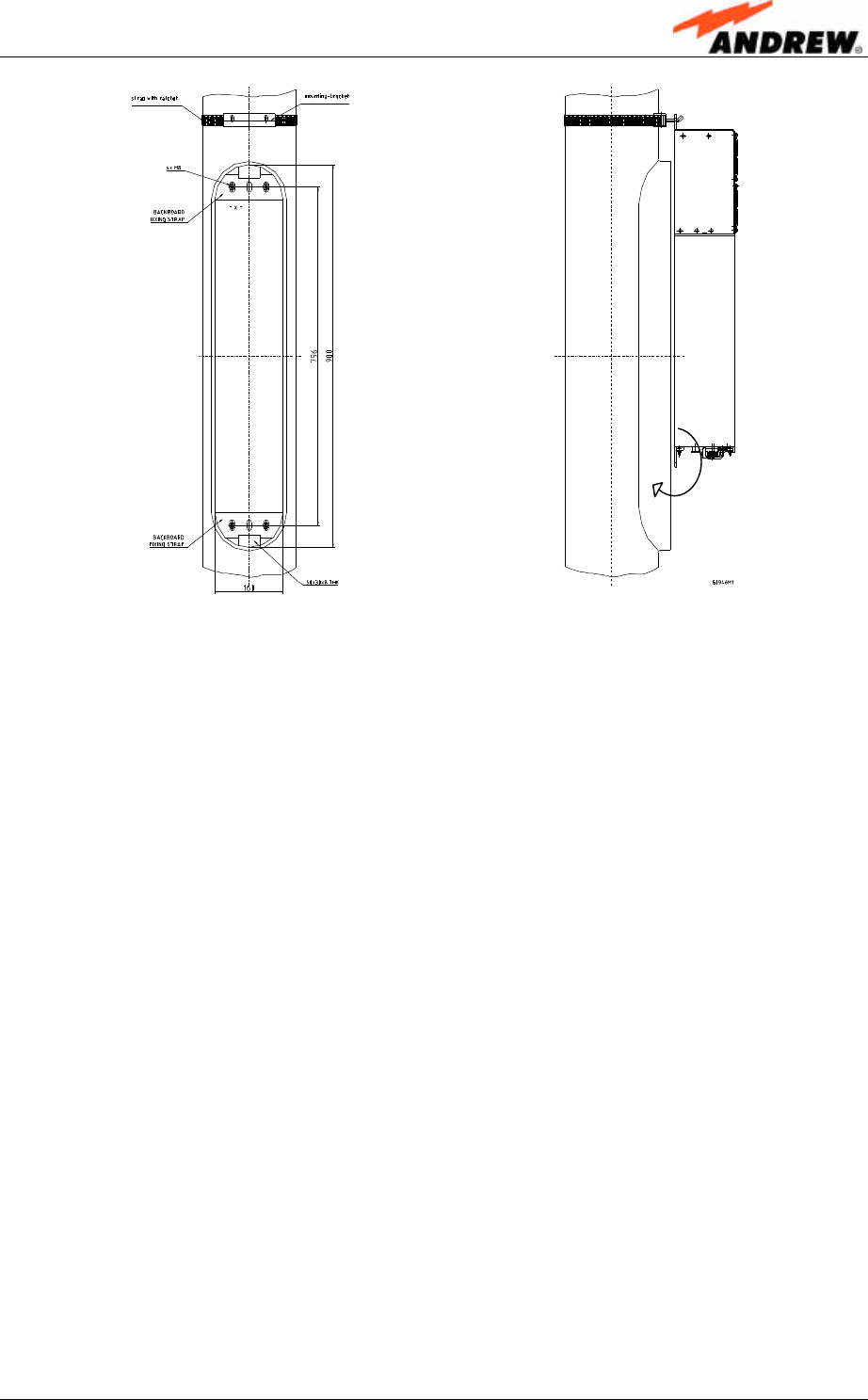
4.1.5. Suggestion for an Inside Pole Mounting Procedure
For inside pole mounting a mounting aid is provided as support. Additionally to the
material delivered by Mikom, eight M8 washers DIN9021 are required to be put onto
the spacing bolts inside the pole behind and in front of the unit’s mounting drillings.
To mount the unit inside a pole, proceed as follows:
• Fix the strap with the ratchet around the pole so that the ratchet is located above
the opening into which the unit is to be installed and fasten the strap tight.
• The backside of the unit is provided on top and bottom with drillings for mounting.
Use the drillings on top to hang the remote unit into the mounting studs of the
ratchet.
4 Installation
ID No: 159967 Page 23
figure 4-6 Mounting aid brackets
• Carry out all connection procedures at the connector flange described in chapter
4.2 Electrical Installation.
• Put four of the M8 washers DIN9021 over the spacing bolts inside the pole.
• Lead the unit inside the opening of the pole by pulling the ratchet downwards and
detach the unit from the mounting studs of the ratchet to insert it completely into
the pole fitting the mounting drillings on top and bottom onto the four spacing
bolts (M8 thread) inside the pole.
• Push the unit in completely till it hits the backstop. Since the drillings are
somewhat higher than the spacing bolts the vertical position of the unit is slightly
adjustable. Then, put the remaining M8 washers DIN9021 over the spacing bolts.
• Fasten the unit with the washers to the spacing bolts using appropriate tools and
material.
F Note: To ensure sufficient airflow, two lid openings (one for the air inlet
and the other for the air outlet) with a size of at least 144 cm² have
to be provided. Also, make sure there is no thermal short circuit
between the air inlet and air outlet.

User’s Manual for Remote Unit
MMR8/19
Page 24 M0106A7E.doc
4.2. ELECTRICAL INSTALLATION
4.2.1. General
Read the health and safety warnings in chapter 1.2 Health and Safety Warnings.
1. This unit contains dangerous voltages. Loss of life, severe personal injury or
property damage can be the result if the instructions contained in this manual are
not followed.
2. It is compulsory to ground the unit before connecting power supply. A grounding
bolt is provided on the cabinet to connect the ground bonding cable.
3. Although the remote unit is internally protected against overvoltage, it is strongly
recommended to earth the antenna cables close to the remote unit’s antenna
connectors for protection against atmospheric discharge. In areas with strong
lightning it is strongly recommended to insert additional lightning protection.
4. If the mains connector of the remote unit is not easily accessible, a separation
device in the mains circuit must be provided within easy reach.
5. Before connecting or disconnecting the mains connector at the remote unit,
ensure that mains supply is disconnected.
6. Make sure that an appropriate circuit breaker and an overcurrent limiting device
are connected between mains and remote unit.
7. A connection of mains supply to a power socket requires the power socket to be
nearby the remote unit.
8. The remote unit might be supplied from IT mains. (The maximum nominal line to
line voltage must not exceed 400VAC).
9. Incorrectly wired connections can destroy electrical and electronic components.
10. To avoid corrosion at the connectors caused by electrochemical processes, the
material of the cable connectors must not cause a higher potential difference than
0.6V (see electrochemical contact series).
11. It is sufficient to tighten the N antenna connector hand-screwed. Any use of a tool
(e.g. pair of pliers) might cause damage to the connector and thus lead to
malfunctioning of the remote unit.
12. For unstabilized electric networks which frequently generate spikes, it is advised
to use a voltage limiting device.
13. Observe the labels on the front panels before connecting or disconnecting any
cables.
4 Installation
ID No: 159967 Page 25
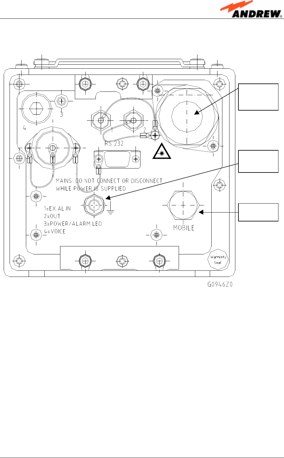
4.2.2. Connections
figure 4-7 Connector flange
Optical
fibre
connector
N-
connector
Grounding
bolt
User’s Manual for Remote Unit
MMR8/19
Page 26 M0106A7E.doc
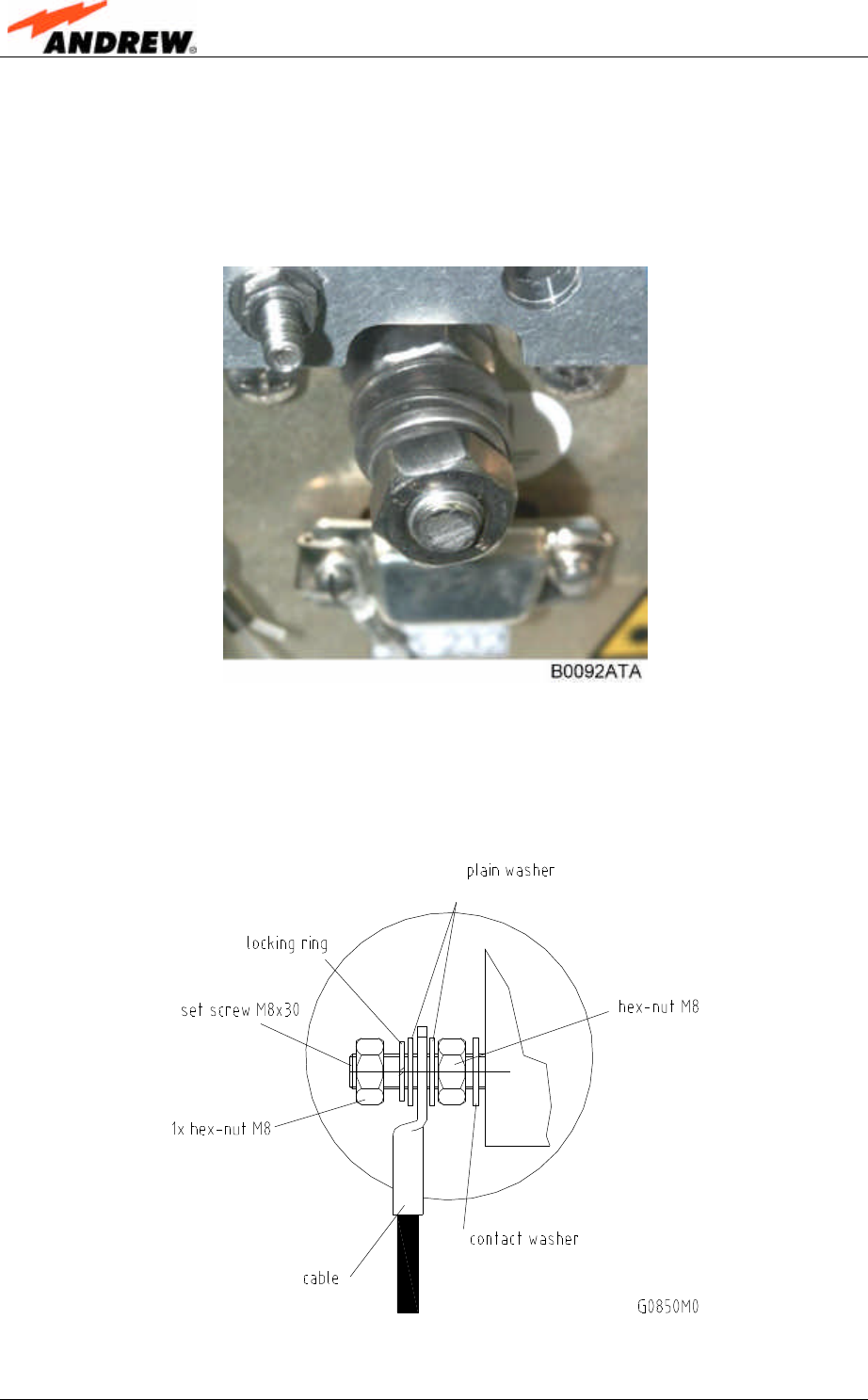
4.2.3. Grounding
Grounding must be carried out. Connect an earth bonding cable to the grounding
connection provided at the outside of the remote unit (see figure 4-7 Connector
flange). Do not use the grounding connection to connect external devices.
figure 4-8 Grounding bolt with loosened hex nut
After loosening the hex nut, connect the earth bonding cable between the two
washers as illustrated in the figures above and below. Then, fasten all parts again
with the hex nut.
figure 4-9 Grounding bolt, schematic view
4 Installation
ID No: 159967 Page 27
4.2.4. Power Connection
F Note: Do not connect the power cord at the mains connector (see figure
4-7 Connector flange) while power is applied, i. e. interrupt mains
supply before connecting the power cord at the remote unit. Then,
engage mains again.
Before connecting electrical power to the remote unit, the remote unit must be
grounded.
For power supply connection a minimum cross section of 1.5 mm2
for each wire has to be observed as well as the applicable national
regulations regarding loop impedance, voltage drop and methods
of installation. Ensure to connect to the right voltage.
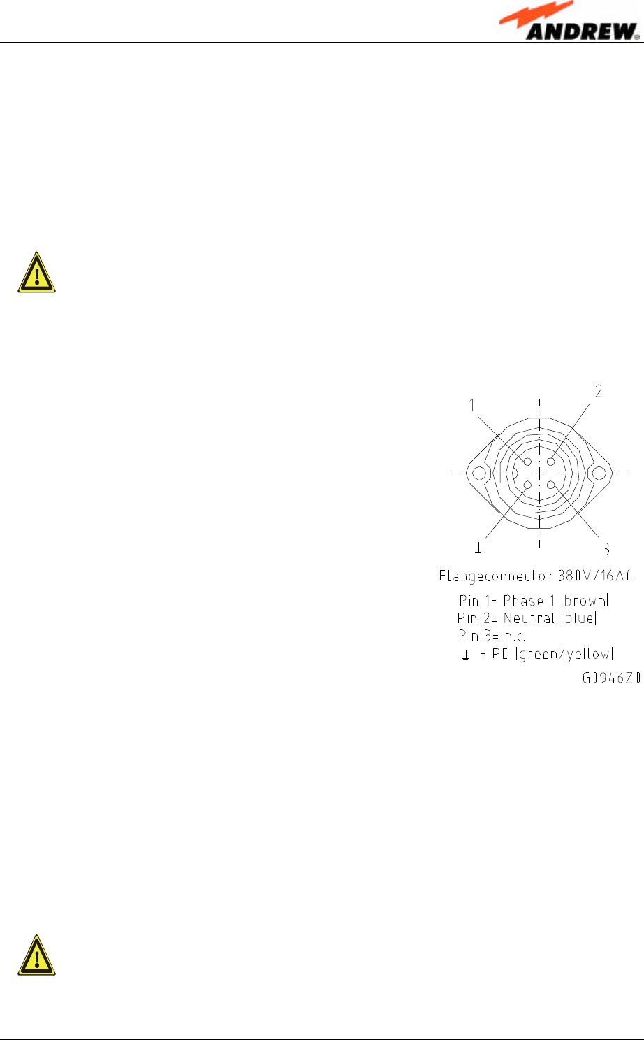
The correct wiring of the power supply plug is as follows:
4.2.5. Connection of the Antenna Cables
The remote unit has a N-type antenna connector. For its location please refer to
figure 4-7 Connector flange. For mounting the cable connectors, it is recommended
to refer to the corresponding documentation of the connector manufacturer. The
bending radius of the antenna cables must remain within the given specifications.
For the selection of cable and antenna it should be considered that a cable with
higher loss is less expensive but on the other hand it impairs performance.
It is sufficient to tighten the N connectors hand-tight. The use of a
tool (like pliers) may cause damage to the connector and
therefore, lead to a malfunctioning of the remote unit.

User’s Manual for Remote Unit
MMR8/19
Page 28 M0106A7E.doc
4.2.6. Optical Fibre Cable Connection
Optical signals are transmitted by use of an optical fibre for each remote unit.
F Note: Care should be taken when connecting and disconnecting fibre
optic cables. Scratches and dust significantly affect system
performance and may permanently damage the connector. Always
use protective caps on fibre optic connectors not in use.
In general optical fibres do not need special protective measures. However,
protection against environmental influences e.g. rodents and humidity must be
considered.
The optical fibre is a single mode fibre. Type is E9/125µm with the following minimum
requirements.
Attenuation: <0.36 dB/km @ 1310 nm /<0.26 dB/km @ 1550 nm
Dispersion: <3.5 ps/nm km @ 1310 nm /<18.0 ps/nm km @ 1550 nm
The specified bending radius of the optical fibres must not be exceeded. The pigtails
for the connection between master unit and remote unit must have a sufficient length.
A protection for the feeding into units must be given. The system attenuation of the
optical fibres, including the connectors, must not exceed 10 dB.
System attenuation and attenuation of optical components must be determined. This
can be achieved by measuring attenuation and reflection with an appropriate
measuring instrument. For pigtails, a total value of < 0.4 dB (measured to a reference
plug) can be assumed due to the dead zone of the reflectometer. These
measurements must be made with a sufficient length of optical fibre, at the In- and
Output of the device which has to be measured.
Fibre cable connectors have to be of the same type (E2000/APC8°) as the connec-
tors used for the unit. The fibre optic cables are connected to the optical transceiver.
F Note: Angled connectors are not compatible with straight optical
connectors; non-compatibility of connectors will result in
permanent damage to both connectors.
Before connecting the fibre cables, follow the procedure below to ensure optimized
performance. It is important that these procedures are carried out with care:
Ø Remove fibre optic protective caps.
Ø Do not bend the fibre optic cable in a tight radius (< 4 cm) as this may cause
cable damage and interrupt transmission.
4 Installation
ID No: 159967 Page 29
Ø Using high-grade alcohol and lint-free cotton cleaning swabs, clean the end of
the fibre optic cable that will be inserted in the optical connectors on the donor
interface box.
Ø Blow out the laser receptacle with clean and dry compressed air to remove
any particulate matter.
Ø Connect the fibre optic cables by inserting the cable end into the laser
receptacle and aligning the key (on the cable end) with the keyed slot.
Ø Do not use any index matching gels or fluids of any kind in these connectors.
Gels are intended for laboratory use and attract dirt in the field.
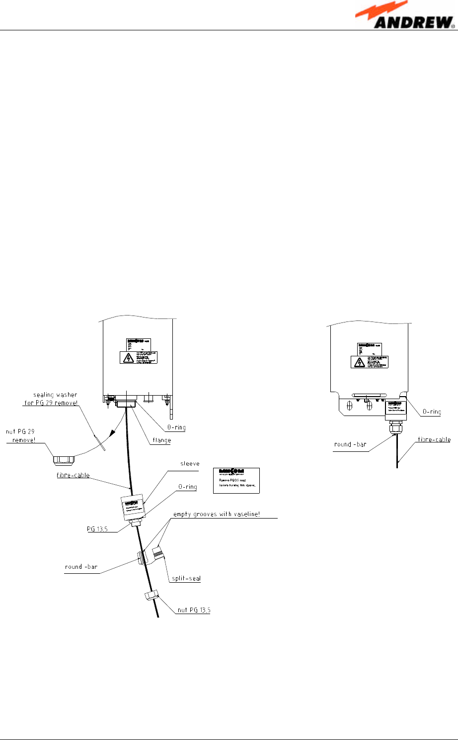
F Note: If the unit is mounted inside a pole (see separate description) the
following procedure has to be strictly observed:
G0946MC
figure 4-10 Tight kit

User’s Manual for Remote Unit
MMR8/19
Page 30 M0106A7E.doc
1. Remove the PG29 nut and the sealing washer.
2. Connect the optical fibre cable.
3. Screw the sleeve onto the flange.
4. Lay the fibre cable into the groove beside the round bar in one half of the split-
seal. à Ensure that in both halves the grooves for the fibre cable are filled with
vaseline.
5. Press the seal into the PG sleeve while holding the optical fibre straight.
6. Screw the PG13.5 nut tightly onto the PG13.5.

5 Commissioning
ID No: 159967 Page 31
5. COMMISSIONING
5.1. GENERAL
Read the health and safety warnings in chapter 1.2 Health and Safety Warnings as
well as the description carefully to avoid mistakes and proceed step by step as
described!
Ø Do not operate the remote unit without termination of the antenna connections!
The termination can be achieved by connecting the antennas, a dummy load
or the 50-Ohm-terminated connection of a measuring instrument.
Ø To ensure safety, the electrical and subsequent installations, commissioning
and maintenance activities that require the unit to be under power while open,
must only be carried out by suitably qualified personnel.
Ø When opening the remote unit, do not damage the seals on the devices inside
the remote unit. Warranty void if the seals are broken!
Ø To query the status, the remote unit can be accessed remotely via a master
unit.
Ø Since the system provides an auto-levelling and auto-setup function, no further
settings are necessary at the remote unit itself. All other settings are required
at the master unit and are explained in the corresponding documentation.
5.2. AUTO-LEVELLING
In order for the auto-levelling function to operate properly, a defined level has to be
set at the optical interface (DL) of the master unit. For details refer to the description
of the master unit.
5.3. REMOTE OPERATION
For details refer to the descriptions of the master unit and corresponding software.

User’s Manual for Remote Unit
MMR8/19
Page 32 M0106A7E.doc
For your notes

6 Alarms
ID No: 159967 Page 33
6. ALARMS
6.1. BITE AND ALARMS
The Built-In Test concept comprises the monitoring of the power supplies, the power
amplifiers and the optical interface.
All occurring alarms can be checked via software at the master unit.
6.2. HANDLING OF ALARMS
As soon as the software acknowledges a valid alarm, a message is transmitted to the
master unit.
If the reason for the alarm has been cleared or if the alarm should continue, a new
alarm message will not be repeated. If there was an interruption of at least one
second after acknowledgement, a new alarm message will be generated.
6.3. STATUS REPORT
For details refer to the corresponding software documentation, which is part of the
“System Description for the MMR Optical Master Unit”.
6.4. LED ALARMS
The LED on the connector flange of the remote unit indicates the following alarms:
LED Indication Alarms
Green No alarm à Status ok
Alarms not related to RU:
Orange • External alarms
• Optical alarm Rx
• all ALC alarms
Alarms related to RU:
Red • Power 28V
• Power 12V
• Temperature
• Fan
• I²C
• Optical alarm Tx
• Amplifier “Power Down”
LED off No power
table 6-1 LED alarms
For the position of the LED see figure 4-7 Connector flange.

User’s Manual for Remote Unit
MMR8/19
Page 34 M0106A7E.doc
6.5. ALARM LIST
The status of the remote unit can be checked via software commands.
Alarm message Failure
Opt. Rx alarm
Opt. Tx alarm Opt. Rx failure (no input)
Opt. Tx failure
Autolevelling Optical loss has changed
Amplifier current DL1
Amplifier current DL2
Amplifier current DL3 Amplifier current too high or too low
ALC alarm DL
ALC alarm UL Output power too high
Input power too high
Temperature alarm Temperature out of range
I2C bus failure Internal communication bus failure
PSU 12 V
PSU 28 V
PSU mains
Power supply 12V failure
Power supply 28V failure
Power supply mains failure
FAN FAN out of order
External alarm 1
External alarm 2
External alarm 3
External alarm 4
Option for supervision of external components

7 Maintenance
ID No: 159967 Page 35
7. MAINTENANCE
7.1. GENERAL
Read the health and safety warnings in chapter 1.2 Health and Safety Warnings.
F Note: The remote unit does not require preventative maintenance
measures.
F Note: To prevent malfunctions of the cooling system due to dirt or
pollution, it is recommended to clean the heat sink at regular
intervals. These cleaning intervals depend mainly on the location
of the remote unit and the corresponding degree of pollution.
Maintenance on the remote unit shall be performed by replacing only components
that are contained in this chapter. In order to maintain warranty, take care not to
damage unintentionally the seals on the modules.
The spare parts list, consequently, contains only units which can be replaced without
tuning or soldering work. Those units are all Mikom parts as well as internal and
external cables.
F Note: Defect parts should only be replaced by original parts from Mikom.
All interventions inside the housing are at one’s own risk.
F Note: During maintenance ensure that the remote unit has been
disconnected from mains.
F Note: Before disconnecting any cables, label any unlabeled cables to
ensure correct connection.
For most maintenance procedures appropriate tools are required to ensure correct
handling. All these tools can be ordered from Mikom. For screwing procedures
observe that all our screws have a right-hand thread, i. e. for fastening the screws
turn the tool clockwise and for unscrewing them turn it counter-clockwise.
Due to the design of the remote unit the only component recommended to be
replaced is the fan unit. For replacing any other component please contact Mikom.
User’s Manual for Remote Unit
MMR8/19
Page 36 M0106A7E.doc
7.2. REPLACING THE FAN UNIT
Replacement of the fan unit is not required as a preventative measure. Only if an
alarm indicates a malfunctioning of a fan, the unit has to be exchanged.
F Note: Please observe that the fan unit can only be replaced as a whole.
Do not remove the fans separately.
Read the health and safety warnings in chapter 1.2 Health and Safety Warnings as
well as the instructions in chapter 7.1 General before starting with the replacement
procedure. Then, proceed as follows:
1. Loosen the four tallow-drop screws
M4x8 by which the fan plate is
screwed to the cabinet. Remove the
four screws and the corresponding
washers.
2. Remove the fan plate with the fan unit
– by putting slight pressure on the fan
plate cover – to a position that allows
access to the fan connector and the
earth bonding cable.
3. Unscrew the fan connector and
disconnect the earth bonding cable.
F Note: To observe the specified torque of 650 Ncm for an M5 thread, use
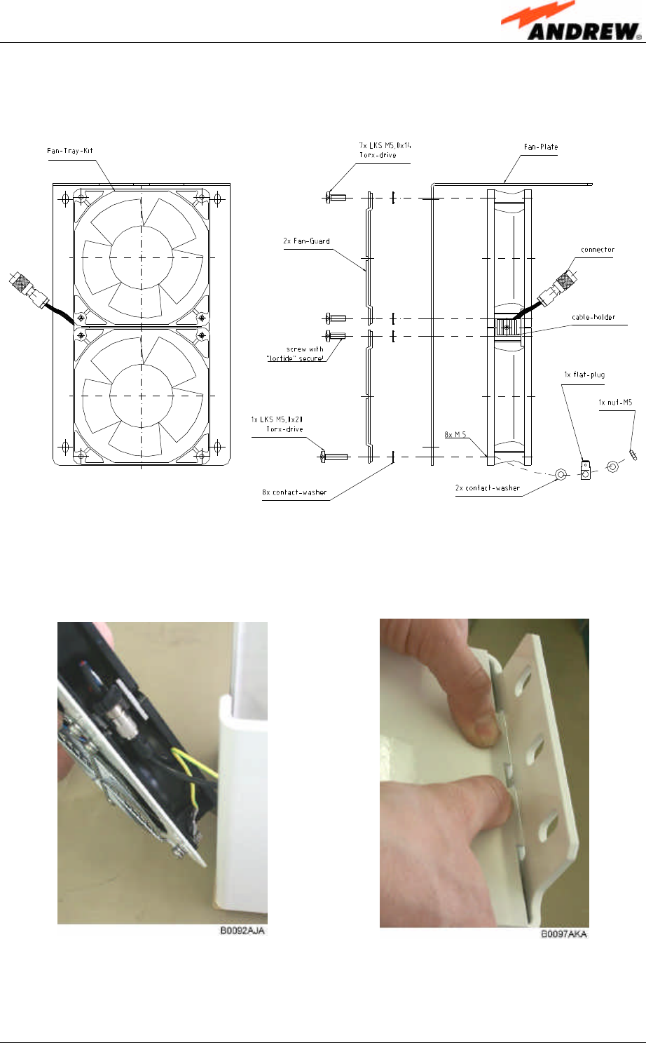
an appropriate tool for the following screwing procedures.
4. To remove the fan plate, loosen the M5 nut (as shown in figure 7-1 Fan unit
assembly) as well as the corresponding contact washers and flat-plug. Then,
loosen the eight tallow-drop screws by which the fan unit is screwed to the fan
plate (seven screws M5x14 and one M5x20).
F Note: Do not unscrew the screws completely. Only loosen them till the
fan unit can be taken off.
Fan unit connector
Earth bonding cable
7 Maintenance
ID No: 159967 Page 37
5. To mount the new fan unit, position it correctly and screw it to the fan plate with
the seven tallow-drop screws M5x14 and the one tallow-drop screw M5x20.
Fasten this screw again with the M5 nut.
G0946M2
figure 7-1 Fan unit assembly
6. Reconnect the earth bonding cable and the fan connector (see step 3). Then,
place the fan plate back into its original position and fix it tight as shown below.
7. Screw the whole fan unit to the cabinet with the four tallow-drop screws M4x8
(see step 1). In order not to exceed the specified torque of 330 Ncm use an
appropriate tool.
User’s Manual for Remote Unit
MMR8/19
Page 38 M0106A7E.doc
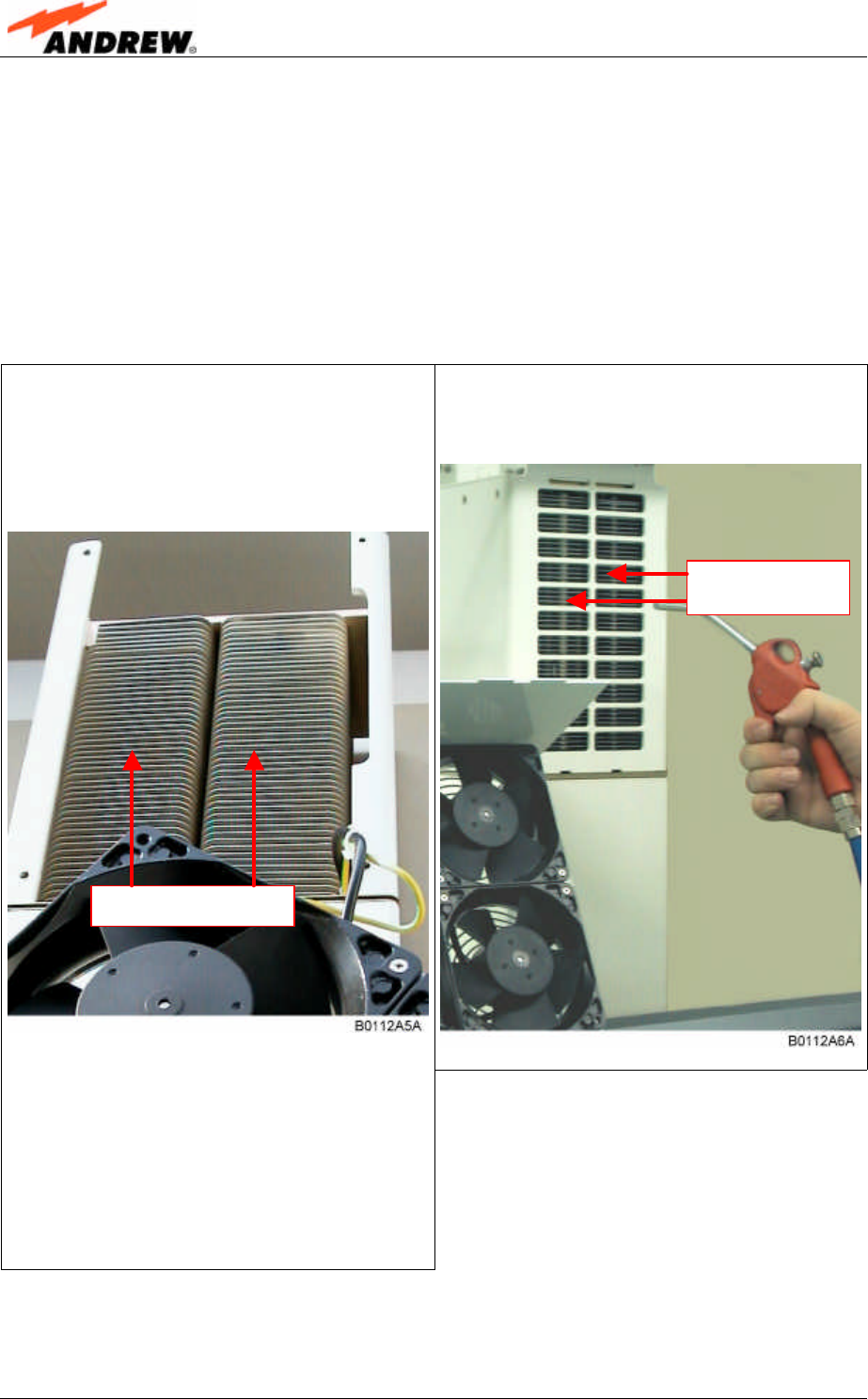
7.3. CLEANING THE HEAT SINK
F Note: Read the health and safety warnings in chapter 1.2 Health and
Safety Warnings as well as the instructions in chapter 7.1 General
before starting with the replacement procedure. Then, proceed as
follows:
1. Switch off the remote unit. Make sure that mains is disconnected for the following
procedure.
3. Use compressed air (max. 5 bar) to
blow out the heat sink from back to
front:
2. Remove the fan plate with the fan unit
from the remote unit as described in
chapter 7.2 Replacing the Fan Unit,
steps 1 and 2:
4. In case the dirt cannot be blown out
completely but part of it sticks to the
ribs of the heat sink, clean the
concerned parts carefully from the
front using e.g. a brush. Take care
that the material is not scratched or
damaged.
5. After cleaning the heat sink mount the fan unit again according to chapter 7.2
Replacing the Fan Unit, steps 6 and 7. Then, switch the remote unit back on.
Compressed air
(5 bar max.)
Brush (not metallic)
8 Appendix
ID No: 159967 Page 39
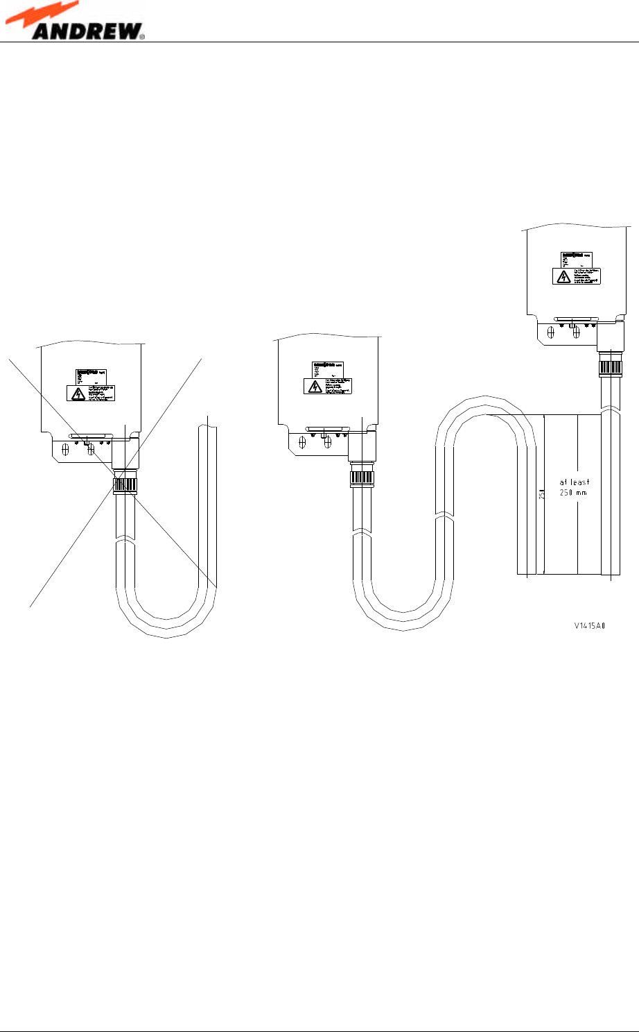
8. APPENDIX
8.1. ILLUSTRATIONS
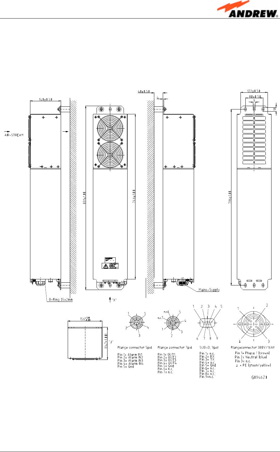
figure 8-1 Installation drawing
User’s Manual for Remote Unit
MMR8/19
Page 40 M0106A7E.doc
8.2. SPECIFICATIONS
8.2.1. Mechanical Specifications
Height (max.): 32.8” (83.2 cm)
Width (max.): 6.2” (15.7 cm)
Dimensions *
Depth (max.): 5.8” (14.8 cm)
Weight ~ 40 lbs (20 kg)
Mounting** ⇒ Do not block air in- and outlet!
⇒ Vertical mounting compulsory
* With mounting brackets, without connectors
** To ensure sufficient airflow when mounting the unit in enclosed spaces, two lid openings (one for
the air inlet and the other for the air outlet) have to be provided. The size of each opening must equal
at least 12x12 cm (144 cm2). Also, make sure there is no thermal short circuit between the air inlet and
air outlet.
All data is subject to change without notice!
8.2.2. Optical and Interface Specifications
Number of connectors per band 2 for IDEN/AMPS
4 for PCS
BTS
interfaces Input power +33 dBm typ. (up to +46 dBm with
UL performance degradation)
Connector N female
Output power see band specification
Antenna port
Return loss 15 dB typ. / 12 dB min.
Connectors E2000/APC 8°
Tx output power (optical) 0 to 7 dBm optical
Tx input power (RF) 0 dBm max. composite
Rx input power (optical) +7 dBm max.
Optical link budget 0 to 10 dB optical
Optical return loss 45 dB min.
Optical link
Fibre type Single mode 9/125 µm
All data is subject to change without notice!
8.2.3. Electrical Specifications
MMR8/19*
Mains power 115 V AC; 230 V AC or 48 V DC
AC power Power consumption 400 W
8 Appendix
ID No: 159967 Page 41
800 MHZ section
Frequency range 869 - 894 MHz (AMPS) or
851 - 869 MHz (LMR)
RF output power (per carrier) Analogue TDMA CDMA iDEN
⇒ 2 carriers +40 dBm +37 dBm +34 dBm +34 dBm
⇒ 4 carriers +36 dBm +32 dBm +31 dBm +31 dBm
⇒ 8 carriers +32 dBm +29 dBm +28 dBm +28 dBm
⇒ 16 carriers +30 dBm +26 dBm +25 dBm +25 dBm
⇒ 32 carriers (CDMA 20 carriers) +26 dBm +23 dBm +24 dBm +22 dBm
Spurious emissions < -13 dBm
DL output tolerance over frequency ±1.0 dB
D
L
DL output tolerance over temp. ±1.5 dB
Frequency range 824 - 849 MHz (AMPS) or
806 - 824 MHz (LMR)
IICP3 optimized NF optimized
Input ICP3 1.5 dBm -9 dBm
Noise figure 13.5 dB 5.5 dB typical
U
L
Gain 2 dB 16 dB
1900 MHZ section
Frequency range 1930 – 1990 MHz
RF output power (per carrier) GSM TDMA CDMA
⇒ 2 Carriers +39 dBm +36 dBm +33 dBm
⇒ 4 Carriers +35 dBm +31 dBm +30 dBm
⇒ 8 Carriers +31 dBm +28 dBm +27 dBm
⇒ 16 Carriers +28 dBm +25 dBm +24 dBm
⇒ 32 Carriers +25 dBm +22 dBm +21 dBm
Spurious emissions < -13 dBm
DL output tolerance over frequency ±1.0 dB
D
L
DL output tolerance over temp: ±1.5 dB
Frequency range 1850 - 1910 MHz
IICP3 optimized NF optimized
Input ICP3 1 dBm -11 dBm
Noise figure 14 dB 5.5 dB typical
U
L
Gain 2 dB 16 dB
* All data are valid for systems in a thermally steady state; i.e. after approx. 40 min of operation.
All data is subject to change without notice!
User’s Manual for Remote Unit
MMR8/19
Page 42 M0106A7E.doc
8.2.4. Environmental and Safety Specifications
Environmental and
safety
For detailed information, refer to the Environmental and Safety
Specifications leaflet for Mikom indoor/outdoor cell enhancers,
related to ETS 300 019 (European Telecommunication
Standard).
Operating
temperature range -33°C to +40°C (+50°C with degradation)
Accoustic noise <49dB(A) (@+30°C) sound pressure level
Ingress protection RF part
Fan with cover IP67
IP55
All data is subject to change without notice!
8.3. SPARE PARTS
The following lists contains all parts available for the remote unit. The configuration of
the delivered unit meets the requirements of the customer and can differ depending
on the state of the delivery.
Spare Parts List for Remote Unit MMR8/19
Designation: ID No:
MMR8/19 159207
Connecting Box Kit Pole Mounting 159612
Connecting Box Kit Wall Mounting 159613
Connecting Box Kit w/o Mounting Kit 158313
Fan Tray Kit 157622
Overcoat Housing Kit Pole Mounting 159624
Overcoat Housing Kit Wall Mounting 159625
Overcoat Housing w/o Mounting Kit 158384
User’s Manual for Optical Remote Unit MMR8/19 159967
Mikom reserves the right to replace the spare parts listed above by equivalent
substitutes!

9 Index
ID No: 159967 Page 43
9. INDEX
A
Abbreviations .......................................... 7
Address of Mikom ................................... 9
Alarm List.............................................. 34
Alarms
Bite and Alarms....................................... 33
Handling of Alarms.................................. 33
LED ........................................................ 33
Status Report.......................................... 33
Appendix............................................... 39
B
Block Diagram....................................... 13
C
Cleaning the Heat Sink ......................... 38
Commissioning ..................................... 31
Components
Accessories ............................................ 16
Fan Protection Kit ................................... 16
Interior .................................................... 14
Connections.......................................... 25
Antenna .................................................. 27
Optical Fibre Cable ................................. 28
Power ..................................................... 27
G
Grounding ............................................. 26
H
Health and Safety Warnings.................... 8
I
Illustrations ............................................39
Installation
Electrical................................................. 24
Mechanical ............................................. 17
International Contact Addresses............10
L
Levelling ................................................31
M
Maintenance..........................................35
Mounting
Aid Brackets............................................ 22
Fan Protection ........................................ 21
Inside Pole.............................................. 22
Pole (outside).......................................... 20
Wall ........................................................ 19
P
Preamble.................................................9
R
Remote Operation .................................31
Replacement of Fan Unit.......................36
S
Spare Parts ...........................................42
Specifications
Electrical................................................. 40
Environmental and Safety ....................... 42
Interface ................................................. 40
Mechanical ............................................. 40
Optical .................................................... 40